Systems and Technology STAVL1629 GPS Vehicle Tracking Device User Manual Part 2
Systems & Technology Corp. GPS Vehicle Tracking Device Part 2
Contents
- 1. User Manual Part 1
- 2. User Manual Part 2
User Manual Part 2
CAREU U
W
1
V
ehicle
T
racker User Guide
Chapter 3. Getting Started with CAREU U
W
1
T
o install the the CAREU U
W
1 device, follow the instructions below for basic operations.
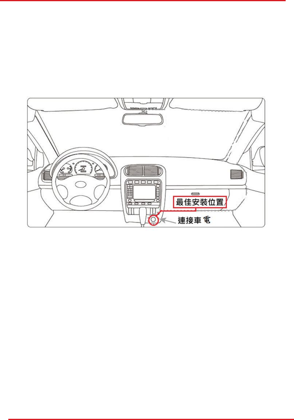
3.1
Hardware
Installation
1.
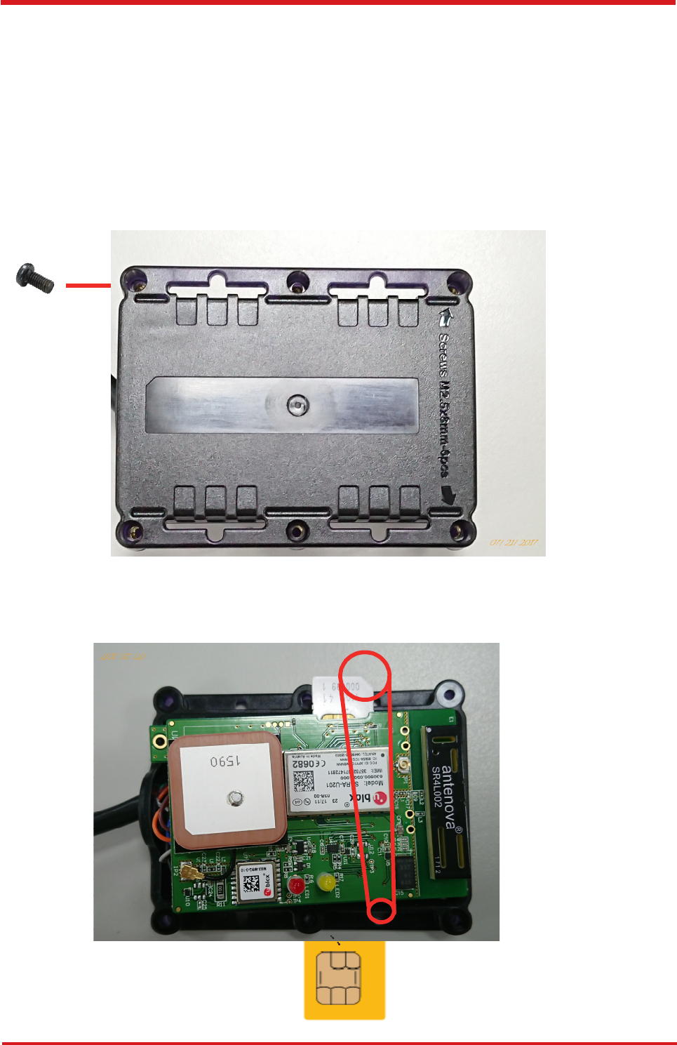
SIM Card Installation
•
Remove
the
screw
at
the
bottom
of
the
device
to
open
it.
Then
you
will
find
the
SIM
card slot inside.
•
Insert
your
SIM card
into
the
device
with
SIM card's
gold
area
down
and
the
notched
corner toward the notched edge of the SIM card socket. Make sure it is installe
d
correctly in place. Reinstall the cover.
SIM Card
Chapter 3
7

8
CAREU U
W
1
V
ehicle
T
racker User
Guide
Chapter 3
3.2
LED Indicator
1.
GPS LED Indicator
2.
GSM LED Indicator
Power Mode GSM/GPRS Status GSM LED
Power Off Off Off
Low Power Off Off
Full Power Acquiring Flash Red (three times/second)
Full Power Registered Solid Red
Power Mode GPS Status GPS LED
Power Off Off Off
Low Power Off Off
Full Power Acquiring Flash Red (five times/second)
Full Power Tracking Solid Red
CAREU U
W
1
V
ehicle
T
racker User Guide
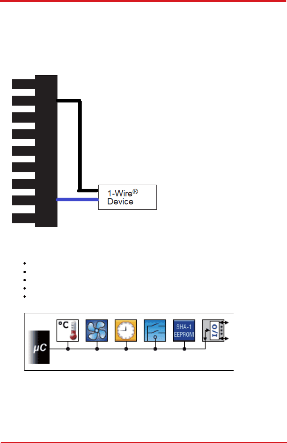
1-Wire
®
Solution
3.
3
Wit
h
bot
h
powe
r
an
d
communicatio
n
delivere
d
ove
r
th
e
seria
l
protoco
l
o
f
th
e
CARE
U
UW1, the 1-Wire® interface provides combinations of memory,mixed signal and secure
authentication functions via a single contact serial interface of the CAREU UW1 .
Benefits:
•
•
•
•
•
Single Contact Sufficient for Control and Operation
Unique ID Factory-lasered in Each Device
Power Derived from Signal Bus ("Parasitically Powered")
Multidrop Capable: Supports Multiple Devices on Single Line
Exceptional ESD Performance
9
Chapter 3

CAREU U
W
1
V
ehicle
T
racker User Guide
1-Wire
®
Accessory: iButton
®
W
ear tested
for 10 year
16 mm Diameter
5mm
Thick for F5
3mm Thick for F3
1.
DS1990A
-
F5+
The DS1990A serial number iButton
®
is a rugged data carrier that serves as an
electronic registration number for automatic identification. Data is transferred serially
through the 1-Wire® protocol, which requires only a single data lead and a ground
return. Every DS1990A is factory layered with a guaranteed unique 64-bit registration
number that allows for absolute traceability. The durable stainless-steel iButton
package is highly resistant to environmental hazards such as dirt, moisture, and
shock. Its compact coin-shaped profile is self-
aligning with mating receptacles, allowing
the DS1990A to be used easily by human operators. Accessories enable
the DS1990A
iButton to be mounted on almost any object, including containers, pallets, and bags.
Chapter 3
1
0
CAREU U
W
1
V
ehicle
T
racker User Guide
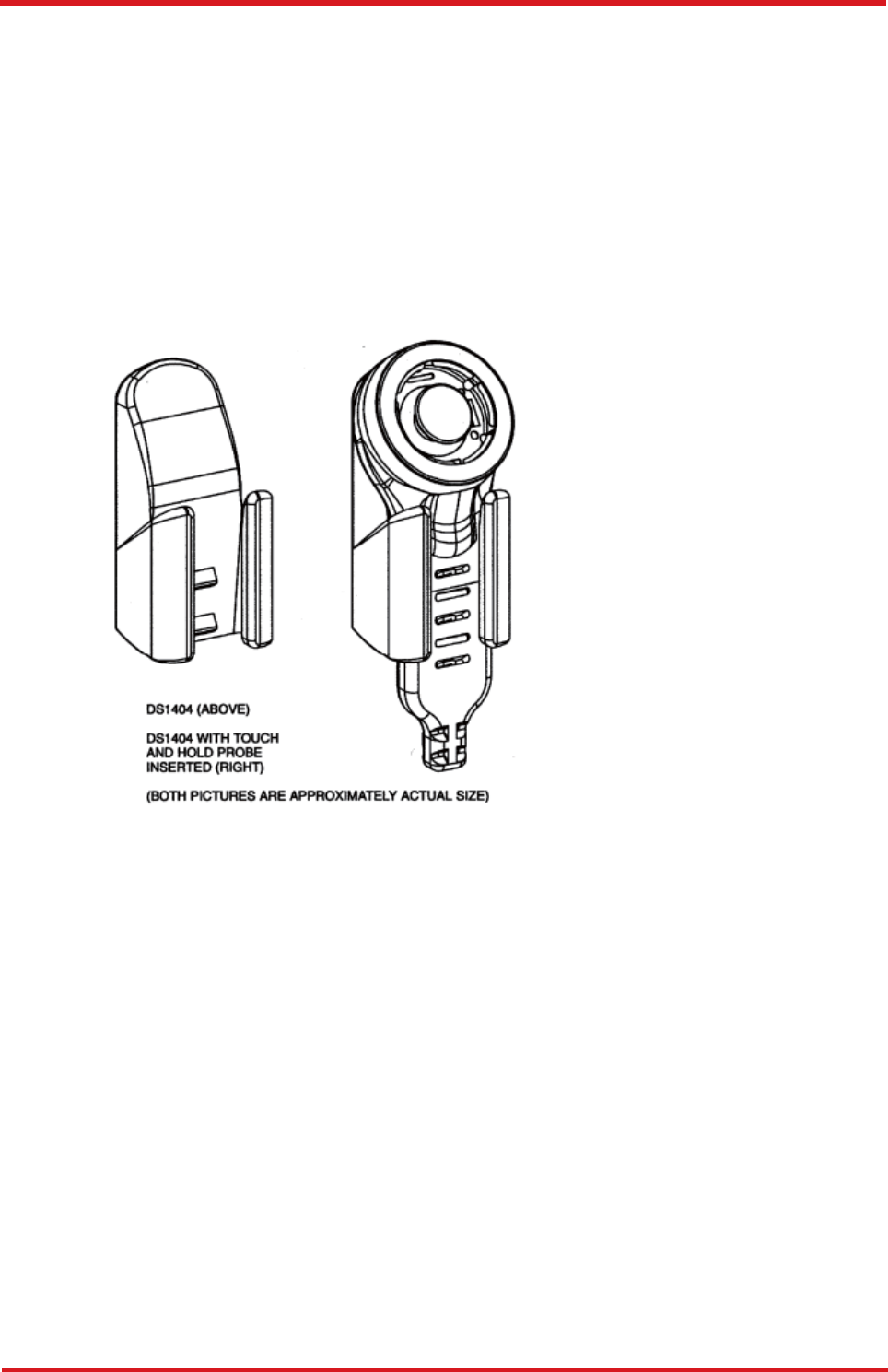
2.
T
ouch and Hold Probe & Cradle
Using four basic types of connectors, 1-Wire® RJ-11, iButton®, Touch-and-Hold
Probe, and Blue Dot™ Receptor, the DS1402 series of 1-Wire® network cables
provides connectivity for iButton®.
The cables are designed to connect any USB, serial,
or parallel port 1-Wire® adapter to any iButton®. Both, the iButton® probe cables and
the Blue Dot receptor cables can touch any iButton®, but can only hold the F5 version
iButtons. The DS1402-BR8+ is the only cable that connects to the DS1401 iButton®
Holder.
CRADLE
PROBE
11
Chapter
3
CAREU U
W
1
V
ehicle
T
racker User Guide
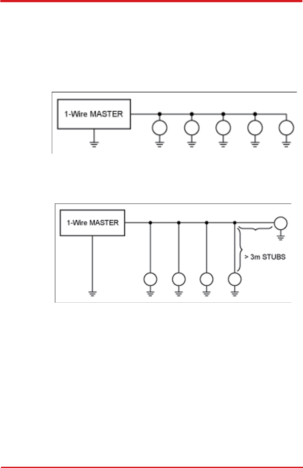
3. 1-Wire® Network Topologies
Although 1-Wire®
networks are often quite "free form" in structure, they usually fit into
a few generalized categories, based on the distribution of the 1-
Wire® slaves and the
organization of the interconnecting wires.
Linear topology. The 1-Wire
®
bus is a single pair, starting from the master and
extending to the farthest slave device. Other slaves are attached to the 1-Wire®
bus
with insignificant (<3m) branches or "stubs."
1)
Stubbed topology. The 1-Wire
®
bus is a single main line, starting at the master and
extending to the farthest slave. Other slaves are attached to the main line through
branches or stubs 3m or more in length.
2)
Chapter 3
12

CAREU U
W
1
V
ehicle
T
racker User Guide
4.
The Commands to Configure and Operate
Accessory Operation
13
Chapter 3
AT$RFIDC RFID control
Description
This command is used to set/query RFID control configuration.
Once the RFID reader senses the tag and Input 1 (Ignition) is ON,
the <Output ID> will keep ON until Input (Ignition) OFF for <Delay
Time>.
Syntax
Write Command:
AT$RFIDC=<Action>[,<Output ID>,<Delay Time>]
Parameters
<Action>
1 – Logging
When the alert condition is true, log the most re-
cent GPS position to non-
volatile flash memory
for future retrieval.
2 – Polling
When the alert condition is true, send the latest
GPS position to the remote base station.
4 – Output Control
When the RFID sense the tag, the specific out-
put port would be enabled.
<Output ID>
Output ID
1 – Output 1 2 – Output 2
3 – Output 3 4 – Reserve
5 – Reserve 6 – Reserve
7 – Reserve 8 – Reserve
<Delay Time>
Delay time in 100ms for Output control
(1~255)
Return Value
Write Command:
OK:RFIDC
Read Command:
OK:RFIDC
$RFIDC=<Action>,<Output ID>,<Delay Time>
Error Response:
ERROR:RFIDC
Example
T$RFIDC=3,1,10
OK:RFIDC
Note
RFID Report Format: Asynchronous Position
Message + <RFID Data>

CAREU U
W
1
V
ehicle
T
racker User Guide
Chapter 3
14
AT$IDRM Detect RFID
Description
Syntax
Write Command:
AT$IDRM=<Enable>,<IDCheckInterval>,< Output ID >,< Output
Duration >,<Output Toggle>
Read Command:
AT$IDRM?
Parameters
<Enable>
0 – Disable
1 – Enable
<IDCheckInterval>
(1~65535).
< Output ID >
1 – Output 1
2 – Output 2
3 – Output 3
< Output Duration >
Output duration in 100 millisecond. (0 .. 65535)
<Output Toggle>
The times from its current state to its alternate
state and back again.
(0~255)
Return Value
Write Command:
OK:IDRM
Read Command:
OK:IDRM
$IDRM=<Enable>,<IDCheckInterval>,< Output ID >,< Output Duration
>,<Output Toggle>
Error Response:
ERROR:IDRM
Example
AT$IDRM=1,10,1,5,10
OK:IDRM

CAREU U
W
1
V
ehicle
T
racker User Guide
The 1-Wire® Temperature
sensor
is for DS18B20 sensor onl
y
.
15
Chapter 3
AT$TREPORT Temperature sensor report configuration
Description
This command is used to set/query 1-Wire® temperature sensor configuration.
Syntax
Write Command:
AT$TREPORT=<Temp Sensor ID>,<Trigger Mode>,<Action>,<Min Value>,
<Max Value>,<Duration>,<Output ID>,<Output Control>
Read Comand:
AT$TREPROT?
Parameters
< Temp Sensor ID>
1 – Temperature Sensor 1
2 – Temperature Sensor 2
3 – Temperature Sensor 3
4 – Temperature Sensor 4
< Trigger Mode >
0 – Disable
1 – Inside range of <Min Value> and <Max Value>
2 – Outside range of <Min Value> and <Max Value>
< Action >
1 – Logging:
When all defined report conditions are true, log the most
recent GPS position to non-volatile flash memory for
future retrieval.
2 – Polling:
When all defined report conditions are true, send the
latest GPS position to the remote base station.
4 – Set Output:
When all defined conditions are
true, it set the state of the
assigned output port number
. When any defined condition
becomes false, the assigned output port number backs to
the original state.
< Min Value >
The minimum degrees centigrade of the effective
detecting range. Unit 0.1 degrees centigrade
(-100 ~ +850)
< Max Value >
The maximum degrees centigrade of the effective detect-
ing range. Unit 0.1 degrees centigrade
(-100 ~ +850)

CAREU U
W
1
V
ehicle
T
racker User Guide
Chapter 3
16
< Duration >
Duration in seconds which temperature sensor is
triggered inside/outside the specific range.
(1~255)
< Output ID >
The unit hardware output number. Outputs are
numbered 1 through 3. (For model U1: Output ID = 1~3)
<Output Control>
0 – Set output inactive.
1 – Set output active.
Return Value
Write Command:
OK:TREPORT
Read Command:
OK:TREPORT
$TREPORT=<Analog Input ID>,<Trigger Mode>,<Action>,<Min Value>,
<Max Value>,
<Duration>,<Output ID>,<Output Control>,<Temperature in 0.1deg.C>
Error Response:
ERROR:TREPORT
Example
AT$TREPORT=1,1,7,230,260,2,1,1
OK:TREPORT
CAREU U
W
1
V
ehicle
T
racker User Guide
1
7
Chapter 3
3.
4
Device Configuration
1.
In Windows XP
desktop, click
Start
|
All Programs
|
Accessories
|
Communications | HyperTerminal.
2.
If you are prompted to input the information of your location, complete them to proceed.
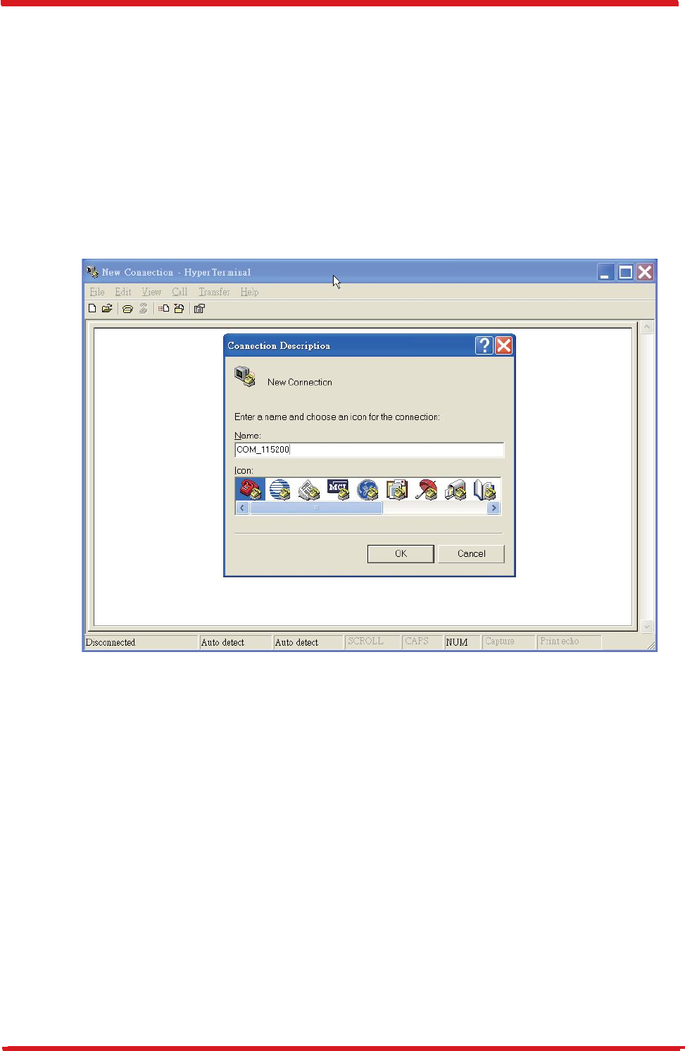
3.
On the
File
menu of
Hyper
T
erminal
, click
New Connection
.
4.
In the
Name
box,
type a name that describes
the connection. In the
Icon
box, click
an appropriate icon. Press the OK button to proceed.
5.
For Com port properties, configure as follows:
Baud Rate
--
>
Data Bits -->
Parity -->
Stop Bits -->
Flow Control -->
1
15200 bps
8
None
1
None
CAREU U
W
1
V
ehicle
T
racker User Guide
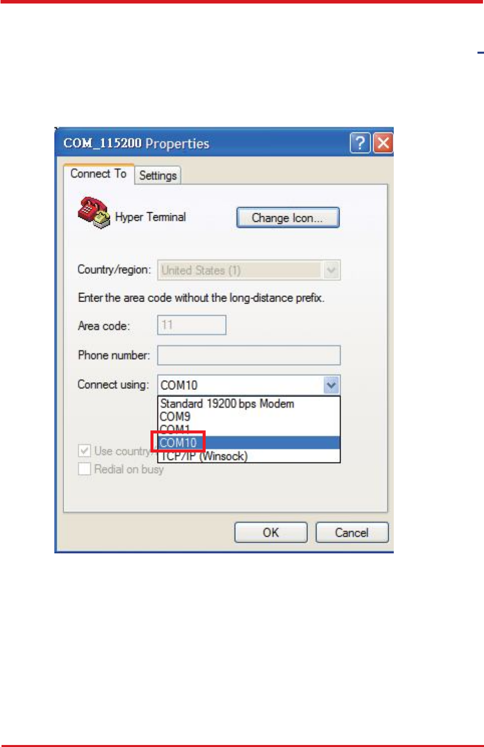
6.
In
the
connection
that
you
have
just
set
up,
click
File
|
Properties
.
Select
the
[Connect
To] tab. From the [Connect using] drop down list, select the correct com port b
y
checking it up at Windows XP's [DeviceManager] as previously mentioned on page 9
.
Go there by clicking Start | Control Panel | System | Hardware | Device Manager.
Chapter 3
18
CAREU U
W
1
V
ehicle
T
racker User Guide
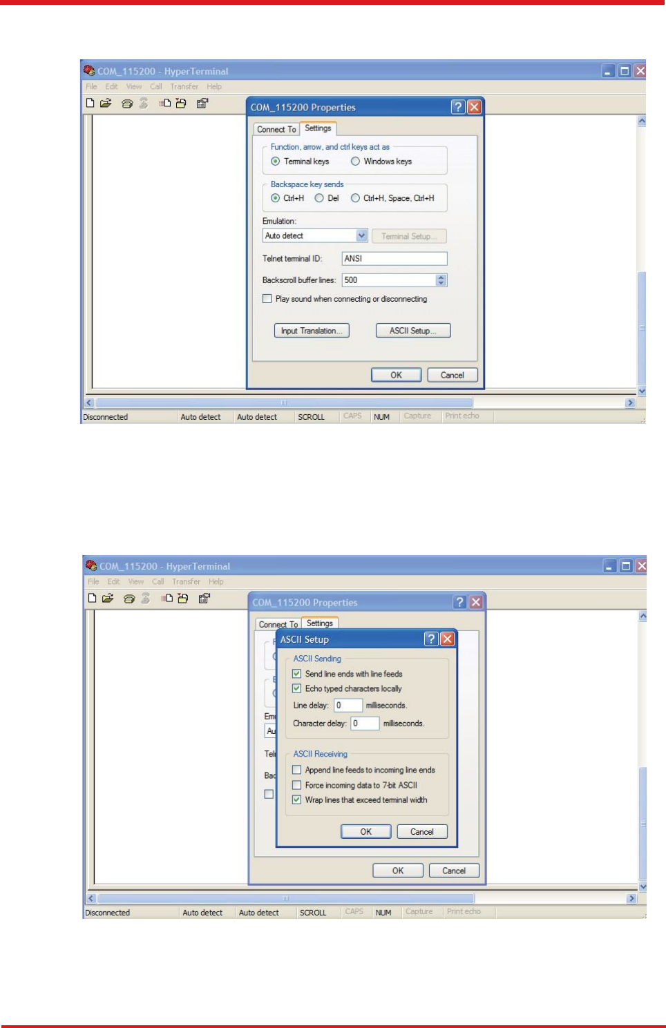
7.
In the
File
menu, click
Properties
. Click the
[Settings]
tab. Press the
ASCII Setup
button.
8.
In the [
ASCII Sending
] group box. Select both
Send line ends with line feeds
and
Echo typed characters locally. Press the OK button.
19
Chapter 3
CAREU U
W
1
V
ehicle
T
racker User Guide
9.
Connec
t
you
r
th
e
CARE
U
U
1
PLU
S
devic
e
t
o
powe
r
a
s
mentione
d
i
n
Powe
r
,
RS
-
23
2
,
an
d
I/
O
Cabl
e
C
onnectio
n
o
n
pag
e
9
.
Th
e
devi
c
e
startu
p
me
s
sag
e
wil
l
b
e
displayed.
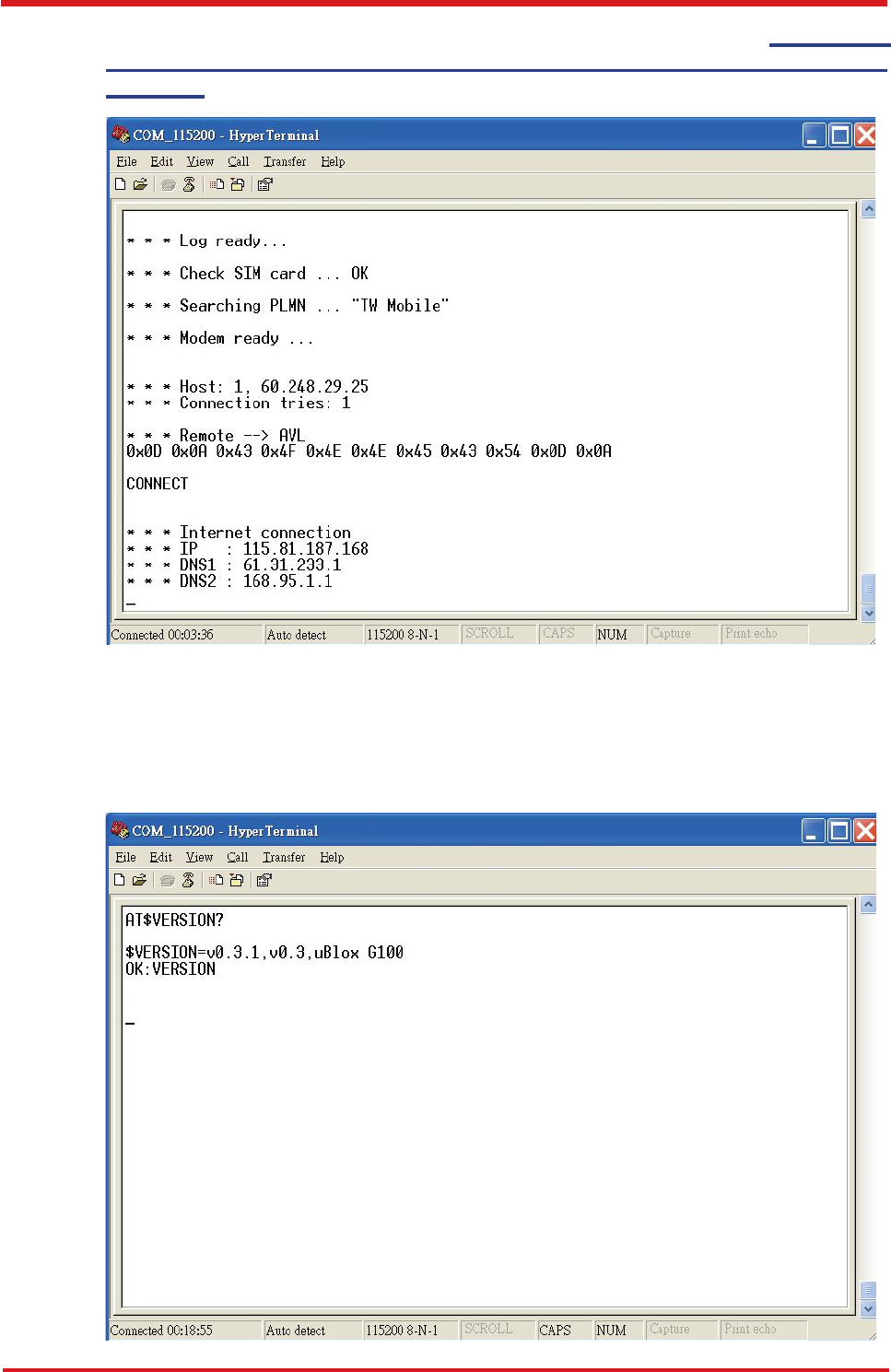
10.
I
n
[Hyper
T
erminal
]
windo
w
,
typ
e
i
n
th
e
comman
d
"
A
T$VERSION?
"
an
d
pres
s
the Enter key. The hardware and firmware version will show. As long as your
[HyperTerminal] window appears as the screenshot below, a connection between the
device and your system has already been built up and working. It is time to send all
configuration commands.
Chapter 3
20

CAREU U
W
1
V
ehicle
T
racker User Guide
3.
5
Communication Settings
Th
e
CARE
U
U
W
1
V
ehicl
e
T
racke
r
communicate
s
wit
h
you
r
contro
l
cente
r
b
y
eithe
r
SMS or GPRS (TCP/UDP). Before the device is installed into a vehicle, communicatio
n
parameters should be set.
1.
SMS Configuration
Use
A
T$SMSDST
command to set a SMS control center phone number or short code.
For example, if the SMS control center phone number is +886123456789, the
AT$SMSDST command to be issued into HyperTerminal should be:
A
T$SMSDST=+886123456789
OK
Then you can try to use cellular phone or SMS gateway to send a SMS message to
the CAREU U1 PLUS device. Send a SMS message --> "AT$MODID?"
Device will response:
$MODID=101000001
OK
This proves a successful mobile phone SMS connection.
21
Chapter 3

CAREU U
W
1
V
ehicle
T
racker User Guide
2.
GPRS Configuration
Set GPRS servers by using the folloiwng commands:
A
T$APN=internet,username,password (APN=internet, Username=username,
Password=password) OK
AT$HOSTS=1,0,60.148.19.10,6000
(Server IP
address = 60.148.19.10 and Port number =6000)
OK
AT$RETRY=5,10 (Message retry settings)
OK
AT$IPTYPE=1 (Using TCP/IP mode)
OK
AT$GPRSEN=1 (GPRS enable)
OK
AT$HB=60,1 (Heartbeat setting)
OK
Please refer to
the CAREU U
W
1 Protocol Document
for more command details.
Chapter 3
22
CAREU U
W
1
V
ehicle
T
racker User Guide
3.
6
GPS
T
racking
Configurations
After the device communication settings are done, the remote GPS tracking is ready to
function. The setting of GPS tracking can be done by using AT$PDSR command. For
example,
AT$PDSR=1,30,25,0,2,0,0,1,1(Tracking through GPRS by time interval 30 seconds)
OK
For simple testing GPRS, run the
TCP
Server U
-
Series software which is provided by
S&T. It is simple server software that can wait for device connection and data.
23
7
Chapter 3
CAREU U
W
1
V
ehicle
T
racker
User Guide
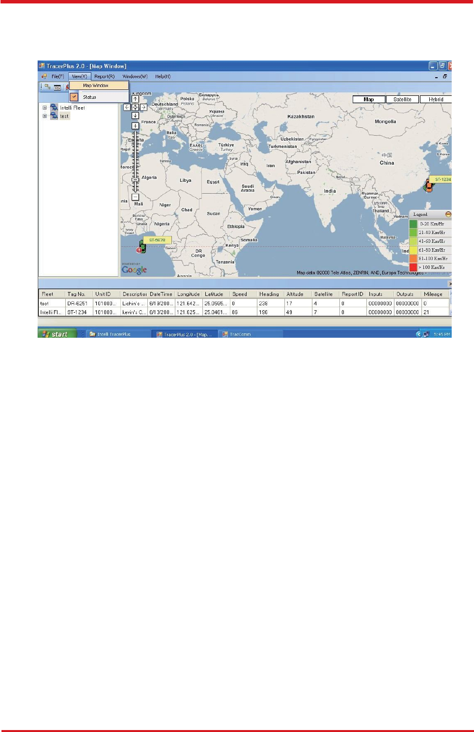
For advanced testing, you need the software Intelli
T
racerPlus. Please
request this software through your sales contact.
Y
ou can also apply for a testing account from S&T's Fleet
W
eb solution through your sales
contact.
Chapter
3
24
CAREU U
W
1
V
ehicle
T
racker User Guide
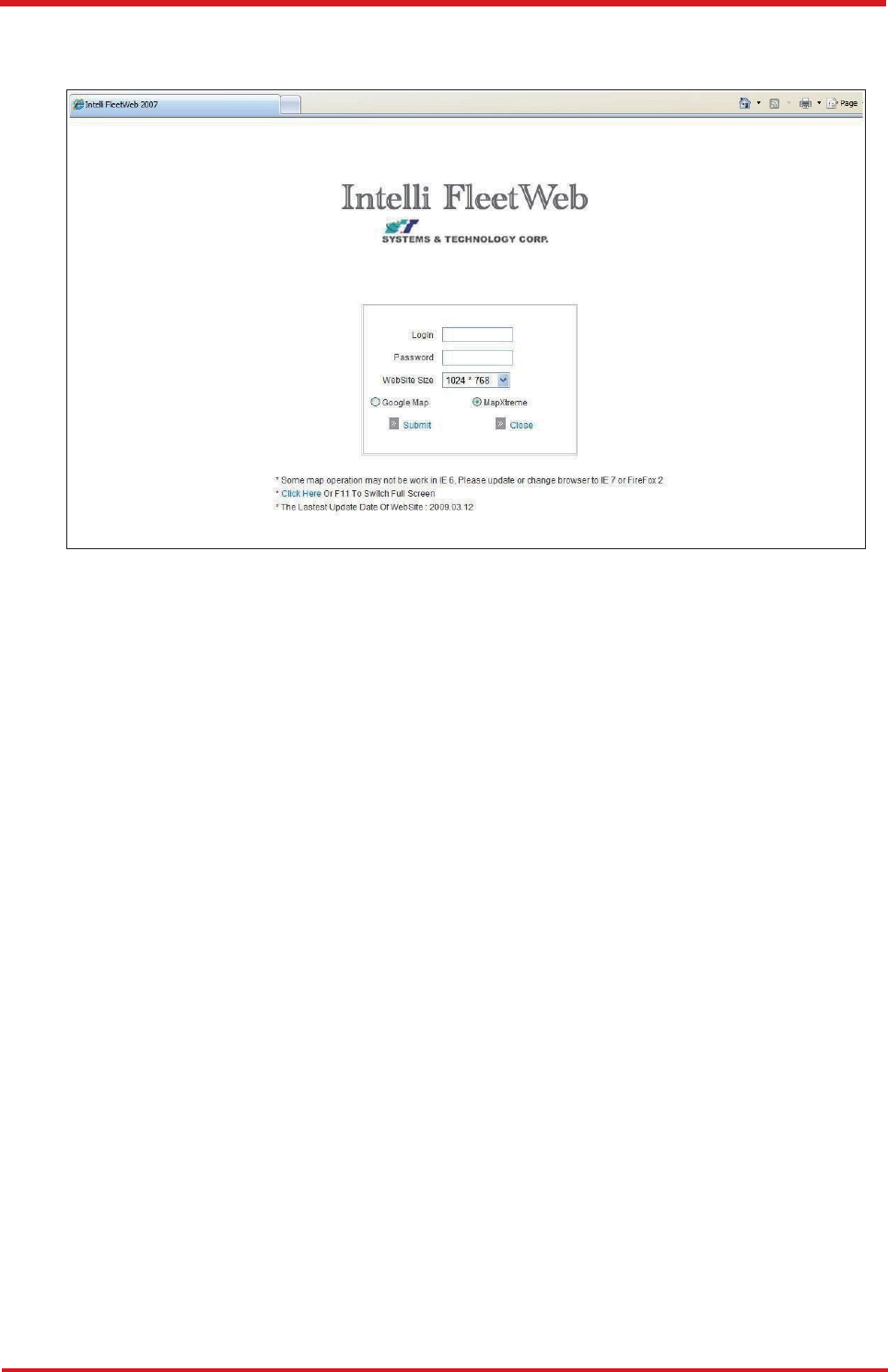
The main page of the Intelli Fleet
W
eb appears as below:
25
Chapter 3
CAREU U
W
1
V
ehicle
T
racker User Guide
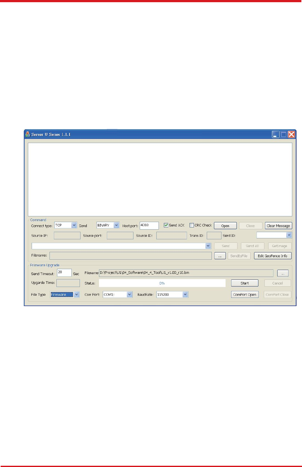
3.12
Firmware Upgrade
Th
e
firmwar
e
o
f
th
e
CARE
U
U
W
1
ca
n
onl
y
b
e
update
d
throug
h
US
B
interface
.
Wit
h
the firmware loader tool provided by S&T, firmware update can be done for the device
.
Such firmware loader runs on Windows-based systems. To upgrade the firmware, follow
the
procedure below:
1).
2).
3).
4).
Connect the device to your PC with the RS
-
232 cable.
Connect the device to power.
Power on the device.
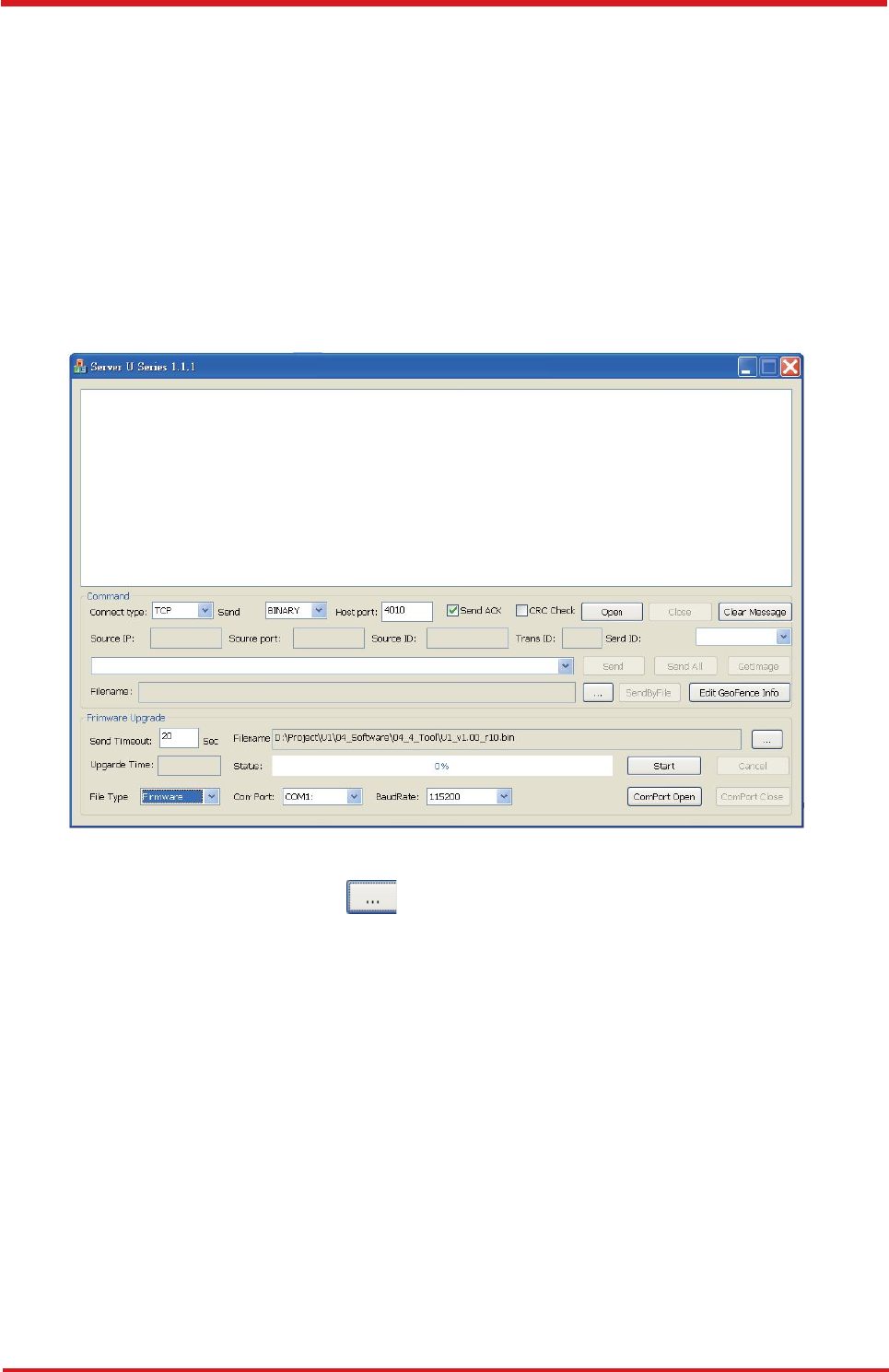
Run ServerUSeries.exe. A window displays as follows:
5).
Press browse the button
to
browse to the
firmware provided by S&
T
.
6).
7).
Press the
Start
button to run the firmware program.
After the writing progresses to 100%, it takes about 20 seconds for the update
to completes.
Firmware update completes.
8).
Chapter 3
26

CAREU U
W
1
V
ehicle
T
racker User Guide
Chapter 4.
T
echnical Specification
up to 96
Kbytes of SRAM
•
Frequency:
850/900/1800/1900/2100 MHZ
27
Chapter 4
Hardware Requirements Description
CPU ARM Cotex-M4 (84MHz )
Internal Memory
up to 512 Kbytes of Flash memory
External Memory 16M bytes
Cellullar
Cellullar Module:
• Vendor: u-blox 2G Module / 3G Module /4G Module
• Antenna: Internal 4G/3G/2G Antenna
GPS
GPS Module:
Dual Satellite System:
• GPS and GLONASS(Deafult)
• GPS and BeiDou
• GPS
• Vendor: u-blox
Sensitivity: -167 dB ( GPS & GLONASS )
-165 dB (GPS & BeiDou )
-166 dB (GPS )
@Tracking & Navigation Condition
Time to First Fix:
Cold Start: 26 Seconds at open sky ( GPS & GLONASS )
27 Seconds at open sky ( GPS & BeiDou )
29 Seconds at open sky ( GPS )
Hot Start: 1 Second
GPS Antenna
In
ternal
PITCH Antenna
LNA 28dB
GPS + GLONASS Antenna
GPS Antenna Size: 25x25x4mm
Coxail Cable Type and Length 18mm

CAREU U
W
1
V
ehicle
T
racker User Guide
Cycling life:500 Cycle
•
GPS:orange color
Note:
The specification herein is subject to change without prior
notice.
Chapter 4
28
I/O(standard)
Analog Input x
1
A. Voltage Range: 0-48 V
B. Resolution: 12 bit
Digital Input x 3
A. 1 Positive Trigger( ACC)
B. 2 Negative Trigger(Input 1,2)
Digital Output x 2
Open-Collector ,Imax 300mA x2(Output 1,2)
1-wire DS2482-100
Main power
Remove detect
Yes
GPS open/plug in detect Yes
SIM CARD SIM Card Access: External(Full-size ) support 1.8 or 1.5V
Battery
Lithium Polymer Battery
Backup Battery: 900m AH
Operating Temperature:Charge (0~40 °C),Discharge(-20~60 °C)
Battery minimum operating voltage:3.8V
(Will update at next version)
Sensor 6 axis G-sensor and Gyroscope
AGPS Yes
Power Supplies 6-48 VDC
Power Consumption
operationl mode: 40mA
( @12V working voltage, GPS position & GSM connect to server
,Without battery. )
low power mode:1.5mA
Temperature
Operating: –20 °C to +60 °C(With Battery)
Operating: –10 °C to +70 °C(Without Battery)
Storage: –20 °C to +80°C
LED Indicator • GSM:red color
Logging 150,000 positions
User Report 128 Sets
Certificate CE & FCC & E-Mark & IP67
CAREU U
W
1
V
ehicle
T
racker User Guide
System
s
&
T
echnolog
y
Corp
.
(S&T)
,
founde
d
i
n
1987
,
i
s
a
marke
t
leade
r
i
n
Automati
c
V
ehicl
e
Locating (AVL) solutions, Geographical Information Systems (GIS) and navigation.
It has formed a
professional development team to innovate the most advanced and comprehensive GPS tracking
products for the customers and has built a global service network to provide non-
stop services and
support.
Wit
h
th
e
well
-
establishe
d
marketin
g
network
s
o
f
ove
r
10
0
distributor
s
i
n
th
e
world
,
S&
T
i
s
you
r
trustworthy
tracking
solution
provide
r
.
phone or fax.
For
more
product
information,
please
contact
S&T by
Email,
29
Chapter 4
Web Site
http://www.systech.com.tw
Email
avl@systech.com.tw
Phone +886-2-2698-1599
Fax
+886-2-2698-1211

CAREU U
W
1
V
ehicle
T
racker User Guide
Chapter 5. Regulation
FCC
Regulations:
15.19(a)(3):
This device complies with part 15 of the FCC Rules. Operation is subject to the following tw
o
conditions: (1) This device may not cause harmful
interference, and (2) this device must accept any
interference received, including interference that may cause undesired operation.
15.105(b):
NOTE: This equipment has been tested and found to comply with the limits for a Class B digita
l
device, pursuant to part 15 of the FCC Rules. These limits are designed to provide reasonabl
e
protection against harmful interference in a residential installation.
This equipment generates, uses and can radiate radio frequency energy and, if not installed and
used in accordance with the instructions, may cause harmful interference to radio communications.
However, there is no guarantee that interference will not occur in a particular installation. I
f
this equipment does cause harmful interference to radio or television reception, which can b
e
determined by turning the equipment off and on, the user is encouraged to try to correct th
e
interference by one or more of the following measures:
— Reorient or relocate the receiving antenna.
— Increase the separation between the equipment and receiver.
— Connect the equipment into an outlet on a circuit different from that to which the receiver
is connected.
— Consult the dealer or an experienced radio/ TV technician for help.
Change
s
o
r
modi
f
ication
s
no
t
expressl
y
approve
d
b
y
th
e
part
y
responsibl
e
fo
r
complianc
e
coul
d
void the user‘s authority to operate the equipment.
This
device
complies
with
FCC
radiation
exposure
limits
set
forth
for
an
uncontrolled
environment.
In order to avoid the possibility of exceeding the FCC radio frequency exposure limits, huma
n
proximity to the antenna shall not be less than 20cm (8inches) during normal operation.
The
antenna(s) used for this transmitter must not be co
-
located or operating in conjunction with any
other antenna or transmitter.
RF Exposure Information
This device meets the government
’
s requirements for exposure to radio waves.
This device is designed and manufactured not to exceed the emission limits for exposure to
radio
frequency (RF) energy set by the Federal Communications Commission of the U.S. Government.
Chapter 4
30
CAREU UW1 Vehicle Tracker User Guide
Radiation Exposure Statement:
This equipment complies with FCC radiation exposure limits set forth for an
uncontrolled environment. This equipment should be installed and operated with
minimum distance 20cm between the radiator & your body.
Users and installers must be provided with comprehensive installation instructions. In
particular, it must be clear that suggested location for installation of this device at more
than 20cm away from passengers (front or rear) or bystanders.