TAIDEN 6107TP Widescreen Touch Panel User Manual
TAIDEN INDUSTRIAL CO.,LTD. Widescreen Touch Panel
TAIDEN >
User manual
Important Safety Instructions
Important Safety Instructions
1. Please read the safety precautions carefully before
installing and using the equipment.
2. Please keep this safety instructions for future
reference.
3. Please strictly adhere to the WARNINGs in the user’s
guide.
4. Please follow all the operation instructions in the
user’s guide.
5. Equipment cleaning: Make sure to turn off the power
supply and disconnect the units before cleaning.
Clean only with a dry soft cloth.
6. To prevent from any hazard use only accessories
recommended by the manufacturer.
7. To prevent from any hazard do not expose the
equipment to moisture or humidity.
8. Do not place the equipment on any uneven or
unstable stand; original product package or
appropriate package should be used to avoid damage
caused by strong impacts during transportation.
9. Adequate ventilation is good for the maintenance of
the equipment.
10. Power supply cords:
America, Japan: AC 110V~120V 60Hz
Asia, Europe: AC 220V~240V 50Hz
11. Grounding: 3-wire grounding plug.
12. To maintain the normal operation of the system,
system extension cables should be discreetly routed
to avoid being walked on or pinched by heavy items.
13. The quantity of connected units in one system should
not exceed prescribed quantity. For service, please
contact the nearest TAIDEN Service Center.
14. Do not remove the cover of the equipment at will; no
hard conductor or liquid substance should be left
inside the products.
15. For service, please contact the nearest TAIDEN
Service Center. Do not disassemble the equipment by
non-authorized personnel.
16. All TAIDEN products are guaranteed for 3 years
excluding the following cases: (please delete:
“caused by personal reasons”)
A. Damage or malfunction caused by human
negligence;
B. Damage or malfunction caused by improper
operating by operator;
C. Parts damage or loss caused by disassembling
the product by non-authorized personnel.
17. Use ONLY specified connection cable to connect the
system equipment.
18. Turn off the power supply and unplug the equipment
from the power supply in case the equipment is not in
use for a long time.
19. Upon receipt of the product, please fill out the
Warranty Card enclosed and post it to TAIDEN
Service Center nearby in your region.
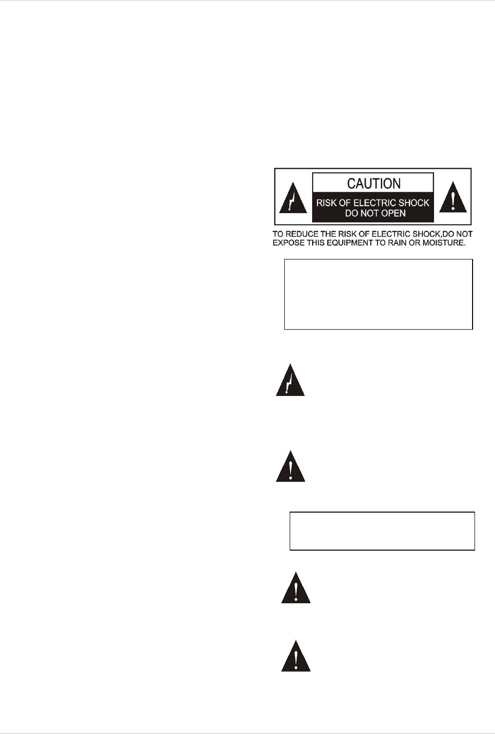
CAUTION: To reduce the risk of electric
shock, DO NOT open covers, no useable
serviceable parts inside. Refer servicing
to qualified service personnel only.
This label appears on the rear of the unit due to space limitations
The lightning flash with an arrowhead symbol, with
an equilateral triangle, is intended to alert the user
to the presence of uninsulated ‘dangerous voltage’
within the products enclosure that may be of
sufficient magnitude to constitute a risk of electric
shock to persons.
The exclamation mark within an equilateral triangle
is intended to alert the user to the presence of
important operating and maintenance (servicing)
instructions in the literature accompanying the
appliance.
WARNING: To prevent fire or shock hazard,
DO NOT expose units to rain or moisture.
Attention: Installation should be performed by
qualified service personnel only in accordance with
the National Electrical or applicable local codes.
Power Disconnect: Units with or without ON – OFF
switch have power supplied to the unit whenever
the power cord is inserted into the power source;
however, the unit is operational only when the ON
– OFF switch is in the ON position. The power cord
is the main power disconnect for all units.
I

Lithium battery safety precautions
To change battery please power off and take off the battery immediately.
Keep the battery away from heat sources to prevent fire or explosion.
Do not use a battery that is leaking, deformed, discoloured or overheats.
Take extra precautions to keep a leaking battery from fire.
Do not use a battery that emits odour or smoke.
Do not solder, disassemble, puncture or deform the battery, otherwise, it may damage the protection circuit of the battery
and cause fire, leakage or explosion.
Do not short-circuit the positive and negative electrode with wire or other metal objects, otherwise it may cause fire,
explosion, leakage or heat generation.
Do not store or transport the battery with metal objects (such as necklace or hair grip), otherwise it may cause fire,
explosion, leakage or heat generation.
Do not heat the battery or throw it into fire, otherwise it may damage the safety valve or the protection circuit of the battery
and may cause fire or explosion.
Do not put the battery in the water or moisten the electrode of the battery, otherwise it may corrode the battery and cause
fire, explosion, leakage or heat generation.
Be careful to put the battery into the charging case with correct electrode position, otherwise it may cause fire, explosion,
leakage or heat generation.
Do not leave the battery near the fire or under an environment over 60 ºC (such as in the car from direct sunlight),
otherwise it may damage the protection circuit of the battery and cause fire, explosion, leakage or heat generation.
Please charge the battery with the dedicated base plate, using other charging unit may cause fire, explosion, leakage or
heat generation.
Please use the battery in assigned unit, otherwise it may cause fire, explosion, leakage or heat generation.
Do not drop or shock the battery, otherwise it may damage the protection circuit of the battery and cause fire, explosion,
leakage or heat generation.
If battery contents get into eyes it may cause blurred vision. DO NOT rub. Rinse with clear water immediately and consult a
doctor.
If the battery leaks onto skin or clothing, wash the area immediately with clean water to avoid skin injury and fabric damage.
It will result in low battery and may damage the battery if the battery is not used for a long time. Please take off the battery,
and fully charge the battery for every three months.
Remark:
All rights reserved for translation, reprint or reproduction
Contents may change without prior announcement
All technical specifications are guideline data and no guaranteed features
We are not responsible for any damage caused by improper use of this manual
This product is conform to the rules of the European directive 2004/108/EC
If any detailed information needed, please contact your local agent or TAIDEN service center in your region. Any feedback,
advice and suggestion about the products is appreciated.
TAIDEN is the registered trademark of TAIDEN Co., Ltd.
II

Installation & User Guide
About this manual
This manual is a comprehensive guide to the installation
and operation of TAIDEN HCS-6100 series Central
Control System. It includes the detailed description of the
function and interface of the HCS-6100 system
components, system connection and installation, system
set-up and operation.
The manual is divided into the following chapters:
Chapter 1: Introduction
Introduction to the HCS-6100 system, as well as
introducing the user into structure, functions, features
and relative software.
Chapter 2: Widescreen Touch Panel
Detailed description of functions, connection,
configuration and operation of the widescreen touch
panel and the application of its accessories.
Chapter 3: Intelligent Central Control System Main
Unit
Detailed description of functions, installation, connection
and operation of the intelligent central control system
main unit.
Chapter 4: Network peripherals
Detailed description of functions and connection of the
network peripherals including wireless transceiver,
wireless router, power controller, lighting controller and
intelligent switch.
Chapter 5: Fault diagnosis
Trouble-shooting guide for simple faults.
Chapter 6: Technical Data
Mechanical and electrical details of the complete
HCS-6100 equipment.
V

Installation & User Guide
This manual is applicable to:
Widescreen Touch Panel
HCS-6107TP
7” widescreen touch panel (wireless 1-way control)
HCS-6107TPX
7” widescreen touch panel (wireless 2-way control and
wired Ethernet control)
HCS-6110TP
10.2” widescreen touch panel (wired Ethernet control)
HCS-6110TPX
10.2” widescreen touch panel (wireless 2-way control
and wired Ethernet control)
HCS-6112TP
12.1” widescreen touch panel (wired Ethernet control)
HCS-6112TPX
12.1” widescreen touch panel (wireless 2-way control
and wired Ethernet control)
HCS-6115TP
15.4” widescreen touch panel (wired Ethernet control)
HCS-6115TPX
15.4” widescreen touch panel (wireless 2-way control
and wired Ethernet control)
Intelligent Central Control System Main Unit
HCS-6000MCP2 Central control system main unit
Wireless transceiver
HCS-6100RFS Wireless transceiver (1-way, 2.4 G)
HCS-6100RFX Wireless transceiver (2-way, 2.4 G)
HCS-6100RF/ROUTER Wireless Router
IR transmission stick
CBL2PL/03 IR transmission stick
CBL3PL/03 IR transmission stick
Intelligent Controller
HCS-6000LM 4CH lighting controller
HCS-6000PM 8CH power controller
Intelligent Wall-mounted Keypad
HCS-6000SW/02 2-key wall-mounted keypad
HCS-6000SW/04 4-key wall-mounted keypad
HCS-6000SW/08 8-key wall-mounted keypad
HCS-6000SW/12 12-key wall-mounted keypad
Rechargeable Lithium-Ion Battery
HCS-6107BAT
Rechargeable Lithium-Ion battery (for 7” widescreen
touch panel)
HCS-6110BAT
Rechargeable Lithium-Ion battery (for 10”/12”/15”
widescreen touch panel)
Portable base plate (for HCS-6107TP/TPX only)
HCS-6107BKT
Portable base plate of HCS-6107TP series tunch panel
Power Adapter (for tunch panel)
HCS-ADP15V Power Adapter (for tunch panel)
8-series Distributor
HCS-0108COM 8-series distributor
VI
Chapter 1.Introduction
1.1 Summary
TAIDEN intelligent central control system achieves
y wired Ethernet
and/or
y wireless 1-way/2-way communication
via a wireless/wired color widescreen touch panel
(depending on the touch panel type), controlling all
devices in the conference venue including
y power on/off
y light adjustment
y screen up/down
y curtain open/close
y diverse multimedia devices (e.g. DVD, media matrix,
projector, etc.).
The operator can control the complicated conference
and environment devices easily through intuitive
visualized interface.
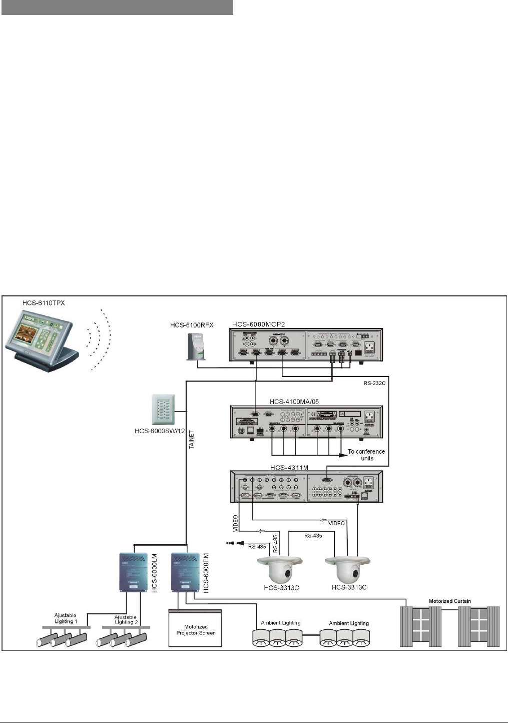
Figure 1.1 System overview
1

The system is composed of one or more of the
following:
Widescreen Touch Panel
HCS-6107TP
7” widescreen touch panel (wireless 1-way control)
HCS-6107TPX
7” widescreen touch panel (wireless 2-way control and
wired Ethernet control)
HCS-6110TP
10.2” widescreen touch panel (wired Ethernet control)
HCS-6110TPX
10.2” widescreen touch panel (wireless 2-way control
and wired Ethernet control)
HCS-6112TP
12.1” widescreen touch panel (wired Ethernet control)
HCS-6112TPX
12.1” widescreen touch panel (wireless 2-way control
and wired Ethernet control)
HCS-6115TP
15.4” widescreen touch panel (wired Ethernet control)
HCS-6115TPX
15.4” widescreen touch panel (wireless 2-way control
and wired Ethernet control)
Intelligent Central Control System Main Unit
HCS-6000MCP2 Central control system main unit
Wireless transceiver
HCS-6100RFS Wireless transceiver (1-way, 2.4 G)
HCS-6100RFX Wireless transceiver (2-way, 2.4 G)
HCS-6100RF/ROUTER Wireless Router
IR transmission stick
CBL2PL/03 IR transmission stick
CBL3PL/03 IR transmission stick
Intelligent Controller
HCS-6000LM 4CH lighting controller
HCS-6000PM 8CH power controller
Intelligent Wall-mounted Keypad
HCS-6000SW/02 2-key wall-mounted keypad
HCS-6000SW/04 4-key wall-mounted keypad
HCS-6000SW/08 8-key wall-mounted keypad
HCS-6000SW/12 12-key wall-mounted keypad
Rechargeable Lithium-Ion Battery
HCS-6107BAT
Rechargeable Lithium-Ion battery (for 7” widescreen
touch panel)
HCS-6110BAT
Rechargeable Lithium-Ion battery (for 10”/12”/15”
widescreen touch panel)
Portable base plate (for HCS-6107TP/TPX only)
HCS-6107BKT
Portable base plate of HCS-6107TP series tunch panel
Power Adapter (for tunch panel)
HCS-ADP15V Power Adapter (for tunch panel)
8-series Distributor
HCS-0108COM 8-series Distributor
2

1.2 Functions and features
1.2.1 Widescreen touch panel
16:9 widescreen high resolution color display
High brightness, high contrast ratio and wide
viewing angles
Latest graphic user interface
Supports wireless control (2.4 GHz)(depending
on the touch panel type)
Comes with wired Ethernet port, supporting
computer control and website control (depending
on the touch panel type)
Mini USB port and Type A USB port
Supports SD card (up to 4 GB)
Programmable touch buttons
AV interface, Multimedia video that supports
various formats and PIP (picture in picture)
function
Built-in speaker
Movable base, with built in Lithium-Ion battery for
more than 8 hours of continuous operation(for
HCS-6107TP/TPX only)
Portable battery pack(for HCS-6110, HCS-6112
and HCS-6115 series only)
Optional color: black and gray
1.2.2 Intelligent central control system main unit
Open programmable control platform, user-friendly
Chinese/English operation interface
Exclusive dynamic configurable RS-232C/485
ports, supporting all kinds of control protocols,
seamlessly integrated with Digital Conference
System, constitute perfect intelligent conference
solutions
Built-in IR learning, no learning apparatus needed,
easy to use
Audio mixer with volume control (2 channel stereo
inputs with independent volume control, 1 channel
stereo output)
8 IR output ports used for remote control of the
VCR, DVD, CD, MD and projectors
8 digital I/O control ports and 4 low relay control
ports for controlling currently connected devices
such as projector lift (up/down), curtains
(open/close), projector (pitching), lightings (on/off),
and so on
8 RS-232C ports (RS-232 (1) ~ (3) are 1-way ports,
RS-232 (4) ~ (8) are 2-way ports) can control video
matrix or plasma display
Front panel LCD, LED display function and real
time display
Bilingual (Chinese/English) software for system
configuration
User-defined scene save and recall facilities
Computer interface RS-232 connection to the
computer for executing configuration, supervisory
controlling and uploading program from the
computer to the central control system main unit
1 RJ-45 as Ethernet interface, connection to
computer software or wired touch panel, executing
commands via remote control
Cooperates with wireless 2-way touch panel and
wireless transceiver, executing commands via
wireless remote control
3

1.3 PC software
4
Click “HCS-6000W.exe” in your CD-ROM to install
intelligent central control system PC software on your
computer.
This series PC software is designed for TAIDEN
intelligent central control system main unit and touch
panel, used for customer programming the logic
functions of HCS-6000MCP2 intelligent central control
system main unit and the user interface of HCS-6100
series touch panel. Includes:
CS-TP vision designer
Designed for programming customer made
interface of HCS-6100 series touch panel.
CS-IR manager
Interacts with HCS-6000MCP2 intelligent central
control system main unit for IR code learning and
management. (Refer to 3.7.2)
CS-logic programmer
Programming the logic of HCS-6000MCP2
intelligent central control system main unit to
execute central control functions to various
devices. (Refer to 3.7.1)
CS-monitor manager
Monitors and manages HCS-6000MCP2 intelligent
central control system main unit. (Refer to 3.6)
Please refer to the online help file of corresponding
software for detailed operation.
Path on computer:
”Start” → ”Programe” → ”TAIDEN HCS-6000”
→ ”HCS-6000W 2.0.0.0” → ”Help”.
) Programming the logic of HCS-6000MCP2
intelligent central control system main unit
and the interface of the HCS-6100 series
touch panel should only be done by
professional engineers who have been trained
or with similar experience.
Note:

Chapter 2.Widescreen touch panel
2.1 Summary
HCS-6100TP series widescreen touch panel is the
main operation platform for user in TAIDEN central
control system. All control facilities of TAIDEN central
control system can be carried out via the function
buttons of the touch panel.
HCS-6100TP series touch panel feature:
16:9
high resolution
high contrast
high brightness
large viewing angle
true color TFT-LCD screen
AV interface
supporting various format of multimedia video and
PIP function
audio function and USB interface
supporting SD card (maximum 4 GB)
wireless (2.4 GHz) and wired Ethernet remote
controlling (depending on the touch panel type).
Types:
HCS-6107TP
7” widescreen touch panel (wireless 1-way control)
HCS-6107TPX
7” widescreen touch panel (wireless 2-way control and
wired Ethernet control)
HCS-6110TP
10.2” widescreen touch panel (wired Ethernet control)
HCS-6110TPX
10.2” widescreen touch panel (wireless 2-way control
and wired Ethernet control)
HCS-6112TP
12.1” widescreen touch panel (wired Ethernet control)
HCS-6112TPX
12.1” widescreen touch panel (wireless 2-way control
and wired Ethernet control)
HCS-6115TP
15.4” widescreen touch panel (wired Ethernet control)
HCS-6115TPX
15.4” widescreen touch panel (wireless 2-way control
and wired Ethernet control)
5
2.2 Controls and Indicators
(a) 7” Widescreen Touch Panel
(b) 10” Widescreen Touch Panel
(c) 12”/15” Widescreen Touch Panel
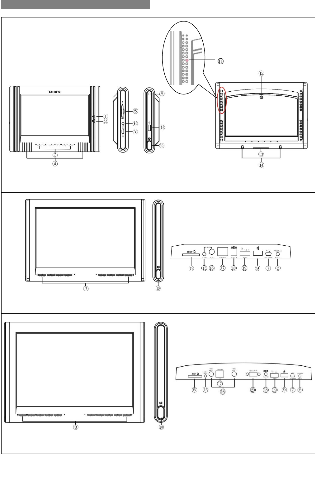
Figure 2.1 Widescreen Touch Panel
6

Figure 2.1:
1. Standby indicating light (for HCS-6107TP/TPX
only)
This indicating light will light up when the touch
panel goes to standby state.
2. Charging indicating light (for HCS-6107TP/TPX
only)
This indicating light will light up when charging and
light off after charging.
3. Touch sensitive button (programmable)
4. Built-in speaker
5. SD card slot
For SD card, supporting maximum 4G SD card.
6. RS-232C interface (reserved)
7. Mini USB interface
For uploading program and upgrading user
interface.
8. Touch pen slot (for HCS-6107TP/TPX only)
9. USB interface
For type A USB devices, such as external mouse.
10. Power/Function button
a) Touch panel in ”power-on” status: switches to
“power-off” status when pressed.
b) Touch panel in “operation status”: switches to
“set up interface” when pressed and hold for
5 seconds or switches to “exit/standby” state
when pressed for a short time.
c) “Calibration” status: exit without saving when
pressed.
11. Reset button (for HCS-6107TP/TPX only)
It is placed in the eighth hole at the second line on
the left back of the panel, and can be touched by
touch pen.
12. Rechargeable Lithium-lon battery (for
HCS-6107TP/TPX only)
13. Connective contacts to portable base plate
14. Fix slot
15. Audio input
16. Composite video input
17. Ethernet interface
Touch panel is connected to central control system
main unit via Ethernet interface (direct-connected
or via SWITCH, HUB), achieving wired control
functions.
18. Power slot
15V ~ 24V DC input for power supply
19. TAINET
Reserved
20. VGA output (for HCS-6112TP and HCS-6115TP
series only)
Warning:
) Never strike or drop the touch panel nor click
the screen by sharp objects.
) Neither use the touch panel in rain, nor
expose the touch panel to a humid
environment.
7
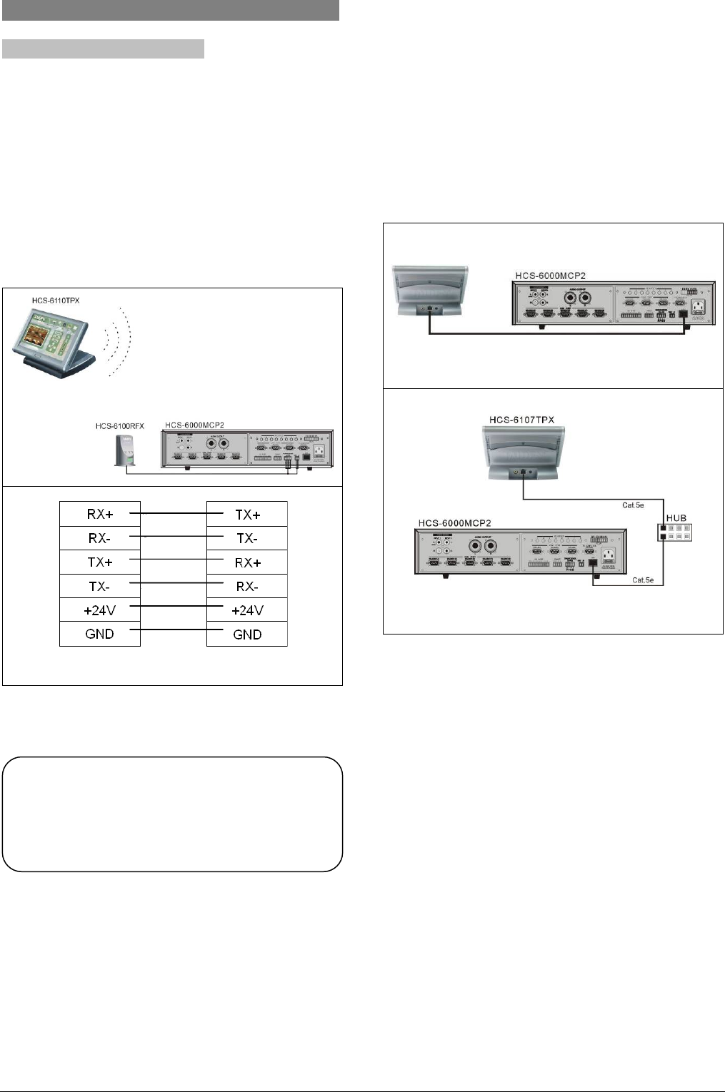
2.3 Connection
2.3.1 To HCS-6000M main unit
2.3.1.1 Wireless connection
Connect data interface and power supply slot of
wireless transceiver to the corresponding interface on
the main unit (see figure 2.2).
The 1-way wireless touch panel can send commands
to central control system main unit. The 2-way touch
panel can both send and receive commands from the
central control system main unit.
HCS-6100RFX HCS-6000MCP2
Figure 2.2 Wireless connection to HCS-6000MCP2 main
unit
2.3.1.2 Wired connection
2-way communication can be achieved easily by
connecting the Ethernet interface of the 2-way touch
panel to the Ethernet interface of the main unit via a
network cable or just connect them into the same LAN.
HCS-6107TPX
(a). Connection via network cable
(b). Connection via HUB
Figure 2.3 Wired connection to HCS-6000M main unit
Note:
) To achieve wireless 2-way communication,
wireless 2-way touch panel and wireless 2-way
transceiver should be used synchronously.
8
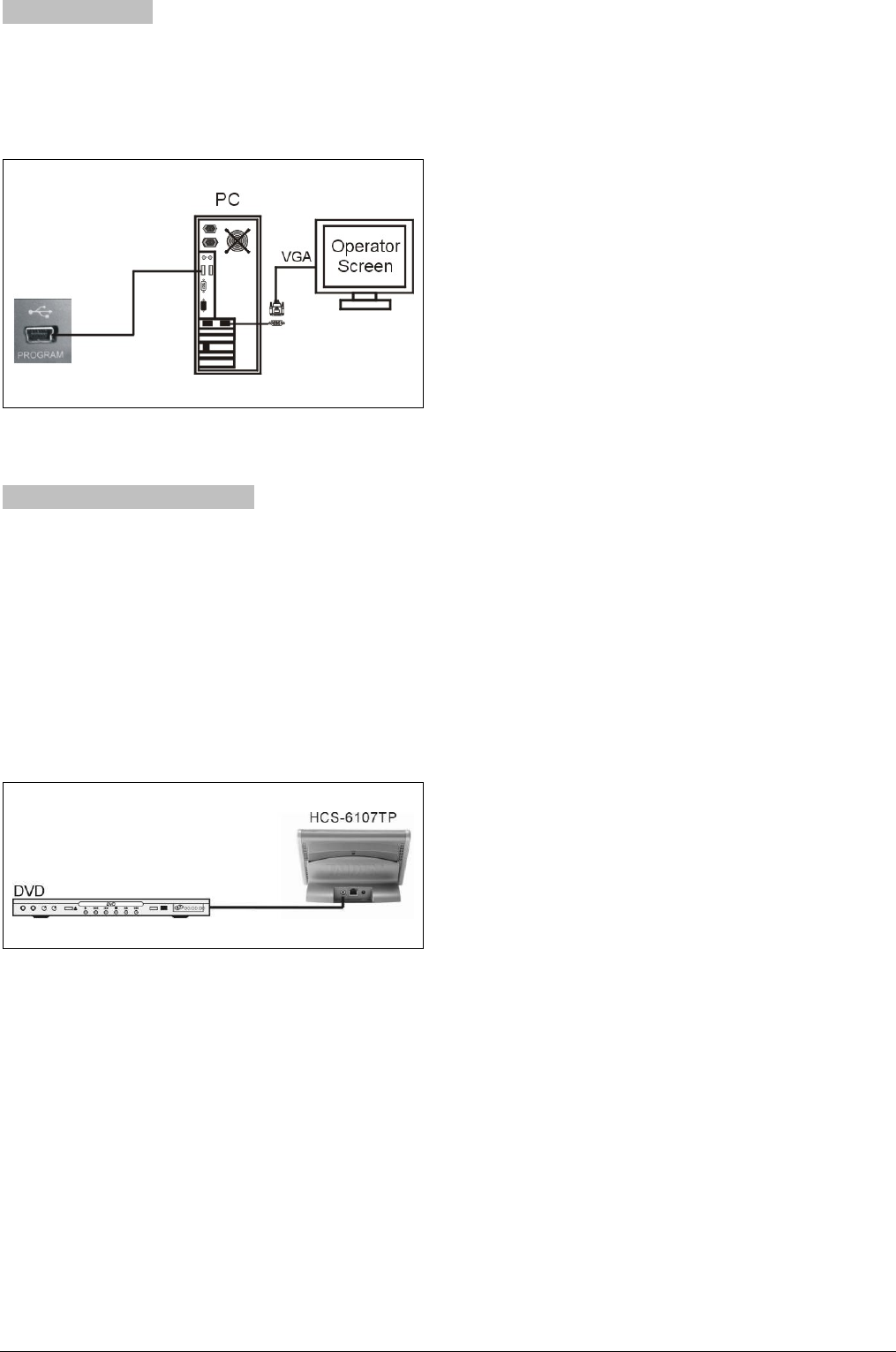
2.3.2 To computer
The touch panel can be connected to a PC by USB
interface to upload user's program, pictures, sound
files etc.
Figure 2.4 Connection to computer
2.3.3 To external video source
This series touch panel supports external video PIP
function. External video signal (such as DVD video,
camera video, etc.) can be input to the touch panel via
RCA connector and displayed in a window or
full-screen to fulfill monitor function when controlling.
HCS-6112TP/TPX and HCS-6115TP/TPX can support
2 channel videos input and display 2 channel videos
separately.
Figure 2.5 Connection to external video source
9
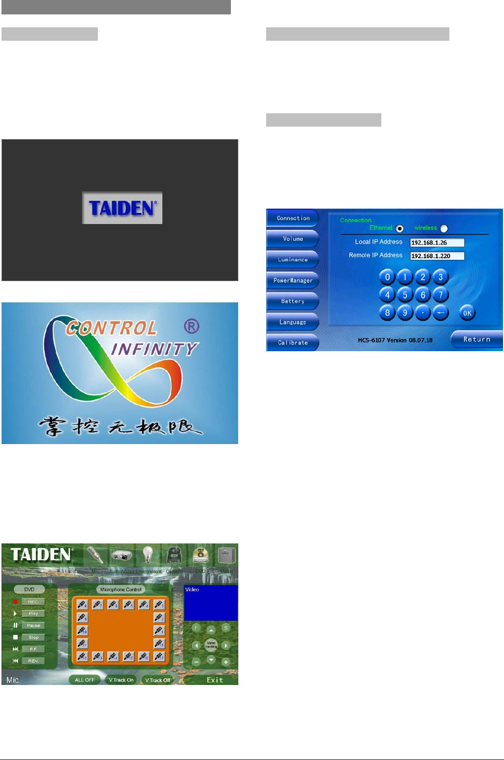
2.4 Operation
2.4.1 System startup
After installation of the battery or connection of the
power supply to the touch panel, press power button at
the right side of the touch panel to start touch panel.
The start-up logo will be displayed as shown in the
following figure:
After start up, initialization and program loading
procedures are executed, as illustrated in above figure.
Hereafter, user's previously defined and programmed
interface is displayed as shown as example in the
following figure:
Please refer to “Touch panel vision designer user’s
manual” for detailed operation instructions.
2.4.2 Download user interface program
Please refer to “HCS-61xxTP user program uploading
instructions” for detailed operation instructions.
2.4.3 Touch panel set-up
Under user defined interface, press and hold power
button for about 5 seconds will go to touch panel
configuration interface such as shown as example in
the figure below, displaying the “Connection” status:
All status of the touch panel can be setup through
touch button on the screen. The operation of all menu
items will be introduced one by one in the next
sections.
10
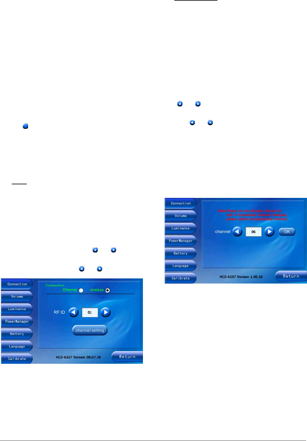
2.4.3.1 Connection
At each time “Connection” button at the left side of the
window is pressed, the above figure is displayed
Two connective modes to central control system main
unit are supported :
“Ethernet”
“wireless”
a). Wired Ethernet connection
Local IP address means: IP address of the touch panel
Remote IP address means: IP address of the main unit.
¾ use numeric keypad buttons to setup
¾ use “ ” to delete a digit
¾ use “OK” to save setting
b). Wireless connection
■ RF ID
RF ID is an ID assigned for identifying a touch panel.
RF ID should coincide with the ID used in the main unit
program. If two or more touch panels are used in one
project, every single touch panel has a different ID. The
maximum number of touch panels allowed is 8. In this
case, the RF ID numbers range from 0 to 7.
To decrease or increase ID: click “ ”, “ ” button;
to decrease or increase ID rapidly and continuously (=
auto repeat): press and hold “ ”, “ ” button.
■ Channel setting
Channel setting selects wireless frequencies. 10
frequencies are available in the system, ranging from 0
to 9.
As the touch panel is communicating with the wireless
transceiver, channel setting must coincide with the
channel of the wireless transceiver. The wireless
transceiver channel is setup by the toggle switch at the
bottom side of the transceiver.
Operation:
1. To decrease or increase channel number: click
“ ”, “ ” button; to decrease or increase ID
rapidly and continuously (= auto repeat): press and
hold “ ”, “ ” button;
2. Press “OK” to confirm current channel.
For HCS-6107TP wireless 1-way touch panel, the
interface is displayed as shown in the following figure.
The wireless transceiver and the touch panel must
be set on the same channels, in this case will
transceiver and touch panel work together.
For wireless 2-way touch panel, the interface is
displayed as shown in the following figure. If the
channel of the touch panel or the wireless
transceiver has been changed, the binding between
the transceiver and the touch panel must be
executed again (see below paragraph “Binding
process”). Only in this case will transceiver and touch
panel work together again.
11
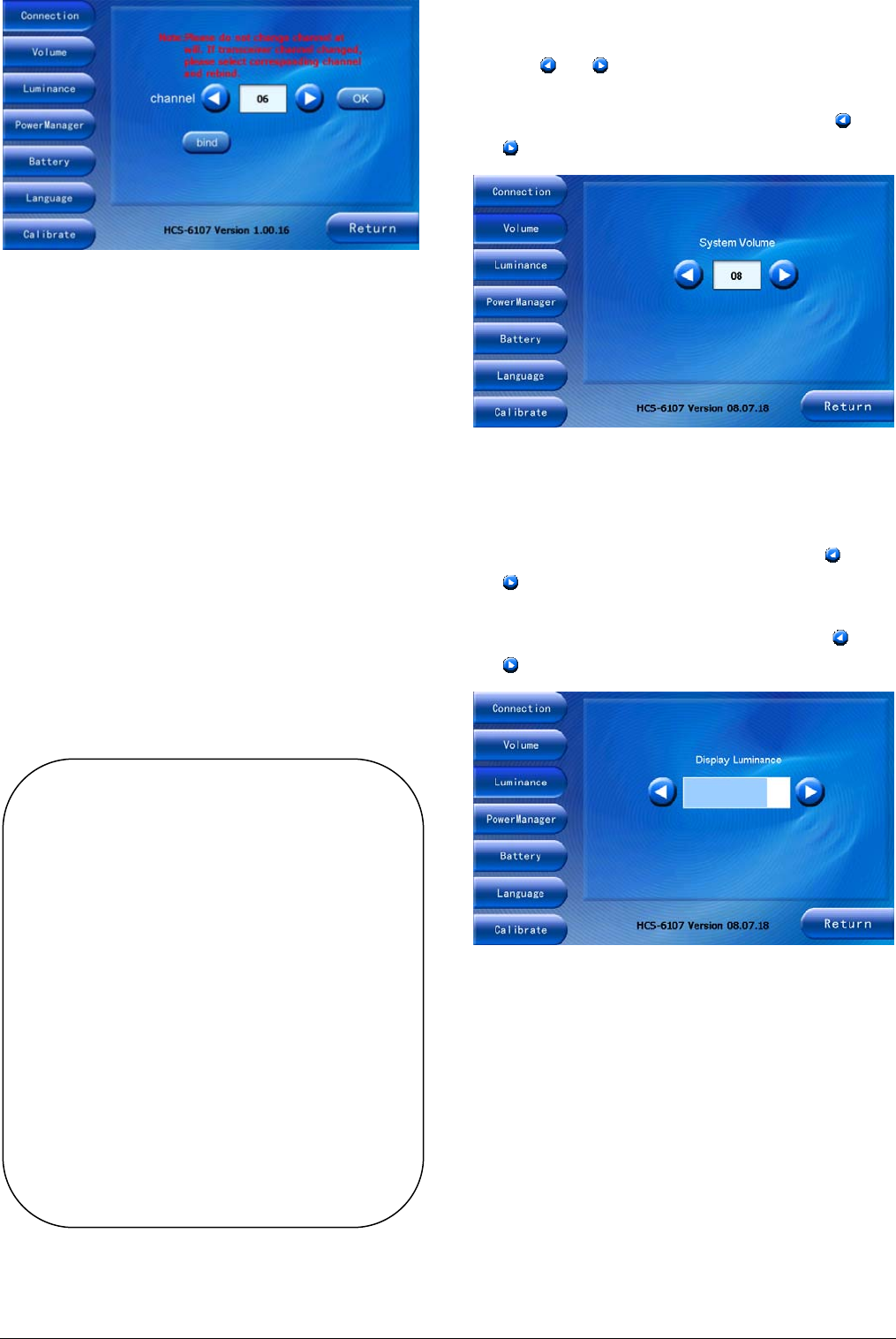
Binding process:
1. If the channel of the touch panel was changed, the
wireless transceiver must be set on the same
channel, to coincide with the channel of the touch
panel;
2. Restart the wireless transceiver;
3. Set wireless transceiver to “binding” state, by
menu operation on main unit (see section 3.5.5:
Main menu - “IP_Setup” - “WIRELESS”- “Binding”);
4. Click “bind” button on the window of the touch
panel in 10 seconds.
If the binding process has been successfully executed,
wireless communication will work unless the channel of
the touch panel or the channel of the wireless
transceiver is changed.
2.4.3.2 System Volume
¾ to decrease or increase system volume from 0~15:
click “ ”, “ ” button. 0 stands for mute.
¾ to decrease or increase system volume rapidly and
continuously (= auto repeat): press and hold “ ”,
“ ” button.
2.4.3.3 Luminance
¾ to change the luminance of the touch panel: select
“Luminance” button and adjust by pressing “ ” or
“ ” button.
¾ to decrease or increase brightness rapidly and
continuously (= auto repeat): press and hold “ ” or
“ ” button.
Note:
) The wireless touch panel and corresponding
wireless transceiver have already binding
together as factory setting. The binding will
be cancelled when changing the channel of
the touch panel or wireless transceiver. Our
recommendation: do not change the factory
setting of the channel of the touch panel or
wireless transceiver unless more than one
central control system is working separately
in the same area at the same time. It can
work at different frequency point by re-set
channel number. Or when one channel
cannot work normally due to disturbance,
you can change it to another channel.
12
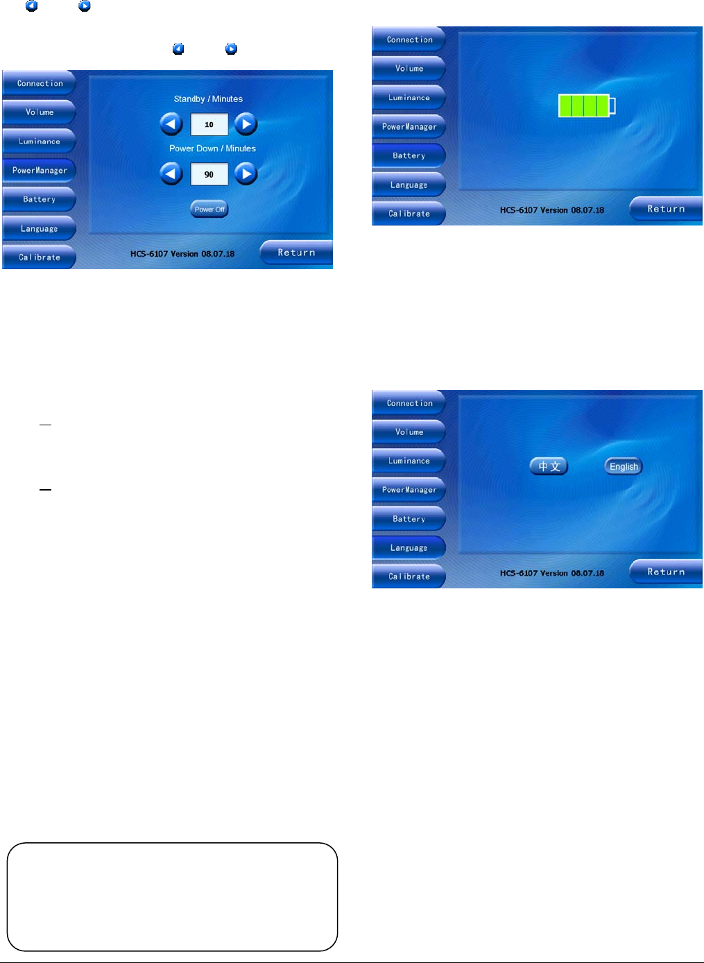
2.4.3.4 Power management
¾ to enter power management window: press “Power
Manager”.
¾ to adjust standby time and power down time: press
“ ” or “ ” button.
¾ to adjust time rapidly and continuously (= auto
repeat): press and hold “ ” or “ ” button.
Standby time:
The touch panel switches to “standby” mode once the
time selected in the Standby window elapsed. The
screen will be turned off.
¾ to return to normal working mode:
y click the touch screen
or
y press the power button at the right side of the
touch panel
or
y click the touch sensitive button under user
defined interface
Power off time:
The touch panel switches to “power off” mode
automatically once the time selected in the Power
down window elapsed.
¾ to restart the touch panel: press the power button at
the right side of the touch panel.
Time range for both standby and power off is between
1 to 90 minutes.
Standby time cannot be larger than power off time.
¾ to turn off touch panel immediately, click “Power
off” button.
2.4.3.5 Battery capacity
Click “Battery” to view the state of charge of the battery.
When battery icon shows status “empty”, please
charge the battery.
2.4.3.6 Language
Click “Language” button on the left side of the window.
The language window displays 2 buttons: “中文” and
“English”.
To select your language press the appropriate button.
Note:
) It will take 20 seconds to restart the touch panel
but take no time to return to working state from
standby state.
13
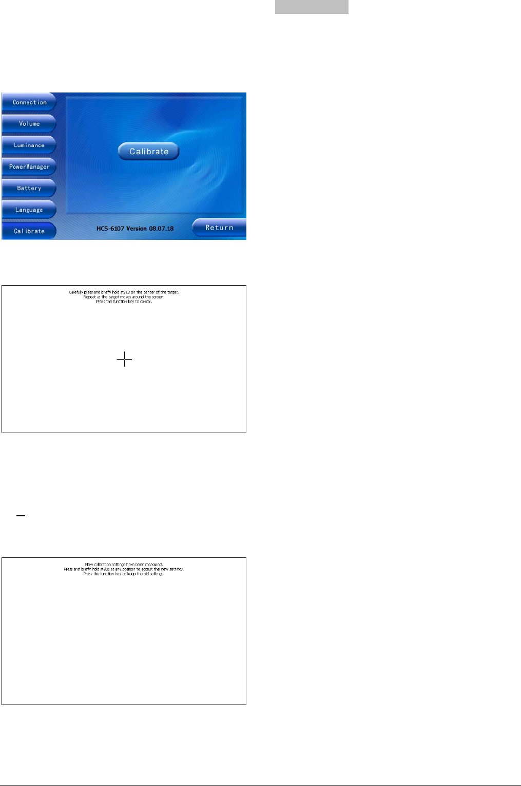
2.4.3.7 Screen calibration
If the touch buttons do not react properly when pressed,
the panel should be calibrated again.
Press “Calibration” button to enter the calibration
window of the touch panel.
Please click the crosshairs to achieve calibration,
repeat as the cursor moves around the screen.
After clicking 5 cursors, The following figure will be
displayed.
¾ click any place of the touch screen to save current
setting and return to configuration interface
or
¾ press power/function button to exit without saving
the calibration and return to configuration interface.
2.4.4 Power-off
You can power off the touch panel by setting power off
time from “Power Management” or click “Power off”
directly or by user defined power off function.
14
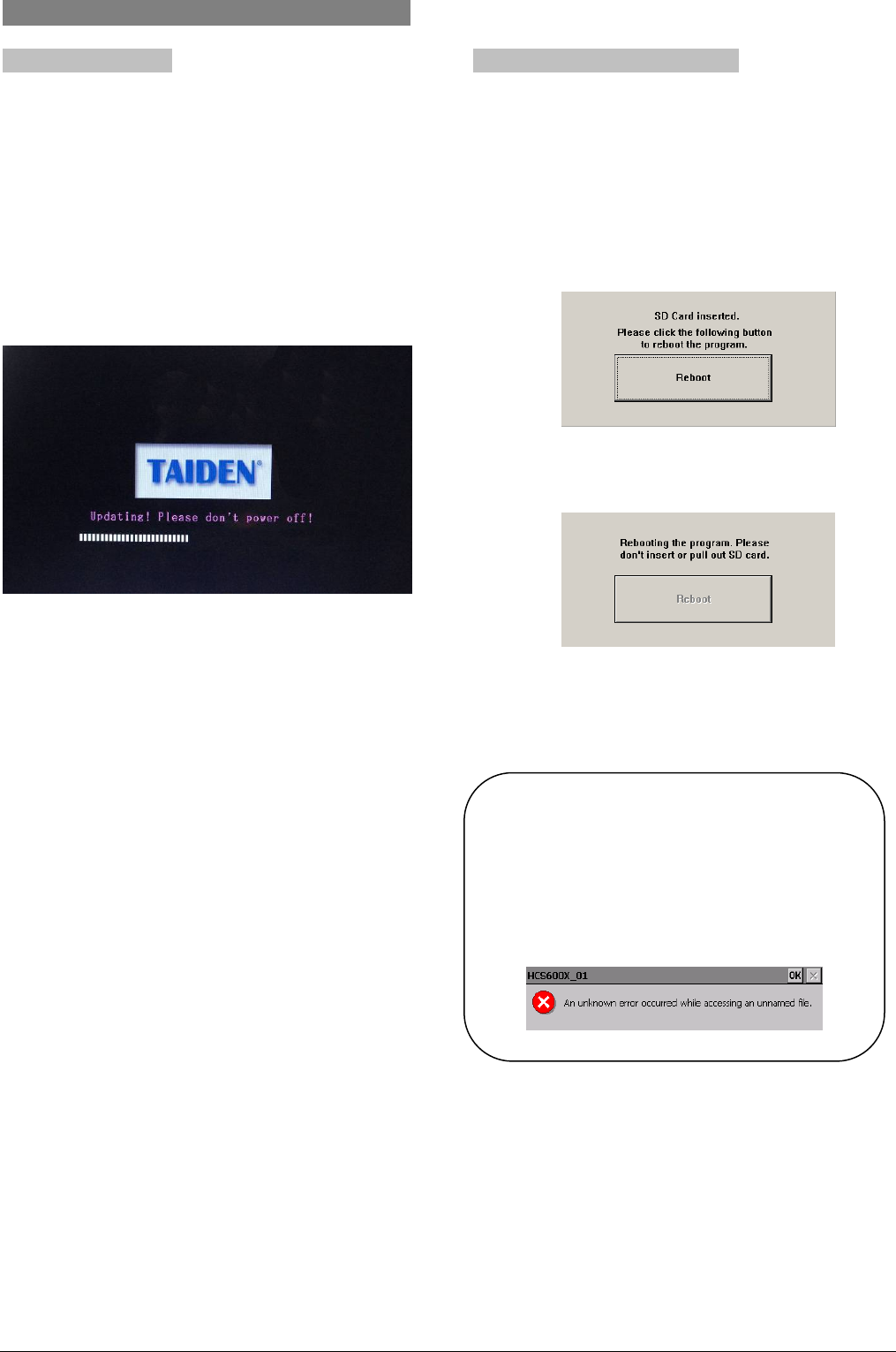
2.5 Using SD card
2.5.1 System update
Before system updating, please make sure that the
updating file name be HCS6107.bin (for 7 or 10 inches
touch panel) or HCS6112.bin (for 12 or 15 inches touch
panel) and the updating file be saved under root
directory of SD card.
Plug SD card under switch off state, and press touch
panel power on button for about 6 second to go to
update interface. “Updating! Please don’t power off!”
will be displayed on the screen as the following figure.
At this time, release power on button and wait for
updating. The process of updating will take about 1
minute, please be patient.
Do not pull out SD card or power off touch panel when
updating. After updating, touch panel will restart
automatically.
Requirements to SD card:
① Capability: 128 MB, 256 MB, 512 MB, 1 GB, 2 GB
② Format: FAT16
2.5.2 Download user project file
Plug SD card under switch off state, when power on
touch panel, it will check root directory of SD card to
find user project file “project.hex”. If the file is founded,
touch panel will load this file. If not, touch panel will
load project file from its memory.
Plug SD card under switch on state, “Reboot” will be
displayed on touch panel as the following figure:
At this time, click “Reboot” button to reboot touch panel
as the following figure. Before reboot finished, please
do not pull out SD card!
Due to memory space limitation, when the user project
file is larger than 24 MB, please save user project file
(project.hex) into root directory of SD card and load it
as above description.
Note:
) SD card can be pulled out only when the
screen page is fully loaded. Please do not pull
out SD card when reading, or it may cause
system halt as the following figure. If it
happens, please reboot the touch panel.
15
2.6 Accessory
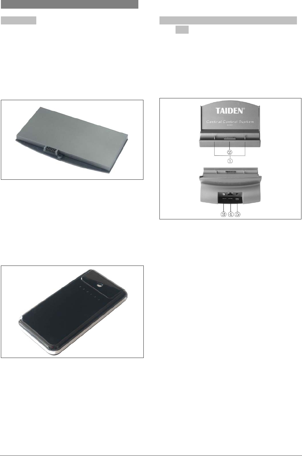
2.6.1 Battery
HCS-6107BAT Lithium-lon battery is used to give
power supply to HCS-6107TP/TPX touch panel. This
kind of battery provides high capacity rechargeable
lithium cell with 11.1 V and 2400 mAh capacity.
Charging time is 2.5~3 hours. It can work continuously
for 6 hours when the touch panel is turned on.
Figure 2.6 HCS-6107BAT rechargeable Lithium-lon
battery
HCS-6110BAT Lithium-lon battery is used to give
power supply to HCS-6110, HCS-6112 and HCS-6115
series touch panel. This kind of battery provides high
capacity rechargeable lithium cell with 16 V/19 V and
48.8 Wh capacity. Charging time is 3.5~4 hours.
Figure 2.7 HCS-6110BAT rechargeable Lithium-lon
battery
2.6.2 Portable base plate (for HCS-6107TP/TPX
only)
Portable base plate HCS-6107BKT is a dedicated base
plate for HCS-6107TP/TPX touch panel, used for
charging HCS-6107BAT or feeding power to
HCS-6107TP/TPX and providing wired connection to
main unit and video input interface.
Figure 2.8 HCS-6107BKT base plate
Figure 2.6:
1. Buckles
Match with slots of the touch panel to fix
onto the base plate.
2. Connective contacts to HCS-6107TP/TPX touch
panel
3. Composite video input interface
PIP function can be fulfilled if external video
signal is input via the RCA connector.
4. Ethernet interface
5. Power supply slot
15 ~ 24 V DC input to the touch panel or the
battery.
16
2.6.3 Power Adapter
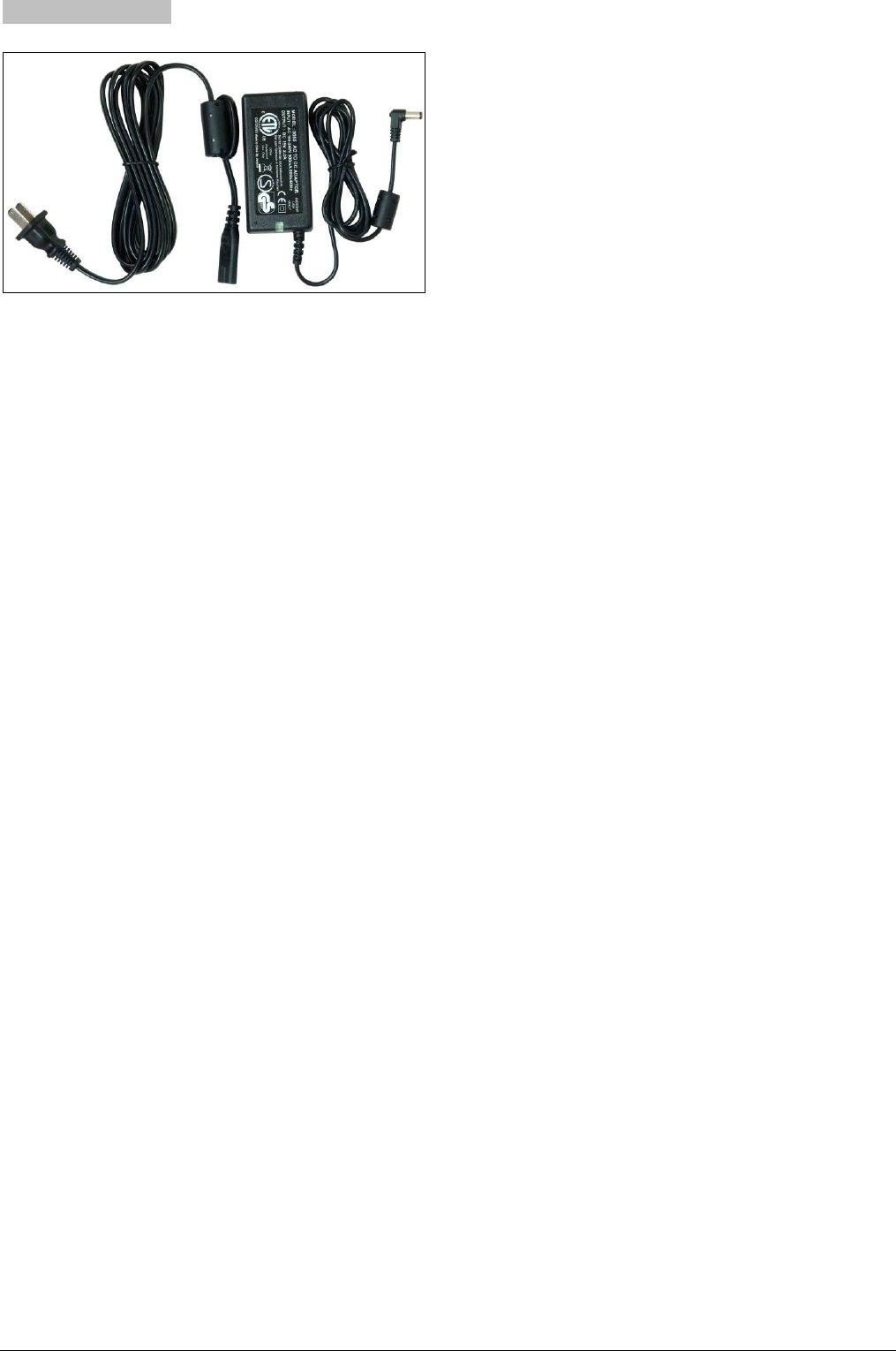
Figure 2.9 HCS-ADP15V power adapter
Insert Ø 5.5 mm plug of HCS-ADP15V adapter into
power socket on touch panel to supply power or
charge HCS-6107BAT.
Insert Ø 5.5 mm plug of HCS-ADP15V adapter into
power socket on HCS-6110BAT to charge
HCS-6110BAT.
17

Chapter 3.Intelligent central control system main unit
3.1 Summary
HCS-6000MCP2 series main unit is the heart of
HCS-6100 intelligent central control system. It integrates
audio mixer in a 2U frame and provides diverse openly
programmable remote control facilities, with strong
control logic and friendly operation interface. Exclusive
dynamic configurable RS-232C/485 control ports support
all kinds of protocols. Users can access all control
functions by computer. Used with a wireless touch panel,
the system becomes a comprehensive wireless control
system.
The connection protocol of TAIDEN's digital conference
system and the intelligent central control system
seamlessly match together to form the perfect
intelligent conference system solution.
HCS-6000MCP2 main unit can be widely used in a vast
range, such as conference hall, classroom, video
conference, remote teaching, intelligent home system
etc.
Type:
HCS-6000MCP2 Central Control System Main Unit
3.2 Controls and indicators
Figure 3.1 HCS-6000MCP2 main unit front view
Figure 3.1:
1. Mains button and indicator (red)
2. “MENU” button
a) If in current state, press “MENU” go to main
menu;
b) If in menu state, press “MENU” go to sub menu;
c) Select/Deselect in network configuration.
3. “Õ” (Left) button
4. “Ö” (Right) button
5. “Exit” button
6. “SCENE RECALL” button
If scenes have been stored, press the “SCENE
RECALL” keys (A ~ D) on the front panel to recall
the stored scene (No. 1 ~ 4 corresponds to the
scenes A ~ D respectively).
7. LED indicators of front panel
“PROGRAM” indicator:
Indicator lights up if a program/file is uploaded
from the PC via the RS-232C interface.
“LAN” indicator:
Indicator flashes if date are received or
transmitted at LAN port.
“TAINET” indicator:
Indicator flashes if data are received or
transmitted at TAINET port.
Examples:
* HCS-6100RFX wireless transceiver
transmitting the control signals from touch panel.
* TAINET network devices such as power
controller, lighting controller etc. transmitting
control signals.
“IR LEARNING” indicator:
When IR learning starts, the “IR LEARNING”
18
indicator lights up (for details refer to
“Configuration and operation - IR learning”).
“EXECUTE” indicator:
Indicator flashes if HCS-6000MCP2 transmits or
executes instructions.
“LOCK” indicator:
HCS-6000MCP2 main unit can lock the front
panel buttons to avoid illegal operation.
Locking/unlocking can be carried out by touch
panel, wall-mounted switch and by the control
software in PC. When touch panel or
wall-mounted switches are operated to control
the main unit, the front panel of the main unit is
locked and the “LOCK” indicator lights up and no
operation can be done on the front panel.
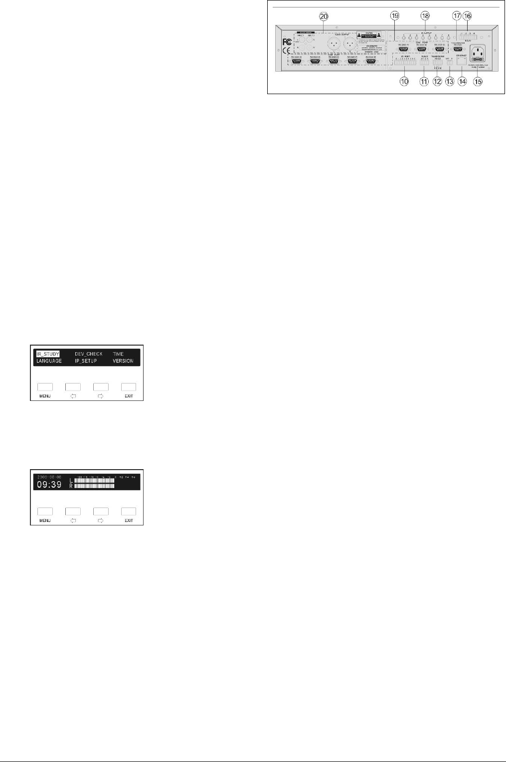
8. Display– 256×32 LCD:
Displays the status of the main unit and the menu
of system configuration.
a) Menu state
Press “MENU” to enter the setup menu in current
state and the main menu is shown as following
(for details refer to “Configuration and operation”)
b) Current state
This is the initialized state of the LCD after system
startup, displaying dynamic digital clock and the
output volume level.
9. IR receiving window:
Receives the IR signals from remote control during
IR learning; make sure the remote control aims at
the window (for details refer to “Configuration and
operation - IR learning”).
Figure 3.2 HCS-6000MCP2 main unit rear view
Figure 3.2:
10. I/O PORT:
8 programmable digital I/O ports (Logic “0”: 0 V;
logic “1”: +5 V) for the control of environment
devices such as curtains, projection screen etc.
and various environment monitoring devices.
11. TAINET bus interface:
1 TAIDEN bus interface to connect with TAIDEN
power controller and lighting controller etc. (max.
capacity of 128 devices)
Refer to the related device instructions before use;
set the proper network ID code for each device.
12. Wireless transceiver interface:
For connecting wireless transceiver and for
interaction with wireless touch panel to achieve
wireless control.
13. Wireless transceiver power supply interface:
Power supply for wireless transceiver.
14. Ethernet port:
Connecting to PC software or wired touch panel,
for remote controlling.
15. Power supply
16. RELAY 1~4 port:
4 low relay ports. Each low relay port supports 0.3
A / 125 V -AC, 1 A / 30 V -DC. Used to control
environment devices such as projection screen,
curtain, projector, and lighting etc. When the load
is motor, light or solenoid etc, strictly observe the
nominal load values allowed.
17. RS-232C (TO COMPUTER) port:
To connect the HCS-6000MCP2 main unit to the
RS-232C of a PC, using the compulsory software
of TAIDEN intelligent central control system.
The communication protocol is as following:
Interface: DB9 socket
Electric specification: Compliant to RS-232C
standard
Cable: Dedicated multicore shielded cable
for data transmission
19
Cable length: Less than 10 m
Baud rate: 19200 bps
Bit length: 8 bits
Stop bit:: 1 bit
Parity check: None
18. IR OUTPUT 1~8 port:
8 independent programmable IR control ports,
outputting 8 way IR control signals respectively
(the carrier wave is 38 KHz) to control multiple
same or different devices, such as DVD, VCR, CD,
MD and CD-R etc.
The IR port is a 3.5 mm jack; it should interact with
IR transmission stick to perform IR control: plug the
stick’s one end into the port, and put the other end
near the IR receiving window of the controlled
device. Make sure that the distance to the receiving
window is less than 20 cm.
19.RS-232C(COM PORT)port:
8 RS-232C ports:
RS-232 (1) ~ (3) are 1-way ports;
RS-232 (4) ~ (8) are 2-way ports.
For remote control of various peripheral devices
connected to the RS-232C port, such as the
projector or plasma display with RS-232C terminal.
HCS-6000MCP2 especially has improved control
functions for the RS-232C port. The setting of
serial port is dynamic and supports various control
protocols.
20. Audio mixer with volume control
2 channel stereo inputs with independent volume
control
1 channel stereo symmetrical audio output via XLR
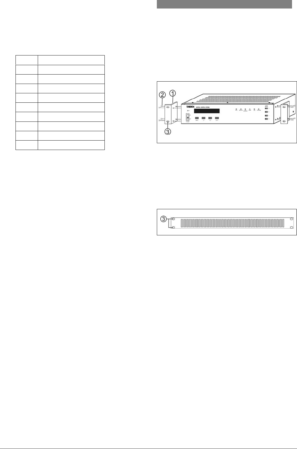
3.3 Installation
HCS-6000MCP2 main unit can be fixed in a standard
19-inch cabinet. The main unit is equipped with a pair
of fixing brackets ①. First unscrew the lateral screws
② from the housing. Then fasten the brackets with
these screws and put the main unit in the cabinet.
Finally fix the four holes ③ up with screws.
Figure 3.3 Installation of main unit
In addition, 1U metal stripes are included as decoration
to be installed between the main units in the cabinet. It
is also good for the ventilation and cooling off. Fix up
the four holes ③ with screws.
Figure 3.4 Decoration of cabinet
Pin Signal
1 Empty
2 RXD(Receive data)
3 TXD(Send data)
4 Empty
5 GND(logic ground)
6 Empty
7 Empty
8 Empty
9 Empty
20
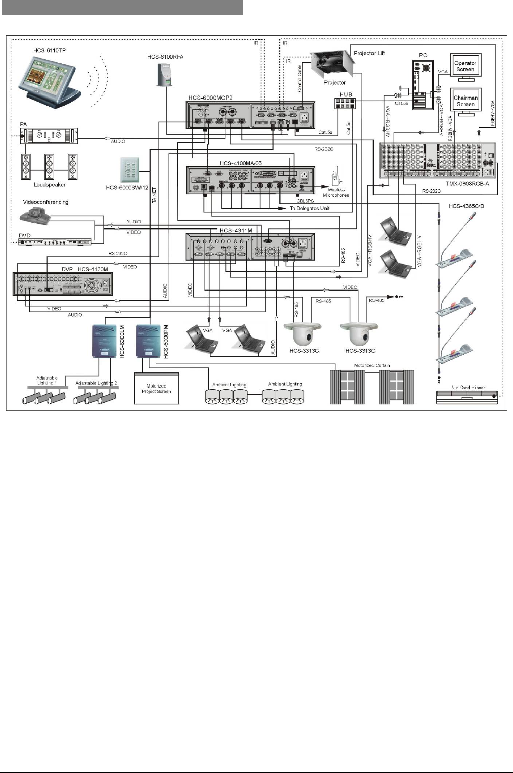
3.4 Connection example
Figure 3.5 HCS-6000MCP2 system connection
HCS-6000MCP2 is a classical main unit for intelligent central control system. The following functions can be realized with
the system configuration above mentioned:
1. Conference main unit (HCS-4100MA/05) has voting, discussion and auto-tracking facilities
2. Built-in volume control in the central control system main unit, volume can be controlled by wireless touch panel
remotely
3. Projector, DVD, PA and air-conditioner can be controlled via IR jacks
4. Opening and closing of the hatchway is controlled by low relay ports (terminal block)
5. Environment lights, curtains can be controlled by power controller via TAINET ports (terminal block)
6. The brightness of venue lighting can be controlled by lighting controller via TAINET ports (terminal block)
7. Various functions (e.g. light control, pre-stored scenes, etc.) of the wall-mounted keypads can be reached via TAINET
ports (terminal block) based on the user's pre-definition
8. Speed dome camera can be controlled by wireless touch panel
9. Turn on/off conference units by wireless touch panel
10. DVR control by RS-232
11. RGB matrix switcher control by RS-232
21
3.5 Configuration and operation
All status of the main unit can be setup via an
interactive menu on LCD and 4 operation buttons. The
operation of all menu items will be introduced one by
one in the next sections.
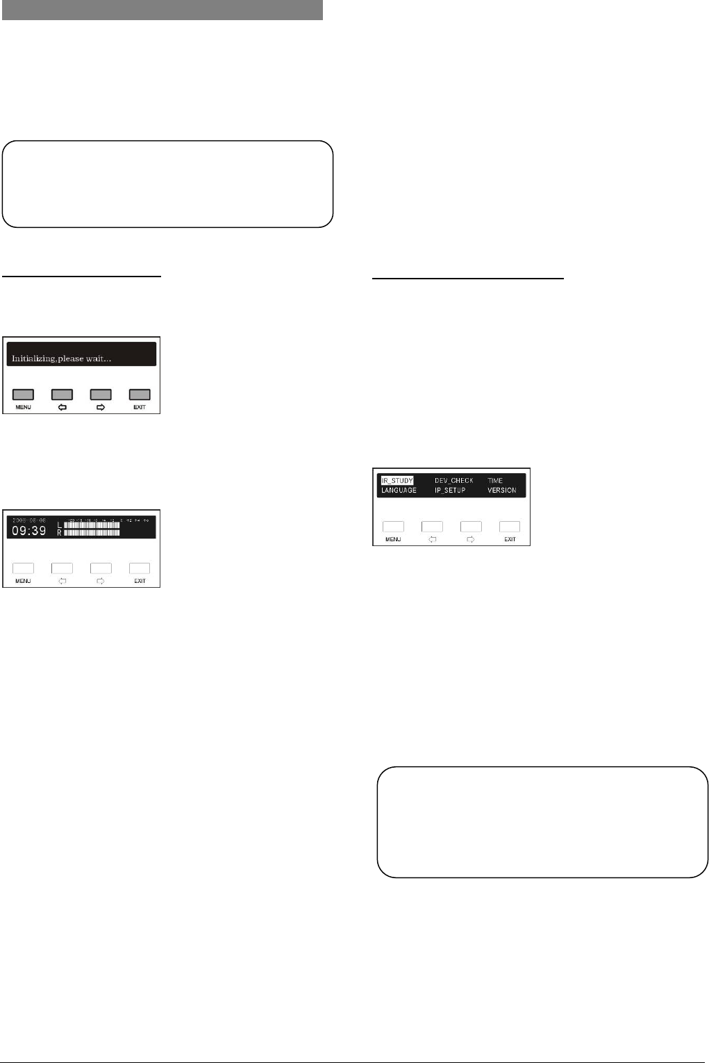
A) Starting initialization:
When switched on, HCS-6000MCP2 main unit starts
initialization.
After that, the LCD display shows:
y Date
y clock
y volume
Note:
) To come back to English version, please hold
the ”EXIT” button and switch on the main unit.
B) Accessing “Main” menu:
Press “MENU” button go to main menu, including 6
menu items:
“IR_Study”
“Device_check”
“Time”
“Language”
“IP_Setup”
“Version”
y Switch to desired menu item with “Õ/Ö” button,
selected item is highlighted;
y Press “MENU” button to go into corresponding
submenu;
y Use “EXIT” button to exit current menu and return
to upper level menu.
Pressing “EXIT” button under main menu will return to
central control system main unit start-up interface.
Note:
) All menu setup except “TIME” and “IP_SETUP”
use “MENU” button to exit saving changes, and
use “EXIT” to exit discarding changes.
22
3.5.1 IR learning
Before controlling IR devices, such as projector, DVD
player, PA and air condition, their IR code needs to be
learned by the central control system.
There are two methods to do IR learning.
Method 1: (detailed operation please refer to the user’s
manual of CS-IR manager)
y Setup the type, IR transmission port and key’s name
and amount through “CS-IR manager”;
y Do IR learning according to “CS-IR manager”
software menu operation;
y Create the IR code library of the device and save as
a file. The IR code library can be referred to by
“CS-logic programmer”;
y Programming the logic of the main unit with “CS-logic
programmer” and upload the compiled project file to
the main unit.
Method 2:
y Setup the type, IR transmission port and key’s name
and amount through “CS-IR manager” (detailed
operation please refer to the user’s manual of CS-IR
manager);
y Programming the logic of the main unit with “CS-logic
programmer” and upload the compiled project file to
the main unit.
y Do IR learning through menu operation of the main
unit front panel.
→ go to main menu
→ select “IR_STUDY” (the item is highlighted)
→ press “MENU” button to enter IR learning
“IR Learning” indicator lights up.
Operation:
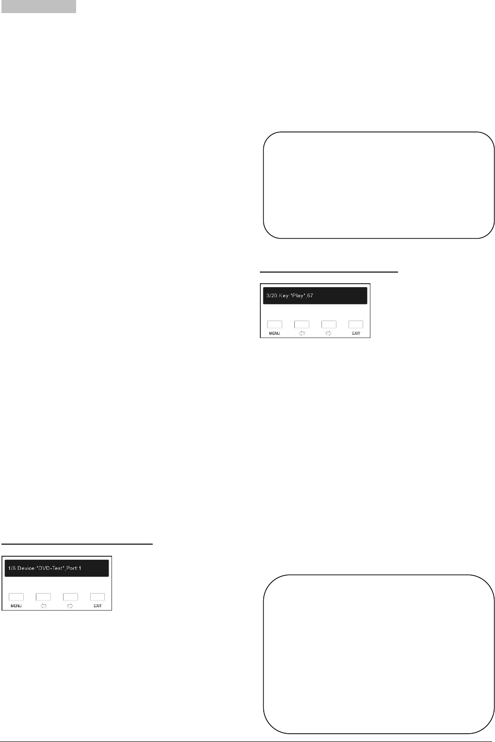
a) Select IR remote control device:
After selecting “IR_Study”, user interface shows the
above figure. The displayed data mean:
y 8 IR devices available in the project
y this is the 1st device
y the type/name of the device is “DVD”
y its IR port is ‘Port 1’.
Following:
y Press “Õ/Ö” button to skip the device and browse
other devices;
y Press “EXIT” button to exit IR learning;
y Or press “MENU” button to perform IR learning
(change all or parts of the IR codes of the device),
and enter the next step b).
Note:
b) Select IR remote control key:
After selecting IR remote control device, the remote
control key information of the current device is displayed
according to above figure. The displayed data mean:
y this IR device uses 20 remote control keys
y the current is the 3rd key
y its name is “Play”
y the length of the IR code is 67 (the valid pulse
number)
Following:
y Press “Õ/Ö” button to skip the current key and
browse other keys;
y Press “EXIT” button to exit IR learning;
y Or press “MENU” button to perform IR learning and
enter the next step c).
) The amount, type and button are user defined
and should coincide with the exact devices
used in your project. The maximum device
amount is 8 and the buttons for each device
are unlimited.
Note:
) Generally, the keys of a remote control have
identical IR code length. However, if the length
of a key’s IR code learnt is different from other
keys, it’s presumed that the learning fails and
needs relearning.
) Especially, among the IR control keys of the
projector, the length of common IR codes is
different from the mouse IR codes.
23
c) IR remote control key study:
After selecting the remote control key to study, a prompt
of reminding you to press the corresponding key will be
displayed and counted down for 10 seconds.
Following:
1). Aim the device’s remote controller at the IR learning
window on the front panel of main unit. The distance
should not exceed 20 cm;
2). Press the corresponding key within 10 seconds;
3). If the learning is successful, an indicating tone will be
given from central control system main unit and return
to select IR remote control key interface;
4). Repeat step 2~3 and study all other keys for the
current device;
5). Repeat step 1~3 and achieve all study process for all
devices.
If IR learning has carried out successfully the above
procedures, LCD prompts the dialog box as shown in the
figure below to exit IR_STUDY with or without saving the
settings, according to actual needs:
Following:
y Press “MENU” button to save the result and exit;
or
y Press “EXIT” button to quit without saving the result.
After quitting IR learning and returning to the main menu,
“IR Learning” indicator is switched off.
3.5.2 Device checking
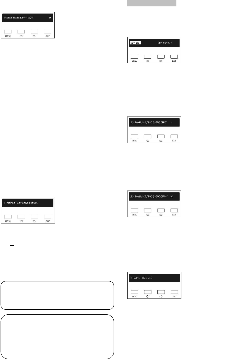
There are two sub-menus in “DEV_CHECK”:
“DEV_LIST”
“DEV_SEARCH”
“DEV_LIST”
“DEV_LIST” lists the information of network device and
touch panel configured in logic program. Once the
device list selected, the LCD displays the figure as
following:
Displayed data mean:
y wireless transceiver with NetId 1 configured in
logic program
y actual searching of the device is correct
Press the “Õ/Ö” button to continue.
Displayed data mean:
y HCS-6000PM power controller with NetId 2
configured in logic program
y but actual searching of the device fails.
Once the list passed through, the number of devices
configured in logic program is shown:
Note:
) The main unit neither accepts nor handles any
control signal.
Warning:
Press the “Õ/Ö” button again to show the wireless
touch panel configured in the project.
The LCD displays the figure as following:
) While saving the IR code do not power-down
the system, otherwise the IR code is corrupted
and the logic program must be downloaded
again from the computer.
24
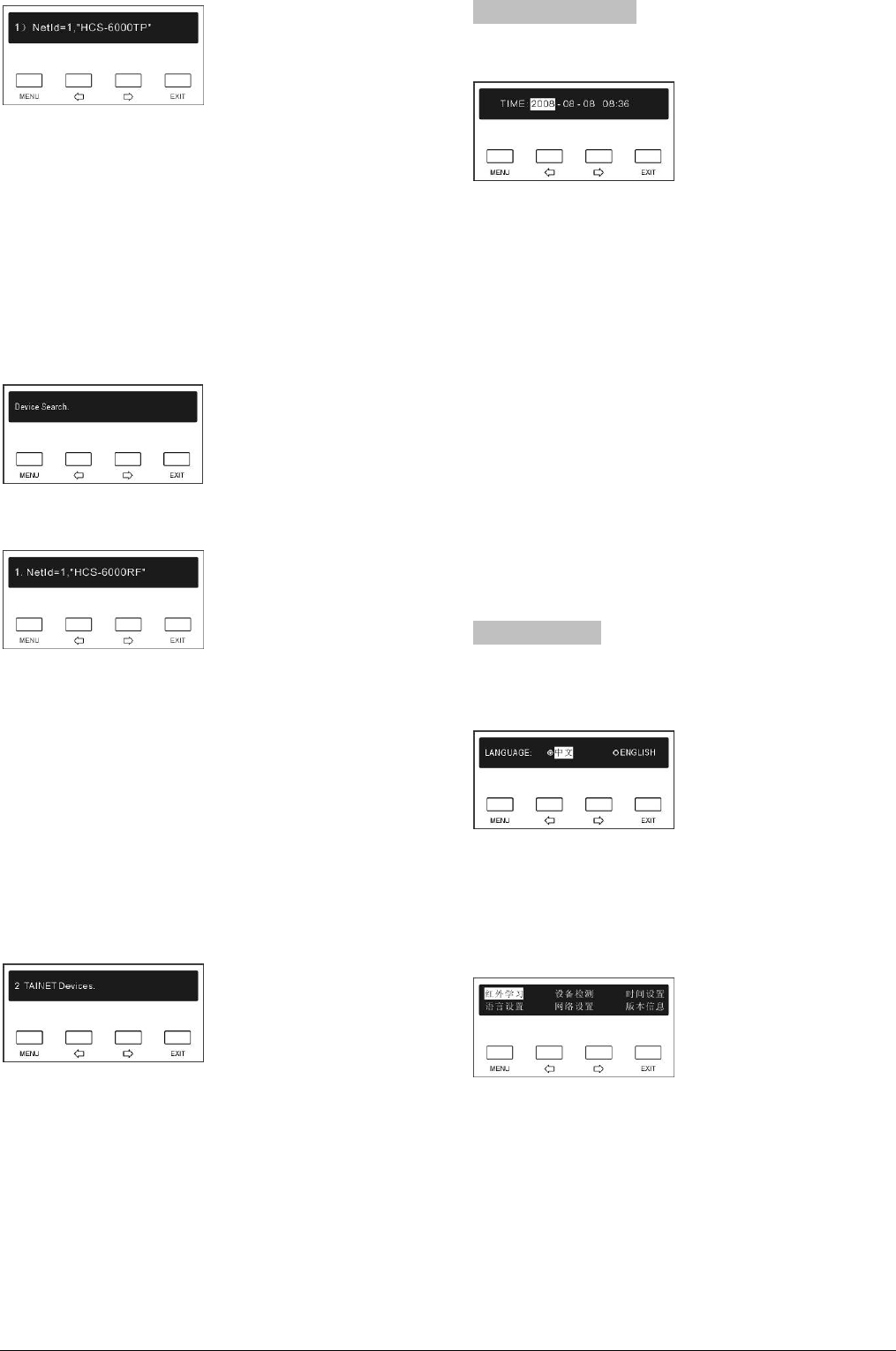
Displayed data mean:
y One wireless touch panel with RFId 1 configured in
the project.
“DEV_SEARCH”
“DEV_SEARCH” searches and reports the devices
actually connected to the TAINET network interface.
When the “DEV_SEARCH” is selected, press “MENU”
button to start the searching, LCD shows as follow:
If the TAINET device is found, LCD displays the figure as
following:
Displayed data mean:
y first device found with Netld = 1
y name of the first device is “HCS-6000RF”
Following:
y Press “EXIT” button to exit device searching and
return to main menu;
y Press other button to continue searching.
If the searching is finished, the LCD shows the statistical
data as follow:
Press any button to exit “DEV_SEARCH” and return to
main menu.
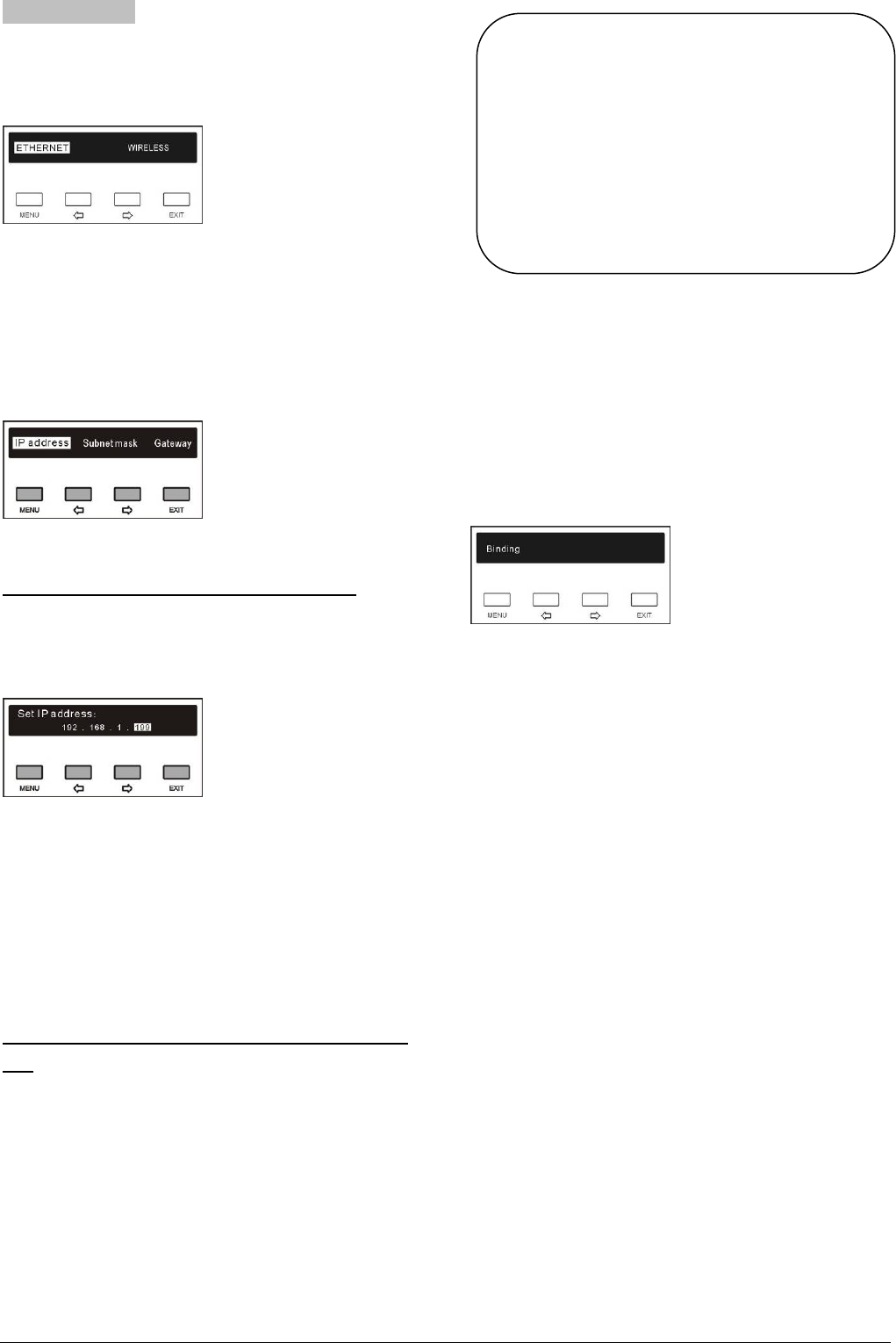
3.5.3 Time and date
The “TIME” menu is shown below:
Shows current system time: “2008-08-08 08:36”.
It can be modified by following steps:
1). Use “Õ/Ö” button to select the item of date
(year/month/day) or time (hour/minute) to be
changed;
2). Press “MENU” button to select the item and go to
compilation status;
3). Use “Õ/Ö” button to modify the item. Press and hold
“Õ/Ö” button for a longer time to change the number
quickly (= auto repeat);
4). After modification, press “EXIT” button to save and
exit;
5). Repeat step 1 ~ 3 to modify the rest; finally, press
“EXIT” to exit time menu.
3.5.4 Language
LCD menu has Chinese/English language options. The
“LANGUAGE” menu is shown below:
y Press “Õ/Ö” key to select the language;
y Press “MENU” button to confirm and exit.
y Press “EXIT” button to cancel selecting and exit.
The Chinese interface is as following figure:
25
3.5.5 IP_SETUP
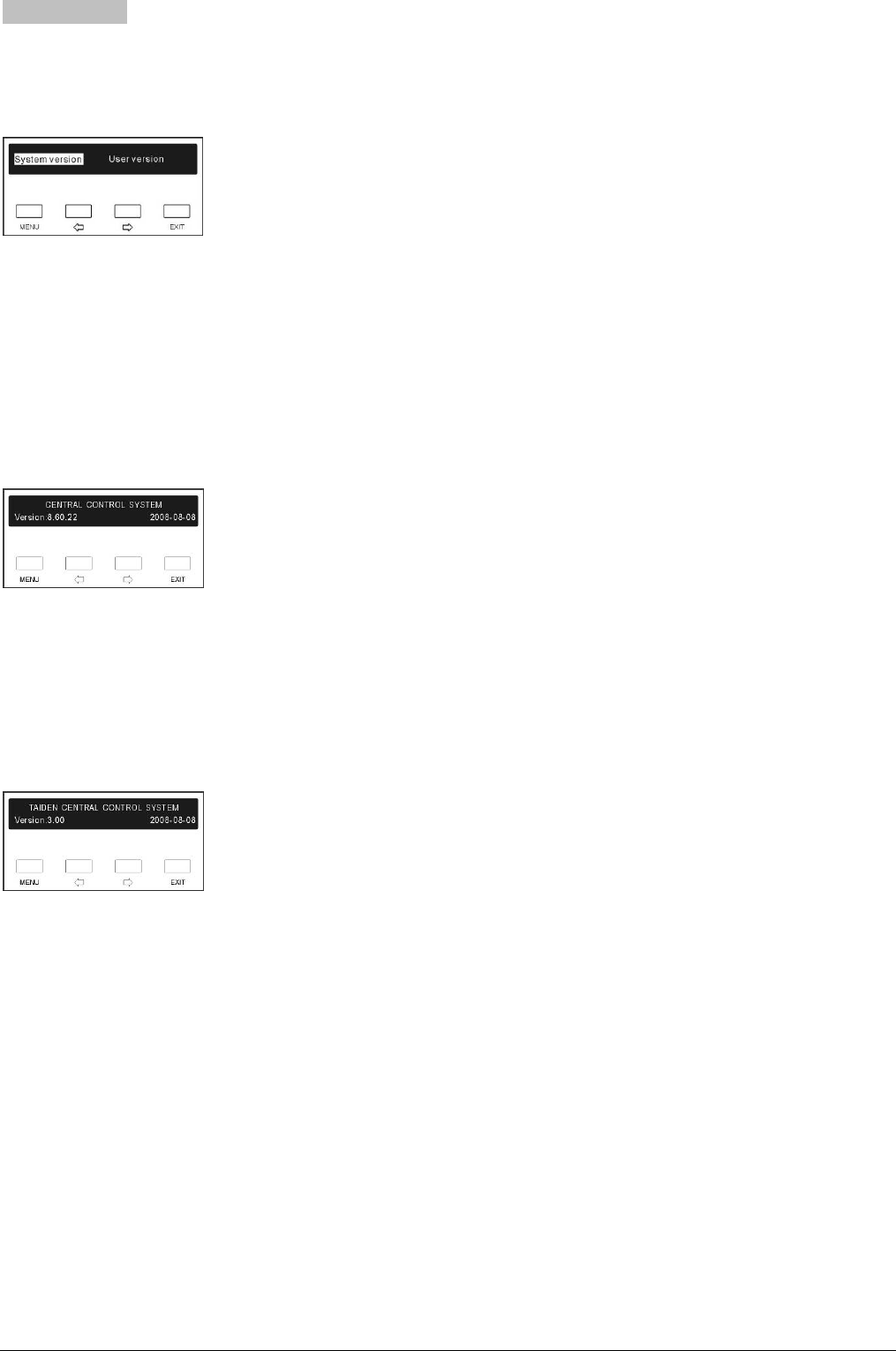
Two sub-menus are available in “IP_SETUP”:
“ETHERNET”
“WIRELESS”.
“ETHERNET”
“ETHERNET” includes three submenus:
“IP Address”
“Subnet Mask”
”Gateway”
a). Setup unique IP address for the main unit
To setup unique IP address for the main unit, select “IP
address”.
The LCD display is as following:
y Use “Õ/Ö” button to switch between the four
numbers;
y Use “MENU” button to edit selected number;
y Use “Õ/Ö” button to decrease/increase the
number. Press and hold “Õ/Ö” button for a longer
time to change the number quickly (= auto repeat).
y Use “EXIT” to return to high level menu.
b). Setup Subnetmask and Gateway for the main
unit
To setup “Subnetmask”, “Gateway” use the same
procedure as described in IP address.
Note:
) “IP address”, “Subnetmask” and “Gateway” of
the system software should accord with the
main unit, else connection error will occur.
) All menu setup except “TIME” and
“IP_SETUP” use “MENU” button to exit
saving changes, and use “EXIT” to exit
discarding changes
“WIRELESS”
The “Binding” function in “Wireless” is binding the
wireless touch panel again to the wireless transceiver,
if the working channel of the wireless transceiver was
changed.
Note: this function should be operated within 10
seconds after entering binding state (refer to section
2.4.3.1).
26
3.5.6 VERSION
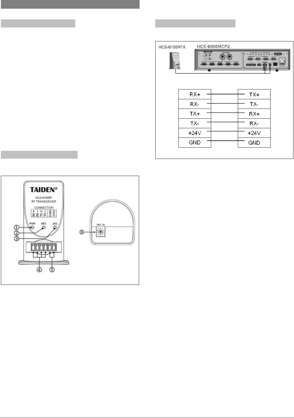
Two sub-menus are available in “VERSION”:
“System version”
“User version”
“System version”
“System version” shows the version information of the
system software (firmware program):
• version number
• creating time
The display is shown below:
The firmware program can be updated via COM port.
“User version”
“User version” shows the version information of the user
programming software (project logic configuration file);
The display is shown below:
As the example shows, the project name is “TAIDEN
CENTRAL CONTROL SYSTEM”; the version no. is
“3.00”, and the last update time is 08/08/2008.
27

29
3.7 Application examples of related software
3.7.1 CS-Logic programmer
All control interfaces and modes of HCS-6000MCP2
intelligent central control system are provided with open
set-up environment; user can program each control port
and set various control protocols to communicate with
various controlled devices.
HCS-6000MCP2 software is a visualized develop
environment for the user. The specific programming
software “CS-Logic Programmer” (available on the
documentation CD-ROM) provides a flexible
programming method to program the control interface of
HCS-6000MCP2 in graphics mode and uses specific
control protocols and instructions for device control.
(Refer to “CS-Logic programmer” instructions for
details)
After HCS-6000MCP2 programming, the compiled
program is to be uploaded to HCS-6000MCP2. (Refer to
section 3.6.2 - “File transfer”)
3.7.2 CS-IR manager
“CS-IR Manager” is a specific IR code management
software (available on the documentation CD-ROM); it
can be used for cooperating with HCS-6000MCP2
programming software or for independent use.
TAIDEN “CS-IR Manager” is provided with the related
management facilities of IR codes, including IR
learning, storage, management and generating valid IR
code library for the specific electric equipment. The IR
code library can be saved as a file.
The IR code library can be referred to by the
HCS-6000MCP2 programming software, through
software menu operation of “User device library – IR
device”.
Chapter 4. Network peripheral devices
4.1 Wireless transceiver
4.1.1 Function introduction
HCS-6100RFS/RFX wireless transceiver cooperates
with wireless touch panel to achieve 1-way/2-way
wireless controlling. Wireless transceiver receives the
RF signal from the wireless touch panel and transmits
the received data to the central control main unit via the
TAINET network; at the same time, the 2-way
transceiver feeds back status of the main unit to the
touch panel and achieves 2-way controlling.
HCS-6100RFS/RFX wireless transceiver works at ISM
frequency band 2.4 GHz, which can be freely used
worldwide.
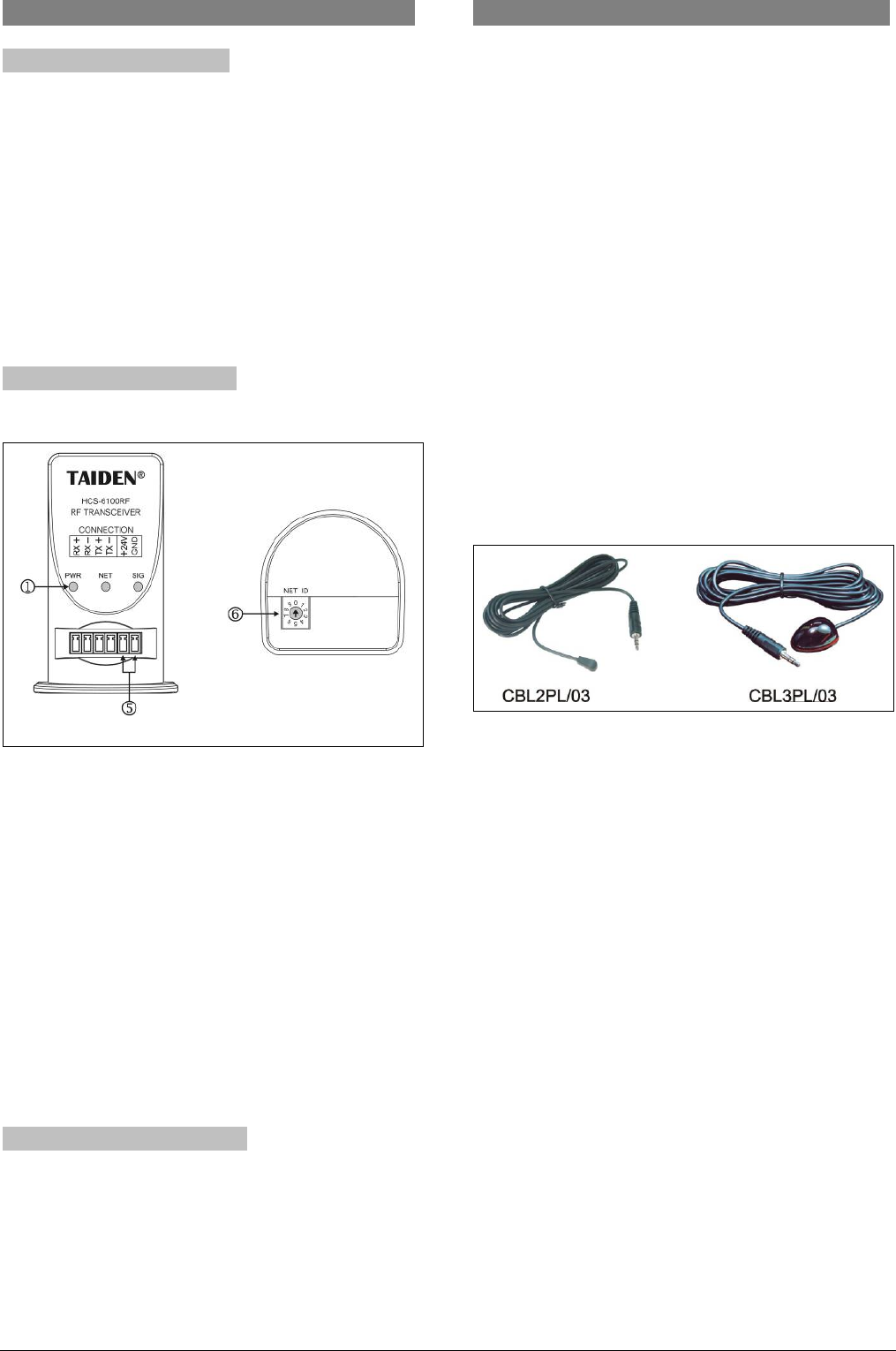
4.1.2 Interface and indicator
front rear
Figure 4.1 HCS-6100RFS/RFX wireless transceiver
Figure 4.1:
1. Power indicator
Illuminated when power supply connected
2. Network indicator
3. RF signal indicator
4. Data interface
Connecting wireless transceiver to central control
system main unit
5. Power supply interface
Supplies power to wireless transceiver
6. RF channel selector
Wireless frequency setup of wireless transceiver
4.1.3 Connection explanation
HCS-6100RFX HCS-6000MCP2
Figure 4.2 wireless transceiver connection to main
unit
30
4.2 Wireless Router
4.2.1 Function introduction
HCS-6100RF/ROUTER wireless router is used for
extending the reception distance of the wireless
transceiver.
If the touch panel temporarily works and hangs up, the
distance between the touch panel and the transceiver
is too large. Install a wireless router between the touch
panel and the wireless transceiver to have interruption-
free operation.
4.2.2 Interface and indicator
front rear
Figure 4.3 HCS-6100RF/ROUTER wireless router
Figure 4.3:
1. Power indicator
Illuminated when power supply connected.
5. Power supply interface
Supplies power to HCS-6100RF/ROUTER.
6. RF channel selector
For HCS-6100RF/ROUTER wireless frequency
setup. The router function will work only when this
frequency coincidences both with the frequencies of
the wireless transceiver and touch panel.
4.2.3 Connection explanation
y DC + 5 ~ + 24 V from external source
or
y From the main unit by connecting the
corresponding interface.
4.3 IR transmission stick
CBL2PL/03 and CBL3PL/03 IR transmission sticks are
suitable IR transmission devices with 3-meter-long
cable. Matches central control system main unit to
achieve IR remote controlling for projector, DVD, PA,
air condition etc.
To operate, first plug the connector of the IR
transmission stick into the IR OUTPUT socket on the
main unit. Following, place the IR transmission
terminator directly in front of the IR reception window of
the controlled device. The distance should not exceed
20 cm.
After IR learning procedure (5.3.1), the corresponding
IR device can be controlled by operating the IR remote
controller directly in front of the IR receiving window on
the front panel.
Figure 4.4 HCS-6100 IR transmission stick
31
4.4 Lighting controller
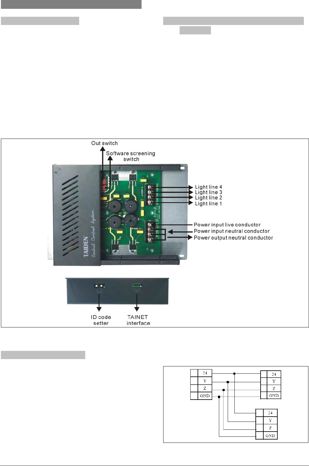
4.4.1 Function introduction 4.4.2 Internal wiring & debugging switch
illustration
The 4-way incandescent arc lamp lighting modules are
used to control the luminance of incandescent lamps
(4-way independent control or integrated control as
option).
Output switch:
• switch=ON Æ output of the corresponding line = ON
• switch=OFFÆoutput of the corresponding line = OFF
Connection to the main unit is made by using the
TAINET port at the rear side. Each device must have a
unique ID number if operated in the same network.
Software screening switch with output switch =
ON:
y screening switch = OFFÆ output lighting of the
corresponding line is controlled by software.
y screening switch = ON Æ output lighting of the line is
at its maximum and is independent of the software.
Figure 4.5 HCS-6000LM lighting controller
4.4.3 Connection explanation
If HCS-6000LM lighting controller is connected to the
main unit via the 4-pin (24, Y, Z, G) network interface, be
sure that each pin is connected to the relevant pin on the
main unit; if multiple HCS-6000LM are operated, connect
as shown in following figure:
Figure 4.6 TAINET devices connect to main unit
32
4.5 Power controller
4.5.1 Function introduction
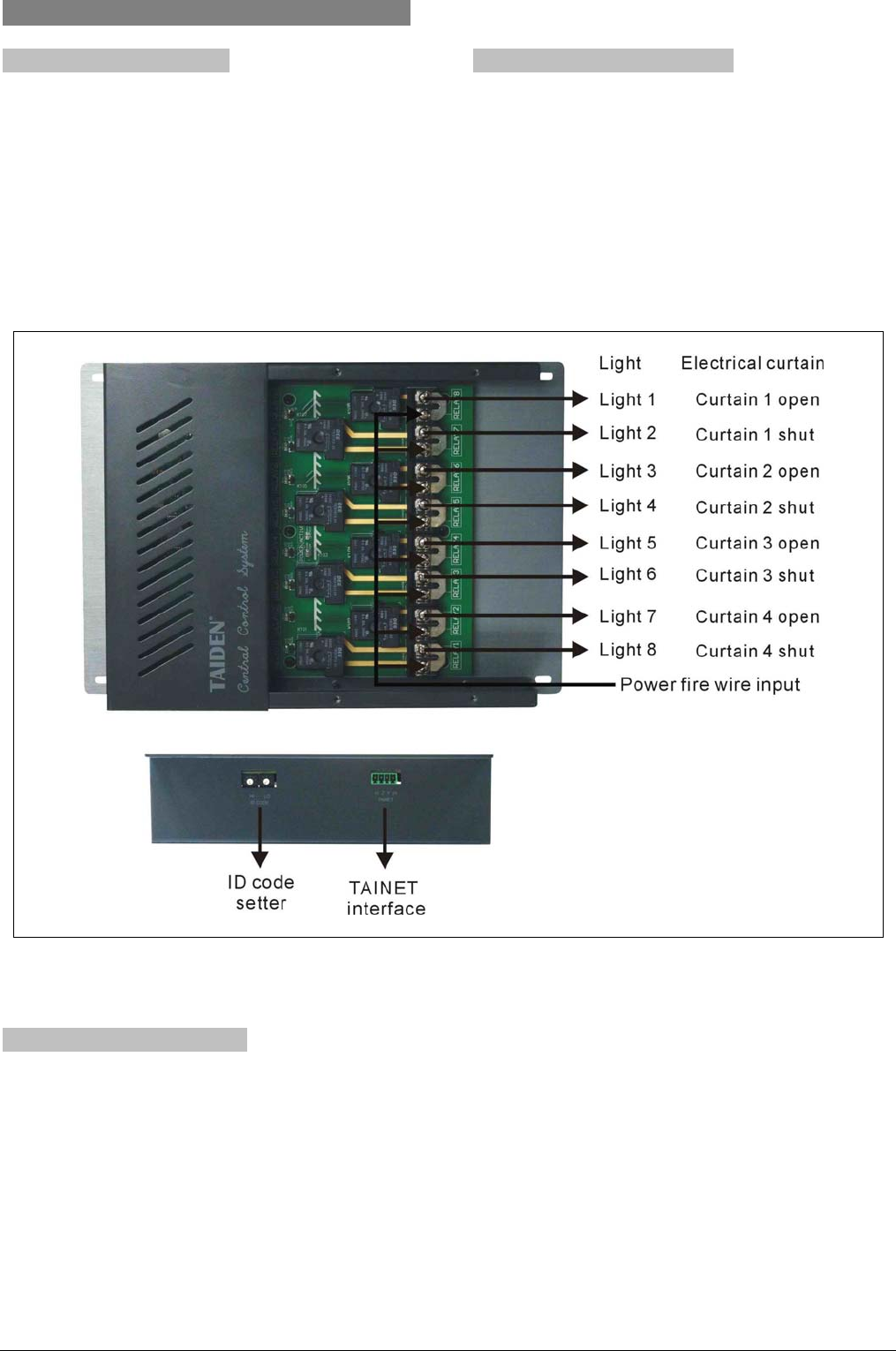
HCS-6000PM is a high current power controller
cooperated with HCS-6000M main unit to control power
supply for lightings, electrical curtain, electrical screen
and projector etc. It features 8 high current relays for a
maximum load current of 30 A each.
4.5.2 Internal wiring illustration
The following load can be connected to HCS-6000PM
power controller:
(1) 8 independent switch controls;
(2) 4 electrical curtain switches;
(3) Other composition within the controllable scope
(e.g. 1 electrical curtain + 6 independent switches
or 2 electrical curtains + 4 independent switches)
Figure 4.7 HCS-6000PM power controller
4.5.3 Connection explanation
If HCS-6000PM power controller is connected to the
main unit via the 4-pin (24, Y, Z, G) network interface, be
sure that each pin is connected to the relevant pin on the
main unit; if multiple HCS-6000PM are operated,
connect as shown in figure 4.6.
33
4.6 Intelligent Wall-mounted Keypad
4.6.1 Function introduction
There are 4 types of HCS-6000SW series intelligent
wall-mounted keypad: 2, 4, 8, 12 keys, to interact with
HCS-6000M main unit. Function and logic are
programmable, applicable for scene preset, controlling
light, air condition, electric curtain, electric screen and
projector.
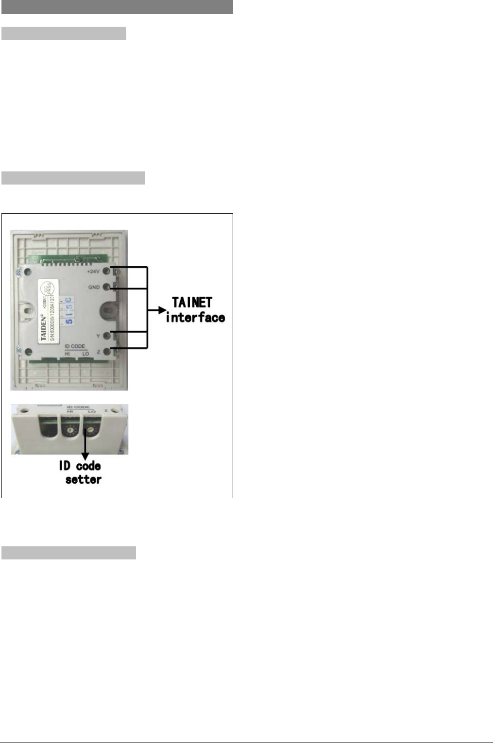
4.6.2 Internal wiring illustration
Figure 4.8 HCS-6000SW intelligent wall-mounted keypad
4.6.3 Connection explanation
If HCS-6000SW intelligent wall-mounted keypad is
connected to the main unit via the 4-pin (24, Y, Z, G)
network interface, be sure that each pin is connected to
the relevant pin on the main unit; if multiple
HCS-6000PM are operated, connect as shown in figure
4.6.
34

Chapter 5. Fault diagnosis
Fault Solution
Touch panel cannot power on
Possibly caused by low battery, please plug-in the adaptor and
charge the battery.
Black screen
Possibly because touch panel is in standby or power off state. Touch
the screen to activate it and make sure that the battery or the power
supply is connected.
Touch panel displays but cannot achieve
controlling
If the touch panel drifts, please go to touch panel setup interface and
do calibration.
When wired connection, note that the remote IP address must
coincide with the address of the central control system main unit.
When wireless connection, note that the RF ID of the touch panel
must coincide with the ID in the program.
When wireless connection, note that the channel configuration of the
touch panel must coincide with the configuration of 6100RF.
“TAINET” indicator doesn’t light up when button
of touch panel is pressed.
Wrong RF ID for HCS-6000TP. Set the actual RF ID of HCS-6000TP
to accord with the value set in logic program.
“TAINET” indicator lights up but ”EXECUTE” and
“LAN” indicators are off when button of touch
panel is pressed.
Logic program has error or does not accord with touch panel interface
program. Check the logic program and touch panel interface program
Cannot start unit, the power indicator is off
The power socket isn’t properly plugged. Properly plug the mains plug
to the socket.
Cannot start unit, the power indicator is on. (The
buzzer beeps sometimes)
The interval between the restart and last power down is too short. The
interval should be at least 5 seconds.
TAINET network devices are not under control of
the main unit control (the “EXECUTE” indicator is
on when under control)
TAINET network device’s NET ID is wrong. Set the TAINET device’s
NET ID to accord with the logic program.
TAINET network connection with a multitude of
devices; some are uncontrollable while
controlling a single device works normally.
Double assignment of NET IDs in TAINET devices. Change the
device’s NET ID.
No voice output
Input volume is too low. Increase input volume.
Master volume is too low. Increase master volume.
Under MUTE state. Release from MUTE state.
IR control facility is abnormal
IR transmission stick isn’t aimed at the IR receiving window of the
controlled device. Aim the stick at the controlled device, with a
distance less than 20 cm.
The IR learning port does not accord with the port of the IR stick.
Make sure the two ports are in accordance.
The IR codes learnt are invalid. Learn the previously incorrect IR
buttons again, following the steps of IR learning strictly.
“PWR” indicator of HCS-6100RF does not light
up
Check the power cord between RF transceiver and main unit.
The “SIG” indicator of HCS-6100RF is abnormal
when button of touch panel is pressed.
RF interference source(s) nearby. Remove the interference source(s).
36

Chapter 6. Technical data
6.1 System specification
System environmental conditions
Working conditions fixed/stationary/transportable
Temperature range:
- Transport: -40 °C to +70 °C
- Operating: 0 °C to +45 °C
Max. Relative humidity: < 95% (not condensing)
Safety: Compliant to EN 60065
EMC approvals: CE
37
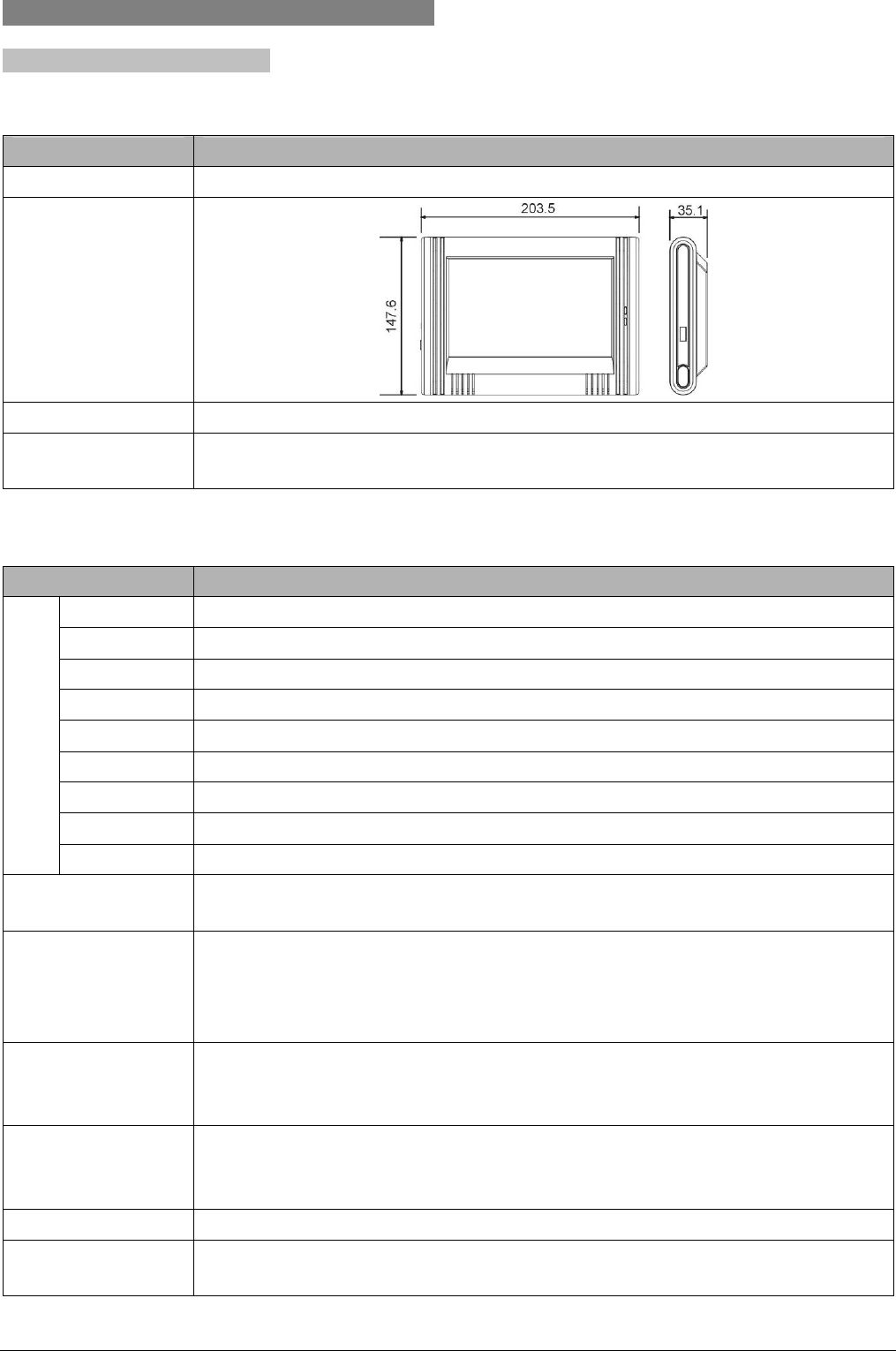
6.2 Widescreen touch panel and accessory
6.2.1 7" widescreen touch panel
6.2.1.1 Physical characteristics
Type HCS-6107TP/TPX
Installation Tabletop/Portable
Dimension
(mm)
Color Black/Gray
Weight 0.72 kg(incl. Battery, excl. portable base plate)
1.41 kg(incl. battery and portable base plate)
6.2.1.2 Electrical characteristics
Type HCS-6107TP/TPX
Type True color TFT LCD
Dimension 7 inches
Aspect Ratio 16:9
Resolution 800×480
Brightness 300 cd/m2
Contrast 500
Dot pitch 0.1905×0.1905 mm
Color 218 (18 bit)
LCD
Standard PAL/NTSC
Power 11.1 V DC (HCS-6107BAT rechargeable Lithium-lon battery)
15 V DC (HCS-ADP15V adapter)
Battery working time
Continuous working duration: approx. 6 hours (the screen is continuously on)
Normal working duration: approx. 7 days
(related to the settings of power management and luminance)
Standby time: approx. 80 days
Current
Normal working current: 350 mA ~ 400 mA
Standby current: 100 mA ~ 120 mA
Power-off current: 1 mA ~ 1.5 mA
Wireless
transmission
parameters
Working frequency: 2.4 GHz
Effective range: > 25 meters
Memory 64 MB SDRAM,64 MB Flash
Other parameters digital button≤4000, analog button ≤1000
ID range of RF: 0~9, button ID number: 0001~4000
38
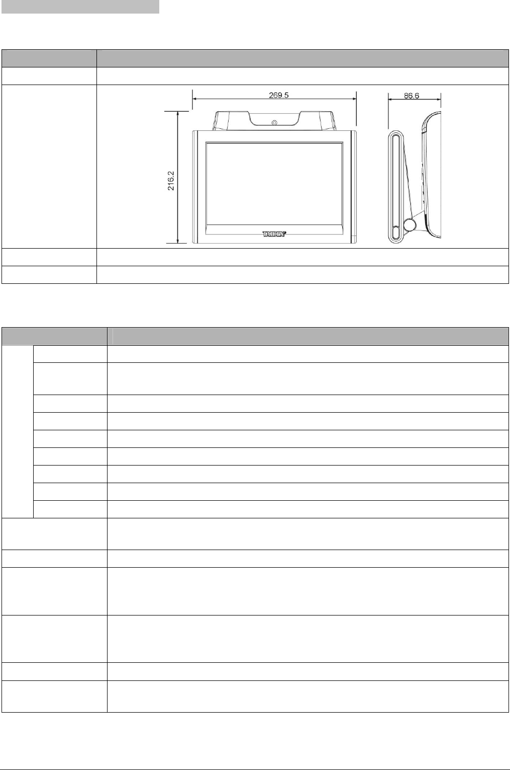
6.2.2 10" widescreen touch panel
6.2.2.1 Physical characteristics
Type HCS-6110TP/TPX
Installation Tabletop
Dimension
(mm)
Color Black/Gray
Weight 2.34 kg
6.2.2.2 Electrical characteristics
Type HCS-6110TP/TPX
Type True color TFT LCD
Dimension
10.2 inches
Aspect Ratio 16:9
Resolution 800×480
Brightness 400 cd/m2
Contrast 400
Dot pitch 0.2775×0.2775 mm
Color 218 (18 bit)
LCD
Standard PAL/NTSC
Power 16 V/19 V DC (HCS-6110BAT rechargeable Lithium-lon battery)
15 V DC (HCS-ADP15V adapter)
Battery working time Continuous working duration: approx. 4~4.5 hours (the screen is continuously on)
Current
Normal working current: approx. 800 mA
Standby current: 100 mA ~ 120 mA
Power-off current: 1 mA ~ 1.5 mA
Wireless
transmission
parameters
Working frequency: 2.4 GHz
Effective range: > 25 meters
Memory 64 MB SDRAM,64 MB Flash
Other parameters digital button≤4000, analog button ≤1000
ID range of RF: 0~9, button ID number: 0001~4000
39
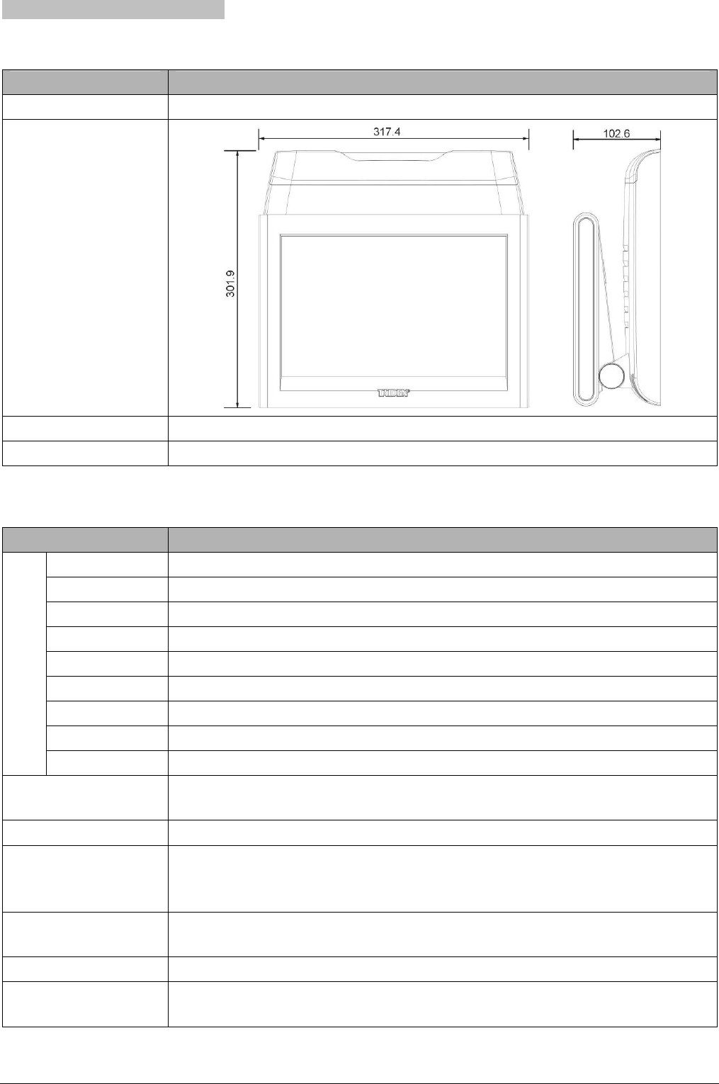
6.2.3 12" widescreen touch panel
6.2.3.1 Physical characteristics
Type HCS-6112TP/TPX
Installation Tabletop
Dimension
(mm)
Color Black/Gray
Weight 3.87 kg
6.2.3.2 Electrical characteristics
Type HCS-6112TP/TPX
Type True color TFT LCD
Dimension 12.1 inches
Aspect Ratio 16:9
Resolution 1280×800
Brightness 200 cd/m2
Contrast 500
Dot pitch 0.204×0.204 mm
Color 218 (18 bit)
LCD
Standard PAL/NTSC
Power 16 V/19 V DC (HCS-6110BAT rechargeable Lithium-lon battery)
15 V DC (HCS-ADP15V adapter)
Battery working time Continuous working duration: approx. 4 hours (the screen is continuously on)
Current
Normal working current: 820 mA~870 mA
Standby current: approx. 350 mA
Power-off current: 1 mA ~ 1.5 mA
Wireless transmission
parameters
Working frequency: 2.4 GHz
Effective range: > 25 meters
Memory 64MB SDRAM,64MB Flash
Other parameters digital button≤4000, analog button ≤1000
ID range of RF: 0~9, button ID number: 0001~4000
40
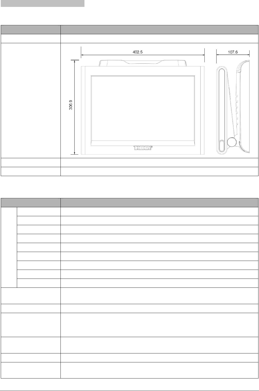
6.2.4 15" widescreen touch panel
6.2.4.1 Physical characteristics
Type HCS-6115TP/TPX
Installation Tabletop
Dimension
(mm)
Color Black/Gray
Weight 4.61 kg
6.2.4.2 Electrical characteristics
Type HCS-6115TP/TPX
Type True color TFT LCD
Dimension 15.4 inches
Aspect Ratio 16:9
Resolution 1280×800
Brightness 200 cd/m2
Contrast 300
Dot pitch 0.2587×0.2587 mm
Color 218 (18 bit)
LCD
Standard PAL/NTSC
Power 16 V/19 V DC (HCS-6110BAT rechargeable Lithium-lon battery)
15 V DC (HCS-ADP15V adapter)
Battery working time Continuous working duration: approx. 3.5 hours (the screen is continuously on)
Current
Normal working current: 970 mA~1020 mA
Standby current: approx. 380 mA
Power-off current: 1 mA ~ 1.5 mA
Wireless transmission
parameters
Working frequency: 2.4 GHz;
Effective range: > 25 meters
Memory 64MB SDRAM,64MB Flash
Other parameters digital button≤4000, analog button ≤1000
ID range of RF: 0~9, button ID number: 0001~4000
41
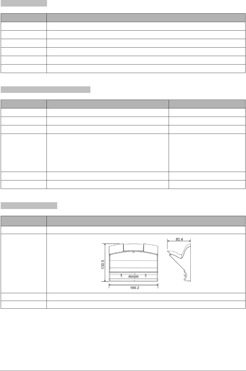
6.2.5 Power Adapter
Type HCS-ADP15V
Mains voltage 100 V ~ 240 V AC, 50 Hz /60 Hz
Output 15 V DC, 2.2 A
Cable length 3 m
Dimension 95 (w) x 28 (h) x 45(d) mm
Color Black
Weight 0.3 kg
6.2.6 Rechargeable Lithium-lon Battery
Type HCS-6107BAT HCS-6110BAT
Nominal voltage 11.1 V 16 V / 19 V
Nominal capacity 2400 mAh 48.8 Wh
Charging time 2.5 ~ 3 hours 3.5 ~ 4 hours
Working duration
Continuous working duration: approx. 6 hours (the screen
is continuously on)
Normal working duration: approx. 7 days (related to the
settings of power management and luminance)
Standby time: approx. 80 days
Depending on the touch panel type
Color Black/Gray Black
Weight 0.2 kg 0.42 kg
6.2.7 Portable base plate
Type HCS-6107BKT
Installation Tabletop
Dimension
(mm)
Color Black/Gray
Weight 0.69 kg
42
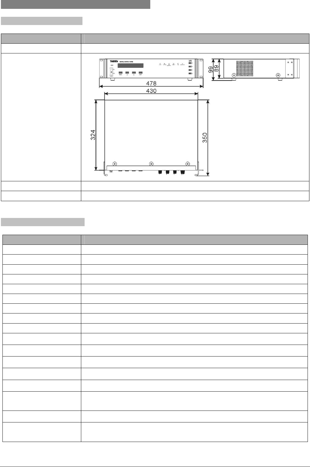
6.3 Main unit
6.3.1 Physical characteristics
Type HCS-6000MCP2
Installation Tabletop/19 inch rack
Dimension
(mm)
Color White
Weight 7.5 kg
6.3.2 Electrical characteristics
Type HCS-6000MCP2
Audio gain 0 dB
Frequency range 20 Hz ~ 20 kHz +0/-0.5dB (1 kHz reference)
S/N ratio ≥92dB
Crosstalk attenuation ≥80 dB
Total harmonic distortion ≤0.01% (1 kHz)
Input impedance ≥10 kΩ
Output impedance ≤10 Ω
Max. input level 7 Vrms
Max. output level 7 Vrms
TAINET 1 TAINET 4-pin interface
TO COMPUTER RS-232C, DB9F
IR OUTPUT 8 IR transmission ports
I/O PORT 8 programmable digital I/O ports
RELAY 4 low relays (0.3 A/125 V-AC, 1 A/30 V-DC)
COM PORT (RS-232C) 8 DB9 serial ports, RS-232 (1) ~ (3) are 1-way ports, RS-232(4) ~ (8) are 2-way ports.
(RS-232C, max. baud rate 115,200 bps)
ETHERNET RJ45 (RS-485) network interface
POWER America, Japan: AC 110 V~120 V 60 Hz (FUSE 5 A/250 V)
Asia, Europe: AC 220 V~240 V 50 Hz (FUSE 2 A/250 V)
0 dBu = 0.775 Vrms
43
6.4 Network peripheral devices
6.4.1 Wireless transceiver and wireless router
100 m wireless RF(2.4 GHz) range
1-way/2-way wireless transceiver
Dimensions L×W×H (mm): 83×50×50
6.4.2 Lighting controller
4 controllable lighting interfaces
Power supply: 220 V 50 Hz;
ID select: via ID setup rotary switches (HI/LO)
Independent network protocol control
Single line or multiple line controllable
For connection to HCS-6000M series intelligent
central control system main unit
Load capacity: power (single line) ≤1500 W;
power (total) ≤5000 W;
The actual load power must be below this maximum
value! The wiring for connection must be designed
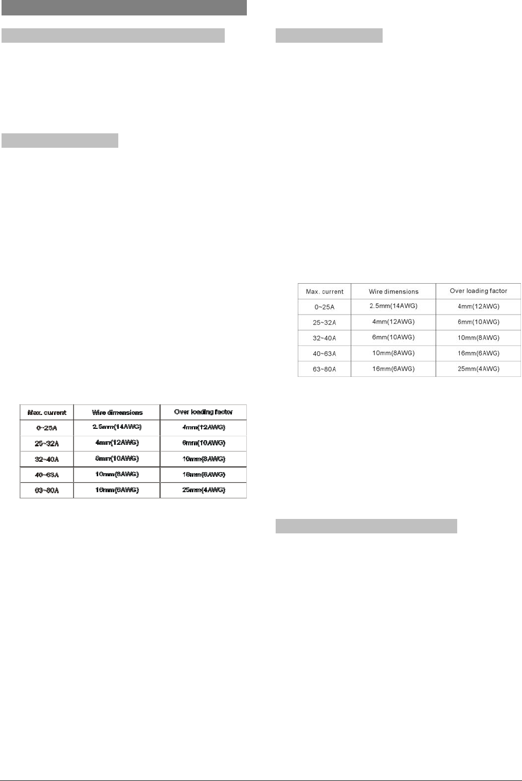
for the requirement of max. current. The table below
shows the relations between wire dimensions and
max. safe current (excerpt from the table 11 of IEC
60950).
Note: in some countries or regions, the over loading
factor is required for wiring. For safety purposes,
TAIDEN recommends to use only the overload cable
version for your max. current. (Example: 12 AWG for 0
to 25 A)
Installation requirement: The mounting of the device
should be well grounded using a PE (protective
grounding) wire whose dimensions and insulation
material are equivalent to that of the branch power
line. The PE insulation wire should be a green wire
with yellow stripe. The grounding wire is used to
connect device to the building floor.
Dimensions L×W×H (mm): 320×221×66
Weight: 2.5 kg
6.4.3 Power controller
8 independent power switch controls
ID select: via ID setup rotary switches (HI/LO)
Power supply: 24 VDC, supplied by TAINET network
Independent network protocol control
Single or multiple line switch
For connection to HCS-6000M series intelligent
central control system main unit
Load capacity: single line 20 A;
The actual load power must be below this maximum
value. The wiring for connection must be designed
for the requirements of max. current. The figure
below shows the relations between wire dimensions
and max. safe current (excerpt from the table 11 of
IEC 60950).
Note: in some countries or regions, the over loading
factor is required for wiring. For safety purposes,
TAIDEN recommends to use only the overload cable
version for your max. current. (Example: 12 AWG for 0
to 25 A)
Dimensions L×W×H (mm): 320×221×66
Weight: 2.7 kg
6.4.4 Intelligent wall-mounted keypad
Communication method: TAINET Control BUS
ID select: via ID setup rotary switches (HI/LO)
Button number: 2/4/8/12 respectively
Command programming: user-defined command
code by programming software
Connection port: TAINET BUS
Power supply: 24 V DC, supplied by TAINET
network
Dimensions L×W×H (mm): 86×119×11
Color: White
44
