User Manual
Test Item Anti-Theft Gate
Model TS-A1-FCC
Date 2014/9/5
Ref TDR-MNL-TS-A1-FCC-100
Rev 1.00

Model Name: TS-A1-FCC
2 / 10
仕様書番号: TDR-MNL-TS-A1-FCC-100
Table
Table Table
Table of contents
of contentsof contents
of contents
1
11
1
Regulations and Standards
Regulations and StandardsRegulations and Standards
Regulations and Standards
................................
................................................................
................................................................
................................................................
...........................................................
......................................................
...........................
3
33
3
1.1
FCC ..................................................................................................................................................... 3
1.2
FCC
NOTICE ........................................................................................................................................ 3
1.3
FCC
WARNING ..................................................................................................................................... 3
1.4
W
ASTE
.................................................................................................................................................. 3
2
22
2
INTRODUCTION
INTRODUCTIONINTRODUCTION
INTRODUCTION
................................
................................................................
................................................................
................................................................
................................................................
................................................................
.........................................
..................
.........
4
44
4
3
33
3
Safety Precautions
Safety PrecautionsSafety Precautions
Safety Precautions
................................
................................................................
................................................................
................................................................
................................................................
................................................................
.....................................
..........
.....
5
55
5
4
44
4
Genera
GeneraGenera
General Specifications
l Specificationsl Specifications
l Specifications
................................
................................................................
................................................................
................................................................
................................................................
................................................................
.................................
..
.
6
66
6
4.1
N
AMES OF EACH PART
............................................................................................................................. 6
4.2
P
RODUCT
S
PECIFICATIONS
....................................................................................................................... 7
4.3
A
NCHOR BOLTS
...................................................................................................................................... 7
4.4
E
XTERIOR DIMENSION
............................................................................................................................... 8
4.5
B
OTTOM BASE
........................................................................................................................................ 9
5
55
5
Revised history
Revised historyRevised history
Revised history
................................
................................................................
................................................................
................................................................
................................................................
................................................................
.........................................
..................
.........
10
1010
10

Model Name: TS-A1-FCC
3 / 10
仕様書番号: TDR-MNL-TS-A1-FCC-100
1
11
1 Regulations and Standards
Regulations and StandardsRegulations and Standards
Regulations and Standards
1.1
1.11.1
1.1 FCC
FCCFCC
FCC
This product is conformed to the FCC standards.
FCC Rules ( Federal Communications Commision )
This product complies with Part 15 Subpart B and C of the FCC Rules.
FCC ID : MK4TS-A1-FCC
This device complies with Part 15 of the FCC Rules. Operation is subject to the following two
conditions:
(1) this device may not cause harmful interference, and
(2) this device must accept any interference received, including interference that may cause
undesired operation.
1.2
1.21.2
1.2 FCC NOTICE
FCC NOTICEFCC NOTICE
FCC NOTICE
This equipment has been tested and found to comply with the limits for a Class B digital device,
pursuant to part 15 of the FCC Rules. These limits are designed to provide reasonable protection
against harmful interference in a residential installation. This equipment generates, uses and can
radiate radio frequency energy and, if not installed and used in accordance with the instructions,
may cause harmful interference to radio communications. However, there is no guarantee that
interference will not occur in a particular installation. If this equipment does cause harmful
interference to radio or television reception, which can be determined by turning the equipment off
and on, the user is encouraged to try to correct the interference by one or more of the following
measures:
- Reorient or relocate the receiving antenna.
- Increase the separation between the equipment and receiver.
- Connect the equipment into an outlet on a circuit different from that to which the receiver is
connected.
- Consult the dealer or an experienced radio/TV technician for help.
1.3
1.31.3
1.3 FCC WARN
FCC WARNFCC WARN
FCC WARNING
INGING
ING
Changes or modifications not expressly approved by the party responsible for compliance could void
the user’s authority to operate the equipment.
1.4
1.41.4
1.4 Waste
WasteWaste
Waste
EU RoHS Supported.
Dispose of the Products as industrial waste.

Model Name: TS-A1-FCC
4 / 10
仕様書番号: TDR-MNL-TS-A1-FCC-100
2
22
2 INTRODUCTION
INTRODUCTIONINTRODUCTION
INTRODUCTION
Introduction to Radio Frequency Electronic Article Surveillance ( RF-EAS )
The TAKAYA EAS system is composed of sensing pedestals, some that transmit a frequency signal
and others that receive the signal. When a RF tag passes between the transmitter and receiver, an
alarm sounds. This alerts store personnel that store items are leaving the premises with a live RF
tag. Often, the very presence of the pedestals will be enough to deter a potential shoplifter.
Merchandise in the store is tagged with hard tags or labels. During a normal transaction, the
cashier will pass the merchandise over a deactivation Pad or scanner integrated with deactivation
electronics. This deactivation field turns off the signal contained in the tag. Customers may now
exit the store without causing the system to alarm. For those stores using hard tags to protect
clothing or other soft goods, the tag is removed at the point of sale so that the customer may exit the
store without alarming the system.
TAKAYA EAS system minimizes the opportunity for shoplifters to successfully steal merchandise.
In addition to the physical deterrence the sensing pedestals provide, hard tags and labels offer
hidden protection. Because TAKAYA EAS offers such a wide variety of tags, shoppers are often
unaware that merchandise is protected against shoplifting. This way, shoplifters cannot leave the
store premises with merchandise that has not been properly paid for. In conclusion, the TAKAYA
EAS provide:
• Deterrence - the pedestals’ presence discourages shoplifting attempts by customers, vendors, and
employees
• Protection - provided by the various tags, and program
• Detection - reinforces the risk of shoplifting while searching for non-deactivated/non-detuned “live”
disposable tags or non-removed hard tags
Model Name: TS-A1-FCC
5 / 10
仕様書番号: TDR-MNL-TS-A1-FCC-100
3
33
3 Safety Precautions
Safety PrecautionsSafety Precautions
Safety Precautions
The following symbols are used in this manual to indicate precautions that must be observed to
ensure safe use of this product. The precautions provided here contain important safety information.
Be sure to observe these precautions.
Decomposition of this product and cable, repair, remodeling, please
strictly prohibited. There is the possibility of fire or electric shock
injuries.
DANGER
DANGERDANGER
DANGER
CAUTION
CAUTIONCAUTION
CAUTION
Installation and storage environment
1. Do not use the Products in sunlight.
2. Do not use the Products in environment of spray of water, oil or
chemicals.
3. Do not use the Products in environments with flammable, explosive, or
corrosive gasses.
4. Do not use the Products in environment of hot humid.
5. Do not use the Products in environment of vibration or shock.
6. Do not use the Products in environment of condensation.
7. Do not use the Products in environment of around the metal is covered.
8. Do not use the Products in environment of high temperature.
9. Do not use the Products in environment that has a device that generates
magnetic field and shock voltage.
10. Do not use the Products in unstable place.
11. If there is failure, discontinue use immediately, please contact us or
the distributor.
Installation
1. Turn off the power before installation or removing.
2. The following effects may not work correctly.
・ Near noise source
・ Near speakers , Inverter, motor and Plasma Display
3. The communication range may vary due to environment and conditions.
4. The electronics is sensitive to electrostatic discharges, so please discharge yourself by
touching the ground, shield box or the antenna before touching the components on the
boards.
5. Always power on the master system first and then the slave system(s).
6. Keep the power supply unit away from water and steam.
7. Suitable for mounting on concrete or other non-combustible surface only.
Cable
1. Cables shall be use of UL and EU RoHS supported product.
2. Power connection and disconnection shall be turn off power supply.
3. When you peel the coating of the electric wire, please peel it to designated length.
4. Please consider it so that a cable does not tension.
5. Wireways shall be smooth and free from sharp edges.
Model Name: TS-A1-FCC
6 / 10
仕様書番号: TDR-MNL-TS-A1-FCC-100
4
44
4 General S
General SGeneral S
General Specifications
pecificationspecifications
pecifications
4.1
4.14.1
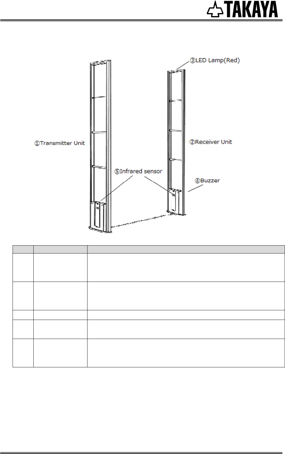
4.1 Names of each part
Names of each partNames of each part
Names of each part
No.
Product Name
Functional Descriptions
①
Transmitter
Unit
TS-A1
-Transmits radio frequencies (8.2MHz) for detecting RF tag.
-Consists of antenna and PCB
-Possible to In/output slave signals required to several pedestals.
②
Receiver Unit
TS-A1
-Receives radio frequencies (8.2MHz) for detecting RF tag.
-Consists of antenna, PCB, LED Lamp and buzzer in this unit.
-Possible to output relay signal when a tag signal is detected.
③
LED Lamp -Lights when a tag signal is detected.
④
Buzzer -Alarms when a tag signal is detected. (possible to integrate with
infrared sensor signal)
⑤
Infrared Sensor
(optional)
-Responds when people get through the aisle between two
pedestals.
Possible to activate an alarm when the sensor is ON
Model Name: TS-A1-FCC
7 / 10
仕様書番号: TDR-MNL-TS-A1-FCC-100
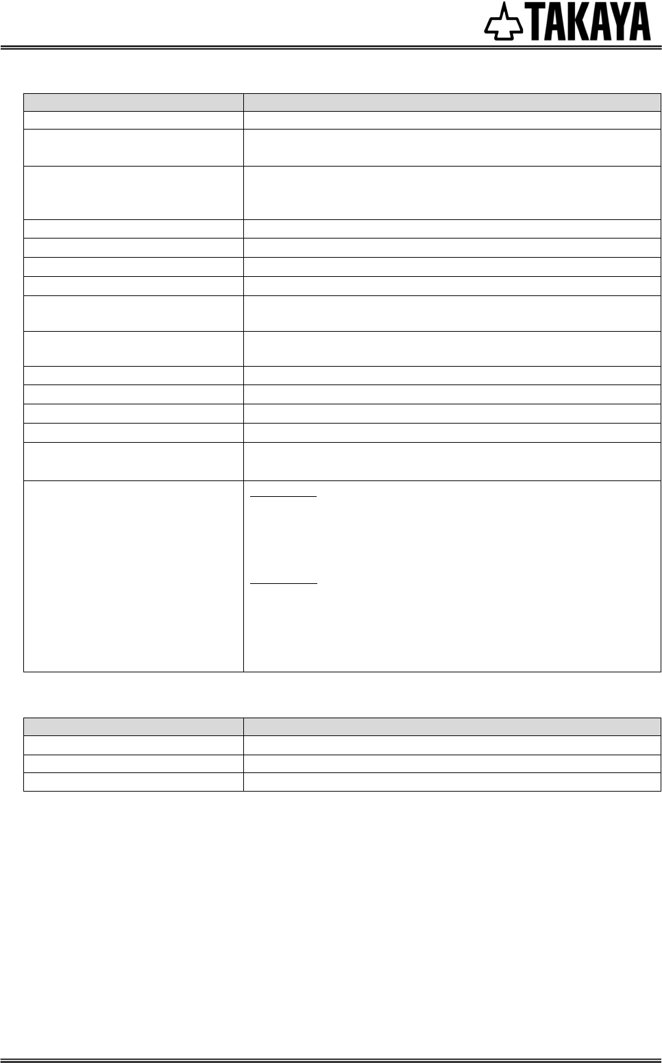
4.2
4.24.2
4.2 Product
ProductProduct
Product
Specifications
SpecificationsSpecifications
Specifications
Item
Descriptions
Detection Frequency
8.2MHz ±500kHz
Sync. frequency
S
ine wave
122.1
Hz(standard)
Possible to change until 116~125Hz in every 3Hz step
Detection range
1200~2,400(mm) / one side
The detection range is changeable depending on a tag used,
tag- frequency and installation situation.
Antenna
2Loop, 3Loop
Operating temperature 10~40(℃)
Operating Humidity 30~85(%RH)(No condensation)
Power(Voltage) DC+16(V)±10(%)
Current Consumption
TS
-
A1
-
TX :
Less than
1.0 (A)
TS-A1-RX : Less than 0.5 (A)
Power Consumption
TS
-
A1
-
TX :
Less than 1
9
.
2
(
W
)
TS-A1-RX : Less than 8 (W)
Dimension of Main parts
326(W)×80(D)×1,670(H)(mm)
Weight 4.9(kg)(without packing materials)
color Silver/Black(Bottom cover)
Material Aluminum、Plastic(Bottom cover)
Packing Box
(1unit per 1pack)
Dimension:40(W)×110(D)×1,730(H)(mm)
Weight:2.0(kg)
Terminals
TS
-
A1
-
TX
Input/output power × 2
Infrared sensor power × 1
Slave Input × 1
Slave Output ×1
TS-A1-RX
Input/output power × 2
Infrared sensor power × 1
Infrared sensor input × 2
Alarm output(buzzer) × 1 (Relay) × 1
Lamp light output × 2
4.3
4.34.3
4.3 Anchor bolts
Anchor boltsAnchor bolts
Anchor bolts
Item
Descriptions
Dimension M8×70(mm)
Maximum tensile load
705
(
kgf
)
Shear loads
1,030
(
kgf
)
Note: When concrete strength 210(kgf/cm
2
) and embedded depth 35(mm)
Model Name: TS-A1-FCC
8 / 10
仕様書番号: TDR-MNL-TS-A1-FCC-100
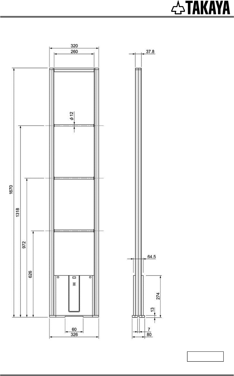
4.4
4.44.4
4.4 Exterior dimension
Exterior dimensionExterior dimension
Exterior dimension
Unit : mm
Model Name: TS-A1-FCC
9 / 10
仕様書番号: TDR-MNL-TS-A1-FCC-100
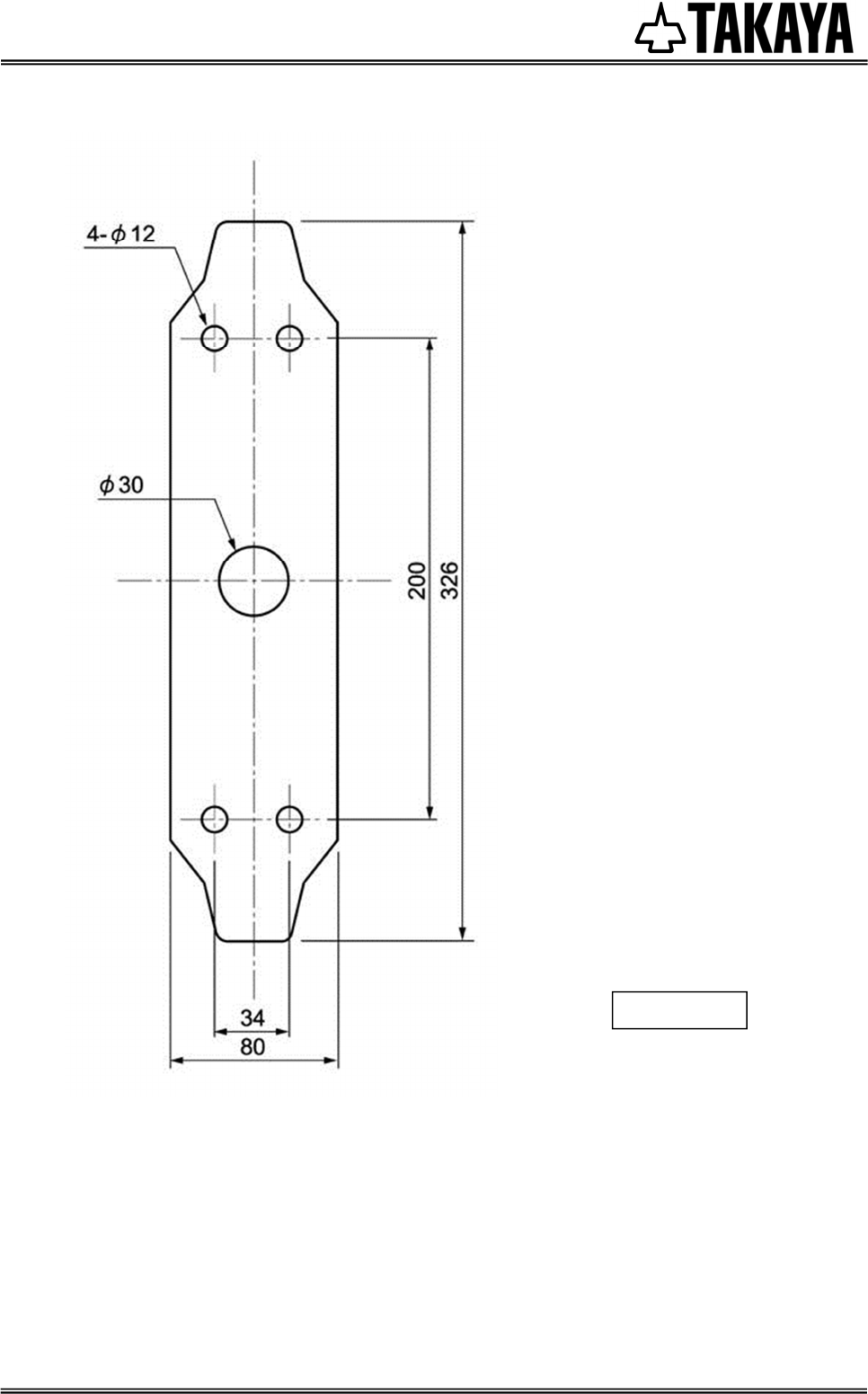
4.5
4.54.5
4.5 Bottom base
Bottom baseBottom base
Bottom base
Unit : mm

Model Name: TS-A1-FCC
10 / 10
仕様書番号: TDR-MNL-TS-A1-FCC-100
5
55
5 Revised h
Revised hRevised h
Revised history
istoryistory
istory
Ver No
Date
Remarks
1.00
2014
/
9
/
5
new
.