TBS Avionics TX2W TBS CROSSFIRE User Manual Users manual
TBS Avionics Limited TBS CROSSFIRE Users manual
UserManual.wiki
>
TBS Avionics
>
TX2W User Manual
>
Users manual
Contents
1.
Users manual
2.
Users manual addendum
Users manual
Navigation menu
Upload a User Manual
Namespaces
Wiki Guide
HTML
PDF
Info
Views
User Manual
Discussion / Help
Navigation
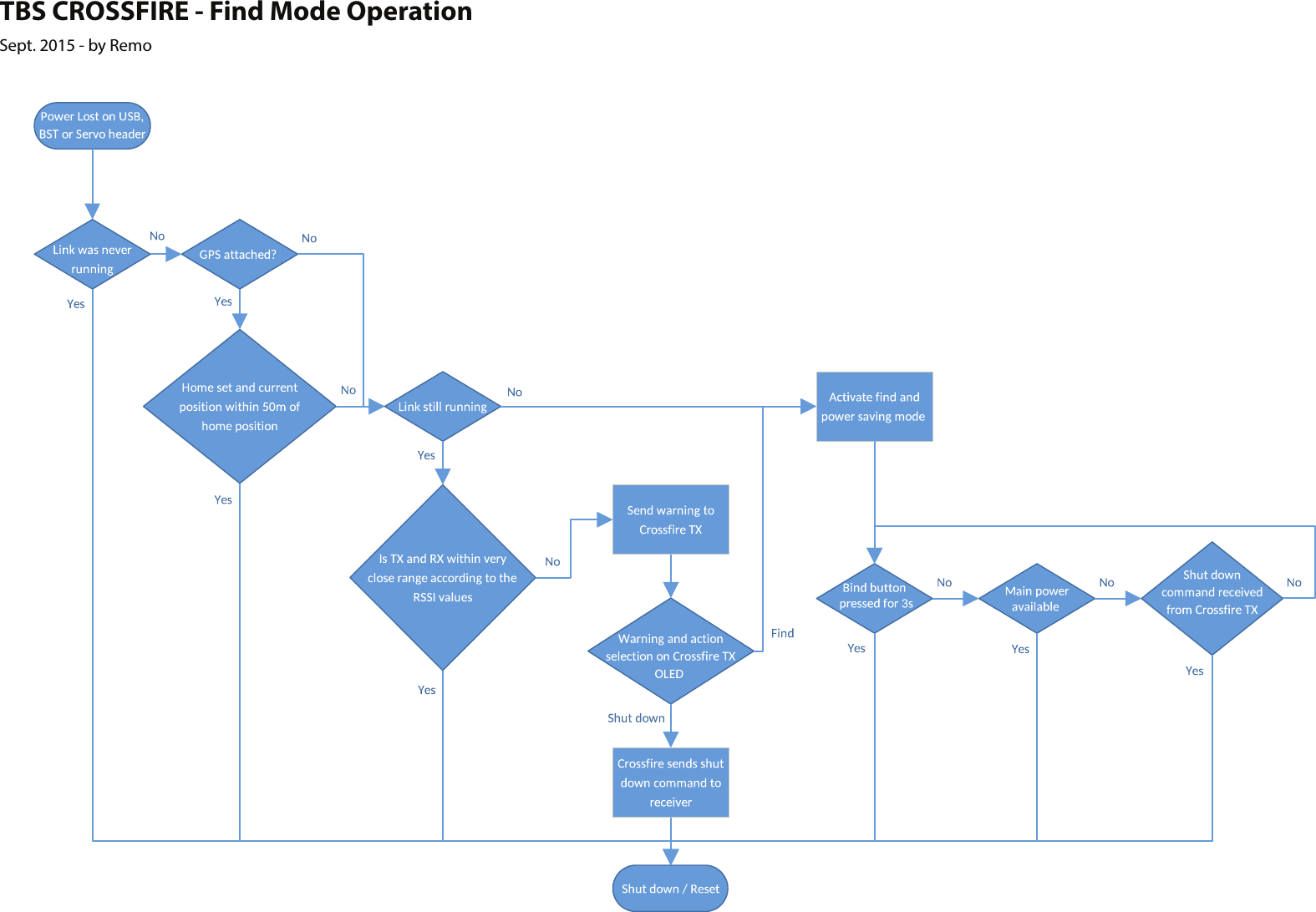
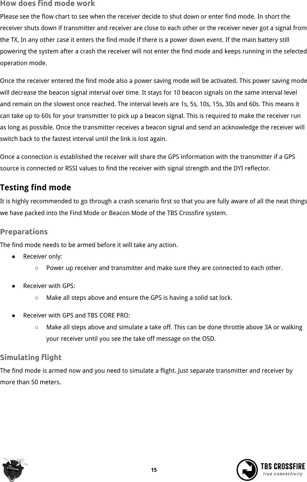
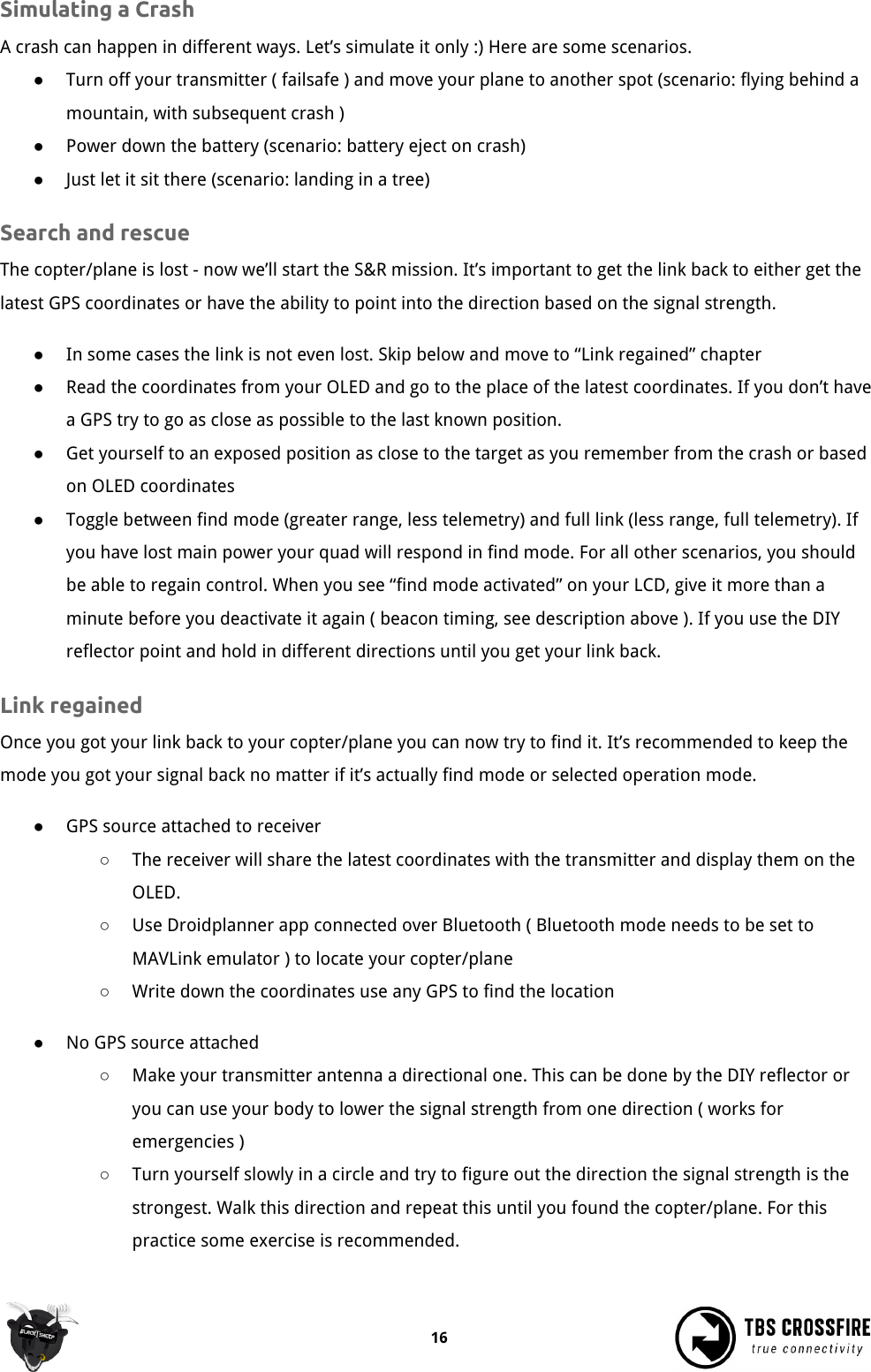
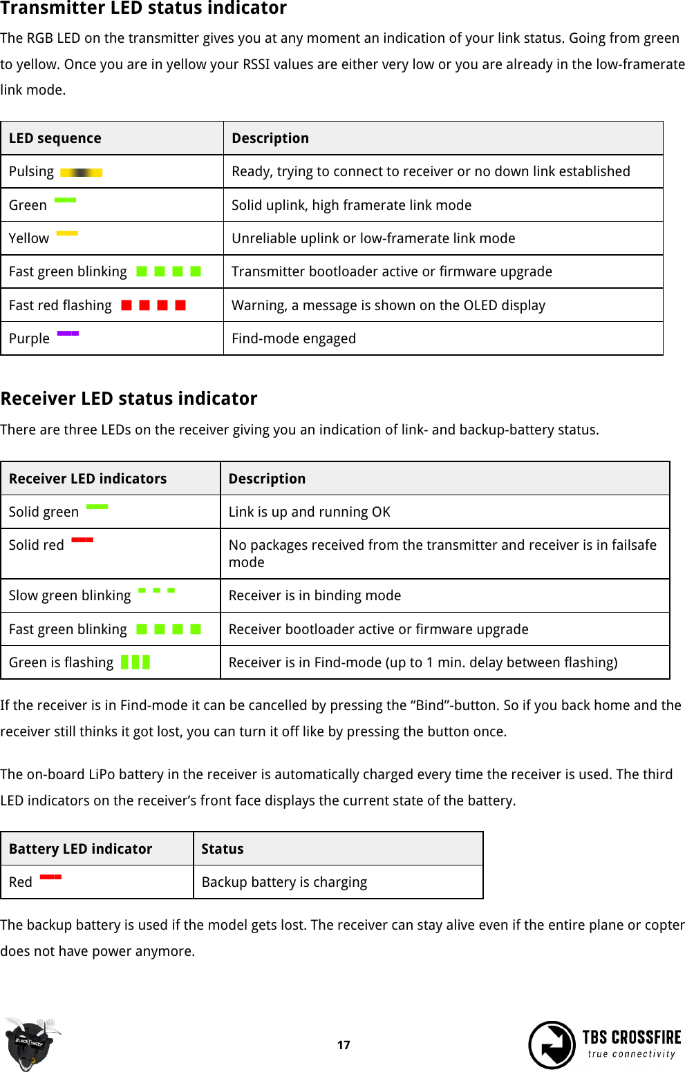
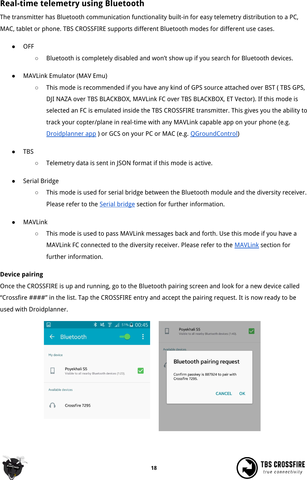
![Operation Status display After power-on, the main screen shows the current state of the transmitter, i.e. link status, transmission power, R/C- and head-tracking input signal state. ●Link Status - State of the wireless link [Connecting, Running] ●TX Power - Output transmission power [10mW, 25mW, 100mW, 500mW, 1W, 2W] ●RC Input - Radio R/C PPM signal input status [No signal, Signal OK] ●HT Input - Head-tracking PPM signal input status[No signal, Signal OK] Up- and downlink status Toggle the joystick to the right to show the status of the up- and downlink. ●RSSI - Received signal strength indicator, measurement of the power present in a received radio signal [typ. -1dBm (good) to -130dBm (bad), logarithmic scale] ●LQ - Link Quality, based on the percentage of signal data received at the end-point [0 to 300%] ●SNR - Signal-to-noise ratio, compares the level of a desired signal to the level of background noise The RSSI determines your available link budget on a logarithmic scale, with each additional -6dBm representing twice the range of your current distance. E.g. you are at 5km range with a RSSI of -84dBm. At a range of 10km you are expected to see a -90dBm RSSI. The receiver is capable of receiving signals up to -130dBm. The SNR plots your current RSSI against the noise floor, giving you a rough indication of the remaining range in real-time. The CROSSFIRE can receive signals down to about -12dB SNR, way below the noise floor. Any SNR above 8dB cannot be accurately measured and will result in an SNR of 8dBm. 13](https://usermanual.wiki/TBS-Avionics/TX2W.Users-manual/User-Guide-3189982-Page-13.png)
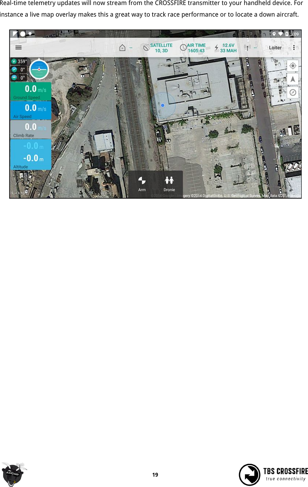
![CROSSFIRE runs different RF Profiles at time. For a better understanding which RF profile is active we assume 50Hz update rate as 100%. This will give you up to 300% LQ for operation mode normal and up to 100% LQfor force telemetry. Any LQ above 80% is fine. LQ at 50% you can still comfortably fly a gimbal-quad in ATTIor GPS mode since there is still a certain amount of valid data reaching the flight controller. Find mode The Find-mode provides you with a way to locate a downed aircraft. A GPS signal is currently required to use this mode (other detection modes are being developed). Install our TBS GPS module or TBS BLACKBOX logging unit (via APM/NAZA GPS) to the BST-port on side of the receiver. In normal use the GPS coordinates are continuously updated and the latest data is displayed on the “Find Mode” screen. If the model looses power you can review the last known coordinates to locate your model. ●Inactive (Press Enter) / Active - Enable/disable the Find-mode, shows on-board LiPo voltage Do NOT enable during flight! ●Signal - Receiver signal strength, makes it possible to triangulate the location [0 to 100%] ●Alt - Altitude above Sea Level, GPS required [0 to 5000m] ●Lat - Latitude, GPS required ●Lat - Longitude, GPS required The receiver has an on-board LiPo battery to operate in beacon-mode. This allows the transmitter to send the last known GPS coordinates to the display on the transmitter, after certain trigger events have happened. See the operation flow diagram on the following page. Direction finder Using the transmitter antenna together with a parabolic reflector, you can estimate the heading of the receiver by looking at the signal strength indicator. Print out the DIY reflector template included on the last pages of this manual with no scaling on thick paper, place a of aluminium foil on top of the main reflector sheet and cut out the shapes with an exacto knife. Place the reflector in the middle of the antenna. 14](https://usermanual.wiki/TBS-Avionics/TX2W.Users-manual/User-Guide-3189982-Page-15.png)