TBS Avionics VIDEOTX Video Transmitter User Manual
TBS Avionics Limited Video Transmitter Users Manual
Users Manual

TBS GREENHORN 5.8GHz
25mW Video Transmitter
Introduction
The TBS GREENHORN 5.8GHz 25mW video transmitter is aimed at
the beginner FPV pilot. It’s a license-free, CE & FCC certified,
medium range video transmitter with solid video signal for up to
500m (1/2 mile) on stock antennas. Directional video receiver
antennas increase range and are available from various sources.
It operates off a 5V powersource and is compatible with all
Lawmate transmitter module pinout. This allows you to switch the
transmitter according to your planned flight requirement and
flying distance.
For optimal operation we suggest to use this transmitter together with the TBS CORE. The TBS CORE
comes with cables that allow plug & play installation.
Installation
Installation of the transmitter is easy. It comes with a pigtail connector that you can use to make your
own cables. The pinout of the cable is according to following color scheme:
Yellow = Video
White = Audio
Black = GND
Red = 5V+

The pins of the connector are also labelled on the front of the video transmitter. Please verify the pinout
of the plug and that everything is wired correctly before powering up your video transmitter for the first
time!
Attach the supplied 4-leaf Cloverleaf antenna with care. Do not bend or modify the top (receiving part)
of the antennas! When travelling with your plane please use the provided transport case for the
antennas to avoid damaging your antenna and reducing its range.
Channel Selection
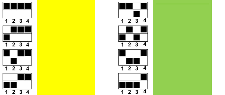
The TBS Greenhorn supports 8 channels in the 5.8GHz ISM Band. The channels are selected using the
dipswitch located at the back of the video transmitter.
The channels of the TBS 5.8 GHz video system are color-coded. The antennas you purchased are
optimized for a certain range of channels. These channels are grouped using various colors. The CL/SPW
antennas are marked with a little piece of colored shrink-tube at the base of the antenna. The
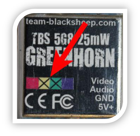
transmitter’s capable frequencies are printed on the label and marked with an „X“. Find a channel
matching both your transmitter’s frequency and antenna frequency and set it with the dipswitch. The
supported channels, also color coded, are listed in the table below.

Channel 1
(5735 MHz)
Channel 5
(5805 MHz)
Channel 2
(5745 MHz)
Channel 6
(5825 MHz)
Channel 3
(5765 MHz)
Channel 7
(5845 MHz)
Channel 4
(5785 MHz)
Channel 8
(5865 MHz)
Antenna Positions
Place your antenna as far away from electronic and metal components as possible. Any metallic surface
will reflect radio waves and reduce your range. Position the video transmitter flat, so that the antenna is
pointing vertical up or down. The antenna must be protected from crash damage. If the antenna is bent
the video link will no longer work at the exceptional ranges as before.
Changes or modifications not expressly approved by the party responsible for compliance could void the
user's authority to operate the equipment.
This device complies with part 15 of the FCC rules. Operation is subject to the following two conditions
(1) this device may not cause harmful interference, and
(2) this device must accept any interference received, including interference that may cause undesired operation.