TECHVIEW R150S Router inalambrico N150 User Manual Part Two
TECHVIEW,INC Router inalambrico N150 Users Manual Part Two
UserManual.wiki
>
TECHVIEW
>
R150S User Manual
>
Users Manual Part Two
Contents
1.
Users Manual Part One
2.
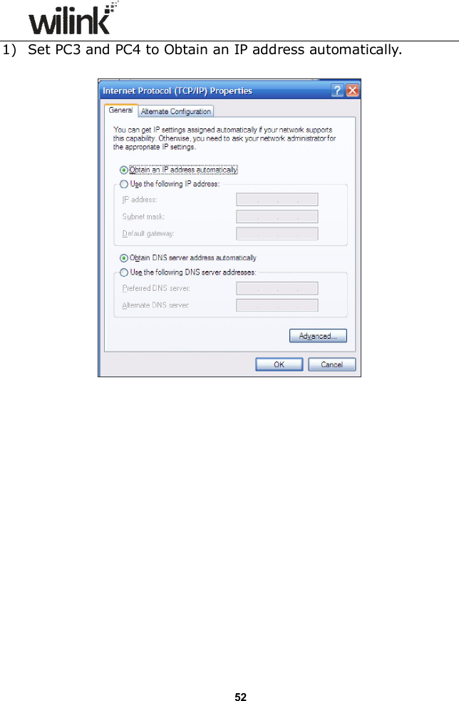
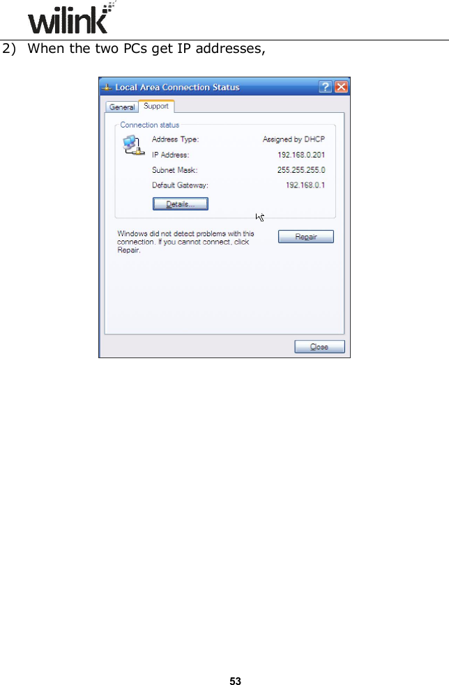
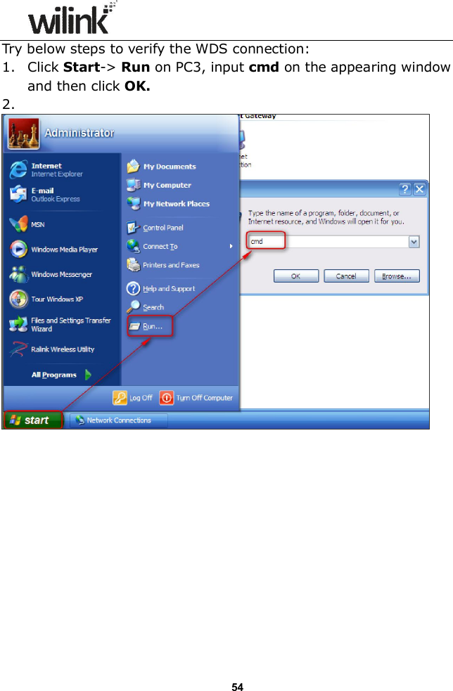
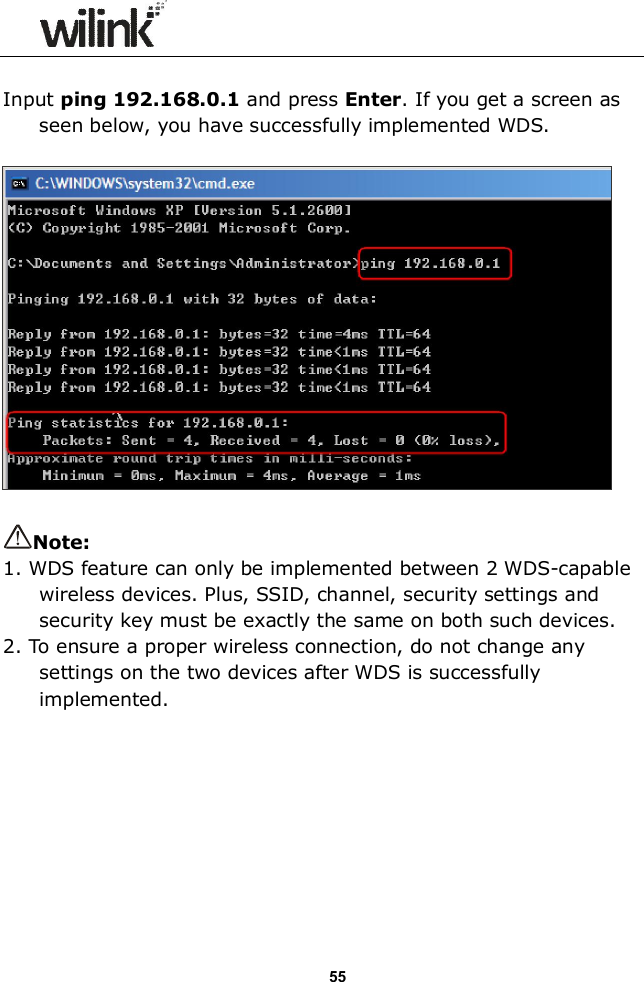
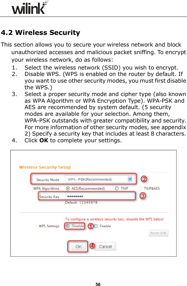
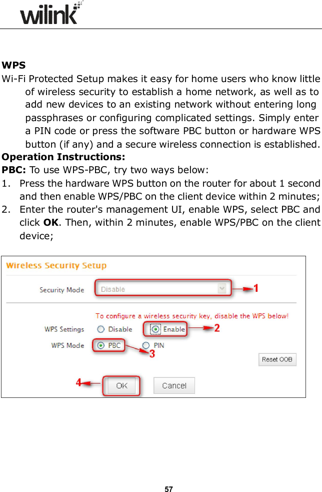
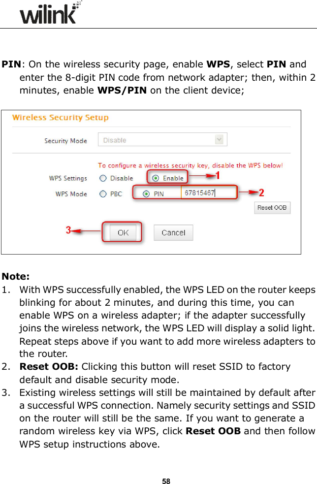
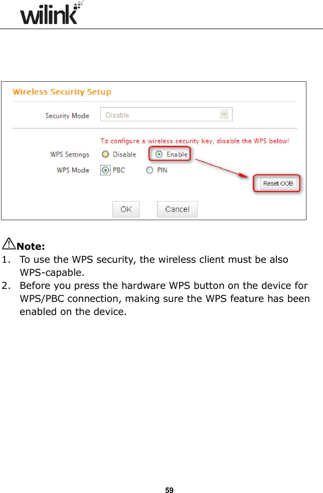
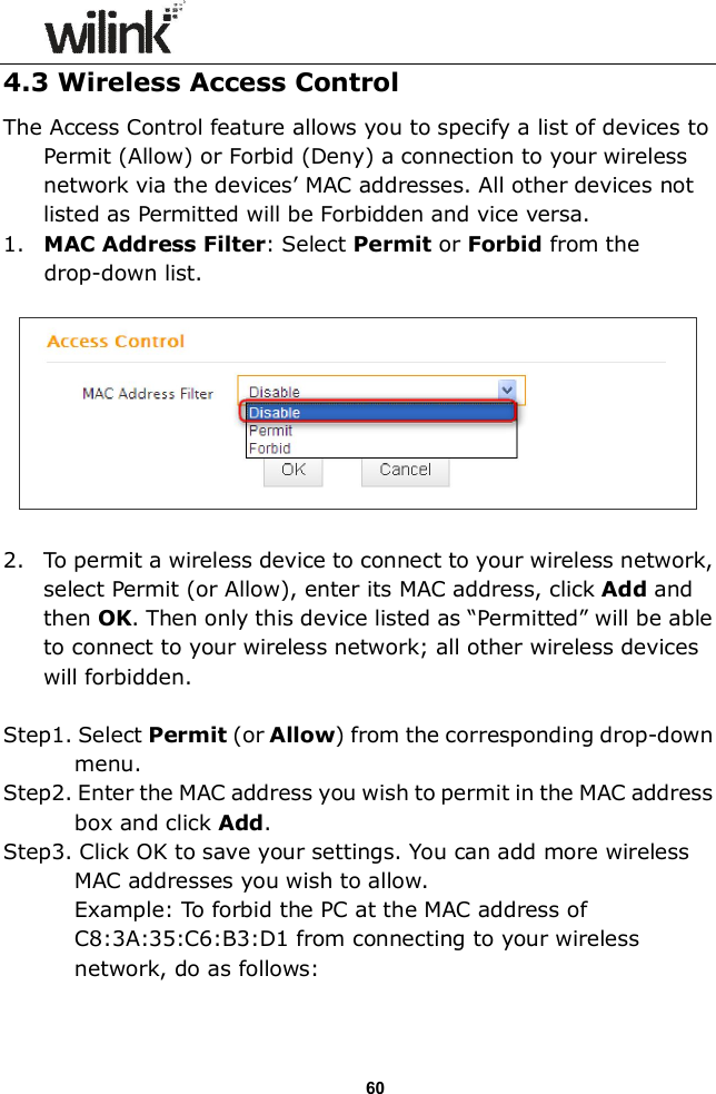
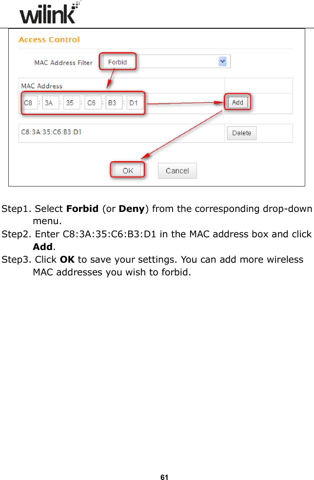
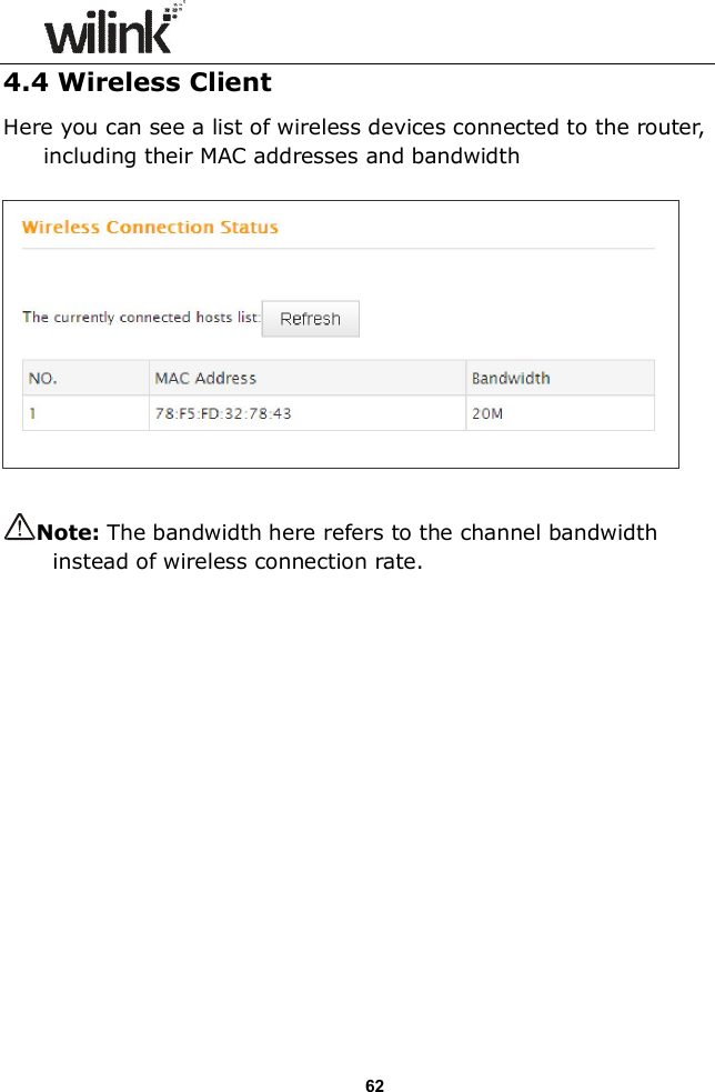
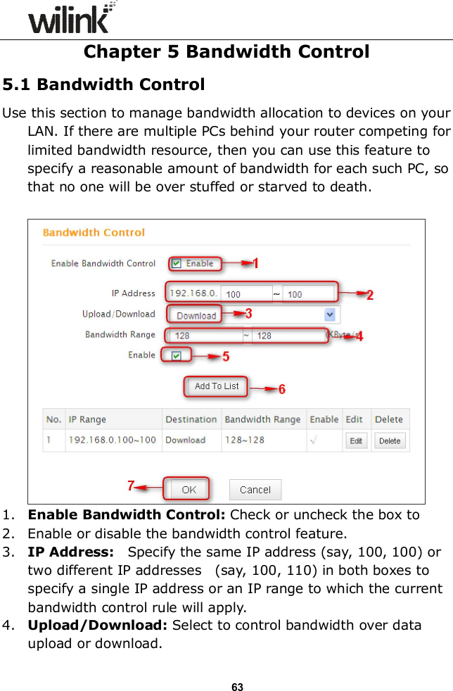
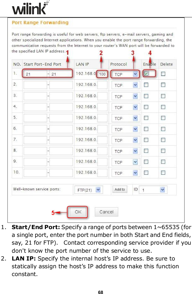
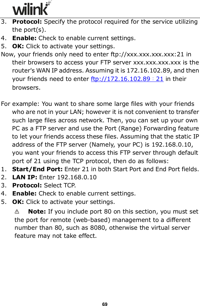
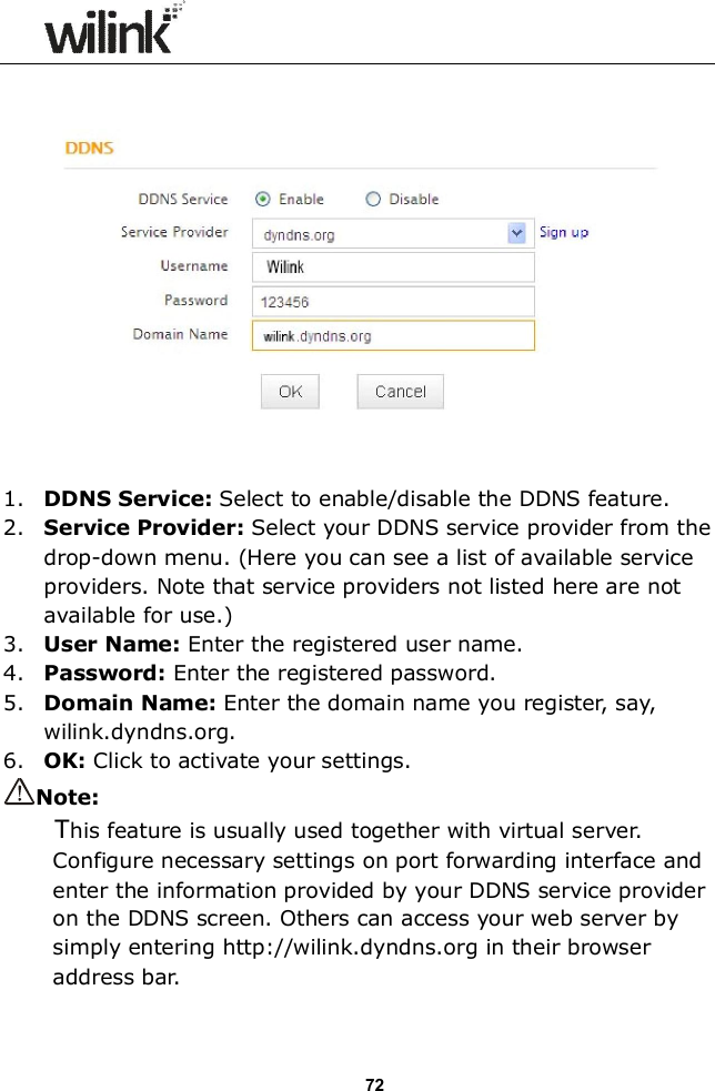
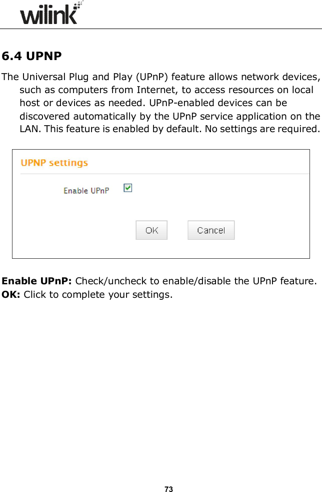
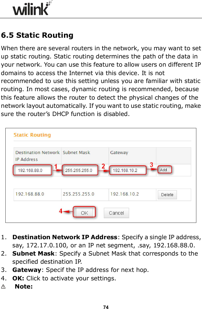
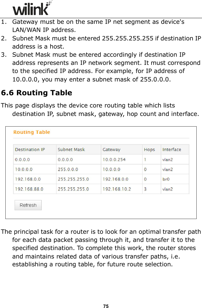
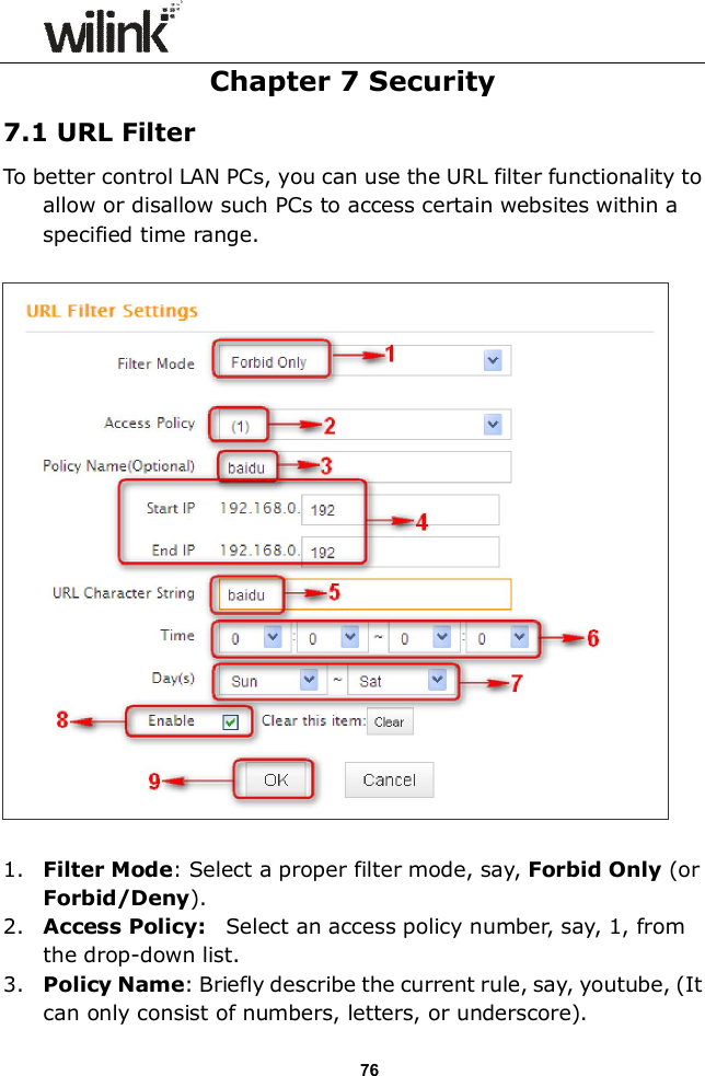
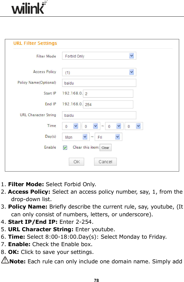
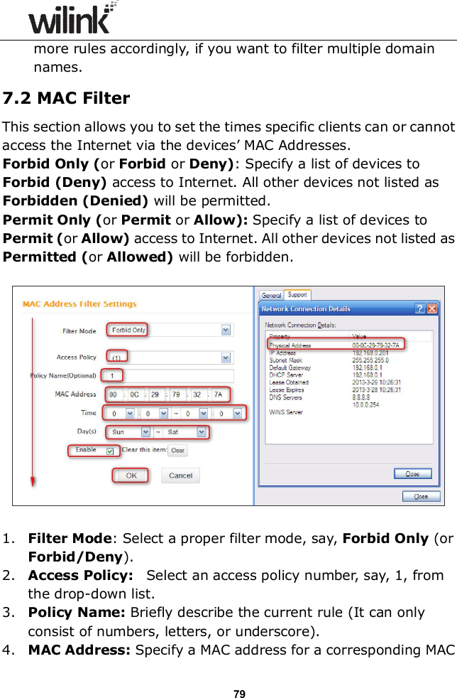
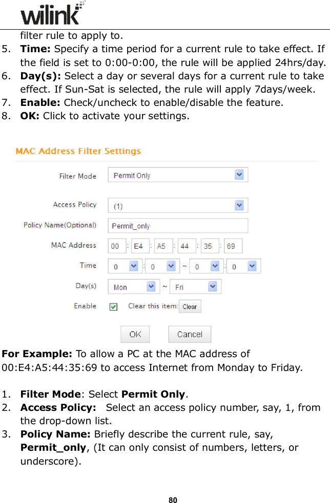
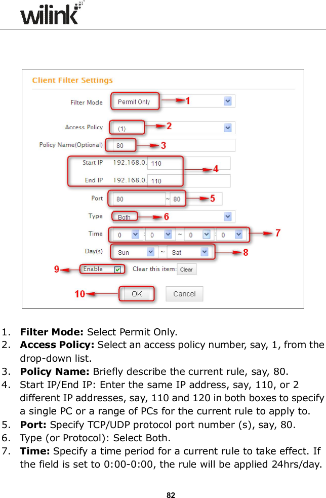
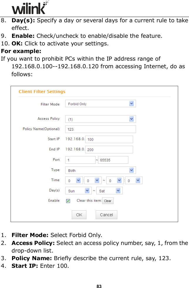
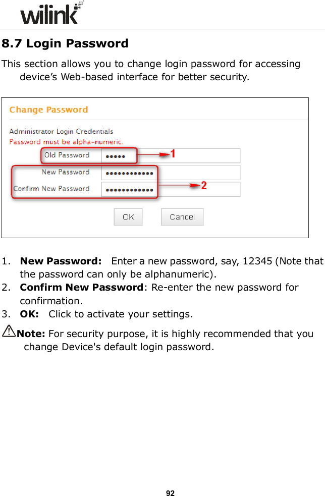
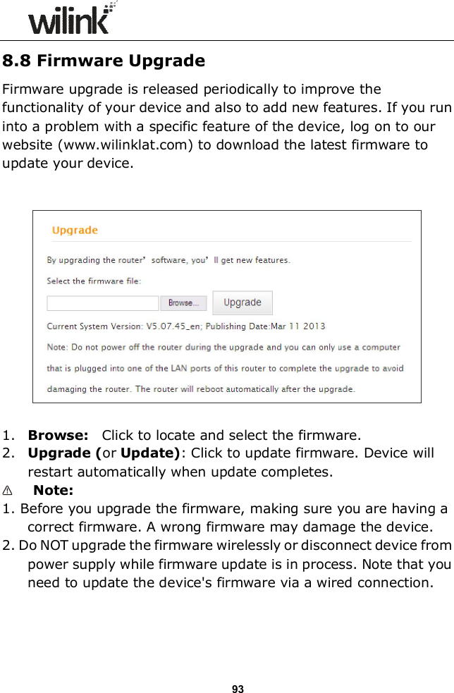
Users Manual Part Two
Users Manual Part Two
Navigation menu
Upload a User Manual
Namespaces
Wiki Guide
HTML
PDF
Info
Views
User Manual
Discussion / Help
Navigation