TECHVIEW R300T Router inalambrico N300 User Manual Part Two
TECHVIEW,INC Router inalambrico N300 Users Manual Part Two
TECHVIEW >
Contents
- 1. Users Manual Part One
- 2. Users Manual Part Two
Users Manual Part Two
37
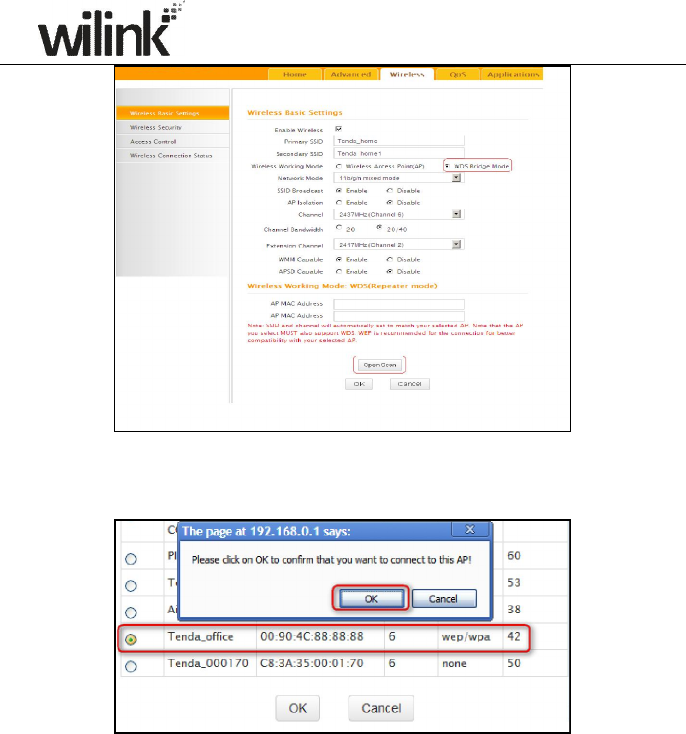
3) Select the wireless network to connect and click OK.
4) Verify that the SSID, channel, and AP MAC address on the page match
those of the added wireless network. If not, manually correct them.
38
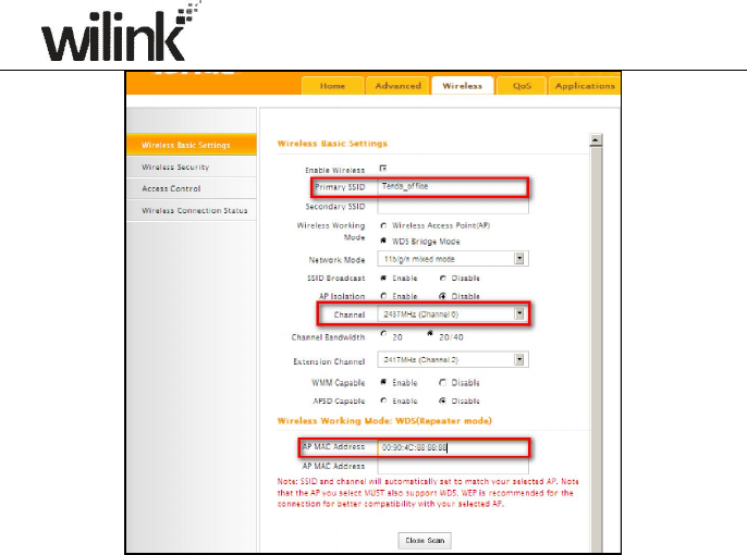
5) Close Scan and click OK to save your settings.
39
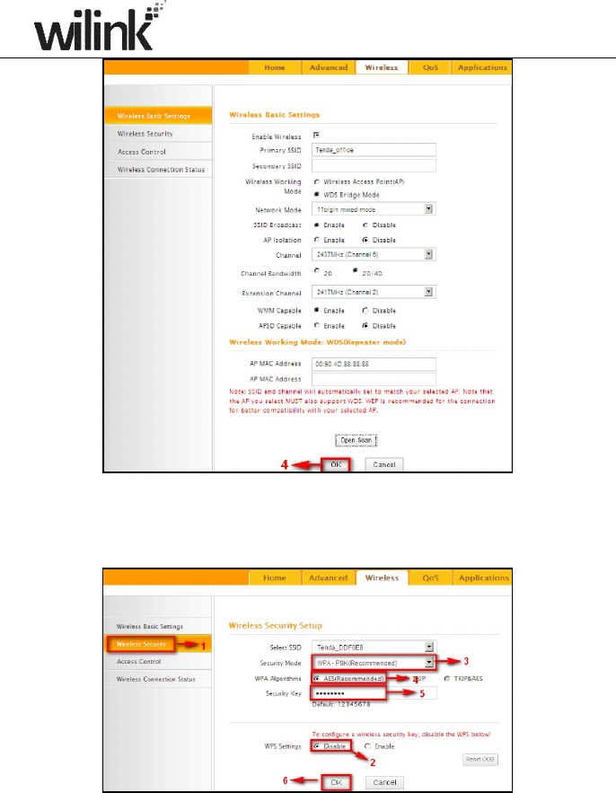
6) Go to Wireless Security page and set the wireless security settings exactly as they
are on the link partner (Router 1).
7) Go to DHCP Server to disable the DHCP on Router 2. Now you have finished all
settings on Router 2 required for WDS.
40
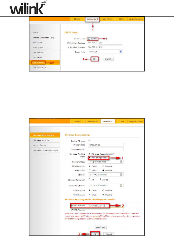
2. Configure Router 1:
1) Go to wireless section on Router 1 and specify WDS (or WDS Bridge)
as its wireless working mode.
2) Manually enter Router 2's MAC address (Also, you can use the Scan
option as mentioned above) and click OK to finish your settings.
3. Configure PC3 and PC4:
41
1) Set PC3 and PC4 to Obtain an IP address automatically.
2) When the two PCs get IP addresses,
42
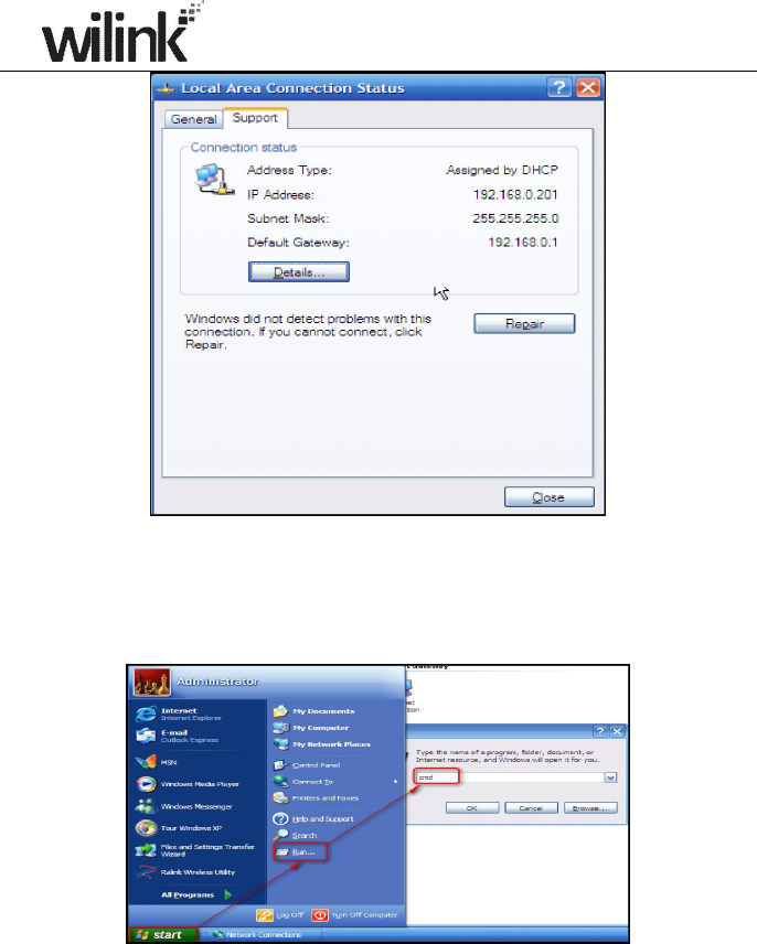
try below steps to verify the WDS connection:
Click Start-> Run on PC3, input cmd on the appearing window and then
click OK.
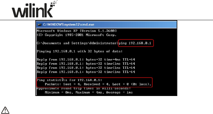
Input ping 192.168.0.1 and press Enter. If you get a screen as seen below,
you have successfully implemented WDS.
43
Note:
1. WDS feature can only be implemented between 2 WDS-capable wireless
devices. Plus, SSID, channel, security settings and security key must be
exactly the same on both such devices.
2. To ensure a proper wireless connection, do not change any settings on
the two devices after WDS is successfully implemented.
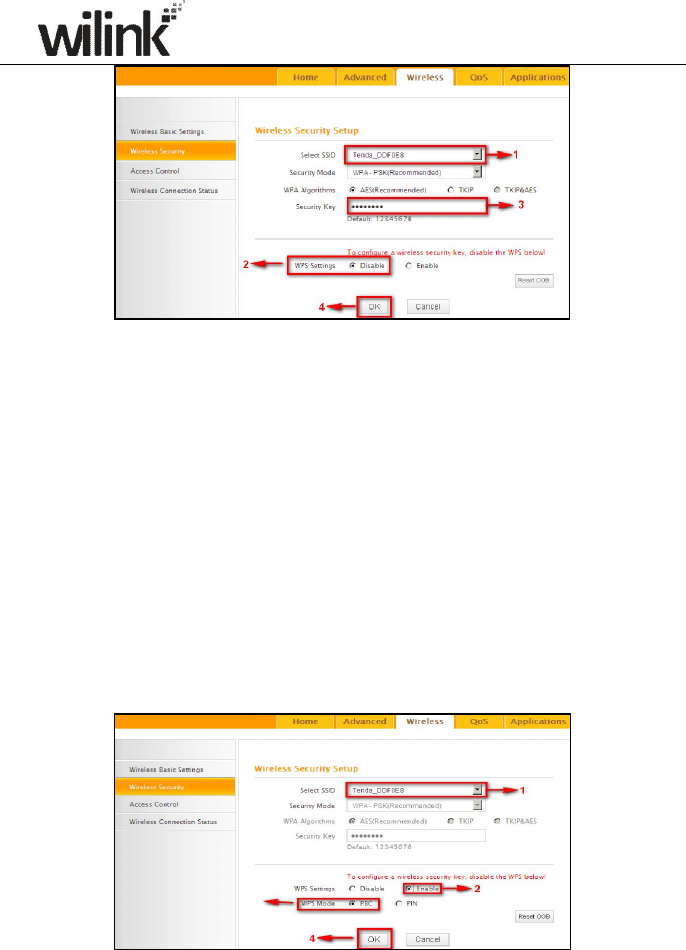
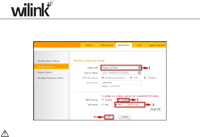
4.2 Wireless Security
This section allows you to secure your wireless network and block
unauthorized accesses and malicious packet sniffing. To encrypt your
wireless network, do as follows:
1. Select the wireless network (SSID) you wish to encrypt.
2. Disable WPS. (WPS is enabled on the router by default. If you want to
use other security modes, you must first disable the WPS.)
3. Select a proper security mode and cipher type (also known as WPA
Algorithm or WPA Encryption Type). WPA-PSK and AES are
recommended by system default. (5 security modes are available for
your selection. Among them, WPA-PSK outstands with greater
compatibility and security. For more information of other security modes,
see appendix 2) Specify a security key that includes at least 8
characters.
4. Click OK to complete your settings.
44
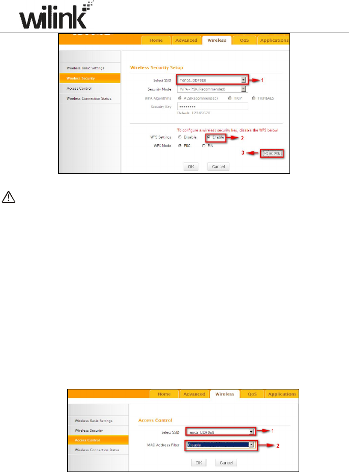
WPS
Wi-Fi Protected Setup makes it easy for home users who know little of
wireless security to establish a home network, as well as to add new devices
to an existing network without entering long passphrases or configuring
complicated settings. Simply enter a PIN code or press the software PBC
button or hardware WPS button (if any) and a secure wireless connection is
established.
Operation Instructions:
PBC: To use WPS-PBC, try two ways below:
1) Press the hardware WPS button on the router for about 1 second and
then enable WPS/PBC on the client device within 2 minutes;
2) Press the hardware WPS button on the router for about 1 second and
then enable WPS/PBC on the client device within 2 minutes;
PIN: On the wireless security page, enable WPS, select PIN and enter the
45
8-digit PIN code from network adapter; then, within 2 minutes, enable
WPS/PIN on the client device;
Note:
1. With WPS successfully enabled, the WPS LED on the router keeps
blinking for about 2 minutes, and during this time, you can enable WPS
on a wireless adapter; if the adapter successfully joins the wireless
network, the WPS LED will display a solid light. Repeat steps above if you
want to add more wireless adapters to the router.
2. Reset OOB: Clicking this button will reset SSID to factory default and
disable security mode.
3. Existing wireless settings will still be maintained by default after a
successful WPS connection. Namely security settings and SSID on the
router will still be the same. If you want to generate a random wireless
key via WPS, click Reset OOB and then follow WPS setup instructions
above.
46
Note:
1. To use the WPS security, the wireless client must be also WPS-capable.
2. Before you press the hardware WPS button on the device for WPS/PBC
connection, making sure the WPS feature has been enabled on the
device.
4.3 Wireless Access Control
The Access Control feature allows you to specify a list of devices to Permit or
Forbid a connection to your wireless network via the devices’ MAC addresses.
All other devices not listed as Permitted will be Forbidden and vice versa.
1. Select the wireless network (SSID) you wish to enable Access Control
on.
2. MAC Address Filter: Select Permit or Forbid from the drop-down list.
3. To permit a wireless device to connect to your wireless network, select
Permit (or Allow), enter its MAC address, click Add and then OK. Then
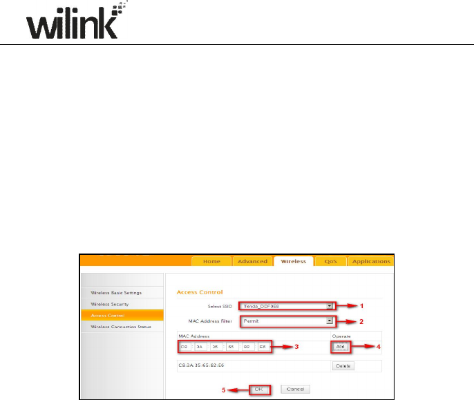
47
only this device listed as “Permitted” will be able to connect to your
wireless network; all other wireless devices will forbidden.
Step1. Select the wireless network (SSID) you wish to enable Access Control
on.
Step2. Select Permit from the corresponding drop-down menu.
Step3. Enter the MAC address you wish to permit in the MAC address box
and click Add.
Step4. Click OK to save your settings. You can add more wireless MAC
addresses you wish to allow.
Example: To forbid the PC at the MAC address of C8:3A:35:65:82:E6 from
connecting to your wireless network, do as follows:
Step1. Select an SSID, say, Wilink_home.
Step2. Select Forbid (or Deny) from the corresponding drop-down menu.
Step3. Enter C8:3A:35:65:82:E6 in the MAC address box and click Add.
Step4. Click OK to save your settings. You can add more wireless MAC
addresses you wish to forbid.
4.4 Wireless Client
Here you can see a list of wireless devices connected to the router, including
their MAC addresses and bandwidth
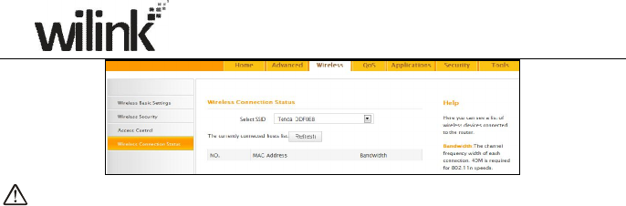
48
Note: The bandwidth here refers to the channel bandwidth instead of
wireless connection rate.
49
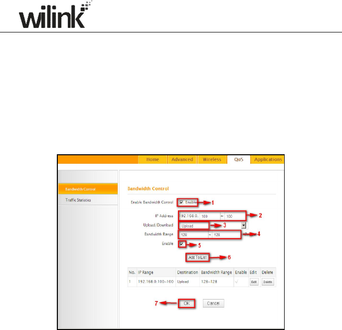
Chapter 5 Bandwidth Control
5.1 Bandwidth Control
Use this section to manage bandwidth allocation to devices on your LAN. If
there are multiple PCs behind your router competing for limited bandwidth
resource, then you can use this feature to specify a reasonable amount of
bandwidth for each such PC, so that no one will be over stuffed or starved to
death.
1. Enable Bandwidth Control: Check or uncheck the box to
2. Enable or disable the bandwidth control feature.
3. IP Address: Specify the same IP address (say, 100, 100) or two
different IP addresses (say, 100, 110) in both boxes to specify a single
IP address or an IP range to which the current bandwidth control rule will
apply.
4. Upload/Download: Select to control bandwidth over data upload or
download.
5. Bandwidth Range: Specify an upload/download bandwidth range
limit on specified PC(s). The unit is KByte/s. 1M=128KByte/s. Note that
maximum upload/download bandwidth should not exceed your router's
WAN bandwidth limit. (Consult your ISP if you are not clear.).
50
6. Enable: Check to enable current rule. (When disabled, corresponding
entry will not take effect though existing in fact.)
7. Add to List: Click to add current rule to the rule list.
8. OK: Click to activate your settings.
For example:
If you are sharing a 4M broadband connection with a neighbor, who always
exhausts the bandwidth resource downloading data, this feature will help.
Simply specify half of the 4M bandwidth for your neighbor's PC (say,
192.168.0.100) and you will no longer need to struggle for bandwidth and
your neighbor will only get up to 2M bandwidth. To do so, follow instructions
below:
1
1.
. C
Ch
he
ec
ck
k
E
En
na
ab
bl
le
e.
.
2
2. Input "192.168.0.100" in both IP address boxes.
3
3.
.
Select Download.
4
4.
.
Enter "256" in both bandwidth range fields.
5
5.
.
Check Enable.
6
6.
.
Click Add To List
7
7.
.
Click OK.
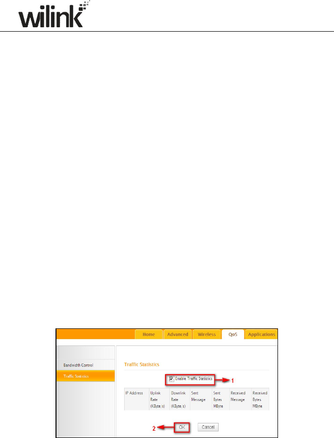
5.2 Traffic Statistics
Traffic Statistics allows you to see at a glance how much traffic each device
in your network is using.
Enable Traffic Statistics: Check/uncheck the box to enable/disable the
Traffic Statistics feature. To see at a glance how much traffic each device in
your network is using, enable this option. However usually, disabling it may
boost your network performance. This option is disabled by default. However,

51
once enabled the page refreshes every five minutes.
OK: Click to activate corresponding settings.
IP Address: Displays IP addresses of PCs connected to the device.
Uplink Rate: Displays the upload speed (KByte/s) of a corresponding PC.
Downlink Rate: Displays the download speed (KByte/s) of a corresponding
PC.
Sent Message: Displays the number of packets sent by a corresponding PC
via the device since Statistics is enabled.
Sent Bytes: Displays the number of Bytes sent by a corresponding PC via
the device since Statistics is enabled. The unit is MByte.
Received Message: Displays the number of packets received by a
corresponding PC via the device since Statistics is enabled.
Received Bytes: Displays the number of Bytes received by a corresponding
PC via the device since Statistics is enabled. The unit is MByte.
52
Chapter 6 Special Applications
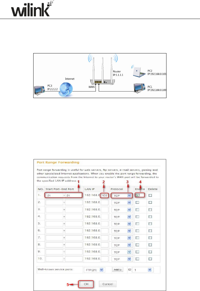
6.1 Port Range Forwarding
Port range forwarding is useful for web servers, ftp servers, e-mail servers,
gaming and other specialized Internet applications. When you enable port
forwarding, the communication requests from the Internet to your router’s
WAN port will be forwarded to the specified LAN IP address. As seen in the
figure above, to let PC3 access service ports on PC1, you must first configure
port forwarding settings on the router to which PC1 is uplinked.

53
1. Start/End Port: Specify a range of ports between 1~65535 (for a
single port, enter the port number in both Start and End fields, say, 21
for FTP). Contact corresponding service provider if you don't know the
port number of the service to use.
2. LAN IP: Specify the internal host’s IP address. Be sure to statically
assign the host’s IP address to make this function constant.
3. Protocol: Specify the protocol required for the service utilizing the
port(s).
4. Enable: Check to enable current settings.
5. OK: Click to activate your settings.
Now, your friends only need to enter ftp://xxx.xxx.xxx.xxx:21 in their
browsers to access your FTP server xxx.xxx.xxx.xxx is the router's WAN IP
address. Assuming it is 172.16.102.89, and then your friends need to enter
ftp://172.16.102.89:21 in their browsers.
For example:
You want to share some large files with your friends who are not in your LAN;
however it is not convenient to transfer such large files across network. Then,
you can set up your own PC as a FTP server and use the Port (Range)
Forwarding feature to let your friends access these files. Assuming that the
static IP address of the FTP server (Namely, your PC) is 192.168.0.10, you
want your friends to access this FTP server through default port of 21 using
the TCP protocol, then do as follows:
1. Start/End Port: Enter 21 in both Start Port and End Port fields.
2. LAN IP: Enter 192.168.0.10
3. Protocol: Select TCP.
4. Enable: Check to enable current settings.
5. OK: Click to activate your settings.
Note: If you include port 80 on this section, you must set the port for
remote (web-based) management to a different number than 80, such
as 8080, otherwise the virtual server feature may not take effect.
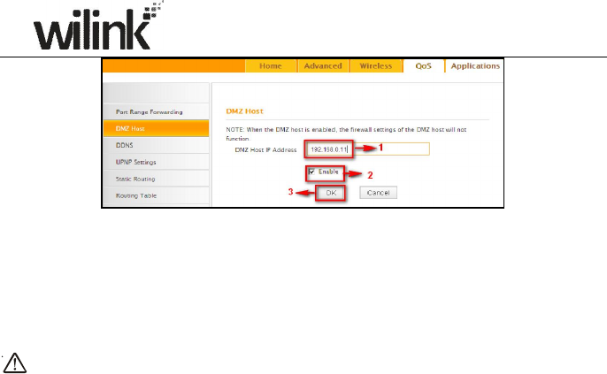
6.2 DMZ Host
The DMZ (De-Militarized Zone) function disables the firewall on the router
for one device for a special purpose service such as Internet gaming or video
conferencing. Enabling DMZ host may expose your local network to potential
attacks. So it is advisable to use it with caution.
54
1. DMZ Host IP Address: The IP Address of the device for which the
router’s firewall will be disabled. Be sure to statically set the IP Address
of that device for this function to be consistent.
2. Enable: Check/uncheck to enable/disable the DMZ host feature.
3. OK: Click to enable your settings.
Note:
Once enabled, the DMZ host loses protection from device's firewall and
becomes vulnerable to attacks.
6.3 DDNS
Dynamic DNS or DDNS is a term used for the updating in real time of
Internet Domain Name System (DNS) name servers. Dynamic DNS or DDNS
is a term used for the updating in real time of Internet Domain Name System
(DNS) name servers. We use a numeric IP address allocated by Internet
Service Provider (ISP) to connect to Internet; the address may either be
stable ("static"), or may change from one session on the Internet to the next
("dynamic"). However, a numeric address is inconvenient to remember; an
address which changes unpredictably makes connection impossible. The
DDNS provider allocates a static host name to the user; whenever the user
is allocated a new IP address this is communicated to the DDNS provider by
software running on a computer or network device at that address; the
provider distributes the association between the host name and the address
to the Internet's DNS servers so that they may resolve DNS queries. Thus,
uninterrupted access to devices and services whose numeric IP address may
change is maintained. (You need to have an account with one of the Service
Providers in the drop-down menu first.)

55
1. DDNS Service: Select to enable/disable the DDNS feature.
2. Service Provider: Select your DDNS service provider from the
drop-down menu. (Here you can see a list of available service providers.
Note that service providers not listed here are not available for use.)
3. User Name: Enter the registered user name.
4. Password: Enter the registered password.
5. Domain Name: Enter the domain name you register, say,
Wilink.dyndns.org.
6. OK: Click to activate your settings.
Note:
This feature is usually used together with virtual server. Configure necessary
settings on port forwarding interface and enter the information provided by
your DDNS service provider on the DDNS screen. Others can access your
web server by simply entering http://wilink.dyndns.org in their browser
address bar.
6.4 UPNP
The Universal Plug and Play (UPnP) feature allows network devices, such as
computers from Internet, to access resources on local host or devices as
needed. UPnP-enabled devices can be discovered automatically by the UPnP
service application on the LAN. This feature is enabled by default. No
settings are required.
Enable UPnP: Check/uncheck to enable/disable the UPnP feature.
56
OK: Click to complete your settings.
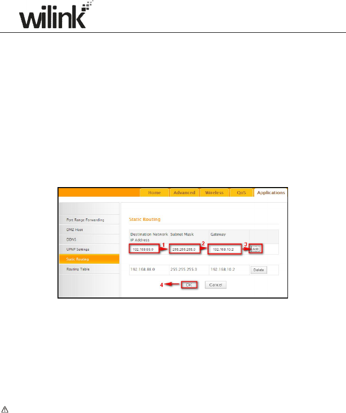
6.5 Static Routing
When there are several routers in the network, you may want to set up static
routing. Static routing determines the path of the data in your network. You
can use this feature to allow users on different IP domains to access the
Internet via this device. It is not recommended to use this setting unless you
are familiar with static routing. In most cases, dynamic routing is
recommended, because this feature allows the router to detect the physical
changes of the network layout automatically. If you want to use static
routing, make sure the router’s DHCP function is disabled.
1. Destination Network IP Address: Specify a single IP address, say,
172.17.0.100, or an IP net segment, .say, 192.168.88.0.
2. Subnet Mask: Specify a Subnet Mask that corresponds to the specified
destination IP.
3. Gateway: Specify the IP address for next hop.
4. OK: Click to activate your settings.
Note:
1. Gateway must be on the same IP net segment as device's LAN/WAN IP
address.
2. Subnet Mask must be entered 255.255.255.255 if destination IP address
is a host.
3. Subnet Mask must be entered accordingly if destination IP address
represents an IP network segment. It must correspond to the specified
IP address. For example, for IP address of 10.0.0.0, you may enter a
57
subnet mask of 255.0.0.0.
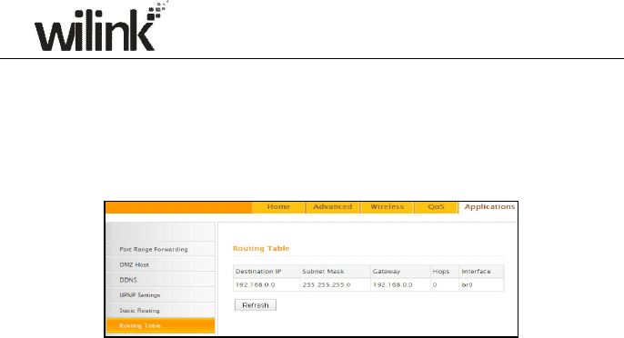
6.6 Routing Table
This page displays the device core routing table which lists destination IP,
subnet mask, gateway, hop count and interface.
The principal task for a router is to look for an optimal transfer path for each
data packet passing through it, and transfer it to the specified destination.
To complete this work, the router stores and maintains related data of
various transfer paths, i.e. establishing a routing table, for future route
selection.
58
Chapter 7 Security
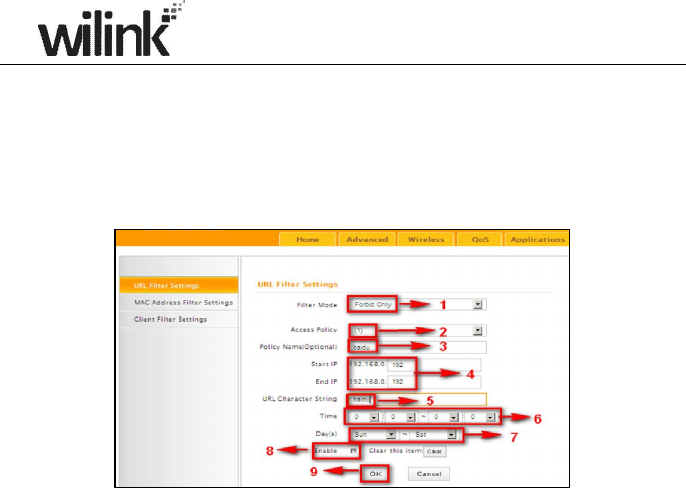
7.1 URL Filter
To better control LAN PCs, you can use the URL filter functionality to allow or
disallow such PCs to access certain websites within a specified time range.
1. Filter Mode: Select a proper filter mode, say, Forbid Only (or
Forbid/Deny).
2. Access Policy: Select an access policy number, say, 1, from the
drop-down list.
3. Policy Name: Briefly describe the current rule, say, youtube, (It can
only consist of numbers, letters, or underscore).
4. Start IP/End IP: Enter the same IP address or 2 different IP addresses
in both boxes to specify a single PC or a range of PCs for the current rule
to apply to.
5. URL Character String: Enter the domain name you wish to filter out,
say, youtube.
6. Time: Specify a time period for a current rule to take effect. If the field
is set to 0:00-0:00, the rule will be applied 24hrs/day.
7. Day(s): Select a day or several days for a current rule to take effect. If
Sun-Sat is selected, the rule will apply 7days/week.
8. Enable: Check/uncheck to enable/disable the feature.
9. OK: Click to activate your settings.
Example:
If you want to disallow all computers on your LAN to access youtube.com
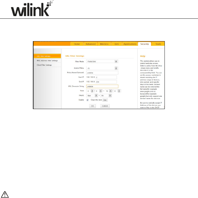
59
from 8:00 to 18:00 during working days: Monday- Friday, then do as
follows:
1. Filter Mode: Select Forbid Only.
2. Access Policy: Select an access policy number, say, 1, from the
drop-down list.
3. Policy Name: Briefly describe the current rule, say, youtube, (It can only
consist of numbers, letters, or underscore).
4. Start IP/End IP: Enter 2-254.
5. URL Character String: Enter youtube.
6. Time: Select 8:00-18:00.Day(s): Select Monday to Friday.
7. Enable: Check the Enable box.
8. OK: Click to save your settings.
Note:
Each rule can only include one domain name. Simply add more rules
accordingly, if you want to filter multiple domain names.
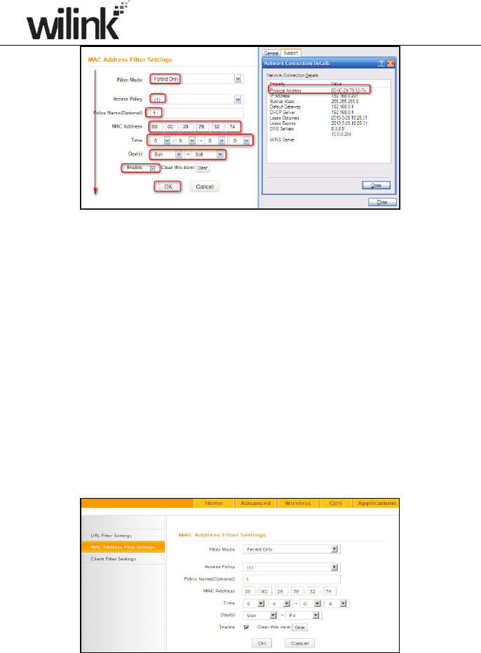
7.2 MAC Filter
This section allows you to set the times specific clients can or cannot access
the Internet via the devices’ MAC Addresses.
Forbid Only: Specify a list of devices to Forbid access to Internet. All other
devices not listed as Forbidden will be permitted.
Permit Only: Specify a list of devices to Permit access to Internet. All other
devices not listed as Permitted will be forbidden.
60
1. Filter Mode: Select a proper filter mode, say, Forbid Only (or
Forbid/Deny).
2. Access Policy: Select an access policy number, say, 1, from the
drop-down list.
3. Policy Name: Briefly describe the current rule (It can only consist of
numbers, letters, or underscore).
4. MAC Address: Specify a MAC address for a corresponding MAC filter
rule to apply to.
5. Time: Specify a time period for a current rule to take effect. If the field
is set to 0:00-0:00, the rule will be applied 24hrs/day.
6. Day(s): Select a day or several days for a current rule to take effect. If
Sun-Sat is selected, the rule will apply 7days/week.
7. Enable: Check/uncheck to enable/disable the feature.
8. OK: Click to activate your settings.
For Example:
To allow a PC at the MAC address of 00:E4:A5:44:35:69 to access Internet
61
from Monday to Friday.
1. Filter Mode: Select Permit Only.
2. Access Policy: Select an access policy number, say, 1, from the
drop-down list.
3. Policy Name: Briefly describe the current rule, say, Permit only, (It
can only consist of numbers, letters, or underscore).
4. MAC Address: Enter 00:E4:A5:44:35:69.
5. Time: Select 0 for all fields to apply the rule 24hrs/day.
6. Day(s): Select Monday to Friday.
7. Enable: Check the Enable box.
8. OK: Click to save your settings.
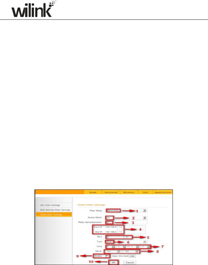
7.3 Client Filter
This section allows you to set the times specific clients can or cannot access
the Internet via the devices’ assigned IP addresses and service port.
Forbid Only (or Deny/Forbid): Only PCs listed as Forbidden (or Denied)
will be forbidden from accessing specified services; others are not restricted;
Permit Only (or Permit/Allow): Only PCs listed as permitted (or allowed)
will be permitted to access specified services; others will be forbidden.
1. Filter Mode: Select Permit Only.
2. Access Policy: Select an access policy number, say, 1, from the
drop-down list.
3. Policy Name: Briefly describe the current rule, say, 80.
62
4. Start IP/End IP: Enter the same IP address, say, 110, or 2 different IP
addresses, say, 110 and 120 in both boxes to specify a single PC or a
range of PCs for the current rule to apply to.
5. Port: Specify TCP/UDP protocol port number (s), say, 80.
6. Type (or Protocol): Select Both.
7. Time: Specify a time period for a current rule to take effect. If the field is
set to 0:00-0:00, the rule will be applied 24hrs/day.
8. Day(s): Specify a day or several days for a current rule to take effect.
9. Enable: Check/uncheck to enable/disable the feature.
10. OK: Click to activate your settings.
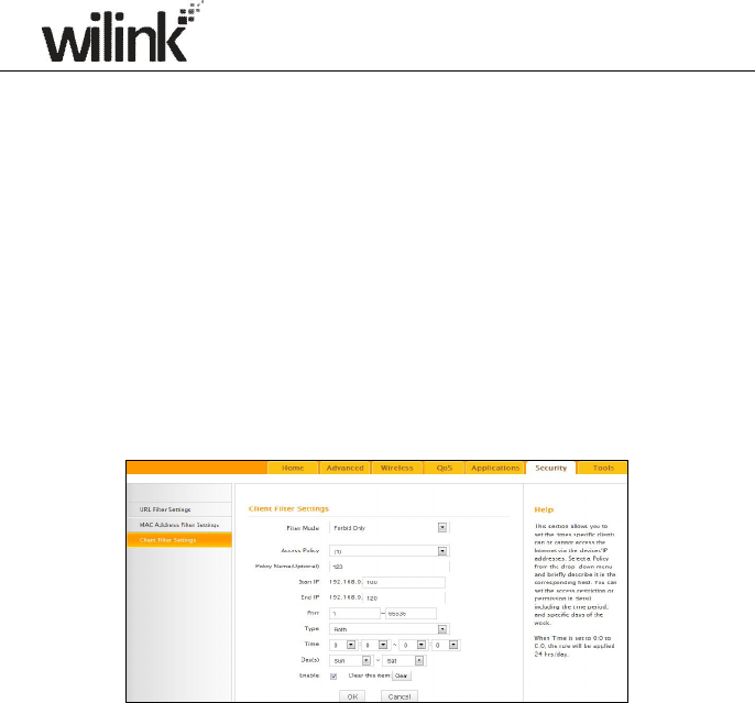
For example:
I f yo u w a n t t o p ro h ib it P C s w it h i n t he I P add re s s ra ng e o f
192.168.0.100--192.168.0.120 from accessing Internet, do as follows:
1. Filter Mode: Select Forbid Only.
2. Access Policy: Select an access policy number, say, 1, from the
drop-down list.
3. Policy Name: Briefly describe the current rule, say, 123.
4. Start IP: Enter 100.
5. End IP: Enter 120.
6. Port: Enter 1-65535 to forbid all Internet services and applications.
7. Type (or Protocol): Select Both.
8. Time: Select 0 for all fields to apply the rule 24hrs/day.
9. Day(s): Select Sun-Sat to apply the rule 7days/week.
10. Enable: Check the Enable box.
11. OK: Click to activate your settings.
63
Chapter 8 Tools
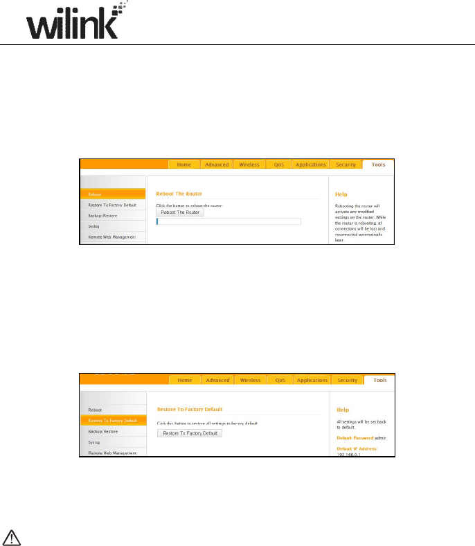
8.1 Reboot
Reboot the device to activate your settings. WAN connection will be
disconnected during reboot.
8.2. Restore to Factory Default Settings
Click the Restore to Factory Default button to reset device to factory
default settings. You need to reconfigure the device for Internet access as
well as many other settings including wireless settings.
The factory default settings are listed below:
IP Address: 192.168.0.1
Subnet mask: 255.255.255.0.
Note:
To activate your settings, you need to reboot the device after you reset it.
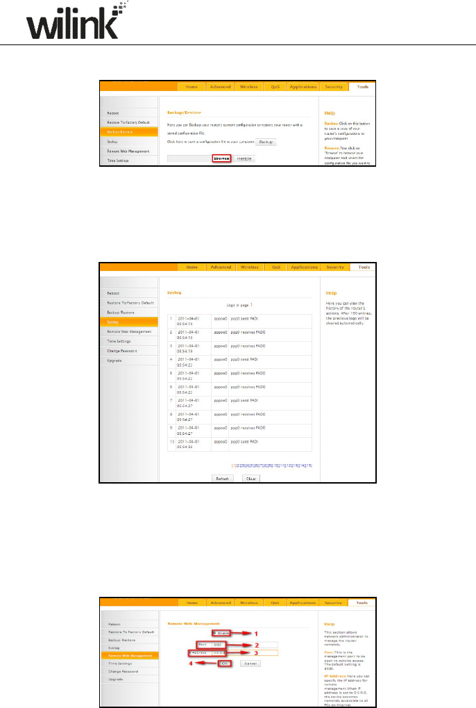
8.3 Back/Restore
Backup: Once you have configured the device the way you want it, you can
save these settings to a configuration file on your local hard drive that can
later be imported to your device in case that the device is restored to factory
default settings. To do so, follow below instructions:
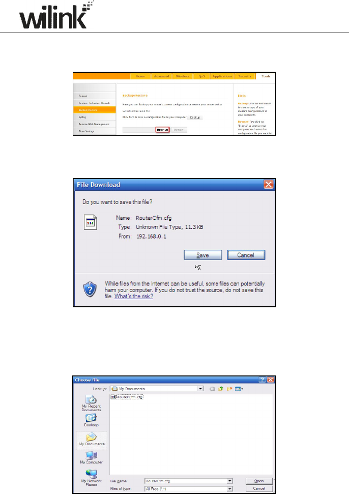
64
1. Click the Backup button and specify a directory to save settings on your
local hardware.
2. Click Save to save the configuration file.
To restore previous settings, do as follows:
Click the Browse button to locate and select a configuration file that is
saved previously to your local hard drive.
65
Click the Restore button to reset your device to previous settings.
8.4 Syslog
Here you can view the history of the device’s actions. After 150 entries, the
earliest logs will clear automatically.
8.5 Remote Web-based Management
The Remote management allows the device to be configured and managed
remotely from the Internet via a web browser.
66
1. Enable: Check/uncheck to enable/disable the DMZ host feature.
2. Port: This is the management port to be open to outside access. The
default setting is 8080. Do NOT change it unless instructed by your ISP.
3. IP Address: Here you can specify the IP Address Range for remote
management (When set to 0.0.0.0, the device becomes remotely
accessible to all the PCs on Internet or other external networks).
4. OK: Click to activate your settings.
Note:
1. To access the device via port 8080, enter "http://x.x.x.x:8080" where
"x.x.x.x" represents the the device's Internet IP address and 8080 is the
remote admin port. Assuming the device's Internet IP address is
220.135.211.56, then, simply replace the "x.x.x.x" with
"220.135.211.56" (namely, http://220.135.211.56:8080).
2. Leaving the IP address field at "0.0.0.0" makes the device remotely
accessible to all the PCs on Internet or other external networks;
populating it with a specific IP address, say, 218.88.93.33, makes the
device only remotely accessible to the PC at the specified IP address.
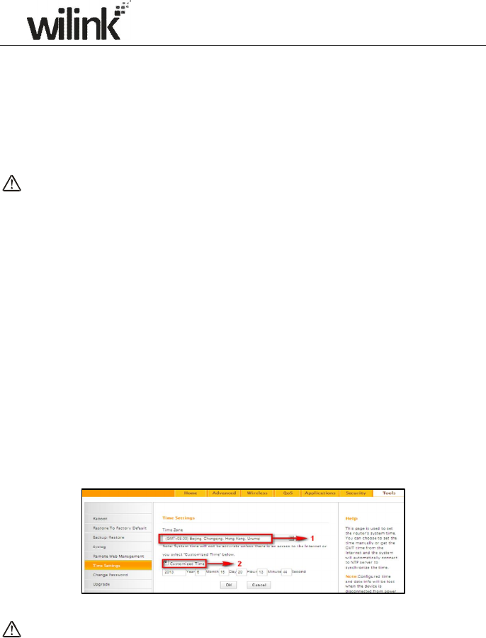
8.6 Time
This page is used to set the router’s system time. You can choose to set the
time manually or get the GMT time from the Internet and the system will
automatically connect to NTP server to synchronize the time.
Note:
Configured time and date info will be lost when the device gets disconnected
from power supply. However, it will be updated automatically when the
device reconnects to Internet. To activate time-based features (e.g. firewall),
the time and date info shall be set correctly first, either manually or
67
automatically.
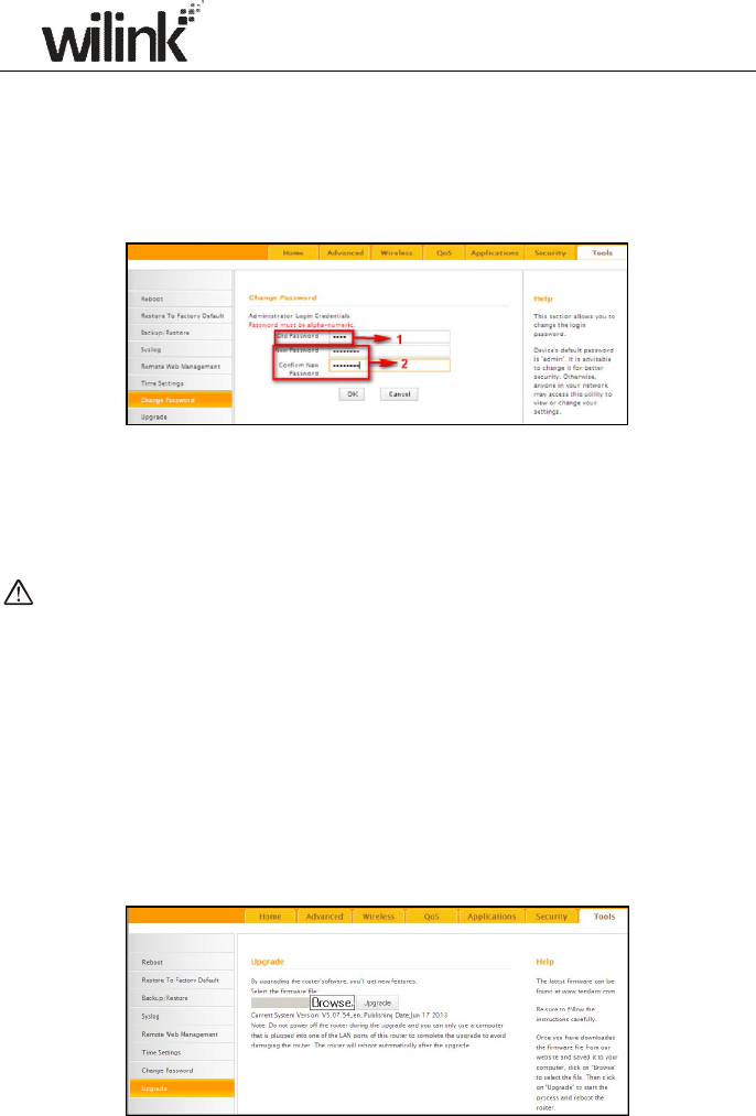
8.7 Login Password
This section allows you to change login password for accessing device’s
Web-based interface for better security.
1. New Password: Enter a new password, say, 12345 (Note that the
password can only be alphanumeric).
2. Confirm New Password: Re-enter the new password for confirmation.
3. OK: Click to activate your settings.
Note:
For security purpose, it is highly recommended that you change Device's
default login password.
8.8 Firmware Upgrade
Firmware upgrade is released periodically to improve the functionality of
your device and also to add new features. If you run into a problem with a
specific feature of the device, log on to our website (www.wilinklat.com) to
download the latest firmware to update your device.

68
1. Browse: Click to locate and select the firmware.
2. Upgrade (or Update): Click to update firmware. Device will restart
automatically when update completes.
Note:
1. Before you upgrade the firmware, making sure you are having a correct
firmware. A wrong firmware may damage the device.
2. Do NOT upgrade the firmware wirelessly or disconnect device from
power supply while firmware update is in process. Note that you need to
update the device's firmware via a wired connection.
69
Appendix 1 How to Configure IP
WIN7 OS Configuration
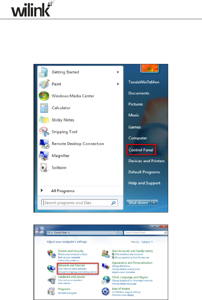
1. Click Start>Control Panel;
2. Enter Control Panel and click Network and Internet;
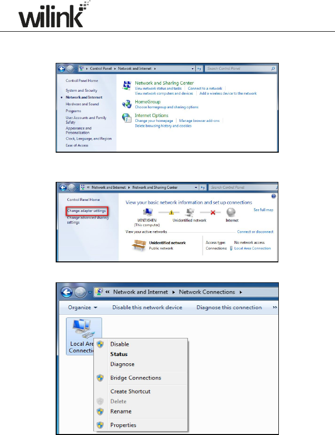
70
3. Click Network and Sharing Center;
4. Click Change adapter settings;
5. Right click Local Area Connection and select Properties;
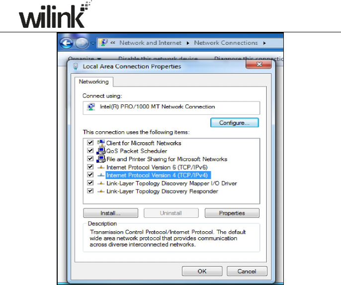
6. Select Internet Protocol Version 4(TCP/IPv4) and click Properties;
71
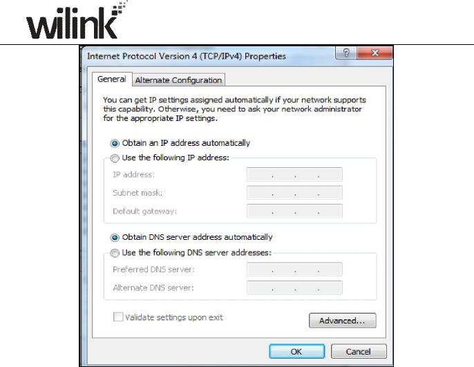
7. Select Obtain an IP address automatically and click OK to save the
configurations.
72
XP OS Configuration
1. Right click My Network Places and select Properties;
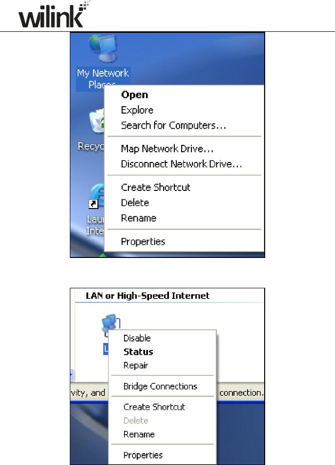
73
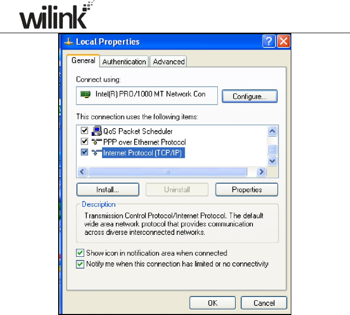
2. Right click Local and select Properties;
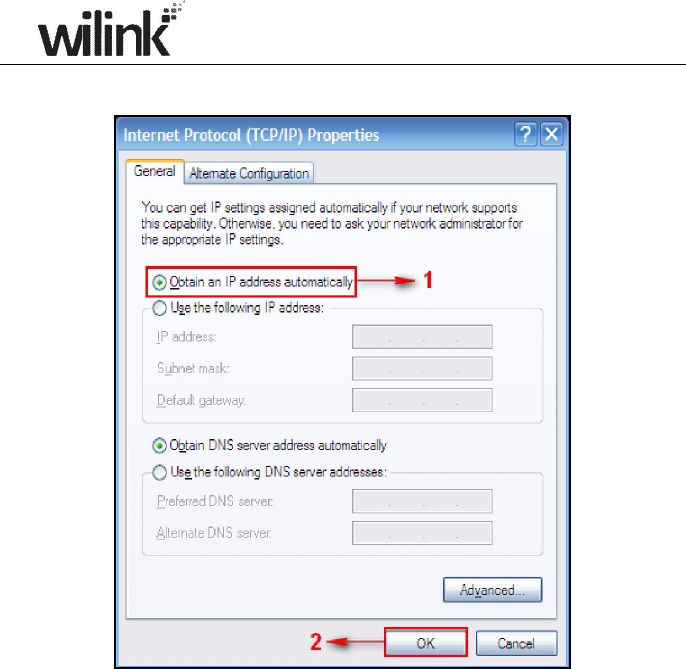
3. Select Internet Protocol(TCP/IP) and click Properties;
74
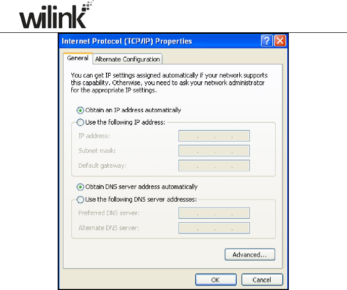
4. Select Obtain an IP address automatically and click OK to save the
settings.
75

76
Appendix 2 Glossary
Channel
A communication channel, also known as channel, refers either to a
physical transmission medium such as a wire or to a logical connection
over a multiplexed medium such as a radio channel. It is used to transfer
an information signal, such as a digital bit stream, from one or more
transmitters to one or more receivers. If there is only one AP in the range,
select any channel you like. The default is Auto.
If there are several APs coexisting in the same area, it is advisable that
you select a different channel for each AP to operate on, minimizing the
interference between neighboring APs. For example, if 3 American-
standard APs coexist in one area, you can set their channels respectively
to 1, 6 and 11 to avoid mutual interference.
SSID
Service set identifier (SSID) is used to identify a particular 802.11
wireless LAN. It is the name of a specific wireless network. To let your
wireless network adapter roam among different APs, you must set all
APs’ SSID to the same name.
WPA/WPA2
The WPA protocol implements the majority of the IEEE 802.11i standard.
It enhances data encryption through the Temporal Key Integrity Protocol
(TKIP) which is a 128-bit per-packet key, meaning that it dynamically
generates a new key for each packet. WPA also includes a message
integrity check feature to prevent data packets from being hampered
with. Only authorized network users can access the wireless network.
The later WPA2 protocol features compliance with the full IEEE 802.11i
standard and uses Advanced Encryption Standard (AES) in addition to
TKIP encryption protocol to guarantee better security than that provided
by WEP or WPA. Currently, WPA is supported by Windows XP SP1.
IEEE 802.1X Authentication
IEEE 802.1X Authentication is an IEEE Standard for port-based Network
Access Control (PNAC). It is part of the IEEE 802.1 group of networking
protocols. It provides an authentication mechanism to devices wishing to
attach to a LAN or WLAN.IEEE 802.1X defines the encapsulation of EAP

77
over LAN or EAPOL. 802.1X authentication involves three parties: a
supplicant, an authenticator, and an authentication server. The supplicant
is a client device (such as a laptop) that wishes to attach to the
LAN/WLAN - though the term 'supplicant' is also used interchangeably to
refer to the software running on the client that provides credentials to the
authenticator. The authenticator is a network device, such as an Ethernet
switch or wireless access point; and the authentication server is typically
a host running software supporting the RADIUS and EAP protocols. The
authenticator acts like a security guard to a protected network. The
supplicant (i.e. client device) is not allowed access through the
authenticator to the protected side of the network until the supplicant’s
identity has been validated and authorized. With 802.1X port-based
authentication, the supplicant provides credentials, such as user name /
password or digital certificate, to the authenticator, and the authenticator
forwards the credentials to the authentication server for verification. If
the authentication server determines the credentials are valid, the
supplicant (client device) is allowed to access resources located on the
protected side of the network.
PPPOE
The Point-to-Point Protocol over Ethernet (PPPoE) is a network protocol
for encapsulating PPP frames inside Ethernet frames. Integrated PPP
protocol implements authentication, encryption, and compression
functions that traditional Ethernet cannot provide and can also be used
in the cable modem and digital subscriber line (DSL) and Ethernet that
provide access service to the users. Essentially, it is a protocol that
allows to establish a point-to-point tunnel between two Ethernet
interfaces within an Ethernet broadcast domain.
DNS
The Domain Name System (DNS) is a hierarchical distributed naming
system for computers, services, or any resource connected to the
Internet or a private network. It associates various information with
domain names assigned to each of the participating entities. A Domain
Name Service resolves queries for these names into IP addresses for the
purpose of locating computer services and devices worldwide. An
often-used analogy to explain the Domain Name System is that it serves

78
as the phone book for the Internet by translating human-friendly
computer hostnames into IP addresses.
WDS
A wireless distribution system (WDS) is a system enabling the wireless
interconnection of access points in an IEEE 802.11 network. It allows a
wireless network to be expanded using multiple access points without
the traditional requirement for a wired backbone to link them. All base
stations in a wireless distribution system must be configured to use the
same radio channel, method of encryption (none, WEP, or WPA) and the
same encryption keys. They may be configured to different service set
identifiers. WDS also requires every base station to be configured to
forward to others in the system. WDS may also be considered a repeater
mode because it appears to bridge and accept wireless clients at the
same time (unlike traditional bridging).WDS may be incompatible
between different products (even occasionally from the same vendor)
since it is not certified by the Wi-Fi Alliance. WDS may provide two
modes of wireless AP-to-AP connectivity:
Wireless bridging, in which WDS APs communicate only with each other
and don't allow wireless clients or stations (STA) to access them.
Wireless repeating, in which APs communicate with each other and with
wireless STAs.
DMZ
In computer security, a DMZ (sometimes referred to as a perimeter
networking) is a physical or logical subnetwork that contains and
exposes an organization's external-facing services to a larger untrusted
network, usually the Internet. The purpose of a DMZ is to add an
additional layer of security to an organization's local area network (LAN);
an external attacker only has access to equipment in the DMZ, rather
than any other part of the network. Hosts in the DMZ have limited
connectivity to specific hosts in the internal network, although
communication with other hosts in the DMZ and to the external network
is allowed. This allows hosts in the DMZ to provide services to both the
internal and external network, while an intervening firewall controls the
traffic between the DMZ servers and the internal network clients. Any
services such as Web servers, Mail servers, FTP servers and VoIP servers,
etc. that are being provided to users on the external network can be

79
placed in the DMZ.

80
Appendix 3 FAQs
This section provides solutions to problems that may occur during
installation and operation of the device. Read the following if you are running
into problems. If your problem is not covered here, please feel free to go to
www.wilinklat.com to find a solution or email your problems to:
soporte@wilinklat.com. We will be more than happy to help you out as
soon as possible.
1. Q: I entered the device’s LAN IP address in the web browser but
cannot access the utility. What should I do?
1) Check whether device is functioning correctly. The SYS LED should blink
a few seconds after device is powered up. If it does not light up, then
some internal faults may have occurred.
2) Verify physical connectivity by checking whether a corresponding port’s
link LED lights up. If not, try a different cable. Note that an illuminated
light does NOT ALWAYS indicate successful connectivity.
3) Run the "ping 192.168.0.1" command. If you get replies from
192.168.0.1, open your browser and verify that Proxy server is disabled.
In case that ping fails, press and hold the "RESET" button on your device
for 7 seconds to restore factory default settings, and then run
"ping192.168.0.1" again.
4) Contact our technical support for help if the problem still exists after you
tried all the above.
2. Q: What should I do if I forget the login password to my device?
A: Reset your device by pressing the Reset button for over 7 seconds. Note:
All settings will be deleted and restored to factory defaults once you
pressed the Reset button.
3. Q: My computer shows an IP address conflict error after having
connected to the device. What should I do?
1) Check if there are other DHCP servers present in your LAN. If there are
other DHCP servers except your router, disable them immediately.
2) The default IP address of the device is 192.168.0.1; make sure this
address is not used by another PC or device. In case that two computers
or devices share the same IP addresses, change either to a different
address.
4. Q: I cannot access Internet and send/receive emails; what should
I do?

81
This problem mainly happens to users who use the PPPoE or Dynamic IP
Internet connection type. You need to change the MTU size (1492 by
default). In this case, go to “WAN Settings” to change the MTU value
from default 1480 to 1450 or 1400, etc.
5. Q: How do I share resources on my computer with users on
Internet through the device?
To let Internet users access internal servers on your LAN such as e-mail
server, Web, FTP, via the device, use the "Virtual Server" feature. To do so,
follow steps below:
Step 1: Create your internal server, make sure the LAN users can access
these servers and you need to know related service ports, for example, port
number for Web server is 80; FTP is 21; SMTP is 25 and POP3 is 110.
Step 2: Enter Port Forwarding (also called Port Range Forwarding on
some products) screen from device web UI.
Step 3: Complete the Start Port (also called External/Ext Port on some
products) and End Port (also known as Internal Port on some products) fields,
say, 80-80.
Step 4: Input the internal server’s IP address. For example, assuming
that your Web server’s IP address is 192.168. 0.10, then simply input it.
Step 5: Select a proper protocol type: TCP, UDP, or Both depending on
which protocol(s) your internal host is using.
Step 6: Click Enable and save your settings.
For your reference, we collected a list of some well-known service ports
as follows:
Server
Protoco
l Service Port
Web Server
TCP
80
FTP Server
TCP
21
Telnet
TCP
23
Net Meeting TCP 1503、1720
MSN Messenger TCP/UD
P
File Sen
d:6891
-
6900(TCP)
Voice:1863, 6901(TCP)
Voice:1863, 5190(UDP)
PPTP VPN
TCP
1723
Iphone5.0
TCP
22555
SMTP
TCP
25
POP3
TCP
110
82
Appendix 4 Remove Wireless Network from Your
PC
If you change wireless settings on your wireless device, you must remove
them accordingly your PC; otherwise, you may not be able to wirelessly
connect to the device. Below describes how to do remove a wireless
network from your PC.
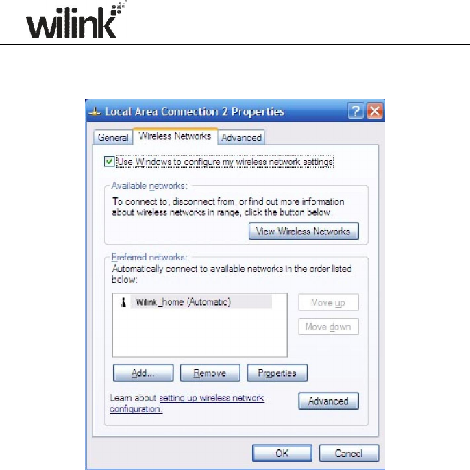
If you are using Windows XP, do as follows:
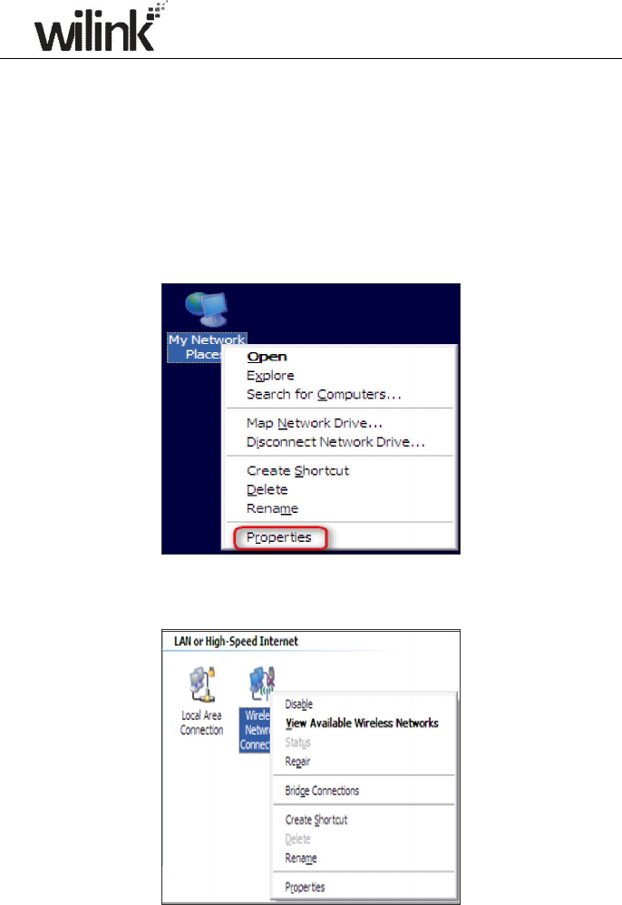
1. Right click My Network Places and select Properties.
2. Click Wireless Network Connection and then select Properties.
83
3. Click Wireless Networks, select the item under Preferred networks
and then click the Remove button.
If you are using Windows 7, do as follows:
1. Click Network from your desktop and select Properties.
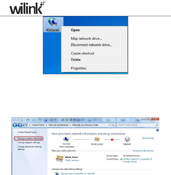
84
2. Select Manage Wireless Networks.
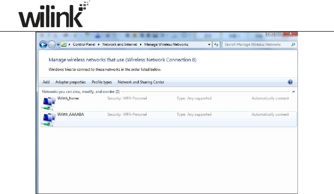
3. Click the wireless connection and select Remove network.
85

86
Appendix 5 Safety and Emission Statement
CE Mark Warning
This is a Class B product In a domestic environment, this product may
cause radio interference, in which case the user may be required to take
adequate measures. This device complies with EU 1999/5/EC.
FCC Statement
This device complies with Part 15 of the FCC Rules. Operation is subject
to the following two conditions: (1) This device may not cause harmful
interference, and (2) this device must accept any interference received,
including interference that may cause undesired operation.
This equipment has been tested and found to comply with the limits for a
Class B digital device, pursuant to Part 15 of the FCC Rules. These limits
are designed to provide reasonable protection against harmful
interference in a residential installation. This equipment generates, uses
and can radiate radio frequency energy and, if not installed and used in
accordance with the instructions, may cause harmful interference to
radio communications. However, there is no guarantee that interference
will not occur in a particular installation. If this equipment does cause
harmful interference to radio or television reception, which can be
determined by turning the equipment off and on, the user is encouraged
to try to correct the interference by one of the following measures:
- Reorient or relocate the receiving antenna.
- Increase the separation between the equipment and receiver.
- Connect the equipment into an outlet on a circuit different from that to
which the receiver is connected.
- Consult the dealer or an experienced radio/TV technician for help.
FCC Caution: Any changes or modifications not expressly approved by
the party responsible for compliance could void the user's authority to
operate this equipment.
This transmitter must not be co-located or operating in conjunction with
any other antenna or transmitter.
The manufacturer is not responsible for any radio or TV interference
caused by unauthorized modifications to this equipment.
Radiation Exposure Statement

87
This equipment complies with FCC radiation exposure limits set forth for an
uncontrolled environment. This equipment should be installed and operated
with minimum distance 20cm between the radiator & your body.
Note:
1. The manufacturer is not responsible for any radio or TV interference
caused by unauthorized modifications to this equipment.
2. To avoid unnecessary radiation interference, it is recommended to use a
shielded RJ45 cable