TECHVIEW R300T Router inalambrico N300 User Manual Part One
TECHVIEW,INC Router inalambrico N300 Users Manual Part One
TECHVIEW >
Contents
- 1. Users Manual Part One
- 2. Users Manual Part Two
Users Manual Part One

User Guide
www.wilinklat.com

Copyright Statement
is the registered trademark of Techview Inc. All the
products and product names mentioned herein are the trademarks or
registered trademarks of their respective holders. Copyright of the whole
product as integration, including its accessories and software, belongs to
Techview Inc. Without prior expressed written permission from Techview
Inc., any individual or party is not allowed to copy, plagiarize, reproduce,
or translate it into other languages.
All photos and product specifications mentioned in this manual are
for references only. Upgrades of software and hardware may occur;
Wilink reserves the right to revise this publication and to make changes in
the content hereof without obligation to notify any person or organization
of such revisions or changes. If you would like to know more about our
product information, please visit our website at
http://www.wilinklat.com.

Table of Contents
TABLE OF CONTENTS…………………………………………........................2
CHAPTER 1 PRODUCT OVERVIEW……………………………………………………1
1.1 PACKAGE CONTENTS………………………………………………………………………………………………1
1.2 GETTING TO KNOW YOUR ROUTER……………………………………………………………………………1
CHAPTER 2 INSTALLATION AND QUICK SETUP GUIDE…………………………5
2.1 PREPARATION………………………………………………………………………………………………………5
2.2 PHYSICAL INSTALLATION…………………………………………………………………………………………5
2.3 INTERNET CONNECTION SETUP……………………………………………………………………………….7
2.3.1 Use Standard TCP/IP Properties for DHCP……………………………………………………7
2.3.2 Log in to Web Manager………………………………………………………………………………….7
2.3.3 Quick Internet Connection Setup………………………………………………………………….8
2.3.4 Verify Internet Connection Settings………………………………………………………………9
2.3.5 Wireless Settings…………………………………………………………………………………………11
2.3.6 Connect to Device Wirelessly……………………………………………………………………12
CHAPTER 3 ADVANCED SETTINGS…………………………………………………20
3.1 STATUS……………………………………………………………………………………………………………20
3.2 INTERNET CONNECTION SETUP……………………………………………………………………………21
3.2.1 PPPoE……………………………………………………………………………………………………………21
3.2.2 Static IP………………………………………………………………………………………………………22
3.2.3 DHCP……………………………………………………………………………………………………………23
3.2.4 PPTP……………………………………………………………………………………………………………24
3.2.5 L2TP……………………………………………………………………………………………………………25
3.3 MAC CLONE……………………………………………………………………………………………………….26
3.4 WAN SPEED………………………………………………………………………………………………………26
3.5 WAN MEDIUM TYPE……………………………………………………………………………………………27
3.6 LAN SETTINGS……………………………………………………………………………………………………30
3.7 DNS SETTINGS…………………………………………………………………………………………………30
3.8 DHCP……………………………………………………………………………………………………………….31
3.9 DHCP CLIENT LIST……………………………………………………………………………………………31
CHAPTER 4 WIRELESS SETTINGS……………………………………………………33
4.1 WIRELESS BASIC SETTINGS………………………………………………………………………………….33
4.1.1 Wireless AP Mode…………………………………………………………………………………………33
4.1.2 WDS Bridge Mode………………………………………………………………………………………35
4.2 WIRELESS SECURITY……………………………………………………………………………………………43
4.3 WIRELESS ACCESS CONTROL………………………………………………………………………………46
4.4 WIRELESS CLIENT………………………………………………………………………………………………47
CHAPTER 5 BANDWIDTH CONTROL…………………………………………………49
5.1 BANDWIDTH CONTROL…………………………………………………………………………………………49
5.2 TRAFFIC STATISTICS……………………………………………………………………………………………50
CHAPTER 6 SPECIAL APPLICATIONS………………………………………………52

6.1 PORT RANGE FORWARDING…………………………………………………………………………………52
6.2 DMZ HOST………………………………………………………………………………………………………53
6.3 DDNS………………………………………………………………………………………………………………54
6.4 UPNP………………………………………………………………………………………………………………55
6.5 STATIC ROUTING…………………………………………………………………………………………………56
6.6 ROUTING TABLE…………………………………………………………………………………………………57
CHAPTER 7 SECURITY…………………………………………………………………58
7.1 URL FILTER………………………………………………………………………………………………………58
7.2 MAC FILTER………………………………………………………………………………………………………59
7.3 CLIENT FILTER……………………………………………………………………………………………………61
CHAPTER 8 TOOLS………………………………………………………………………63
8.1 REBOOT……………………………………………………………………………………………………………63
8.2. RESTORE TO FACTORY DEFAULT SETTINGS……………………………………………………………63
8.3 BACK/RESTORE…………………………………………………………………………………………………63
8.4 SYSLOG……………………………………………………………………………………………………………65
8.5 REMOTE WEB-BASED MANAGEMENT………………………………………………………………………65
8.6 TIME…………………………………………………………………………………………………………………66
8.7 LOGIN PASSWORD………………………………………………………………………………………………67
8.8 FIRMWARE UPGRADE……………………………………………………………………………………………67
APPENDIX 1 HOW TO CONFIGURE IP………………………………………………69
WIN7 OS CONFIGURATION……………………………………………………………………………………69
XP OS CONFIGURATION…………………………………………………………………………………………72
APPENDIX 2 GLOSSARY…………………………………………………………………76
APPENDIX 3 FAQS………………………………………………………………………80
APPENDIX 4 REMOVE WIRELESS NETWORK FROM YOUR PC……………82
APPENDIX 5 SAFETY AND EMISSION STATEMENT……………………………86
1
Chapter 1 Product Overview
1.1 Package Contents
Unpack the box and verify the package contains the following items:
Power Adapter
Installation Guide
Resource CD(including User Guide, Quick Install Guide, and setup
wizard)
Ethernet Cable
If any of the above items is incorrect, missing, or damaged, please contact
your Wlink reseller for immediate replacement.
1.2 Getting to know your router
Before you cable your router, take a moment to become familiar with the
front and back panels and the label. Pay particular attention to the LEDs on
the front panel.
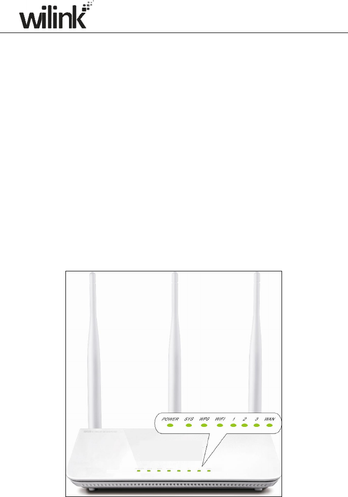
Front Panel
Router inalámbrico N300

2
Front LED Overview
LED Status
Description
Power
Solid
Indicates a proper connection to the power
supply
Off Indicates an improper connection to the power
adapter
SYS Blinking
Indicates system is functioning properly
WPS
Solid
WPS is enabled
Blinking
Device is performing WPS authentication on a
client device
Off WPS is disabled or WPS negotiation is finished
WIFI
Solid
Wireless is enabled
Blinking
Transferring data
Off Wireless is disabled
LAN(1/2/3)
Solid
LAN port connected correctly
Blinking
LAN port is transferring data
Off LAN port connected incorrectly
WAN
Solid
WAN port connected correctly
Blinking
WAN port is transferring data
Off WAN port connected incorrectly
3
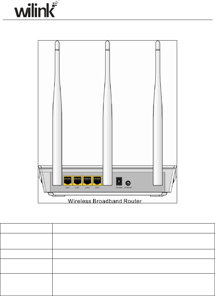
Back Panel
Back LED Overview
Port Description
WAN Usually for connecting DSL MODEM、CABLE MODEM、ISP to
the Internet.
LAN(1/2/3) Usually for connecting computers, switches .etc.
POWER The power adapter is connected and you can use the provided
adapter to supply power.
WPS/ RESET
When you press this button for 7 seconds, files set by the router
will be deleted and restored to default factory settings; for 1 second,
WPS will be enabled and the WPS LED will be blinking accordingly.
1.3 Position your Router

4
The router lets you access your network from virtually anywhere within the
operating range of your wireless network. However, the operating distance
or range of your wireless connection can vary significantly depending on the
physical placement of your router. For example, the thickness and number of
walls the wireless signal passes through can limit the range. For best results,
place your router:
• Near the center of the area where your computers and other devices
operate, and preferably within line of sight to your wireless devices.
• So it is accessible to an AC power outlet and near Ethernet cables for
wired computers.
• In an elevated location such as a high shelf, keeping the number of
walls and ceilings between the router and your other devices to a minimum.
• Away from electrical devices that are potential sources of interference.
Equipment that might cause interference includes ceiling fans, home
security systems, microwaves, PCs, the base of a cordless phone, or a
2.4-GHz cordless phone.
• Away from any large metal surfaces, such as a solid metal door or
aluminum studs. Large expanses of other materials such as glass, insulated
walls, fish tanks, mirrors, brick, and concrete can also affect your wireless
signal.

5
Chapter 2 Installation and Quick Setup Guide
2.1 Preparation
Before connecting Ethernet cables,please verify the following items:
Item Description
Wireless Router Used with the provided power supply
PC Installed with IE8 or other better web browsers.
Ethenet Cable Used for linking the PC to the router
Broadband Service Provided by ISP
Internet Connection
Setup
If you connect to the Internet using a broadband
connection that requires a username and a
password provided by your ISP, please select
PPPoE;
If your ISP provides all the needed information:
IP address, subnet mask, gateway address, and
DNS address(es), please select Static IP;
If you can access Internet as soon as your
computer directly connects to an
Internet-enabled ADSL/Cable modem, please
select DHCP;
If your ISP uses a PPTP connection, please select
PPTP;
If your ISP uses an L2TP connection, please
select L2TP..
2.2 Physical installation
1. Connect one end of the included power adapter to the device and plug the
other end into a wall outlet nearby.(Using a power adapter with a different
voltage rating than the one included with the device will cause damage to
the device.)
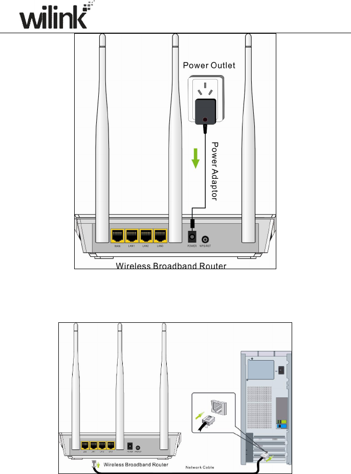
6
2. Connect one of the LAN ports on the Device to the NIC port on your PC
using an Ethernet cable.
3. Connect the Ethernet cable from Internet side to the WAN port on the
Device.
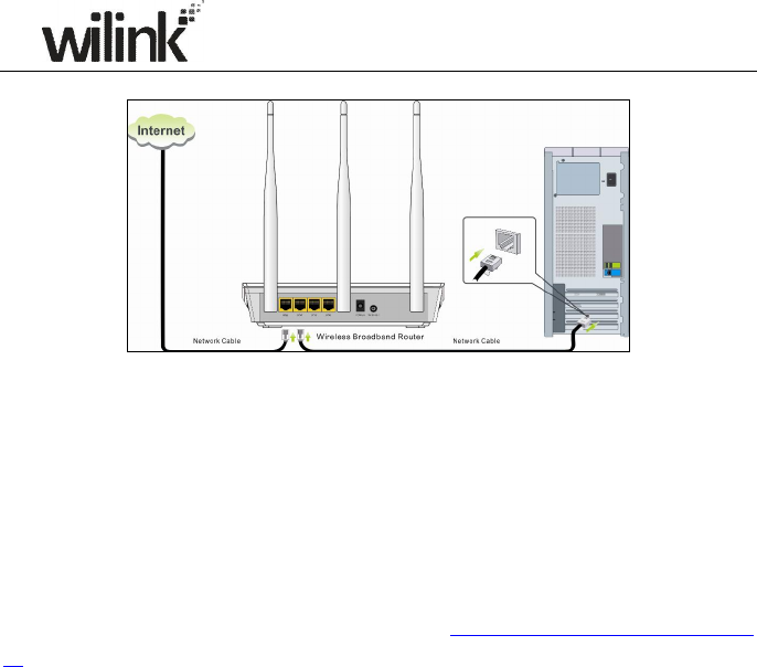
7
4. When connected, log in to Web manager to set up Internet connection.
2.3 Internet Connection Setup
Before you start the setup process, get your ISP information and make sure
the computers and devices in the network have the settings described here.
2.3.1 Use Standard TCP/IP Properties for DHCP
If you set up your computer to use a static IP address, change the settings
so that it uses Dynamic Host Configuration Protocol (DHCP).
If you are not
clear about this configuration, please refer to Appendix 1: How to Configure
IP.
.
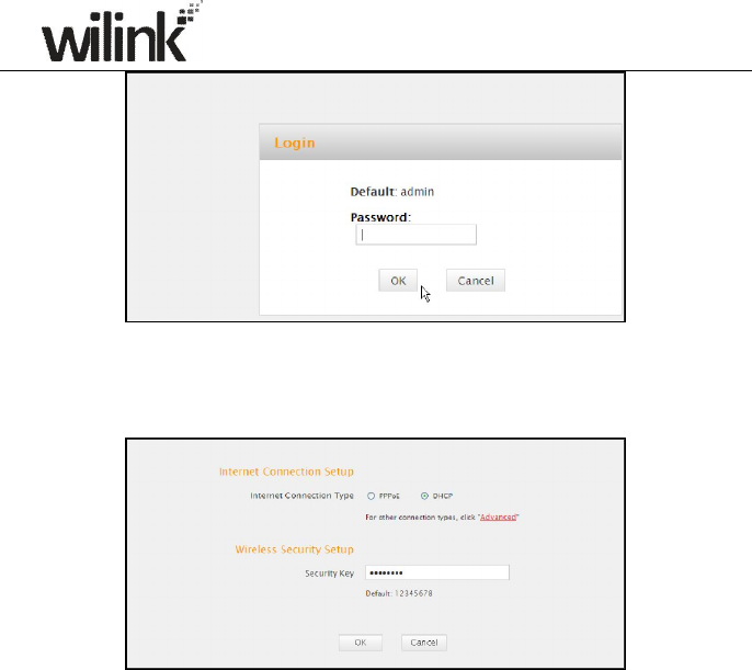
2.3.2 Log in to Web Manager
1. 1). Launch a web browser; in the address bar, input 192.168.0.1 and
press Enter;
2). Enter admin in the password field on the appearing login window and
then click OK.
8
2. Now you may access the device’s home page for quickly setting up
Internet connection and wireless security.
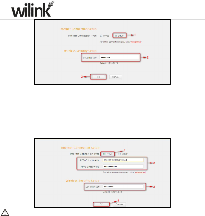
2.3.3 Quick Internet Connection Setup
2 common Internet connection types are available on the home page:
PPPoE and DHCP.
DHCP: Select DHCP (Dynamic IP) if you can access Internet as soon as your
computer directly connects to an Internet-enabled ADSL/Cable modem;
configure a security key (8-63 characters) to secure your wireless network
and then click OK.
9
PPPoE: Select PPPoE (Point to Point Protocol over Ethernet) if you used to
connect to the Internet using a broadband connection that requires a
username and a password. Enter the user name and password provided by
your ISP; configure a security key to secure your wireless network and then
click OK.
Note:
1. DHCP is the default Internet connection type;
2. If you are not sure about your PPPoE username and password, contact
your Internet service provider (ISP) for help. For other Internet
connection types, please go to section 3.2: Internet Connection Setup.
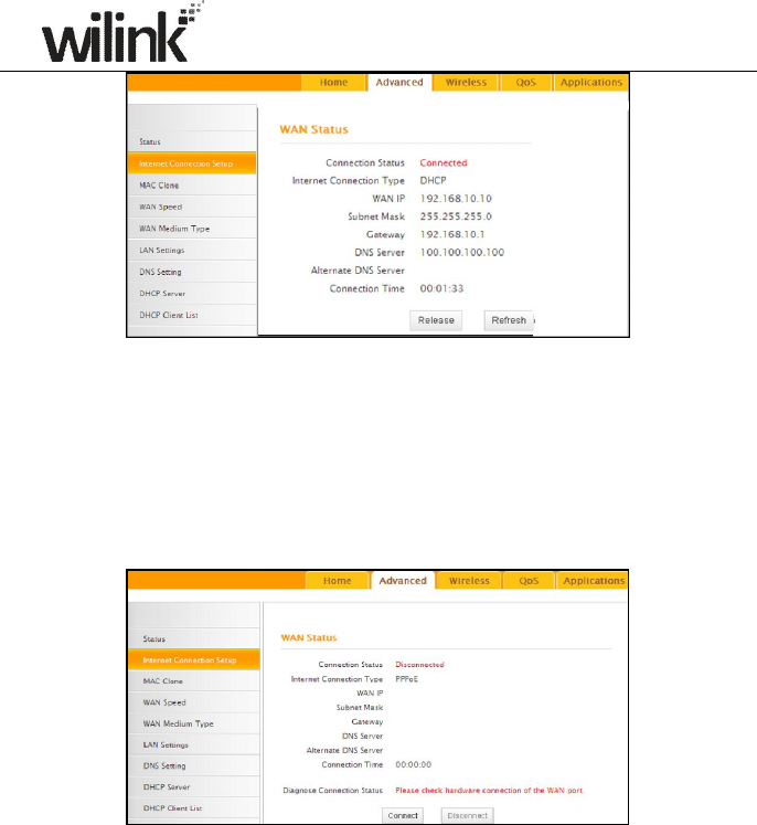
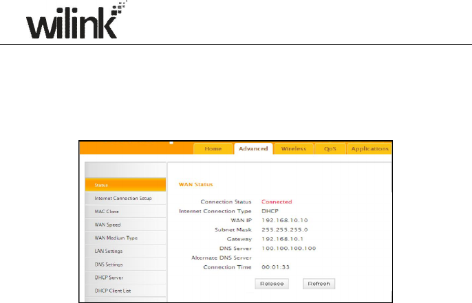
2.3.4 Verify Internet Connection Settings
System automatically skips to the status page when you finish all needed
settings on the home page. Here you can see the system status and WAN
connection status of the device.
1. If you find "Connected" and a WAN IP address displayed there (as
shown below), you have got a wired internet access now.
10
2. If connection status displays "Disconnected" and there is no WAN IP
address displayed (as seen below), connection between the
Internet-enabled modem and your device may have failed. Please
double check or re-connect all involved devices and cables properly and
then refresh the page. If nothing is wrong, "Connecting" or "Connected"
will be displayed.
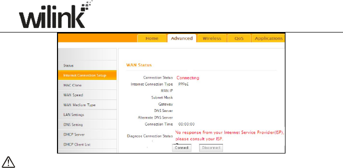
3. If "Connecting" is displayed and no WAN IP address is seen, try
refreshing the page five times. And if it still displays "Connecting" try
steps below:
1). Contact your ISP for assistance if you are using the DHCP connection
type.
2). Read the connection diagnostic info on WAN status.
11
Note:
Below diagnostic info will be displayed on particular occasions for your
reference:
1). You have connected to Internet successfully.
2). You might have entered a wrong user name and/or a wrong password.
Please contact your ISP for the correct user name and password and
enter them again.
3). Ethernet cable is not connected or not properly connected to the WAN
port on the device. Please reconnect it properly.
4). No response is received from your ISP. Please verify that you can access
Internet when you directly connect your PC to an Internet-enabled
modem. If not, contact your local ISP for help.
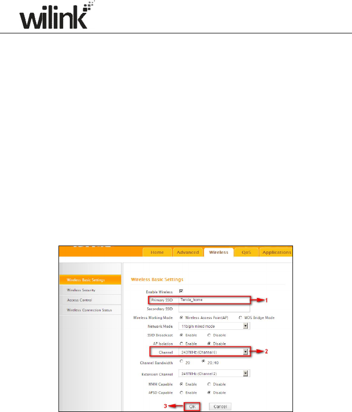
2.3.5 Wireless Settings
Wireless Basic Settings
If you want to create a WLAN for sharing Internet connection, simply click
Wireless-> Wireless Basic Settings. Change the SSID, you can name it
whatever you like. Select 2437MHz (channel 6) and leave other options
unchanged and then click OK.
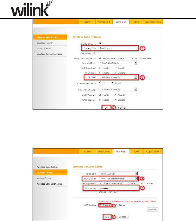
12
Wireless Security Settings
If you want to encrypt your wireless network, click Wireless Security,
disable WPS, specify a security key of down to 8 characters, and then click
OK.
2.3.6 Connect to Device Wirelessly
Having finished above settings, you can search the device's wireless network
(SSID) from your wireless devices (notebook, iPad, iPhone, etc) and enter a
security key to connect to it wirelessly.
1. If you are using Windows XP OS, do as follows:
1) Click Start and select Control Panel.
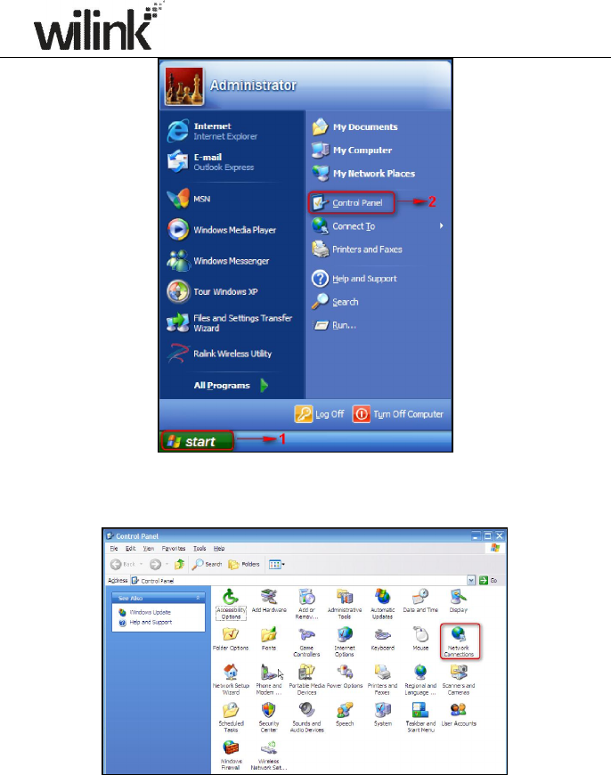
13
2) Click Network Connections.
3) Right click Wireless Network Connection and then select View
Available Wireless Networks.
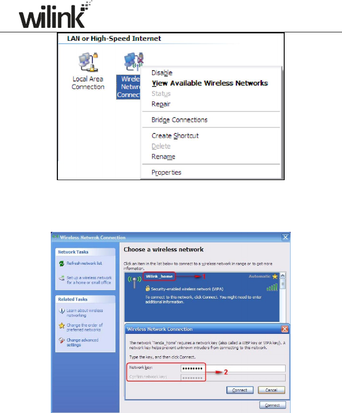
14
4) Select the desired wireless network, click Connect, enter the security
key and then click OK.
5) You can access Internet via the device when "Connected" appears next
to the wireless network name you selected.
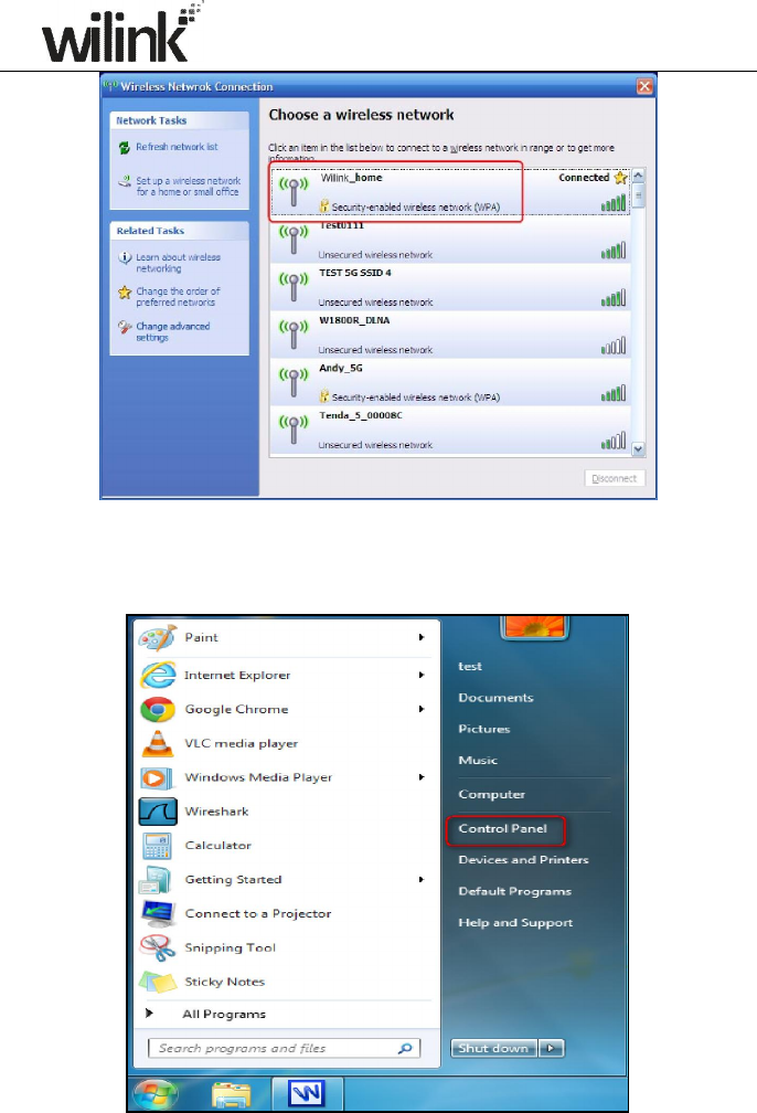
15
2. If you are using Windows 7 OS, do as follows:
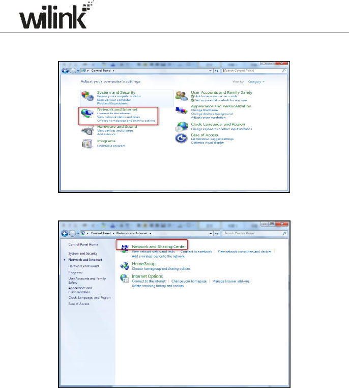
1) Click Start and select Control Panel.
16
2) Click Network and Internet.
3) Click Network and Sharing Center.
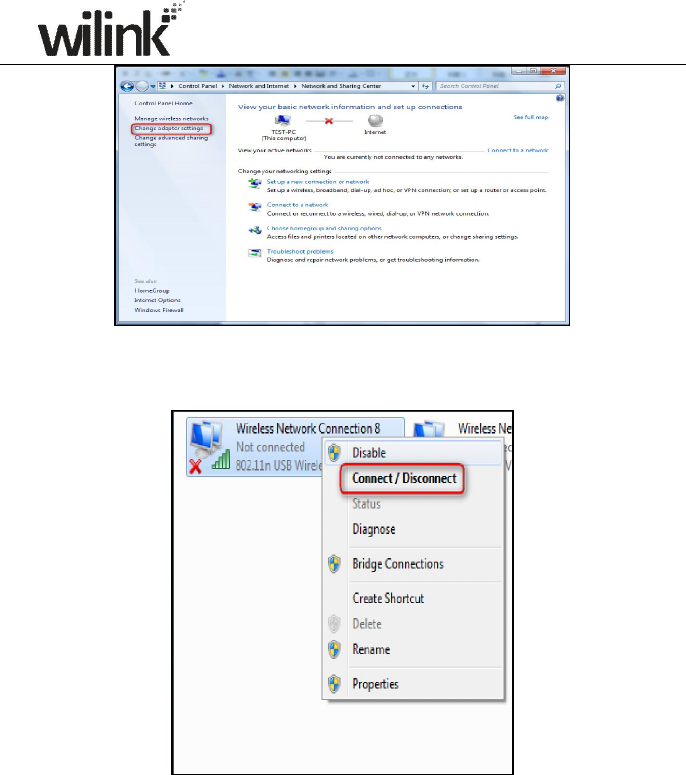
4) Click Change adapter settings.
17
5) Select a desired wireless connection and click Connect/Disconnect.
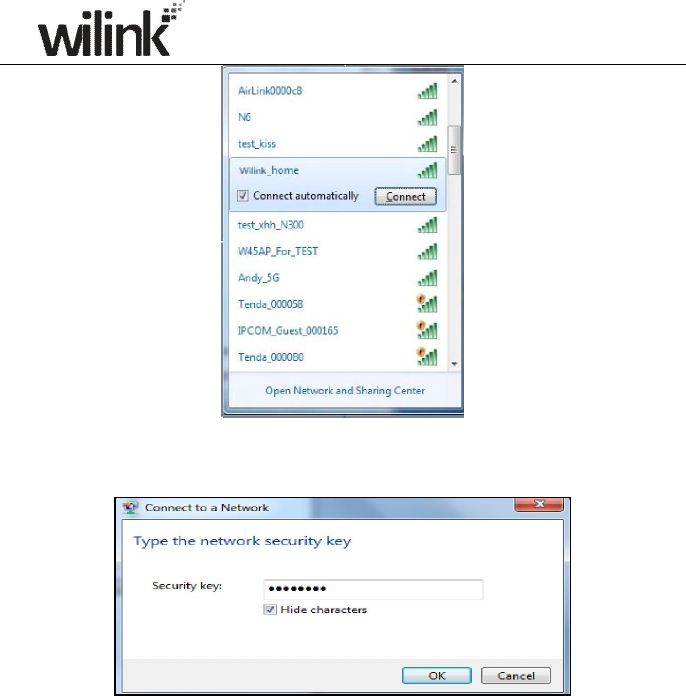
6) Select the wireless network you wish to connect and click Connect.
18
7) Enter the security key and click OK.
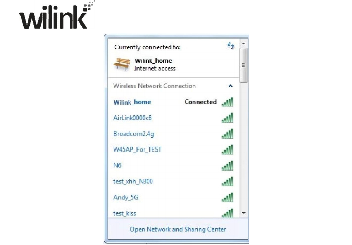
8) You can access Internet via the device when "Connected" appears next
to the wireless network name you selected.
19
20
Chapter 3 Advanced Settings
3.1 Status
Here you can see at a glance the operating status of the device.
1. Connection Status: Displays WAN connection status: Disconnected,
Connecting or Connected.
2. Disconnected: Indicates that the Ethernet cable from your ISP side is
not correctly connected to device's WAN port or the router is not logically
connected to your ISP.
3. Connecting: Indicates that the WAN port is correctly connected and is
requesting an IP address from your ISP.
4. Connected: Indicates that the router has been connected to your ISP.
5. Internet Connection Type: Displays current Internet connection type.
6. WAN IP: Displays the WAN IP address.
7. Subnet Mask: Displays WAN subnet mask provided by your ISP.
8. Gateway: Displays WAN gateway address.
9. DNS Server: Displays the preferred WAN DNS address.
10. Alternate DNS Server: Displays the alternate WAN DNS address if any.
11. Connection Time: Time duration since the device has been successfully
connected to ISP.
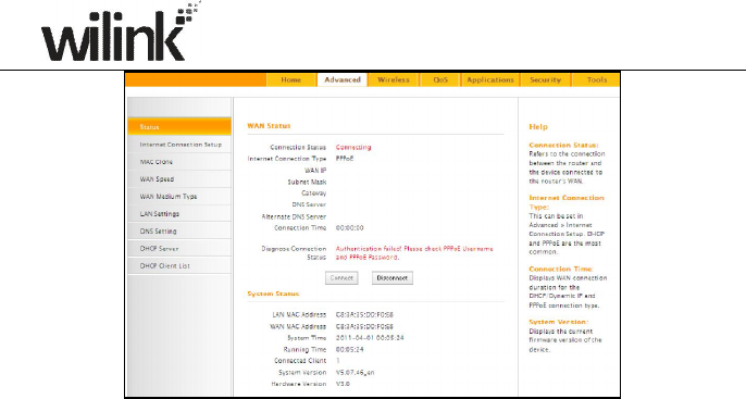
21
1. LAN MAC Address: Displays device’s LAN MAC address.
2. WAN MAC Address: Displays device’s WAN MAC address.
3. System Time: Displays device’s system time either customized or
obtained from Internet.
4. Up Time: Displays device's uptime.
5. Connected Client(s): Displays the number of connected network
devices (which obtain IP addresses from device DHCP server).
6. Firmware Version: Displays Device’s current firmware version.
7. Hardware Version: Displays Device’s current hardware version.
3.2 Internet Connection Setup
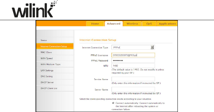
3.2.1 PPPoE
Select PPPoE (Point to Point Protocol over Ethernet) if you used to connect to
the Internet using a broadband connection that requires a username and a
password and enter the user name and password provided by your ISP.
22
1. Internet connection Type: Select PPPoE.
2. PPPoE User Name: Enter the User Name provided by your ISP.
3. PPPoE Password: Enter the password provided by your ISP.
4. MTU: Maximum Transmission Unit. DO NOT change it from the factory
default of 1492 unless necessary. You may need to change it for optimal
performance with some specific websites or application software that
cannot be opened or enabled; in this case, try 1450, 1400, etc.
5. Service Name: Description of PPPoE connection. Leave blank unless
otherwise required.
6. Server Name: Description of server. Leave blank unless otherwise
required.
7. Connect Automatically: Connect automatically to the Internet after
rebooting the system or connection failure.
Connect Manually: Require the user to manually connect to the Internet
before each session.
Connect On Demand: Re-establish connection to the Internet only when
there is data transmission.
Connect During Specified Time Period: Only connect to Internet during
a specified time period.
8. OK: Click it to save all your settings.
3.2.2 Static IP
Select Static IP if your ISP provides all the needed info. You will need to
enter the provided IP address, subnet mask, gateway address, and DNS

23
address(es) in corresponding fields.
1. Internet connection Type: Select Static IP.
2. IP Address: Enter the IP address provided by your ISP. Consult your
ISP if you are not clear.
3. Subnet mask: Enter the subnet mask provided by your ISP.
4. Gateway: Enter the WAN Gateway provided by your ISP. Consult your
ISP if you are not clear.
5. DNS Server: Enter the DNS address provided by your ISP.
6. Alternate DNS Server: Enter the other DNS address if your ISP
provides 2 such addresses (optional).
7. OK: Click it to save all your settings.
3.2.3 DHCP
Select DHCP (Dynamic IP) if you can access Internet as soon as your
computer directly connects to an Internet-enabled ADSL/Cable modem.
24
1. Internet connection Type: Select DHCP.
2. MTU: Maximum Transmission Unit. DO NOT change it from the factory
default of 1500 unless instructed by your ISP. You may need to change it
for optimal performance with some specific websites or application
software that cannot be opened or enabled; in this case, try 1450, 1400,
etc.
3. OK: Click it to save your settings.
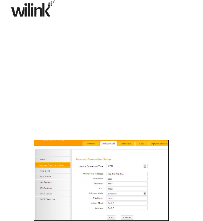
3.2.4 PPTP
PPTP: Select PPTP (Point-to-Point-Tunneling Protocol) if your ISP uses a PPTP
connection. The PPTP allows you to connect a router to a VPN server.
For example:
A corporate branch and headquarter can use this connection type to
implement mutual and secure access to each other’s resources.
1. Internet connection Type: Displays the current Internet connection
type.
2. PPTP Server Address: Enter the IP address of a PPTP server.
3. User Name: Enter your PPTP User Name.
4. Password: Enter the password.
5. MTU: Maximum Transmission Unit. DO NOT change it from the factory
default of 1492 unless instructed by your ISP. You may need to change it
for optimal performance with some specific websites or application
software that cannot be opened or enabled; in this case, try 1450, 1400,
etc.
25
6. Address Mode: Select "Dynamic" if you don’t get any IP info from your
ISP, otherwise select "Static". Consult your ISP if you are not clear.
7. IP Address: Enter the IP address provided by your ISP. Consult your
ISP if you are not clear.
8. Subnet mask: Enter the subnet mask provided by your ISP.
9. Gateway: Enter the WAN Gateway provided by your ISP. Consult your
ISP if you are not clear.
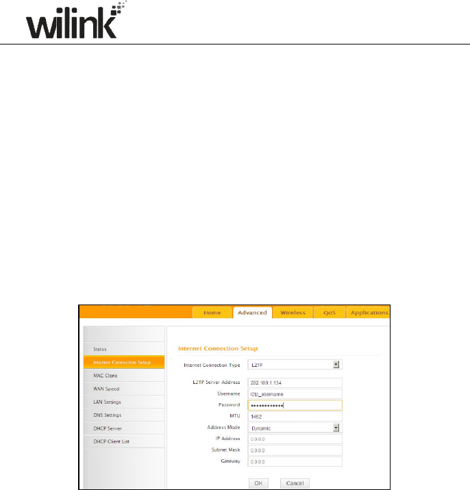
3.2.5 L2TP
Select L2TP (Layer 2 Tunneling Protocol) if your ISP uses an L2TP connection.
The L2TP connects your router to a L2TP server.
For Example:
A corporate branch and headquarter can use this connection type to
implement mutual and secure access to each other’s resources.
1. Internet connection Type: Displays the current Internet connection
type.
2. L2TP Server Address: Enter the IP address of a L2TP server.
3. User Name: Enter your L2TP username.
4. Password: Enter the password.
5. MTU: Maximum Transmission Unit. DO NOT change it from the factory
default of 1492 unless instructed by your ISP. You may need to change it
for optimal performance with some specific websites or application
software that cannot be opened or enabled; in this case, try 1450, 1400,
etc.
26
6. Address Mode: Select "Dynamic" if you don’t get any IP info from your
ISP, otherwise select "Static". Consult your ISP if you are not clear.
7. IP Address: Enter the IP address provided by your ISP. Consult your
ISP if you are not clear.
8. Subnet mask: Enter the subnet mask provided by your ISP.
9. Gateway: Enter the WAN Gateway provided by your ISP. Consult your
ISP if you are not clear.
Note:
1. PPPOE, PPTP and L2TP cannot be used simultaneously!
2. For PPTP and L2TP Internet connections, only Static IP or Dynamic
IP is available.
3. Note that PPTP and L2TP may not be available on some products.
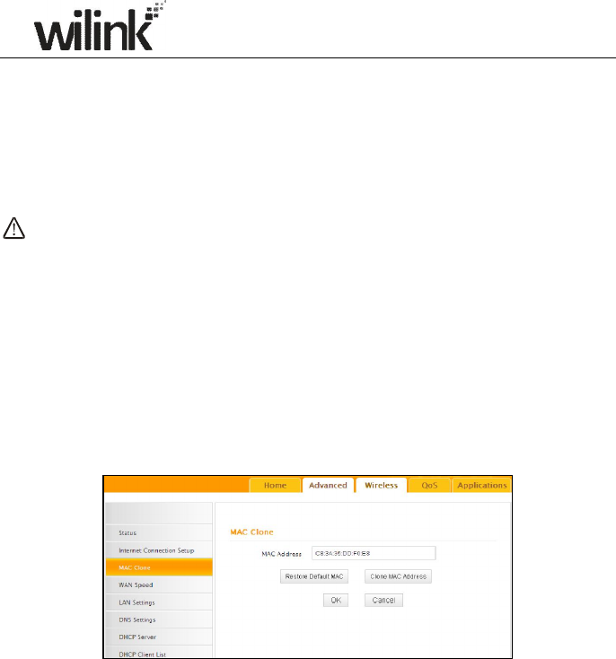
3.3 MAC Clone
This section allows you to configure Device’s WAN MAC address.
1. MAC Address: Config device’s WAN MAC address.
2. Clone MAC Address: Click to copy your PC's MAC address to the device
as a new WAN MAC address.
3. Restore Default MAC: Reset device’s WAN MAC to factory default.
3.4 WAN Speed
Here you can set the speed and duplex mode for WAN port. It is advisable to
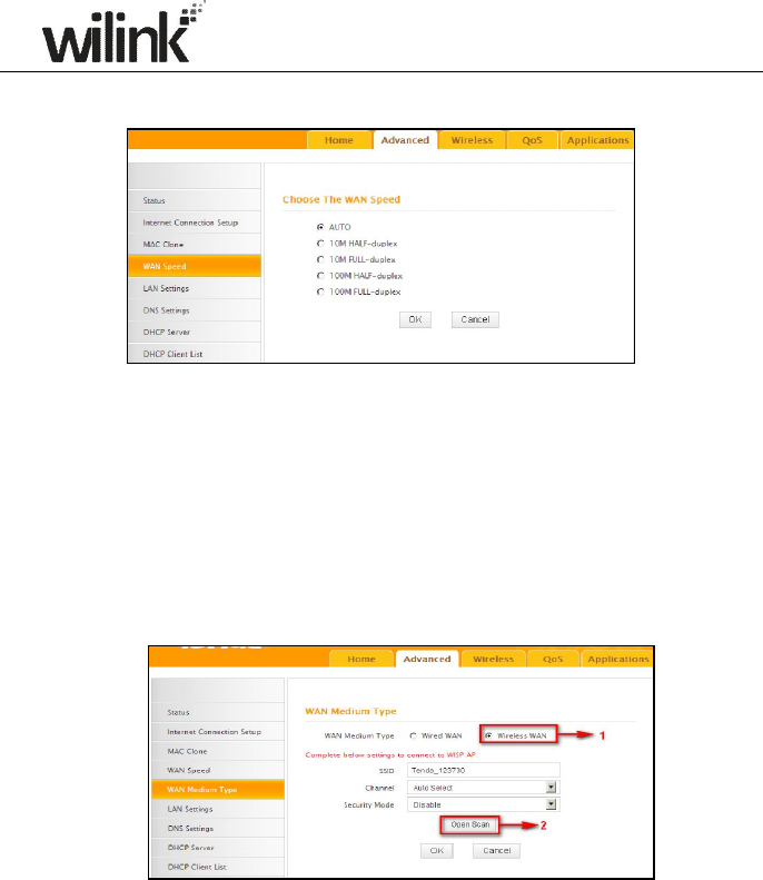
27
keep the default Auto setting to get the best speed.
3.5 WAN Medium Type
The device supports two WAN medium types: wired and wireless. Select
Wired WAN if you need to connect to your ISP via an Ethernet cable or select
Wireless WAN if you directly connect to your WISP wirelessly. The default
WAN Medium Type is Wired WAN, so no settings are required here if you
connect to your ISP via an Ethernet cable. If you connect to your WISP
wirelessly, do as follows:
1. Select Wireless WAN and enable the scan feature.
2. Select the wireless network you wish to connect, say, Wilink_office,
and click OK. Then close scan.
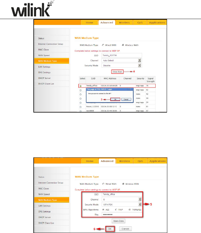
28
3. 1). Verify that SSID and channel on this page are exactly the same as
they are on the uplink wireless network you just selected.
2). Configure the same security mode, security key, cipher type (or WPA
Algorithm) as they are on the uplink wireless network you just
selected. Click OK.
1. WAN Medium Type: Select the WAN medium type you are going to
use.
2. Open Scan (or Scan): Click to search for available wireless networks
in the area and select the one you wish to connect.
3. SSID: The wireless network name of the uplink wireless device.
4. Channel: The channel used by the uplink wireless device.
5. Security Mode: The security mode used by the uplink wireless device.
6. WPA Algorithms (or Cipher Type): The WPA Algorithm (or Cipher
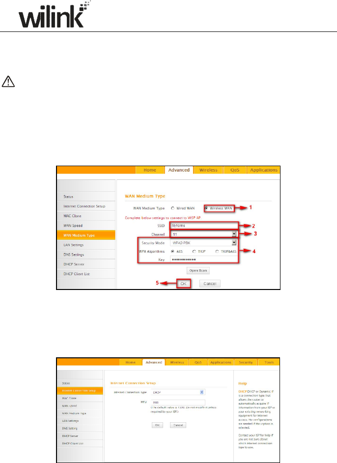
29
Type) used by the uplink wireless device.
7. Key (or Security Key): The security key used by the uplink wireless
device.
8. OK: Click this button and the router will restart to save your settings.
Note: If you change the device’s LAN IP address, you must use the new
one to log on to the web-based configuration utility.
For example:
If SSID, security mode, cipher type (WPA Algorithm), security key and
channel your WISP AP are respectively Myhome, WPA2-PSK,AES,
Wilink_router and 11, then simply enter them in corresponding fields as
seen below.
Or you can use the Open Scan (or Scan) option to have the SSID and
channel of the uplink wireless device automatically copied to this page.
When you finish all these settings, go to Advanced-> Internet
Connection Setup and select a proper Internet connection type (If your
ISP is using a DHCP connection, simply select DHCP).
30
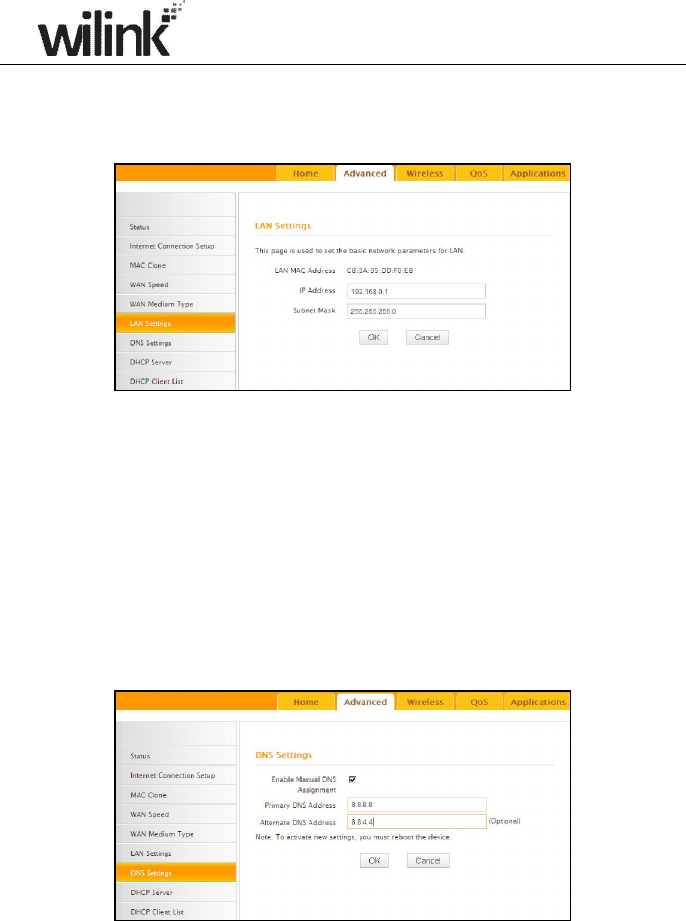
3.6 LAN Settings
Click Advanced -> LAN Settings to enter the screen below.
1. LAN MAC Address: Displays device's LAN MAC address, which is NOT
changeable.
2. IP Address: Device's LAN IP address. The default is 192.168.0.1. You
can change it according to your need.
3. Subnet Mask: Device’s LAN subnet mask, 255.255.255.0 by default.
4. OK: Click to save your settings.
3.7 DNS Settings
DNS is short for Domain Name System or Domain Name Service.
1. Enable Manual DNS Assignment: Check to activate DNS settings.
2. Primary DNS Server:Enter the primary DNS address provided by
31
your IPS.
3. Alternate DNS Server:Enter the other DNS address if your ISP
provides 2 such addresses (optional).
4. OK: Click to save your settings.
Note:
1. Web pages are not able to open if DNS server addresses are entered
incorrectly.
2. Do remember to restart the device to activate new settings when you
finish all settings.
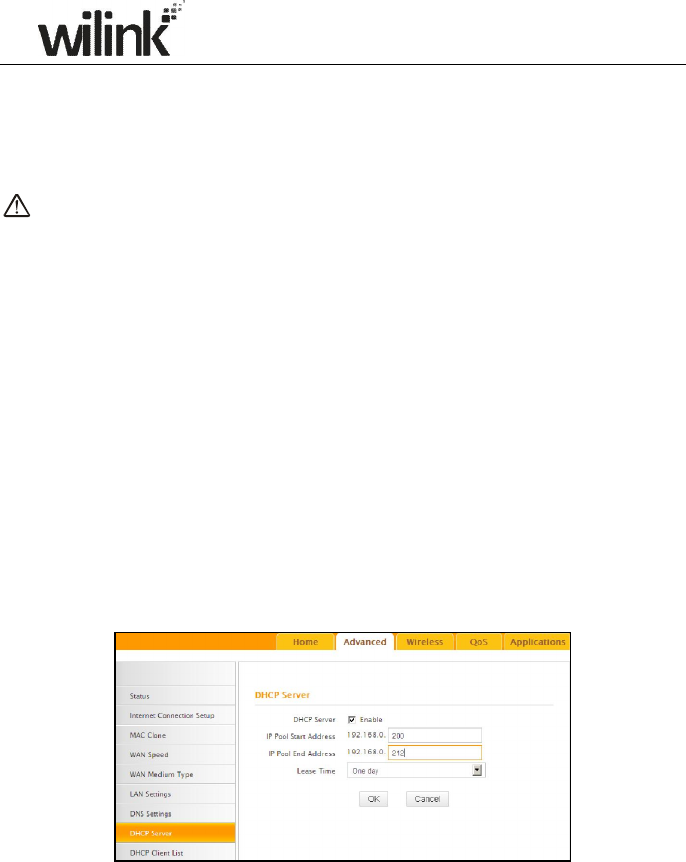
3.8 DHCP
The Dynamic Host Configuration Protocol (DHCP) is an automatic
configuration protocol used on IP networks. If you enable the built-in DHCP
server on the device, it will automatically configure the TCP/IP settings for all
your LAN computers (including IP address, subnet mask, gateway and DNS
etc), eliminating the need of manual intervention. Just be sure to set all
computers on your LAN to be DHCP clients by selecting "Obtain an IP
Address Automatically" respectively on each such PC. When turned on,
these PCs will automatically load IP information from the DHCP server. (This
feature is enabled by default. Do NOT disable it unless necessary)
3.9 DHCP Client List
DHCP Client List displays information of devices that have obtained IP
addresses from the device’s DHCP Server. If you would like some devices on
your network to always get the same IP addresses, you can manually add a
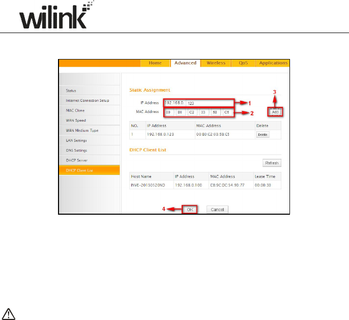
32
static DHCP reservation entry for each such device.
1. IP Address: Enter the IP address for static DHCP reservation.
2. MAC Address: Enter the MAC address of a computer to always receive
the same IP address (the IP you just specified).
3. Add: Click to add the entry to the MAC address reservation list.
4. OK: Click to save your settings.
Note:
If the IP address you have reserved for your PC is currently used by another
client, then you will not be able to obtain a new IP address from the device's
DHCP server, instead, you must manually specify a different IP address for
your PC to access Internet.
33
Chapter 4 Wireless Settings
4.1 Wireless Basic Settings
Here you can expand your wireless coverage with the following modes:
Wireless AP (default mode) and WDS.
1. Wireless Access Point (AP): Select this mode if you want to convert
an existing wired network to a wireless network so as to extend Internet
access to wireless clients.
2. WDS Bridge Mode: wireless distribution system (WDS) is a system
enabling the wireless interconnection of access points in an IEEE 802.11
network. It allows a wireless network to be expanded using multiple
access points without the traditional requirement for a wired backbone
to link them. Select this mode if you want to extend an existing wireless
network. The two modes are described as below:
4.1.1 Wireless AP Mode
1. SSID: This is the public name of your wireless network. The default is
Wilink_XXXXXX. XXXXXX is the last six characters in the device's MAC
address. It is recommended that you change it for better security and
identification.
2. Channel: Select a channel that is the least used by neighboring
networks from the drop-down list or Auto. Channels 1, 6 and 11 are
recommended.
34
3. OK: Click to save your settings.
Note:
1. It is advisable to keep other items unchanged from factory default
settings. For more details of other features, see Appendix 1.
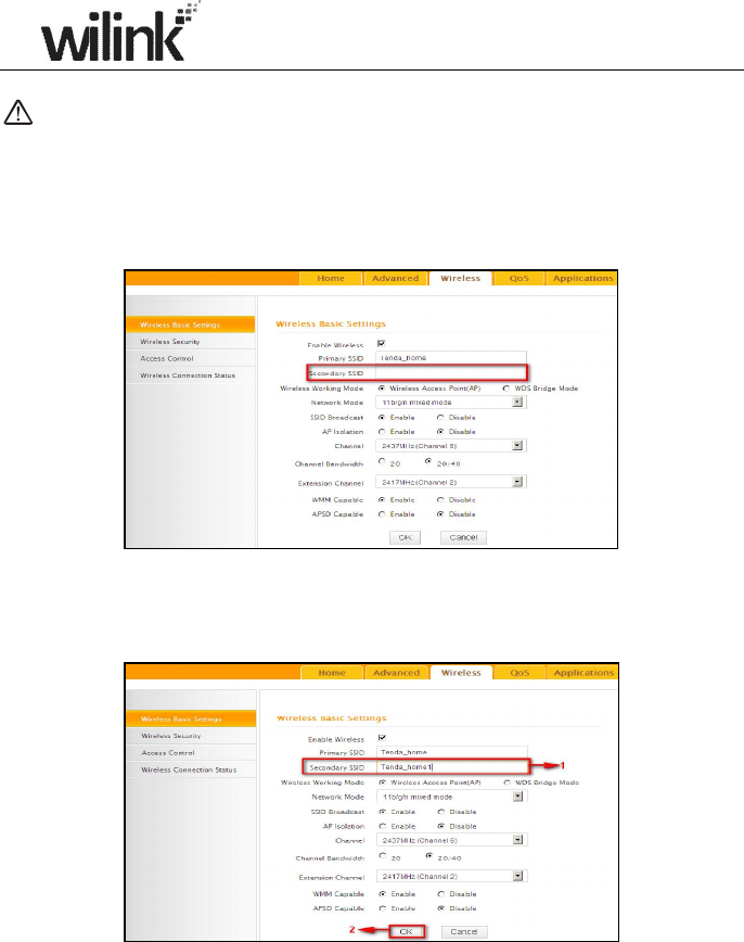
2. The device supports two SSIDs: primary SSID and secondary SSID. The
secondary SSID is optional, left blank and disabled by default.
3. To enable the secondary SSID, simply specify a SSID in the field and
click OK.
4. Instructions to configure the primary SSID also apply to the secondary
SSID. The primary SSID is used below to illustrate all wireless related
features.
35
4.1.2 WDS Bridge Mode
WDS Bridge Mode: wireless distribution system (WDS) is a system enabling
the wireless interconnection of access points in an IEEE 802.11 network. It
allows a wireless network to be expanded using multiple access points
without the traditional requirement for a wired backbone to link them. Note:
The Access Points you select MUST support WDS.
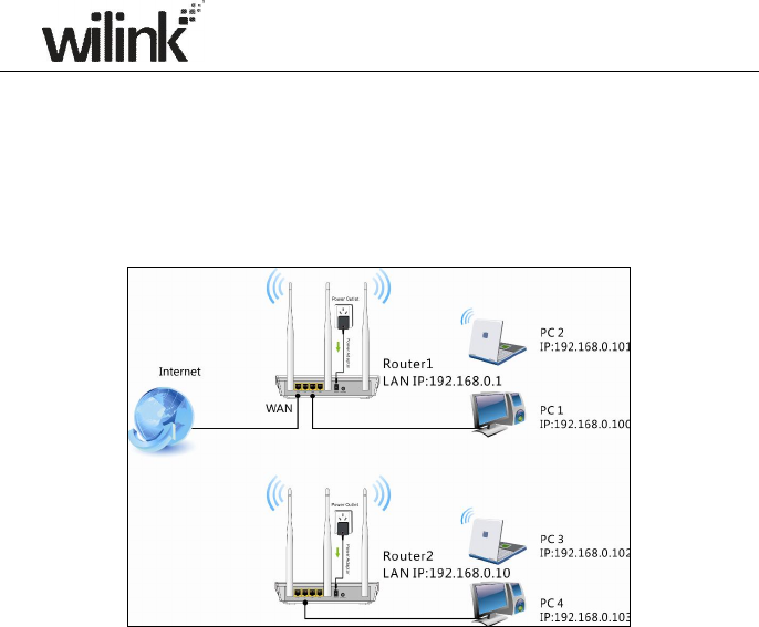
For example:
As seen in the figure above, PC1 and PC2 access Internet via a wireless
connection to Router 1. While PC3 and PC4 are too far to directly connect to
Router 1 for Internet access. Now you can use the WDS bridge feature to let
PC3 and PC4 access Internet.
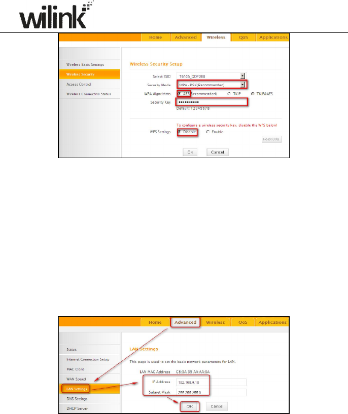
Before you get started:
1. View and note down the wireless security settings: security mode, cipher
type, security key, etc. on Router 1.
36
2. Verify that DHCP server is enabled on Router 1.
3. Set the LAN IP address of Router 2 to a different address yet on the same
net segment as Router 1.
As shown below:
Router 1:
LAN IP: 192.168.0.1;
Subnet Mask: 255.255.255.0;
Router 2:
LAN IP:192.168.0.10;
Subnet Mask: 255.255.255.0;
Then do as follows:
1. Configure Router 2:
1) Wireless Working Mode: Select WDS Bridge Mode.
2) Click Open Scan (or Scan) to search for Router 1.