TEKTELIC Communications orporated T0004437 Wireless I/F between LoRa nodes and network server User Manual 2150 RRH SDS
TEKTELIC Communications Incorporated Wireless I/F between LoRa nodes and network server 2150 RRH SDS
User Manual

TEKTELIC COMMUNICATIONS INC.
Document type: User Manual
Document number: T0004906
Document version: 1.4
Document Status: Approved
Product name: Pearl Gateway
Product codes: T0004437, T0004438, T0004372
TEKTELIC Communications Inc.
7657 10th Street NE
Calgary, AB, Canada T2E 8X2
Phone: (403) 338-6900
© 2017 TEKTELIC Communications Inc., All rights reserved.
All products, names and services are trademarks and registered trademarks of their respective companies.
Disclaimer:
Material contained in this document is subject to change without notice. The material herein is solely for
information purposes and does not represent a commitment by TEKTELIC or its representatives. TEKTELIC has
prepared the information contained in this document solely for use by its employees, agents, and customers.
Dissemination of this information and/or concepts to other parties is prohibited without the prior written consent
of TEKTELIC. In no event will TEKTELIC be liable for any incidental or consequential damage in connection with the
furnishing, performance or use of this material.
TEKTELIC reserves the right to revise this publication in accordance with formal change control procedures defined
by TEKTELIC.

Pearl Gateway User Manual T0004906 Version 1.4
TEKTELIC Communications Inc. Confidential Page 2 of 52
Revision History
Version
Date
Status
Editor
Comments
1.4
August 13,
2017
Approved T. Danshin
Added minimum separation to antenna for
mobile gateway.
1.3
August 3,
2017
Approved T. Danshin
Added additional text relating to antennas before
Table 4-8
1.2
August 2,
2017
Approved T. Danshin
Added MPE separation information for fixed
gateway
1.1 July 31, 2017 Approved T. Danshin
Clarifications for EMC filing: antenna
specifications
1.0 July 28, 2017 Approved S. Morrison
Changed document number, type and status for
formal release as approved version 1.0
0.4 June 23, 2017 Draft T. Danshin
Corrected FCC classification – removed
references to Hybrid System. Updated maximum
Tx power to 28dBm from 30dBm (in both English
and French sections of the document)
0.3 June 19, 2017 Draft S. Morrison
Corrected Fixed GW TTU output connector type
and Mobile GW 5V antenna output
0.2
June 16, 2017
Draft
S. Morrison
Updates to clarify mounting procedure
0.1
June 07, 2017
Draft
S. Morrison
Initial release
Pearl Gateway User Manual T0004906 Version 1.4
TEKTELIC Communications Inc. Confidential Page 3 of 52
Table of Contents
1 Product Description ................................................................................................................. 5
1.1 Introduction...................................................................................................................... 5
1.2 Overview .......................................................................................................................... 5
1.3 External Interfaces ........................................................................................................... 7
1.4 Specifications.................................................................................................................. 12
2 Installation ............................................................................................................................. 15
2.1 Safety Precautions .......................................................................................................... 15
2.2 Unpacking and Inspection .............................................................................................. 16
2.3 Required Equipment for Installation .............................................................................. 16
2.4 Pearl Gateway Mounting ............................................................................................... 16
2.5 Pearl TTU Mounting ....................................................................................................... 18
2.6 Ground Cable Installation .............................................................................................. 21
2.7 DC Power Cable Installation ........................................................................................... 24
2.8 RF Cable Installation ....................................................................................................... 26
3 Radio Compliance Statements .............................................................................................. 27
4 Description du produit........................................................................................................... 29
4.1 Introduction.................................................................................................................... 29
4.2 Overview ........................................................................................................................ 29
4.3 Interfaces Externes ......................................................................................................... 31
4.4 Specifications.................................................................................................................. 37
5 Installation ............................................................................................................................. 40
5.1 Précautions de sécurité .................................................................................................. 40
5.2 Déballage et inspection .................................................................................................. 41
5.3 Équipement requis pour l'installation ............................................................................ 41
5.4 Montage Pearl Gateway ................................................................................................. 41
5.5 Montage Pearl TTU......................................................................................................... 43
5.6 Installation par câble à la terre ...................................................................................... 46
5.7 Installation du câble d'alimentation CC ......................................................................... 49
Pearl Gateway User Manual T0004906 Version 1.4
TEKTELIC Communications Inc. Confidential Page 4 of 52
5.8 Installation du câble RF .................................................................................................. 51
6 Déclarations de conformité radio .......................................................................................... 52

Pearl Gateway User Manual T0004906 Version 1.4
TEKTELIC Communications Inc. Confidential Page 5 of 52
1 Product Description
1.1 Introduction
This User Guide covers two systems. One system is referred to as the Mobile Gateway which is
comprised of a single module while the second system is referred to as the Fixed Gateway
which is comprised of two modules, the Gateway Module and the Tower Top Unit (TTU)
module. As used within this document, unless otherwise qualified, the term “Gateway” will
refer to the Gateway system which includes the Gateway module, the TTU in the case of the
fixed Gateway, and any accessories such as cables and antennas, etc. Reference to individual
components will generally use the qualifying term “module”.
1.2 Overview
The Pearl Gateway is a wireless base station which operates using LoRa or FSK modulation in
the North American ISM band of 902 MHz – 928 MHz with TDD operation across the entire
band. LoRa is a long range, low power wireless standard for Internet of Things (IoT) application
(https://www.lora-alliance.org/). The FSK modulation is customer proprietary. The Gateway is
designed to be compliant with FCC Part 15.247 as either a frequency hopping spreads spectrum
(FHSS) or Digital Transmission (DTS) System. The module has a single transmitter capable of
approximately +28 dBm maximum for the fixed gateway (conducted at the TTU antenna port)
and about +20 dBm at the mobile gateway antenna port.
Table 1-1 lists the Pearl system hardware.
Table 1-1: Pearl Gateway Models
Product Code
Description
T0004437
Pearl Mobile Gateway Module
T0004438
Pearl Fixed Gateway Module
T0004372
Pearl Tower Top Unit
The Fixed Gateway is designed to operate always with the Tower Top Unit (TTU) which also
contains an LNA and as well amplifies the RF transmit signal. The TTU and antenna LNA are
powered from the Gateway which injects a bias supply voltage onto the RF antenna feed center
conductor. The Gateway RF antenna feed is protected against overload conditions and short
circuit conditions with an internal auto-resetting protection circuit.
Both Gateways support an active GPS antenna which is powered through the GPS antenna feed
from the Gateway. The GPS antenna feed is protected against overload conditions and short
circuit conditions with an internal auto-resetting protection circuit.
Pearl Gateway User Manual T0004906 Version 1.4
TEKTELIC Communications Inc. Confidential Page 6 of 52
Both Gateways contain a number of ports for data management including USB and Ethernet.
The Fixed Gateway also contains binary alarm inputs for site management.
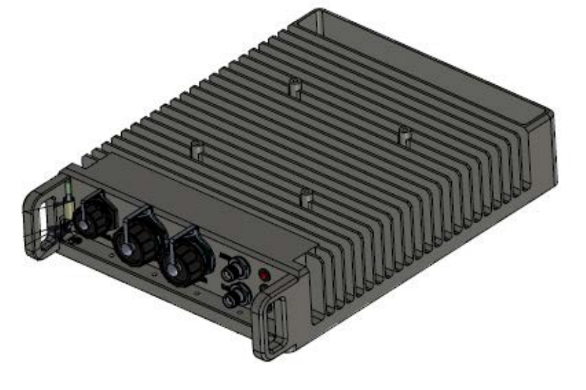
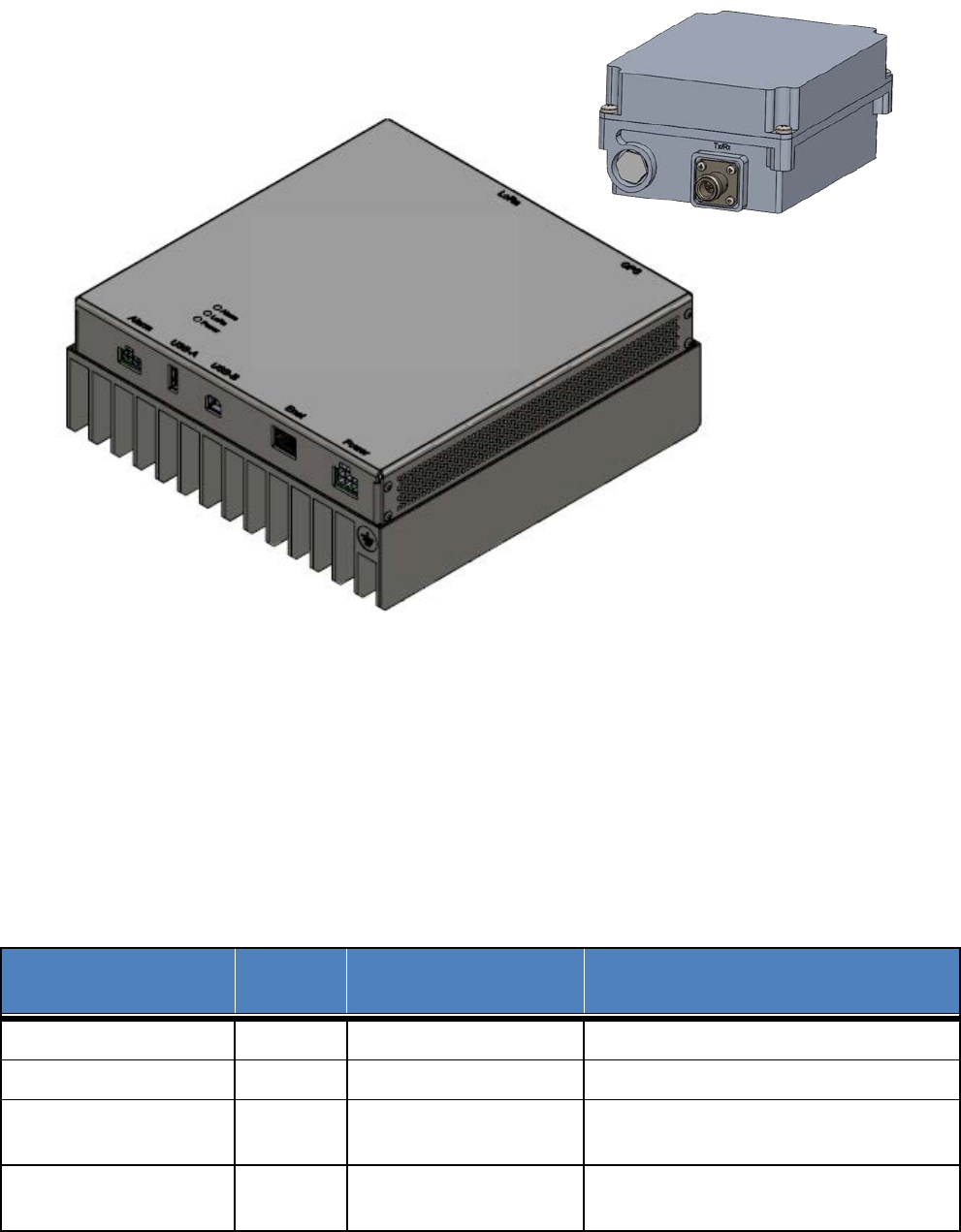
Figure 1 illustrates Mobile Gateway while Figure 2 illustrates the Fixed Gateway.
Figure 1: Pearl Mobile Gateway
Pearl Gateway User Manual T0004906 Version 1.4
TEKTELIC Communications Inc. Confidential Page 7 of 52
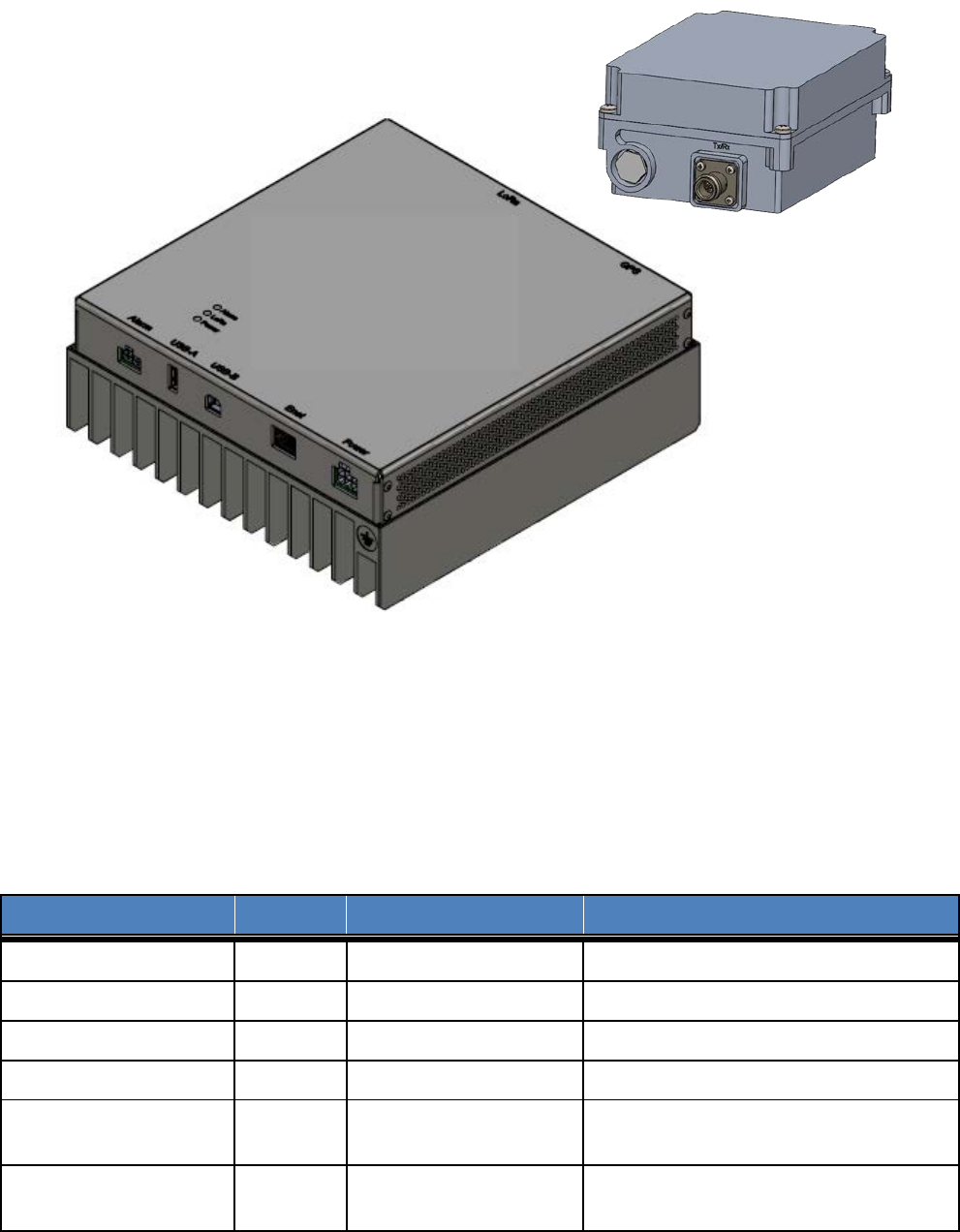
Figure 2: Pearl Fixed Gateway
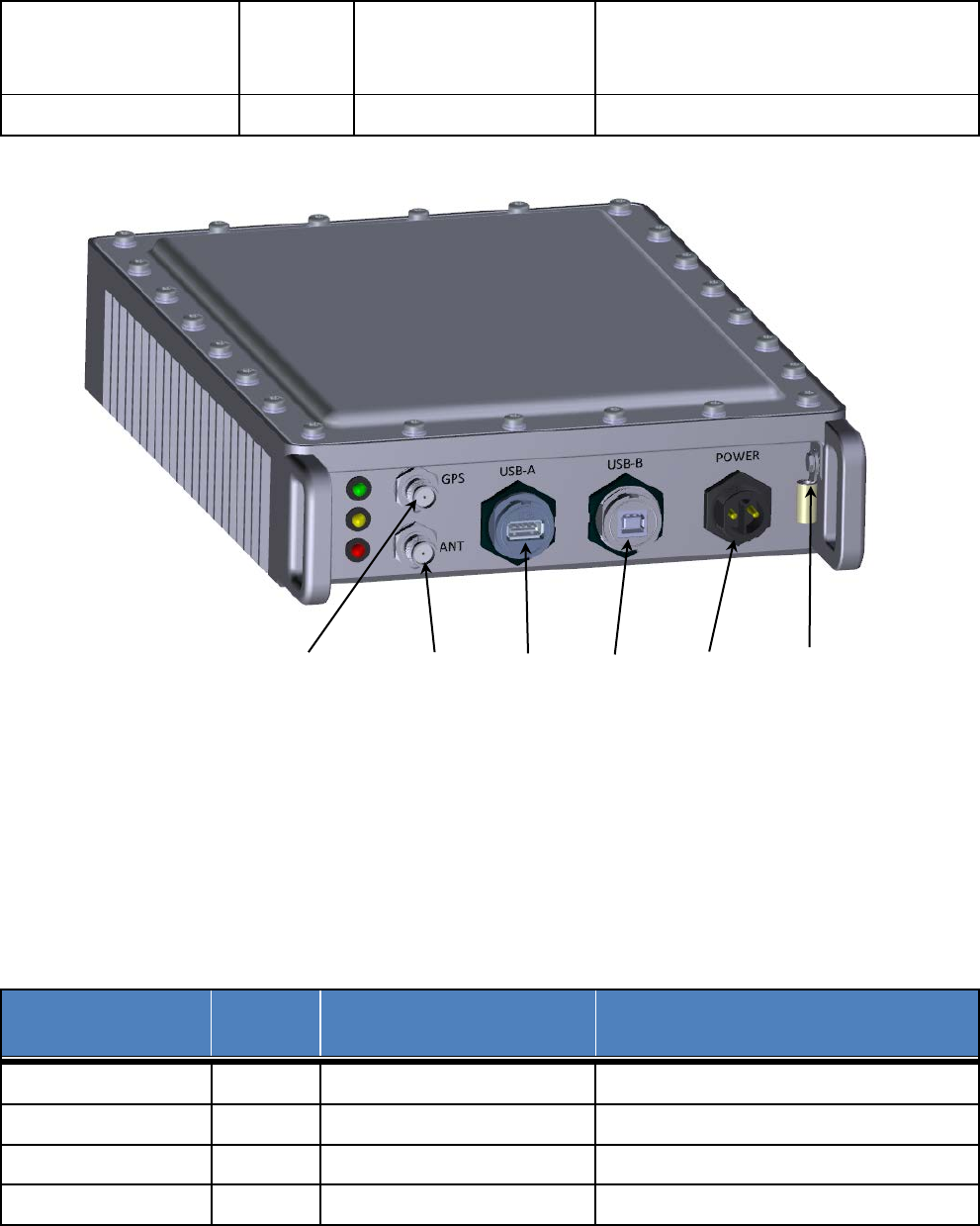
1.3 External Interfaces
The Mobile Gateway Module interface connectors are listed in Table 1-2 and illustrated in
Figure 3.
Table 1-2: Pearl Mobile Gateway Module Interface Connectors
Interface
Location
Connector Type
Mating Connector
ISM Antenna Port
Front
TNC jack
Industry standard TNC plug
GPS Antenna Port
Front
TNC jack
Industry standard TNC plug
USB-A
Front
USB type A receptacle
Industry standard USB type A plug
USB-B
Front
USB type B receptacle
Industry standard USB type B plug
DC Power Front
2-pin threaded circular
plastic connector ( CPC)
Shenzhen Chogori Technology Co., Ltd.
p/n 33000111-02 or equivalent
Chassis (Earth) Ground Front Screw with lug
Industry standard single hole lug for #8-
32 screw
TTU
Module
Fixed Gateway
Module
Pearl Gateway User Manual T0004906 Version 1.4
TEKTELIC Communications Inc. Confidential Page 8 of 52
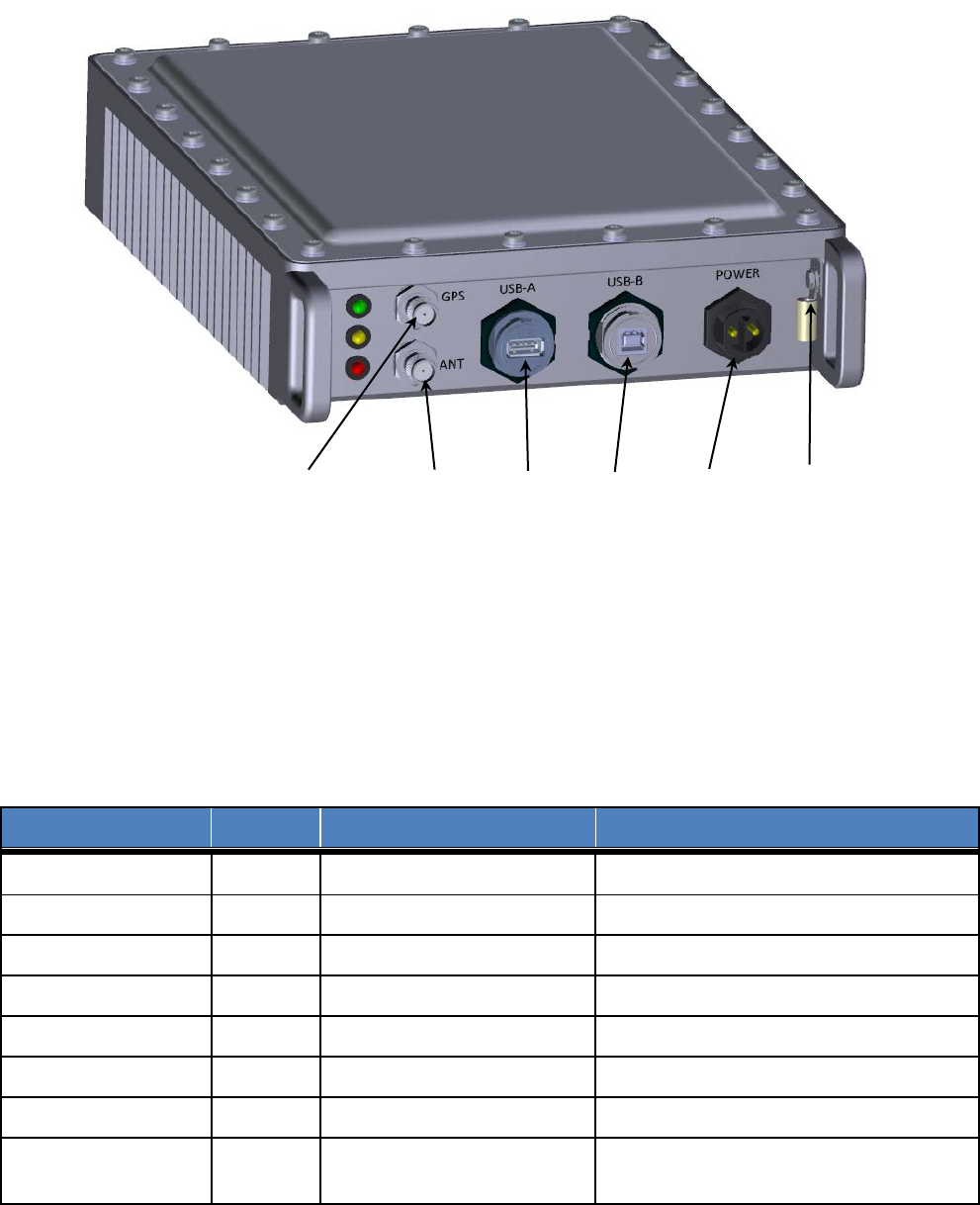
Figure 3: Pearl Mobile Gateway Module Interconnect
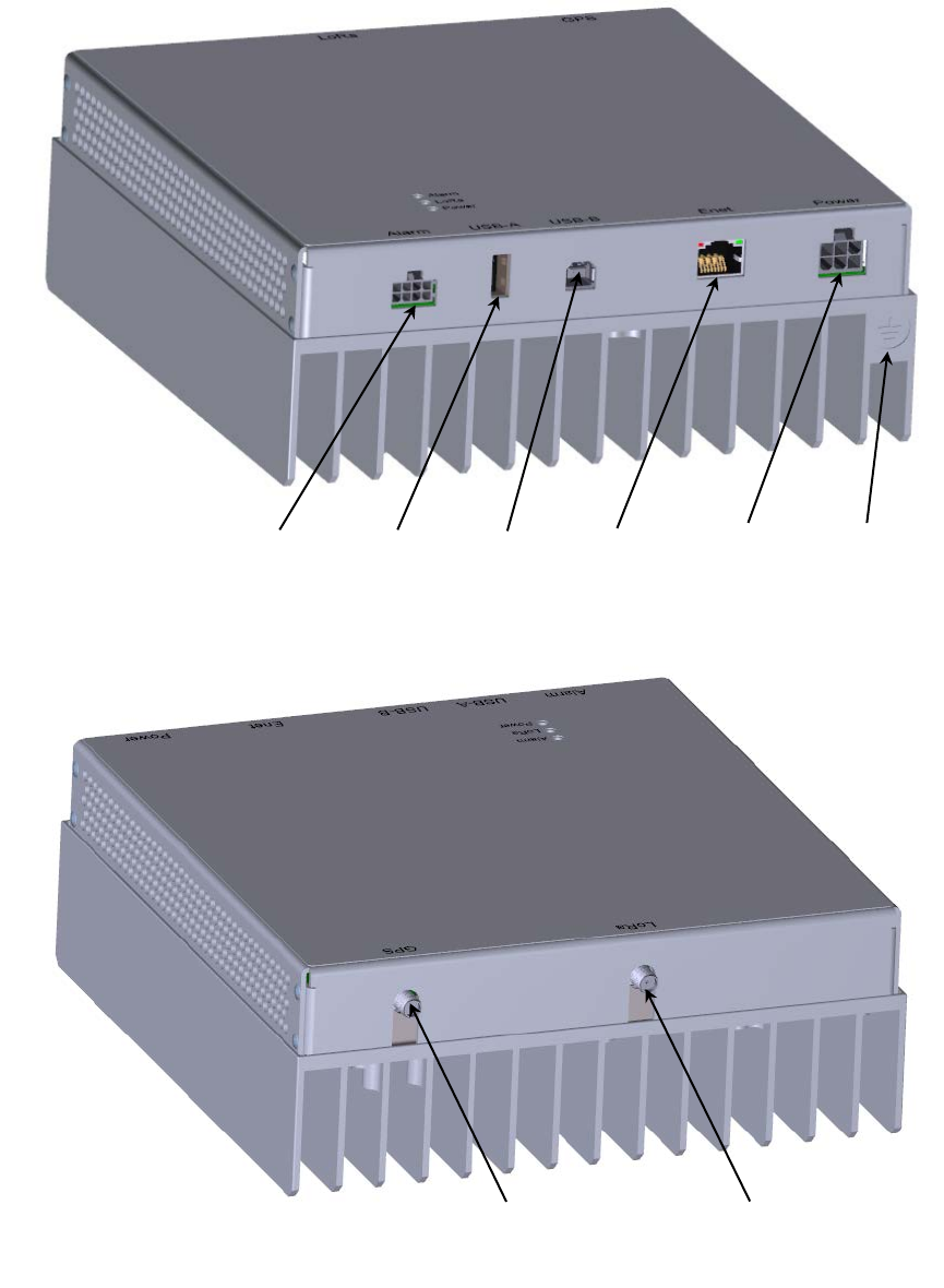
The Fixed Gateway Module interface connectors are listed in Table 1-3 and illustrated in Figure
4.
Table 1-3: Pearl Fixed Gateway Module Interface Connectors
Interface
Location
Connector Type
Mating Connector
TTU interface Port
Back
SMA jack
Industry standard SMA plug
GPS Antenna Port
Back
SMA jack
Industry standard SMA plug
DC Power & alarms
Front
Molex Mini-fit 2x3 header
Molex Mini-fit 2x3 plug
Site Alarms
Front
Molex Mini-fit 2x4 header
Molex Mini-fit 2x4 plug
USB-A
Front
USB type A receptacle
Industry standard USB type A plug
USB-B
Front
USB type B receptacle
Industry standard USB type B plug
Ethernet
Front
RJ-45 socket
Industry standard RJ-45 plug
Chassis (Earth)
Ground
Front Screw with lug
Industry standard single hole lug for #8-
32 screw
USB-B
DC power
USB-A
ISM antenna
Chassis
ground
GPS antenna

Pearl Gateway User Manual T0004906 Version 1.4
TEKTELIC Communications Inc. Confidential Page 9 of 52
Figure 4: Pearl Fixed Gateway Module Interconnect
Site alarms
USB-B
DC power
& alarms
Ethernet
USB-A
GPS antenna
ISM antenna
Chassis
ground
Front Bulkhead
Rear Bulkhead

Pearl Gateway User Manual T0004906 Version 1.4
TEKTELIC Communications Inc. Confidential Page 10 of 52
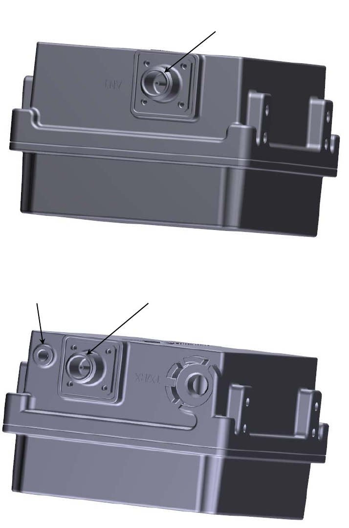
The TTU Module interface connectors are listed in Table 1-4 and illustrated in Figure 5.
Table 1-4: Pearl TTU Module Interface Connectors
Interface
Location
Connector Type
Mating Connector
ISM RF Antenna Port
Top
N-type female
Industry standard N-type male
Gateway module
interface Port Bottom N-type female Industry standard N-type male
Chassis (Earth)
Ground
Bottom Screw with lug
Industry standard single hole lug for #8-
32 screw

Pearl Gateway User Manual T0004906 Version 1.4
TEKTELIC Communications Inc. Confidential Page 11 of 52
Figure 5: Pearl TTU Module Interconnect
Fixed Gateway
Module interface
Chassis
ground
IMS antenna
port
Top
Bottom

Pearl Gateway User Manual T0004906 Version 1.4
TEKTELIC Communications Inc. Confidential Page 12 of 52
1.4 Specifications
The Pearl Mobile Gateway Module specifications are listed in Table 1-5.
Table 1-5: Pearl Mobile Gateway Module Specifications
Attribute
Specification
Dimensions
218.8mm (8.6”) wide x 72mm (2.8”) deep x 303.8mm (12.0”) tall
Weight
3.15 kg (6.95 lbs)
Operating Temperature
-40°C to 60°C (-40°F to 140°F) ambient at sea level Including solar loading
Relative Humidity
10% to 100%
Operating Altitude
Maximum 2,000 m (6,560 ft)
DC Power Input
12V DC nominal
10V to 15V DC operating range
+/-16V DC no damage
30W maximum
Maximum 20A input overcurrent protection.
ISM antenna output
power
5V DC, 300mA maximum
GPS antenna output
power
5V DC, 50mA maximum
Weather Tightness
Indoor product
Regulatory Compliance
CSA/UL 60950-1
FCC Pt. 15 Class B
The Pearl Fixed Gateway Module specifications are listed in Table 1-6.
Table 1-6: Pearl Fixed Gateway Module Specifications
Attribute
Specification
Dimensions
189.4mm (7.5”) wide x 77mm (3.0”) deep x 197.8mm (7.8”) tall
Weight
1.71 kg (3.76 lbs)
Operating Temperature
-40°C to 70°C (-40°F to 158°F) ambient at sea level Including solar loading
Relative Humidity
10% to 100%
Operating Altitude
Maximum 2,000 m (6,560 ft)
DC Power Input
12V DC nominal
10V to 15V DC operating range
+/-16V DC no damage

Pearl Gateway User Manual T0004906 Version 1.4
TEKTELIC Communications Inc. Confidential Page 13 of 52
40W maximum
Maximum 20A input overcurrent protection.
TTU port output power
12V DC, 1.5A maximum
GPS antenna output
power
5V DC, 50mA maximum
Weather Tightness
Indoor product
Regulatory Compliance
CSA/UL 60950-1
FCC Pt. 15 Class B
The Pearl TTU Module specifications are listed in Table 1-7.
Table 1-7: Pearl TTU Module Specifications
Attribute
Specification
Dimensions
222.2mm (8.7”) wide x 101mm (4.0”) deep x 287.3mm (11.3”) tall
Weight
2.1 kg (4.6 lbs)
Operating Temperature
-40°C to 65°C (-40°F to 149°F) at sea level Including solar loading.
Relative Humidity
10% to 100%
Operating Altitude
Maximum 3,048 m (10,000 ft)
Surge protection
20kV, 1.2/50us combination waveform
Weather Tightness
IP67
Regulatory Compliance
CSA/UL 60950-1 & & CSA/UL 60950-22
FCC Pt. 15 Class B

Pearl Gateway User Manual T0004906 Version 1.4
TEKTELIC Communications Inc. Confidential Page 14 of 52
This radio transmitter (Mobile Gateway IC: 22504-T0004437, Fixed Gateway IC: 22504-
T0004438) has been approved by Industry Canada to operate with the antenna types listed
below with the maximum permissible gain indicated. Antenna types not included in this list,
having a gain greater than the maximum gain indicated for that type, are strictly prohibited for
use with this device.
The specified ISM antennas are listed in Table 1-8.
Table 1-8 ISM Antennas
Gateway
Type IC: Number
Antenna
Vendor Model Number Gain (dBi)
Mobile
Gateway IC: 22504-T0004437 PCTel BMUF9115 5
Fixed
Gateway +
TTU
IC: 22504-T0004438 L-Com HG908U-PRO 8
Fixed
Gateway +
TTU
IC: 22504-T0004438 L-Com HGV906U 6
Pearl Gateway User Manual T0004906 Version 1.4
TEKTELIC Communications Inc. Confidential Page 15 of 52
2 Installation
2.1 Safety Precautions
• Installation, operation, and maintenance of the Pearl Gateway must only be performed by a
trained person who is aware of all hazards involved.
• The Pearl Gateway must be installed in a restricted access location (such that touching of
the Gateway by untrained persons is not likely).
• The Pearl Gateway may become hot to the touch during normal operation at elevated
ambient temperatures. The surface temperature of the enclosure may reach 90°C.
• The Pearl Gateway has no internal field serviceable parts. The Gateway module must only
be opened by an approved service center.
• All installation practices must be in accordance with local and national electrical codes.
• Do not work on the system during periods of lightning activity.
• The Pearl Gateway is considered permanently connected equipment. The Protective Earth
Ground connection to chassis is always required.
• Ensure the Pearl Gateway Protective Earth Ground connection is properly terminated prior
to the connection of any other interfaces.
• The Pearl Gateway TTU contains primary lightning surge suppression on the RF ports. The
primary lightning protectors have the ability to shunt lightning energy to earth ground
which includes the chassis. Ensure that the Protective Earth Ground connection is always in
place.
• Ensure that the Pearl Gateway including the TTU and its antennas and supporting structures
are properly secured to eliminate any physical hazard to people or property. The Gateway
including the TTU must be securely mounted according to the mounting instructions prior to
any cable connection and operation.
• The Pearl Gateway does not contain a power supply disconnection device; a readily
accessible disconnection device must be incorporated external to the Gateway.
• The Pearl Gateway shall be supplied through an input overcurrent protection device rated
not more than 20 A. The overcurrent protection must have the appropriate current
interrupt capacity for the power source and must be incorporated into the non-earthed
conductor(s) of the DC supply.
Pearl Gateway User Manual T0004906 Version 1.4
TEKTELIC Communications Inc. Confidential Page 16 of 52
• The DC input power positive pin must be at positive potential relative to the DC negative pin
for the Gateway to function. If the polarity is reversed, the unit will not sustain damage but
will not operate until the polarity is corrected.
• The Pearl Gateway DC power source must meet SELV requirements.
2.2 Unpacking and Inspection
The following should be considered during the unpacking of a new Pearl Gateway.
1. Inspect the shipping carton and report any significant damage to TEKTELIC.
2. Unpacking should be conducted in a clean and dry location when possible.
3. Do not discard the shipping box or foam inserts as they will be required if a unit is
returned for repair or re-configuration.
2.3 Required Equipment for Installation
The following tools are required to install the Pearl Gateway system:
1. An imperial and a metric socket with Torx set and a torque wrench.
2. Anti-oxidant compound (NO-OX-ID, Penetrox, Noalox, Ox-Gard or equivalent).
3. A small wire brush or emery cloth.
4. A clean cloth.
5. Weatherproofing tape kit for the RF connectors (Scotch Wireless Weatherproofing Kit,
WK-101 recommended).
6. Four M4 screws with locking hardware for Gateway mounting (length according to
application, see next section).
7. Four M8 screws with locking hardware for TTU mounting according to application (see
next section).
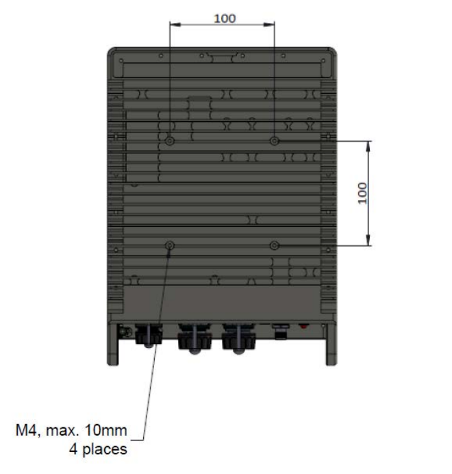
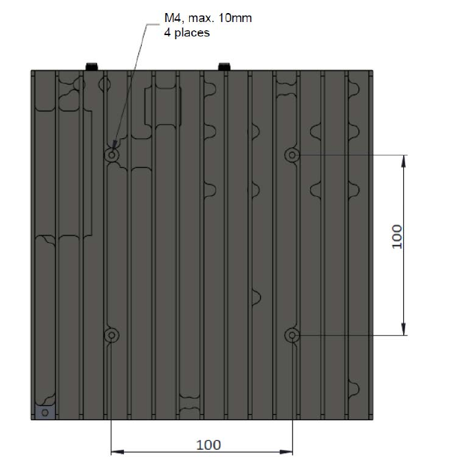
2.4 Pearl Gateway Mounting
The Pearl Gateway Modules are designed to be mounted to a flat surface using site supplied
M4 x 0.7 stainless screws with locking hardware, one at each of the four mounting points as
illustrated in Figure 6 for the Mobile Gateway Module and Figure 7 for the Fixed Gateway
Module. These four mounting screws are to pass through pre-drilled holes in the mounting
surface. The mounting drill-hole pattern is on a square as indicated in Figure 6 and Figure 7. The
dill size shall be selected for a slight clearance to M4 screws.
Mounting the Gateway module requires access to both sides of the mounting surface; this may
require two persons in cases where the mounting surface is large.

Pearl Gateway User Manual T0004906 Version 1.4
TEKTELIC Communications Inc. Confidential Page 17 of 52
The length of M4 mounting screw shall be determined according to the mounting surface
thickness. After accommodating for the locking hardware and mounting surface thicknesses,
the M4 mounting screws shall tread into the gateway chassis by at least 5 mm but not more
than 10 mm.
The Gateway Module mounting orientation is to be such that the chassis fins are vertical.
Ensure that the surface and related structure to which the Module is being mounted is secure
and able to support a dead load of at least 136 kg (300 lbs).
Ensure sufficient free space around the bulkhead connectors for access and cable ingress.
Figure 6: Pearl Mobile Gateway Module Mounting Points

Pearl Gateway User Manual T0004906 Version 1.4
TEKTELIC Communications Inc. Confidential Page 18 of 52
Figure 7: Pearl Fixed Gateway Module Mounting Points
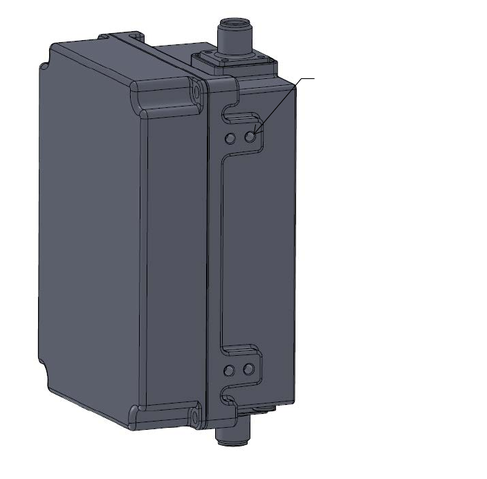
2.5 Pearl TTU Mounting
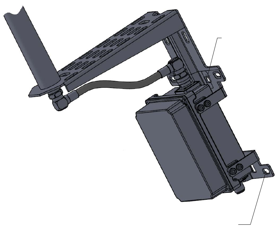
The Pearl TTU module is designed to be mounted to a flat surface or to a pole using the
supplied mounting brackets. The TTU may be mounted with two of the small brackets as
illustrated in Figure 9 or with one small bracket and one antenna bracket as illustrated in Figure
10. Each bracket shall be attached to the TTU module using four of the supplied M5 x 0.8 –
10mm stainless steel screws at the locations illustrated in Figure 8. Once the brackets are
attached to the TTU module, the module may be mounted.
To mount the TTU with bracket to a flat surface, four site supplied stainless steel M8 bolts are
required, two at each end of each bracket as illustrated in Figure 8 and Figure 9. The M8 bolts
shall be selected according to the site specific mounting surface material and shall include
locking hardware.

Pearl Gateway User Manual T0004906 Version 1.4
TEKTELIC Communications Inc. Confidential Page 19 of 52
To mount the TTU with bracket to a pole, two site supplied stainless steel pole straps are
required, one at each mounting bracket looped through the strap slots as indicated in Figure 8
and Figure 9.
The TTU mounting orientation is to be vertical with the vent plug pointing down to earth.
Ensure that the surface or pole and related structure to which the Module is being mounted are
secure and able to support a dead load of at least 136 kg (300 lbs).
Ensure sufficient free space around the bulkhead connectors for access and cable ingress.
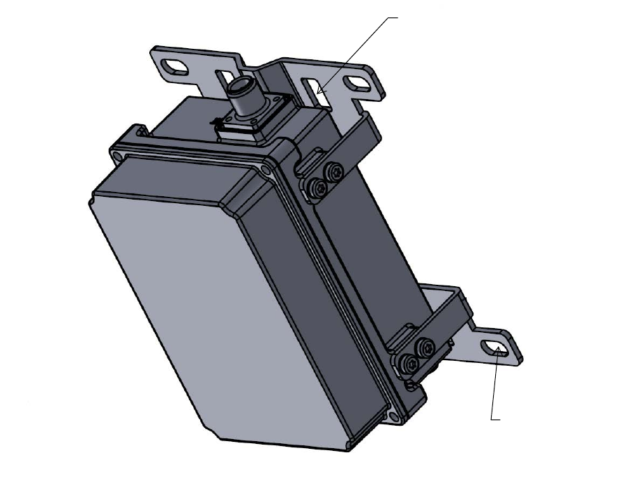
Figure 8: TTU Module Mounting Points
2
x M5 x 0.8, max. 10mm
4 places
Pearl Gateway User Manual T0004906 Version 1.4
TEKTELIC Communications Inc. Confidential Page 20 of 52
Figure 9: TTU Module Mounting with Small Brackets
Slot for pole strap
4 places
M8 screw or bolt
4 places

Pearl Gateway User Manual T0004906 Version 1.4
TEKTELIC Communications Inc. Confidential Page 21 of 52
Figure 10: TTU Module Mounting with One Small and One Antenna Bracket
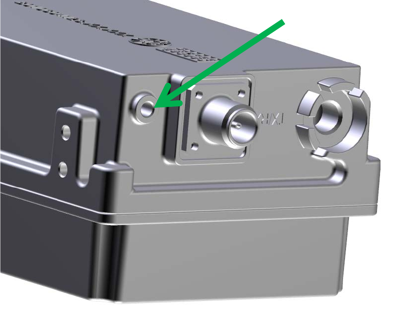
2.6 Ground Cable Installation
The Pearl Gateway is considered Permanently Connected Equipment and requires a
permanently connected Protective Earth Ground (PEG) conductor for each module. The
Protective Earth Ground connection is made through a #8-32 screw using an industry standard
single-hole lug as illustrated in Figure 6 for the Mobile Gateway Module, Figure 6 for the Fixed
Gateway Module, and Figure 6 for the TTU Module.
The recommended ground cable gauge is #10 AWG minimum.
The Pearl Gateway grounding system shall follow local and national electrical codes. The
Protective Earth Ground conductor terminated at the ground lug point is mandatory and must
M8 screw or bolt
4 places
Slot for pole strap
4 places
Pearl Gateway User Manual T0004906 Version 1.4
TEKTELIC Communications Inc. Confidential Page 22 of 52
be the first connection made to the Pearl Gateway during installation. Proper routing and
termination of this cable is key to robust EMI performance; in high susceptibility installations,
every effort shall be made to minimize ground connection impedance
The ground cable installation steps are as follows:
1. Lightly abrade the surface of the chassis grounding area (the paint free area around the
ground screw hole) with a fine wire brush or emery cloth to remove the oxide layer
which may have formed.
2. Use a clean cloth to remove any debris from this surface.
3. Immediately coat the contact surface with a thin layer of anti-oxidant compound.
4. Install the ground cable with its screw lug onto the chassis ground point using a #8-32
screw with flat and star lock washers, torqued to 2.2 Nm (20 in·lbs).
Figure 11: Pearl Mobile Gateway Module Ground Point
#8-32
Pearl Gateway User Manual T0004906 Version 1.4
TEKTELIC Communications Inc. Confidential Page 23 of 52
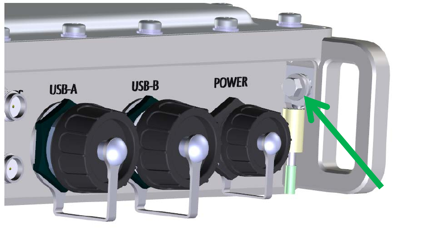
Figure 12: Pearl Fixed Gateway Module Ground Point
#8-32

Pearl Gateway User Manual T0004906 Version 1.4
TEKTELIC Communications Inc. Confidential Page 24 of 52
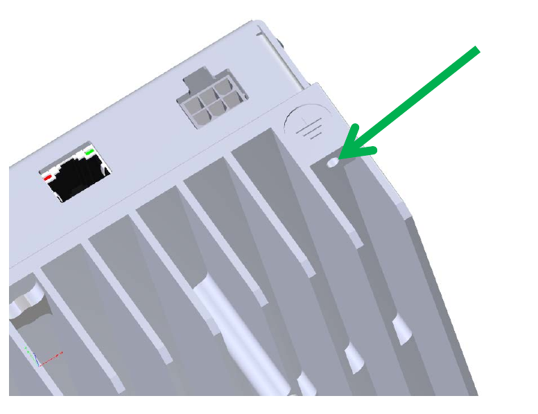
Figure 13: Pearl TTU Module Ground Point
2.7 DC Power Cable Installation
The Gateway Module DC power input is isolated from chassis (earth). One lead of the DC power
feed is normally earth referenced external to the Pearl Gateway, usually at the power source by
convention.
An input overcurrent protection device rated not more than 20 A, and with the appropriate
current interrupt capacity for the power source, must be incorporated into the non-earthed
conductor(s) of the DC supply.
DC power is supplied to the Mobile Gateway Module through a two pin circular plastic
connector (CPC). The mating CPC connector shall be as specified in Table 1-2 and shall follow
the polarity identified in Figure 14.
#8-32
Pearl Gateway User Manual T0004906 Version 1.4
TEKTELIC Communications Inc. Confidential Page 25 of 52
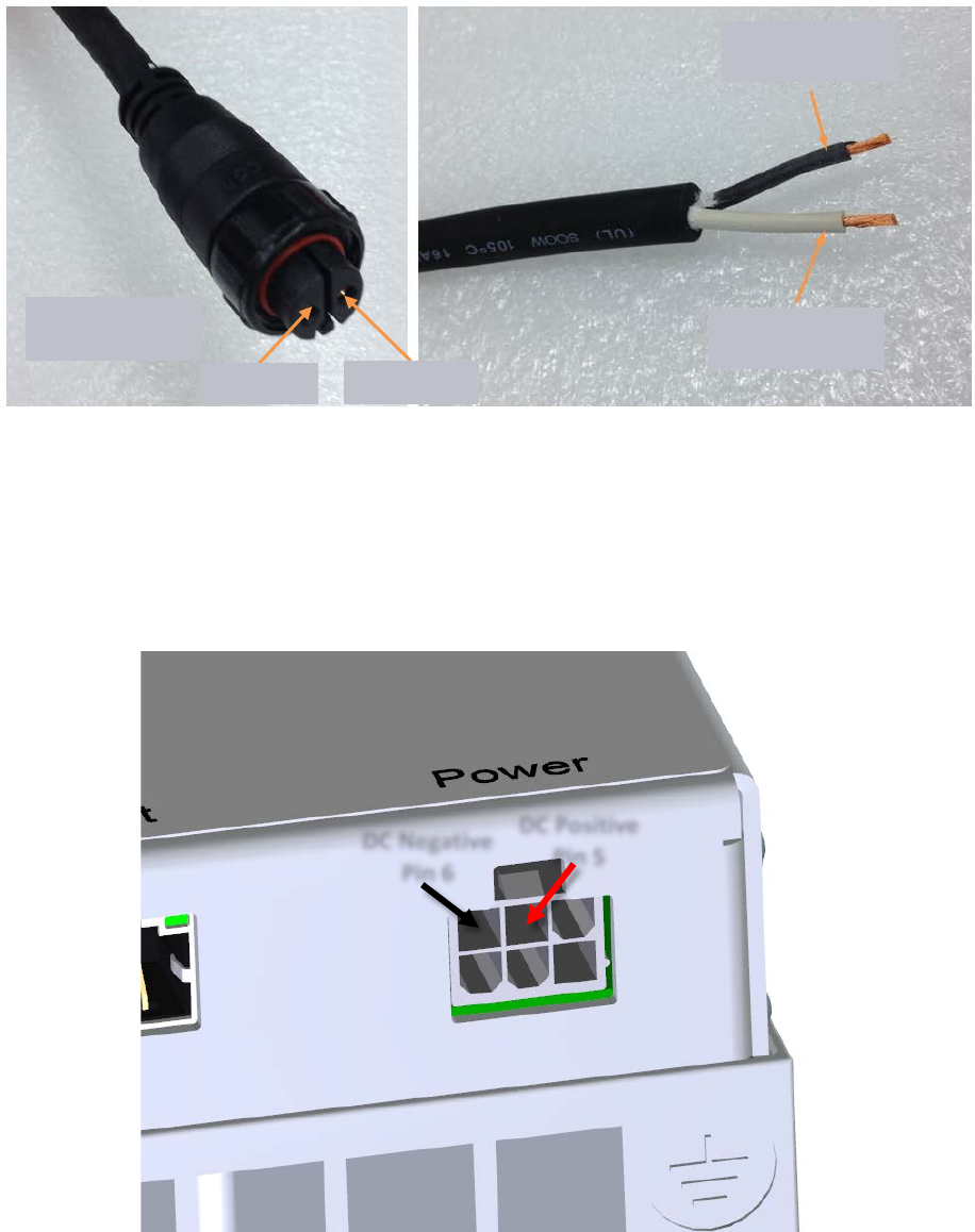
Figure 14: Mobile Gateway Module DC Power Connector Signals
DC power is supplied to the Fixed Gateway Module through two pins of a six pin Molex Mini-fit
connector. The mating connector shall be as specified in Table 1-3 and shall follow the signal
assignment identified in Figure 15.
Figure 15: Fixed Gateway Module DC Power Connector Signals
Black
DC Negative
White
DC Positive
Keyed DC Power
Connector (CPC)
DC Positive
DC Negative
DC Positive
Pin 5
DC Negative
Pin 6
Pearl Gateway User Manual T0004906 Version 1.4
TEKTELIC Communications Inc. Confidential Page 26 of 52
DC power is supplied to the TTU Module through the RF cable connection to the Fixed Gateway.
2.8 RF Cable Installation
The Gateway installation will require connection to a GPS antenna and an ISM RF antenna.
Antenna gain and type must respect the equipment specification. For the case of the fixed
gateway, transmit power configuration is not a function of antenna type. The system maximum
transmit power is configured assuming an antenna with the highest specified gain (8dBi) is
used. If the 6dBi antenna is used, the radiated power is 2dB less. The RF connector interface
to a cable is not generally water proof and must be taped to be used outdoors. TEKTELIC
recommends taping with Scotch Wireless Weatherproofing Kit, WK-101. Follow the taping
procedures outlined by the supplier of this tape system.
Pearl Gateway User Manual T0004906 Version 1.4
TEKTELIC Communications Inc. Confidential Page 27 of 52
3 Radio Compliance Statements
Federal Communications Commission
This device complies with Part 15 of the FCC Rules. Operation is subject to the following two conditions:
1. This device may not cause harmful interference, and
2. This device must accept any interference received, including interference that may cause undesired operation.
Changes or modifications not expressly approved by the party responsible for compliance could void the user’s authority to
operate the equipment
This equipment has been tested and found to comply with the limits for a Class B digital device, pursuant to Part 15 of the FCC
Rules. These limits are designed to provide reasonable protection against harmful interference in a residential installation.
This equipment generates uses and can radiate radio frequency energy and, if not installed and used in accordance with the
instructions, may cause harmful interference to radio communications. However, there is no guarantee that interference will
not occur in a particular installation. If this equipment does cause harmful interference to radio or television reception, which
can be determined by turning the equipment off and on, the user is encouraged to try to correct the interference by one of
the following measures:
• Reorient or relocate the receiving antenna.
• Increase the separation between the equipment and receiver.
• Connect the equipment into an outlet on a circuit different from that to which the receiver is connected.
• Consult the dealer or an experienced radio/TV technician for help.
Notice applicable to the Pearl Fixed Gateway only:
Maximum antenna gain is 8 dBi and omnidirectional type. Antenna with maximum gain used for this transmitter must be
installed to provide a separation distance of at least 21.4 cm (8.4 inches) from all persons. This product must be installed by
trained RF technicians.
Industry Canada
This Device complies with Industry Canada License-exempt RSS standard(s). Operation is subject to the following two
conditions:
1. This device may not cause interference, and
2. This device must accept any interference, including interference that may cause undesired operation of the device.
This radio transmitter (certification number) has been approved by Industry Canada to operate with the antenna types listed
below with the maximum permissible gain indicated. Antenna types not included in this list, having a gain greater than the
maximum gain indicated for that type, are strictly prohibited for use with this device.
The required antenna impedance is 50 ohms.
Only antenna with maximum gain of 5dBi can be used for the mobile gateway (tested). Only antenna with a maximum gain of
8dBi can be used for the fixed gateway.
Notice applicable to the Pearl Mobile Gateway only:
Antenna specified for this transmitter must be installed to provide a separation distance of at least 0.20 m from all persons.
This product must be installed by trained RF technicians.’
Pearl Gateway User Manual T0004906 Version 1.4
TEKTELIC Communications Inc. Confidential Page 28 of 52
Notice applicable to the Pearl Fixed Gateway only:
Maximum antenna gain is 8 dBi and omnidirectional type. Antenna with maximum gain used for this transmitter must be
installed to provide a separation distance of at least 0.33 m from all persons. This product must be installed by trained RF
technicians.

Pearl Gateway User Manual T0004906 Version 1.4
TEKTELIC Communications Inc. Confidential Page 29 of 52
4 Description du produit
4.1 Introduction
Ce Guide de l'utilisateur couvre deux systèmes. Un système est appelé la passerelle mobile qui
se compose d'un module unique tandis que le deuxième système est appelé la passerelle fixe
qui se compose de deux modules, le module de passerelle et le module TTU (Tower Top Unit).
Tel qu'utilisé dans ce document, sauf indication contraire, le terme «passerelle» se référera au
système Gateway qui comprend le module Gateway, le TTU dans le cas de la passerelle fixe et
tous les accessoires tels que les câbles et les antennes, etc. Les composants individuels utilisent
généralement le terme «module».
4.2 Overview
La Pearl Gateway est une station de base sans fil qui utilise la modulation LoRa ou FSK dans la
bande ISM nord-américaine de 902 MHz - 928 MHz avec une opération TDD sur l'ensemble de
la bande. LoRa est une norme sans fil à longue portée et faible puissance pour l'application
Internet of Things (IoT) (https://www.lora-alliance.org/). La modulation FSK est propriétaire du
client. La passerelle est conçue pour être conforme à la partie 15.247 de la FCC comme
système de spectre de propagation de fréquence (FHSS) ou de transmission numérique (DTS).
Le module dispose d'un seul émetteur capable d'atteindre approximativement +28 dBm
maximum pour la passerelle fixe (conduit au port de l'antenne TTU) et d'environ +20 dBm sur le
port de l'antenne de la passerelle mobile.
Le tableau 1 énumère le matériel du système Pearl.
Table 4-1: Pearl Gateway Maquette
Product Code
Description
T0004437
Pearl Mobile Gateway Module
T0004438
Pearl Fixed Gateway Module
T0004372
Pearl Tower Top Unit
La passerelle fixe est conçue pour fonctionner toujours avec le Tower Top Unit (TTU) qui
contient également un LNA et amplifie le signal d'émission RF. Le TTU et l'antenne LNA sont
alimentés à partir de la passerelle qui injecte une tension d'alimentation de polarisation sur le
conducteur central d'alimentation de l'antenne RF. L'alimentation de l'antenne RF Gateway est
protégée contre les conditions de surcharge et les conditions de court-circuit avec un circuit de
protection interne auto-réinitialisation.

Pearl Gateway User Manual T0004906 Version 1.4
TEKTELIC Communications Inc. Confidential Page 30 of 52
Les deux passerelles prennent en charge une antenne GPS active alimentée par l'alimentation
de l'antenne GPS depuis la passerelle. L'alimentation de l'antenne GPS est protégée contre les
conditions de surcharge et les conditions de court-circuit avec un circuit de protection auto-
réinitialisation interne.
Les deux passerelles contiennent un certain nombre de ports pour la gestion des données, y
compris l'USB et Ethernet.
La passerelle fixe contient également des entrées d'alarme binaires pour la gestion du site.
La figure 1 illustre la passerelle mobile tandis que la figure 2 illustre la passerelle fixe.
Figure 16: Pearl Mobile Gateway
Pearl Gateway User Manual T0004906 Version 1.4
TEKTELIC Communications Inc. Confidential Page 31 of 52
Figure 17: Pearl Fixed Gateway
4.3 Interfaces Externes
Les connecteurs d'interface du module de passerelle mobile sont listés dans le tableau 2 et
illustrés à la figure 3.
Table 4-2: Connecteurs d'interface du module de passerelle mobile Pearl
Interface
Emplace
ment Type de connecteur Connecteur compatible
ISM Antenna Port
De face
TNC jack
Fiche TNC standard de l'industrie
GPS Antenna Port
De face
TNC jack
Fiche TNC standard de l'industrie
USB-A De face Récepteur USB type A
Connecteur standard USB type A de
l'industrie
USB-B De face Récepteur USB type B
Connecteur standard USB type B de
l'industrie
TTU
Module
Fixed Gateway
Module
Pearl Gateway User Manual T0004906 Version 1.4
TEKTELIC Communications Inc. Confidential Page 32 of 52
DC Power De face
Connecteur en plastique
circulaire fileté à 2
broches ( CPC)
Shenzhen Chogori Technology Co., Ltd.
p/n 33000111-02 or equivalent
Châssis Terre
De face
Visser avec patte
Patte standard unique pour la vis # 8-32
Figure 18: Pearl Mobile Gateway Module Interconnect
Les connecteurs d'interface du module de passerelle fixe sont listés dans le tableau 3 et illustrés
à la figure 4.
Table 4-3: Connecteurs d'interface de module de passerelle fixe Pearl
Interface
Emplace
ment Type de connecteur Connecteur compatible
TTU interface Port
arrière
SMA jack
Fiche SMA standard de l'industrie
GPS Antenna Port
arrière
SMA jack
Fiche SMA standard de l'industrie
DC Power & alarms
De face
Molex Mini-fit 2x3 header
Molex Mini-fit 2x3 plug
Site Alarms
De face
Molex Mini-fit 2x4 header
Molex Mini-fit 2x4 plug
USB-B
DC power
USB-A
ISM antenna
Chassis
ground
GPS antenna

Pearl Gateway User Manual T0004906 Version 1.4
TEKTELIC Communications Inc. Confidential Page 33 of 52
USB-A De face Récepteur USB type A
Connecteur standard USB type A de
l'industrie
USB-B De face Récepteur USB type B
Connecteur standard USB type B de
l'industrie
Ethernet
De face
RJ-45 socket
Fiche technique standard RJ-45
Châssis Terre
De face
Visser avec patte
Patte standard unique pour la vis # 8-32
Pearl Gateway User Manual T0004906 Version 1.4
TEKTELIC Communications Inc. Confidential Page 34 of 52
Figure 19: Pearl Fixed Gateway Module Interconnect
Site alarms
USB-B
DC power
& alarms
Ethernet
USB-A
GPS antenna
ISM antenna
Châssis
Terre
de face
arrière

Pearl Gateway User Manual T0004906 Version 1.4
TEKTELIC Communications Inc. Confidential Page 35 of 52
Les connecteurs d'interface du module TTU sont listés dans le tableau 4 et illustrés à la figure 5.
Table 4-4: Pearl TTU Module Interface Connectors
Interface
Emplace
ment Type de connecteur Connecteur compatible
ISM RF Antenna Port
haut
SMA jack
Fiche SMA standard de l'industrie
Gateway module
interface Port bas SMA jack Fiche SMA standard de l'industrie
Chassis (Earth)
Ground
bas Visser avec patte Patte standard unique pour la vis # 8-32
Pearl Gateway User Manual T0004906 Version 1.4
TEKTELIC Communications Inc. Confidential Page 36 of 52
Figure 20: Pearl TTU Module Interconnect
Fixed Gateway
Module interface
Châssis
Terre
IMS antenna
port
haut
bas

Pearl Gateway User Manual T0004906 Version 1.4
TEKTELIC Communications Inc. Confidential Page 37 of 52
4.4 Specifications
Les spécifications du module Pearl Mobile Gateway sont listées dans le tableau 5.
Table 4-5: Pearl Mobile Gateway Module Specifications
Attribute
Specification
Dimensions
218.8mm (8.6”) wide x 72mm (2.8”) deep x 303.8mm (12.0”) tall
Poids
3.15 kg (6.95 lbs)
Température
d'utilisation
-40°C to 60°C (-40°F to 140°F) Niveau ambiant au niveau de la mer, y
compris le chargement solaire
Humidité relative
10% to 100%
Altitude de
fonctionnement
Maximum 2,000 m (6,560 ft)
DC Power Input
12V DC nominal
10V to 15V DC operating range
+/-16V DC no damage
30W maximum
Maximum 20A input overcurrent protection.
ISM antenna output
power
5V DC, 300mA maximum
GPS antenna output
power
5V DC, 50mA maximum
Weather Tightness
Produit intérieur
Regulatory Compliance
CSA/UL 60950-1
FCC Pt. 15 Class B
The Pearl Fixed Gateway Module specifications are listed in Table 1-6.
Table 4-6: Pearl Fixed Gateway Module Specifications
Attribute
Specification
Dimensions
189.4mm (7.5”) wide x 77mm (3.0”) deep x 197.8mm (7.8”) tall
Poids
1.71 kg (3.76 lbs)
Température
d'utilisation
-40°C to 70°C (-40°F to 158°F) Niveau ambiant au niveau de la mer, y
compris le chargement solaire
Humidité relative
10% to 100%
Altitude de
fonctionnement
Maximum 2,000 m (6,560 ft)

Pearl Gateway User Manual T0004906 Version 1.4
TEKTELIC Communications Inc. Confidential Page 38 of 52
DC Power Input
12V DC nominal
10V to 15V DC operating range
+/-16V DC no damage
40W maximum
Maximum 20A input overcurrent protection.
TTU port output power
12V DC, 1.5A maximum
GPS antenna output
power
5V DC, 50mA maximum
Weather Tightness
Produit intérieur
Regulatory Compliance
CSA/UL 60950-1
FCC Pt. 15 Class B
Les spécifications du module Pearl TTU sont listées dans le tableau 7.
Table 4-7: Pearl TTU Module Specifications
Attribute
Specification
Dimensions
222.2mm (8.7”) wide x 101mm (4.0”) deep x 287.3mm (11.3”) tall
Poids
2.1 kg (4.6 lbs)
Température
d'utilisation
-40°C to 65°C (-40°F to 149°F) Niveau ambiant au niveau de la mer, y
compris le chargement solaire
Humidité relative
10% to 100%
Altitude de
fonctionnement
Maximum 3,048 m (10,000 ft)
Surge protection
20kV, 1.2/50us combination waveform
Weather Tightness
IP67
Regulatory Compliance
CSA/UL 60950-1 & & CSA/UL 60950-22
FCC Pt. 15 Class B

Pearl Gateway User Manual T0004906 Version 1.4
TEKTELIC Communications Inc. Confidential Page 39 of 52
Cet émetteur radio (Mobile Gateway IC: 22504-T0004437, IC de la passerelle fixe: 22504-
T0004438) a été approuvé par Industrie Canada pour fonctionner avec les types d'antennes
énumérés ci-dessous avec le gain maximal admissible indiqué. Les types d'antenne non inclus
dans cette liste, ayant un gain supérieur au gain maximal indiqué pour ce type, sont strictement
interdits pour être utilisés avec cet appareil
Les antennes ISM spécifiées sont listées dans le tableauTable 4-8.
Table 4-8 Antennes ISM
Type de
passerel
le
IC: Nombre Fournisseur
d'antenne numéro de modèle Gain (dBi)
Passerel
le
mobile
IC: 22504-T0004437 PCTel BMUF9115 5
Passerel
le fixe +
TTU
IC: 22504-T0004438 L-Com HG908U-PRO 8
Passerel
le fixe +
TTU
IC: 22504-T0004438 L-Com HGV906U 6
Pearl Gateway User Manual T0004906 Version 1.4
TEKTELIC Communications Inc. Confidential Page 40 of 52
5 Installation
5.1 Précautions de sécurité
• L'installation, l'exploitation et la maintenance de Pearl Gateway ne doivent être effectuées
que par une personne formée qui connaît tous les dangers inhérents.
• La passerelle Pearl doit être installée dans un lieu d'accès restreint (de sorte que le contact
de la passerelle par des personnes non formées n'est pas probable).
• La Pearl Gateway peut devenir chaude au toucher pendant le fonctionnement normal à des
températures ambiantes élevées. La température de surface de l'enceinte peut atteindre 90
° C.
• La passerelle Pearl n'a pas de pièces internes compatibles avec le terrain. Le module
Gateway doit uniquement être ouvert par un centre de service approuvé.
• Toutes les pratiques d'installation doivent être conformes aux codes électriques locaux et
nationaux.
• Ne travaillez pas sur le système pendant les périodes d'activité éclairante.
• La Pearl Gateway est considérée comme un équipement connecté en permanence. La
connexion terrestre de terre de protection au châssis est toujours nécessaire.
• Assurez-vous que la connexion de terre de protection Pearl Gateway est correctement
terminée avant la connexion de toute autre interface.
• Le Pearl Gateway TTU contient une suppression de surtension primaire sur les ports RF. Les
protecteurs de l'éclairement primaire ont la possibilité de dériver l'énergie de la lumière sur
le sol qui comprend le châssis. Assurez-vous que la connexion Terre de protection est
toujours en place.
• Assurez-vous que la passerelle Pearl, y compris le TTU et ses antennes et structures de
support, sont correctement sécurisées pour éliminer tout risque physique pour les
personnes ou les biens. La passerelle, y compris le TTU, doit être montée de manière
sécurisée conformément aux instructions de montage avant toute connexion et
fonctionnement du câble.
• La passerelle Pearl ne contient pas de dispositif de déconnexion de l'alimentation; Un
périphérique de déconnexion facilement accessible doit être intégré à la passerelle.
• La passerelle Pearl doit être fournie par un dispositif de protection contre les surintensités
d'entrée d'au plus 20 A. La protection contre les surintensités doit avoir la capacité
Pearl Gateway User Manual T0004906 Version 1.4
TEKTELIC Communications Inc. Confidential Page 41 of 52
d'interruption de courant appropriée pour la source d'alimentation et doit être incorporée
dans le (s) conducteur (s) non connecté la fourniture.
• La broche positive d'entrée CC doit être au potentiel positif par rapport à la broche négative
DC pour que la passerelle fonctionne. Si la polarité est inversée, l'appareil ne subit aucun
dommage mais ne fonctionnera pas tant que la polarité n'est pas corrigée.
• La source d'alimentation DC Pearl Gateway doit répondre aux exigences SELV.
5.2 Déballage et inspection
Ce qui suit devrait être pris en compte lors du déballage d'une nouvelle Pearl Gateway.
Inspectez le carton d'expédition et signaler tout dommage important à TEKTELIC.
Le déballage doit être effectué dans un endroit propre et sec, si possible.
Ne jetez pas la boîte d'expédition ou les inserts en mousse car ils seront nécessaires si
une unité est retournée pour réparation ou reconfiguration.
5.3 Équipement requis pour l'installation
Les outils suivants sont nécessaires pour installer le système Pearl Gateway:
1. Une prise impériale et métrique avec jeu Torx et une clé dynamométrique.
2. Composé anti-oxydant (NO-OX-ID, Penetrox, Noalox, Ox-Gard ou équivalent).
3. Une petite brosse métallique ou un émeri.
4. Un chiffon propre.
5. Kit de ruban étanche aux intempéries pour les connecteurs RF (Scotch Wireless
Weatherproofing Kit, WK-101 recommandé).
6. Quatre vis M4 avec matériel de verrouillage pour le montage de la passerelle
(longueur selon l'application, voir la section suivante).
7. Quatre vis M8 avec matériel de verrouillage pour le montage TTU selon l'application
(voir la section suivante).
5.4 Montage Pearl Gateway
Les modules Pearl Gateway sont conçus pour être montés sur une surface plane en utilisant des
vis inox M4 x 0,7 fournies par le site avec un matériel de verrouillage, un sur chacun des quatre
points de montage, comme illustré à la Figure 6 pour le module Mobile Gateway et la Figure 7
pour la passerelle fixe Module. Ces quatre vis de montage doivent traverser des trous pré-
percés dans la surface de montage. Le motif de forage de forage est sur un carré comme
indiqué sur la figure 6 et la figure 7. La taille de l'aneth doit être sélectionnée pour un léger jeu
sur les vis M4.
Pearl Gateway User Manual T0004906 Version 1.4
TEKTELIC Communications Inc. Confidential Page 42 of 52
Le montage du module Gateway nécessite l'accès aux deux côtés de la surface de montage;
Cela peut nécessiter deux personnes dans les cas où la surface de montage est grande.
La longueur de la vis de montage M4 doit être déterminée en fonction de l'épaisseur de la
surface de montage. Après avoir accepté le matériel de verrouillage et les épaisseurs de surface
de montage, les vis de montage M4 doivent marcher dans le châssis de la passerelle d'au moins
5 mm mais pas plus de 10 mm.
L'orientation de montage du module Gateway doit être telle que les ailettes du châssis sont
verticales.
Assurez-vous que la surface et la structure connexe à laquelle le module est monté sont
sécurisées et capables de supporter une charge morte d'au moins 136 kg (300 lbs).
Assurez-vous un espace libre suffisant autour des connecteurs de cloisons pour l'accès et
l'entrée des câbles.
Figure 21: Points de montage du module de passerelle mobile Pearl
Pearl Gateway User Manual T0004906 Version 1.4
TEKTELIC Communications Inc. Confidential Page 43 of 52
Figure 22: Pearl Fixed Gateway Module Points de montage
5.5 Montage Pearl TTU
Le module Pearl TTU est conçu pour être monté sur une surface plane ou sur un pôle en
utilisant les supports de montage fournis. Le TTU peut être monté avec deux des petits
supports comme illustré à la Figure 9 ou avec un petit support et un support d'antenne comme
illustré à la Figure 10. Chaque support doit être fixé au module TTU à l'aide de quatre des M5 x
0,8-10mm fournis Des vis en acier inoxydable aux emplacements illustrés à la figure 8. Une fois
les supports attachés au module TTU, le module peut être monté.
Pour monter le TTU avec le support sur une surface plane, quatre boulons M8 en acier
inoxydable fournis par le site sont nécessaires, deux à chaque extrémité de chaque support,
comme illustré à la figure 8 et à la figure 9. Les boulons M8 doivent être sélectionnés en
fonction de la surface de montage spécifique au site Matériel et doit inclure le matériel de
verrouillage.
Pearl Gateway User Manual T0004906 Version 1.4
TEKTELIC Communications Inc. Confidential Page 44 of 52
Pour monter le TTU avec un support sur un poteau, deux sangles de poteau en acier inoxydable
fournies par le site sont nécessaires, un sur chaque support de montage en boucle dans les
fentes de la sangle comme indiqué sur la figure 8 et la figure 9.
L'orientation de montage TTU doit être verticale avec le bouchon d'évent qui pointe vers la
terre.
Assurez-vous que la surface ou le pôle et la structure connexe à laquelle le module est monté
sont sécurisés et capables de supporter une charge morte d'au moins 136 kg (300 lbs).
Assurez-vous un espace libre suffisant autour des connecteurs de cloisons pour l'accès et
l'entrée des câbles.
Figure 23: Points de montage du module TTU
2 x M5 x 0.8, max. 10mm
4 places

Pearl Gateway User Manual T0004906 Version 1.4
TEKTELIC Communications Inc. Confidential Page 45 of 52
Figure 24: Montage du module TTU avec de petits supports
Slot for pole strap
4 places
M8 screw or bolt
4 places
Pearl Gateway User Manual T0004906 Version 1.4
TEKTELIC Communications Inc. Confidential Page 46 of 52
Figure 25: Montage du module TTU avec un support d'antenne petit et un support d'antenne
5.6 Installation par câble à la terre
La Pearl Gateway est considérée comme un équipement connecté en permanence et nécessite
un conducteur de terre de protection (PEG) connecté en permanence pour chaque module. La
connexion Terre protectrice est réalisée à l'aide d'une vis n ° 8-32 à l'aide d'une patte unique à
l'intérieur de l'industrie, comme illustré à la figure 6 pour le module de la passerelle mobile, la
figure 6 pour le module de la passerelle fixe et la figure 6 pour le module TTU.
La jauge de câble de terre recommandée est le minimum de # 10 AWG.
Le système de mise à la terre Pearl Gateway doit respecter les codes électriques locaux et
nationaux. Le conducteur de terre de protection terrestre terminé au niveau du point de terre
M8 screw or bolt
4 places
Slot for pole strap
4 places

Pearl Gateway User Manual T0004906 Version 1.4
TEKTELIC Communications Inc. Confidential Page 47 of 52
est obligatoire et doit être la première connexion à la passerelle Pearl pendant l'installation. Le
routage et la terminaison appropriés de ce câble sont essentiels aux performances EMI
robustes; Dans des installations à forte susceptibilité, tous les efforts doivent être faits pour
minimiser l'impédance de connexion au sol
Les étapes d'installation du câble au sol sont les suivantes:
Débarrassez légèrement la surface de la zone de mise à la terre du châssis (la zone libre
de peinture autour du trou de la vis de terre) avec une brosse métallique fine ou un
émeri pour éliminer la couche d'oxyde qui peut s'être formée.
Utilisez un chiffon propre pour éliminer les débris de cette surface.
Enduire immédiatement la surface de contact avec une fine couche de composé anti-
oxydant.
Installez le câble de masse avec sa patte de vis sur le point de masse du châssis à l'aide
d'une vis n ° 8-32 avec rondelles de serrage plates et à étoile, serrées à 2,2 Nm (20 lb.
lb).
Figure 26: Module de passerelle mobile Pearl Ground Point
#8-32

Pearl Gateway User Manual T0004906 Version 1.4
TEKTELIC Communications Inc. Confidential Page 48 of 52
Figure 27: Pearl Fixed Gateway Module Ground Point
#8-32
Pearl Gateway User Manual T0004906 Version 1.4
TEKTELIC Communications Inc. Confidential Page 49 of 52
Figure 28: Pearl TTU Module Ground Point
5.7 Installation du câble d'alimentation CC
L'entrée de courant CC du module Gateway est isolée du châssis (terre). L'un des conducteurs
de l'alimentation CC est normalement référencé à l'extérieur de la Pearl Gateway,
habituellement à la source d'alimentation par convention.
Un dispositif de protection contre les surtensions d'entrée d'au plus 20 A et avec la capacité
d'interruption de courant appropriée pour la source d'alimentation doit être incorporé dans le
(s) conducteur (s) non connecté (s) de l'alimentation CC.
L'alimentation en courant continu est fournie au module de passerelle mobile via un
connecteur en plastique circulaire à deux broches (CPC). Le connecteur CPC accouplé doit être
conforme au tableau 2 et doit respecter la polarité identifiée dans la figure 14.
#8-32

Pearl Gateway User Manual T0004906 Version 1.4
TEKTELIC Communications Inc. Confidential Page 50 of 52
Figure 29: Module de la passerelle mobile Signaux du connecteur d'alimentation CC
L'alimentation CC est fournie au module de la passerelle fixe à travers deux broches d'un
connecteur Molex à six broches. Le connecteur d'accouplement doit être conforme au tableau
3 et doit suivre l'assignation de signal identifiée à la figure 15.
Figure 30: Module de connexion fixe Signaux du connecteur d'alimentation CC
Black
DC négatif
White
DC Positive
Keyed DC Power
Connector (CPC)
DC Positive
DC négatif
DC Positive
Pin 5
DC négatif
Pin 6
Pearl Gateway User Manual T0004906 Version 1.4
TEKTELIC Communications Inc. Confidential Page 51 of 52
L'alimentation CC est fournie au module TTU via la connexion par câble RF à la passerelle fixe.
5.8 Installation du câble RF
L'installation de la passerelle nécessitera la connexion à une antenne GPS et à une antenne RF
ISM. Le gain et le type d'antenne doivent respecter les spécifications de l'équipement. Pour le
cas de la passerelle fixe, la configuration de la puissance d'émission n'est pas fonction du type
d'antenne. La puissance d'émission maximale du système est configurée en supposant qu'une
antenne avec le gain spécifié le plus élevé (8dBi) est utilisée. Si l'antenne 6dBi est utilisée, la
puissance rayonnée est inférieure de 2dB. L'interface du connecteur RF sur un câble n'est
généralement pas étanche et doit être enregistrée pour être utilisée à l'extérieur. TEKTELIC
recommande d'enregistrer avec Scotch Wireless Weatherproofing Kit, WK-101. Suivez les
procédures d'enregistrement décrites par le fournisseur de ce système de bande.
Pearl Gateway User Manual T0004906 Version 1.4
TEKTELIC Communications Inc. Confidential Page 52 of 52
6 Déclarations de conformité radio
Industrie Canada
Cet appareil est conforme aux normes RSS exemptées de licence d'Industrie Canada. L'opération est soumise aux deux
conditions suivantes:
1. Cet appareil ne doit pas provoquer d'interférence, et
2. Cet appareil doit accepter toute interférence, y compris les interférences pouvant entraîner un fonctionnement indésirable
de l'appareil.
Cet émetteur radio (numéro de certification) a été approuvé par Industrie Canada pour fonctionner avec les types d'antennes
indiqués ci-dessous avec le gain maximal admissible indiqué. Les types d'antenne non inclus dans cette liste, ayant un gain
supérieur au gain maximal indiqué pour ce type, sont strictement interdits pour être utilisés avec cet appareil.
L'impédance d'antenne requise est de 50 ohms.
Seule une antenne avec un gain maximal de 5dBi peut être utilisée pour la passerelle mobile (testée). Seule une antenne avec
un gain maximal de 8dBi peut être utilisée pour la passerelle fixe.
Avis applicable uniquement à la passerelle mobile Pearl:
L'antenne spécifié pour cet émetteur doit être installée à une distance de séparation d'au moins 0,2 m de toute personne. Ce
produit doit être installé par des techniciens spécialisés en Radio Fréquence.
Avis applicable uniquement à la passerelle fixe Pearl:
Le gain maximal d'antenne est de 8 dBi et de type omnidirectionnel. L'antenne avec le gain maximal utilisé pour cet émetteur
doit être installée à une distance de séparation d'au moins 0,33 m de toute personne. Ce produit doit être installé par des
techniciens spécialisés en Radio Fréquence.