TENDA TECHNOLOGY 3G150M 150Mbps Portable Wireless AP/Router User Manual 3G150M User Guide v1 0
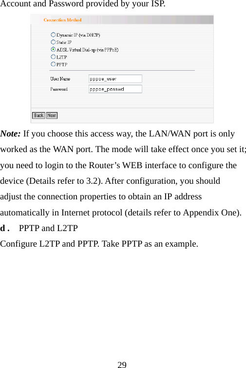
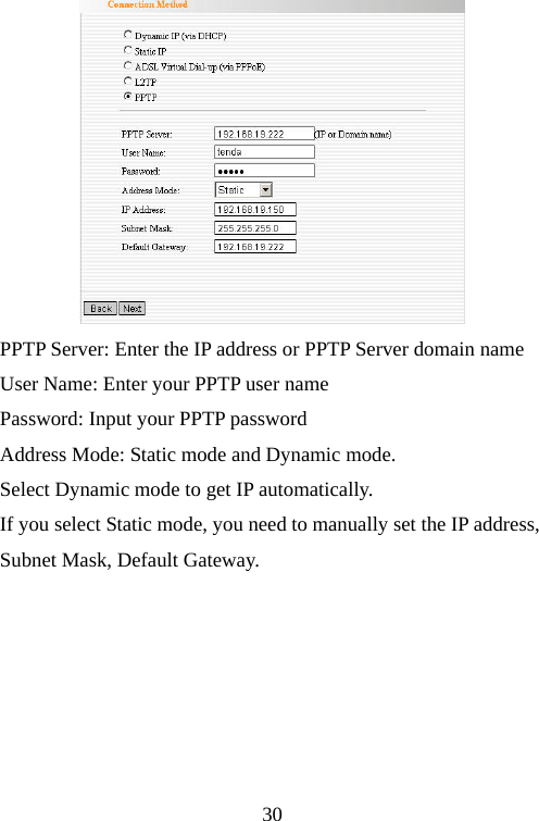
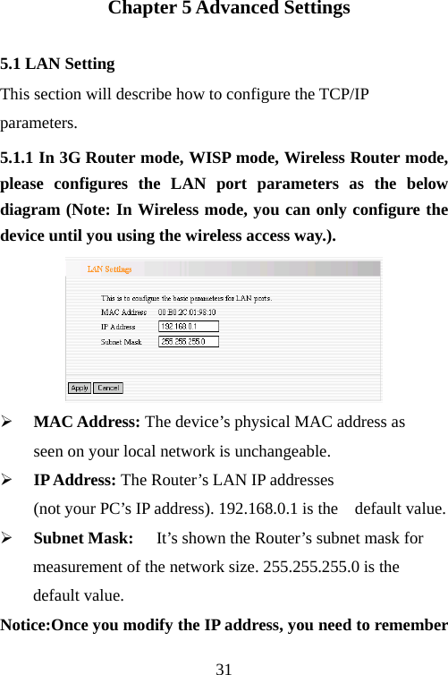
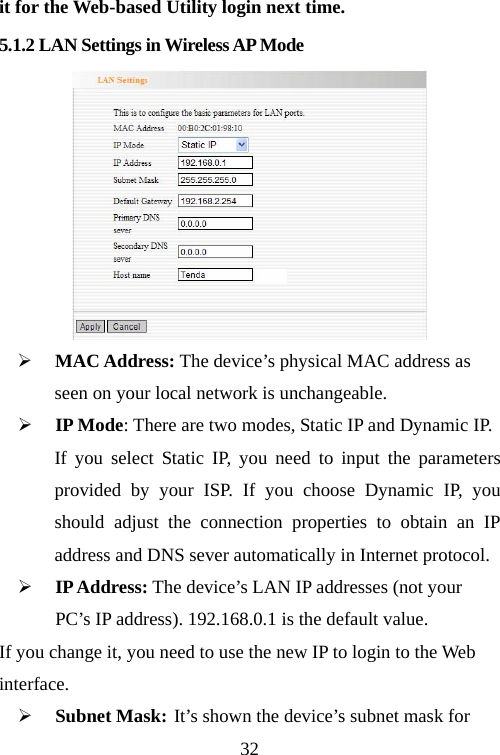
SHENZHEN TENDA TECHNOLOGY CO., LTD. 150Mbps Portable Wireless AP/Router 3G150M User Guide v1 0
UserManual.wiki
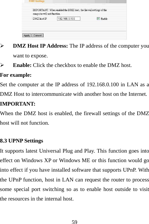
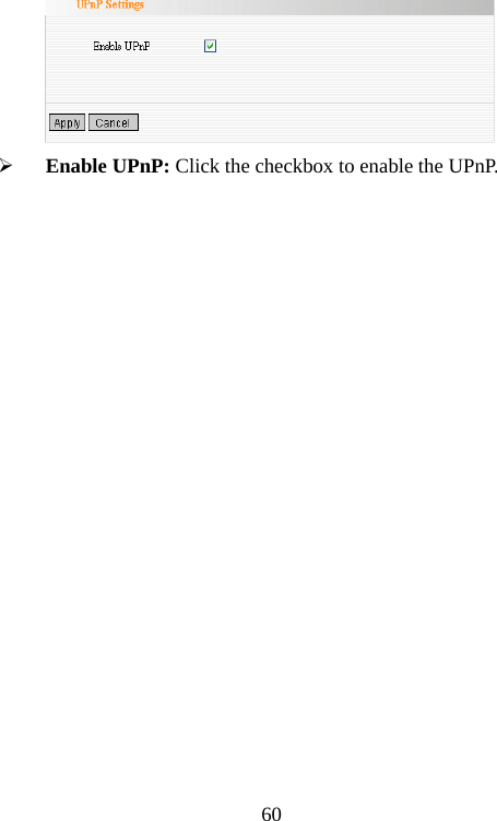
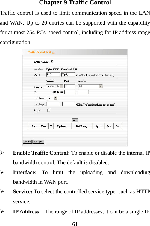
>
TENDA TECHNOLOGY
>
3G150M User Manual
manual
Navigation menu
Upload a User Manual
Namespaces
Wiki Guide
HTML
PDF
Info
Views
User Manual
Discussion / Help
Navigation
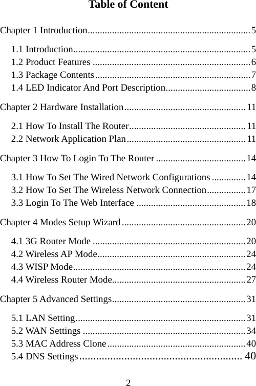
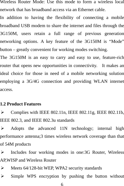
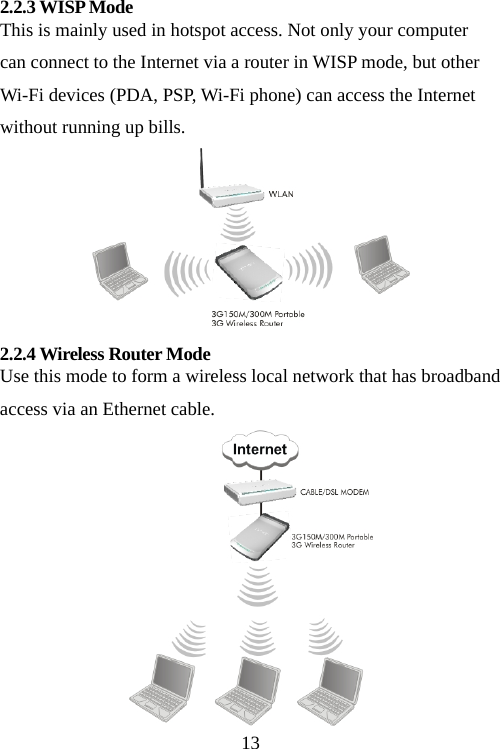
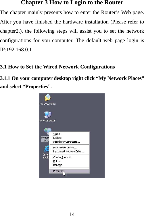
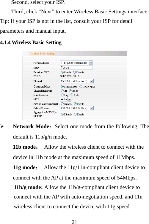
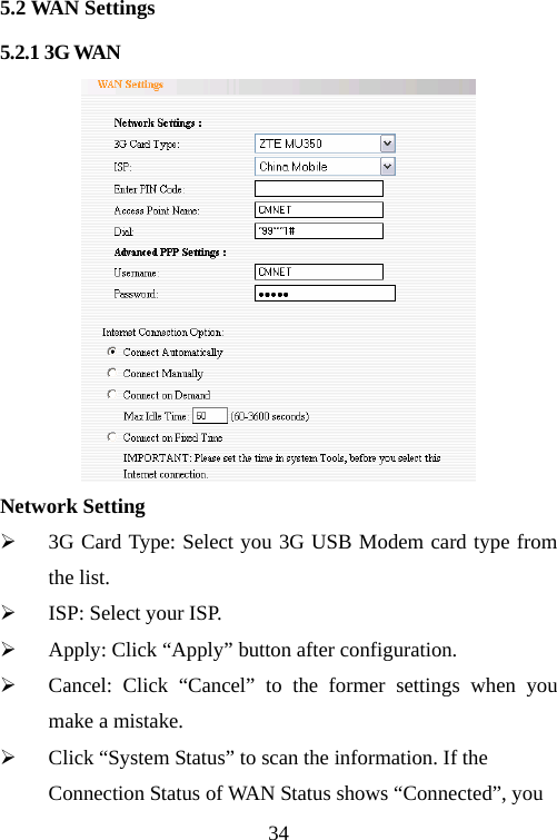
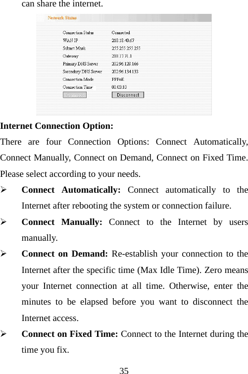

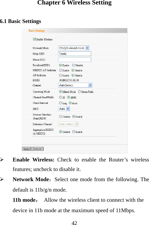
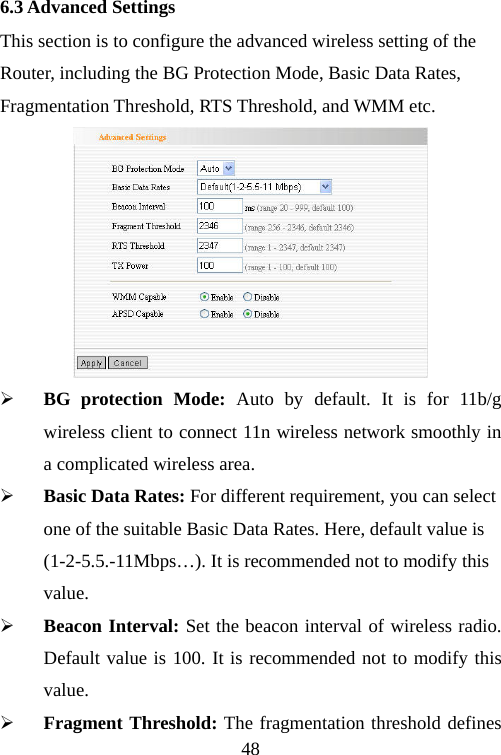
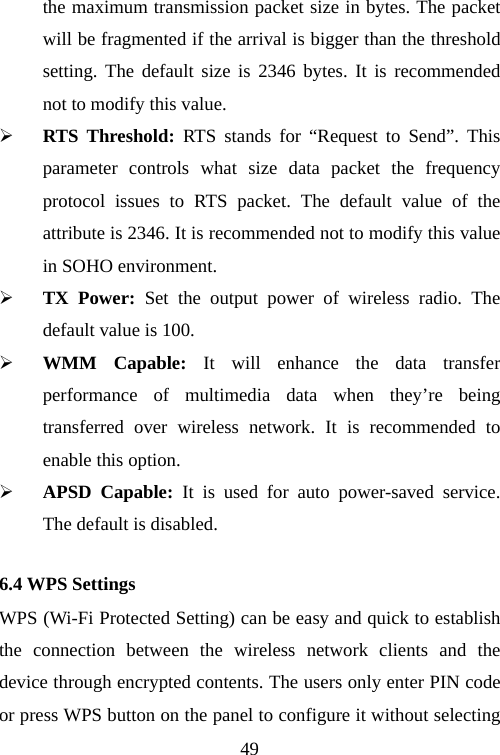
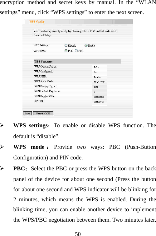
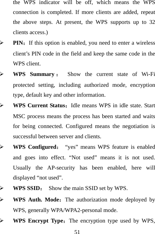
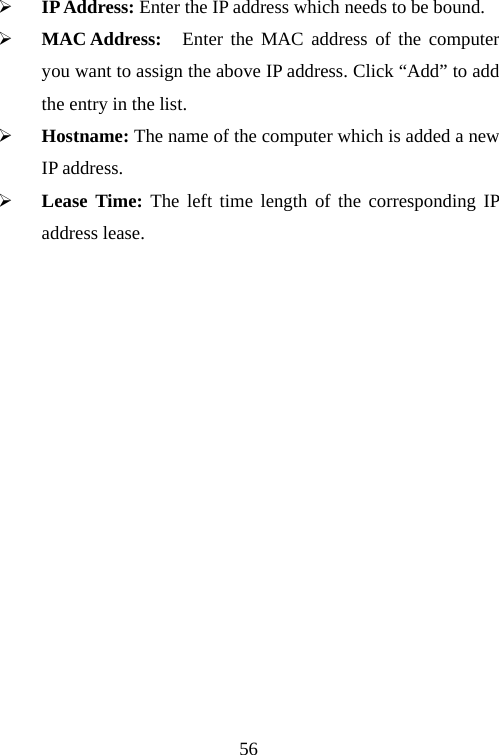
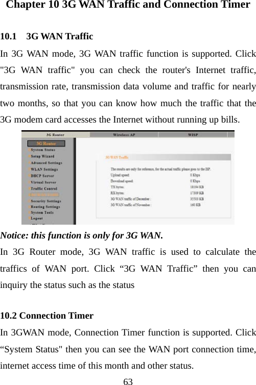
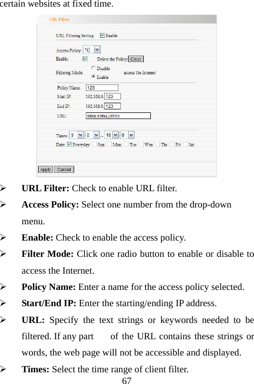
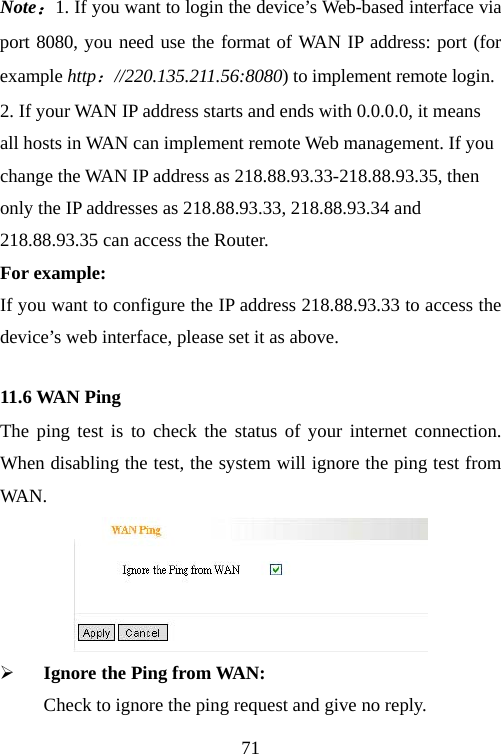
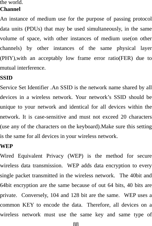
![44¾ Channel Bandwidth:Select the channel bandwidth to improve the wireless performance. When the network has 11b/g and 11n clients, you can select the 40M; when it is an 11n network, select 20/40M to improve its throughput. 6.2 Wireless Security Setting It is used to configure the AP network’s security setting. Here presents the common six (ten in all) encryption methods, including WPA-personal, WPA2-personal, Mixed WAP/WAP2-Personla, Mixed WEP, Open, Shared. It is suggested you choose WPA-personal for “Security Mode” and AES for “WPA Algorithms.” Please note that all connecting wireless devices will need to match these security settings in their connection settings. More details please refer to the Appendix Two. In this section, three common encryption methods are introduced. 6.2.1 WPA-Personal WPA (Wi-Fi Protected Access), a Wi-Fi standard, is a more recent wireless encryption scheme, designed to improve the security features of WEP. It applies more powerful encryption types (such as TKIP [Temporal Key Integrity Protocol] or AES [Advanced Encryption Standard]) and can change the keys dynamically on every authorized wireless device.](https://usermanual.wiki/TENDA-TECHNOLOGY/3G150M/User-Guide-1337241-Page-45.png)
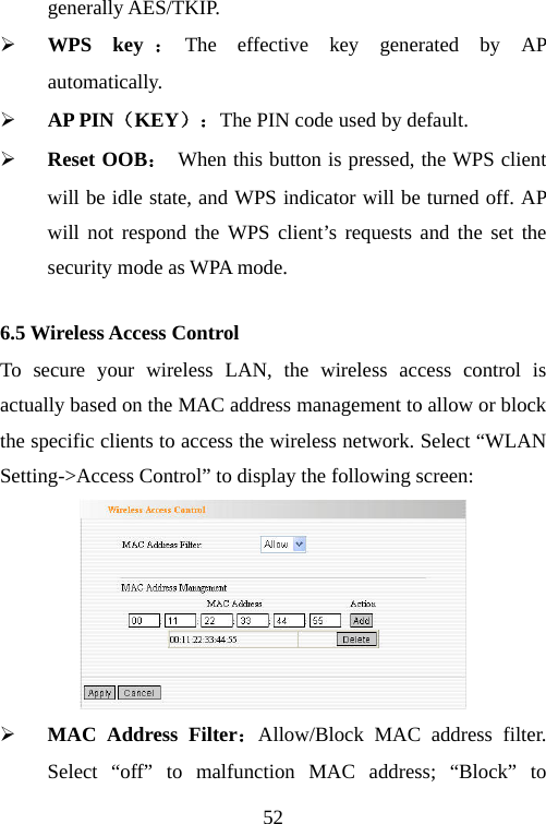
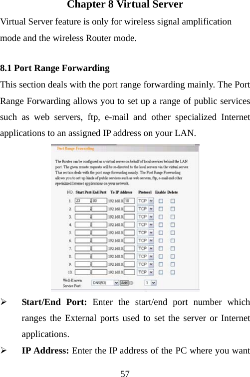
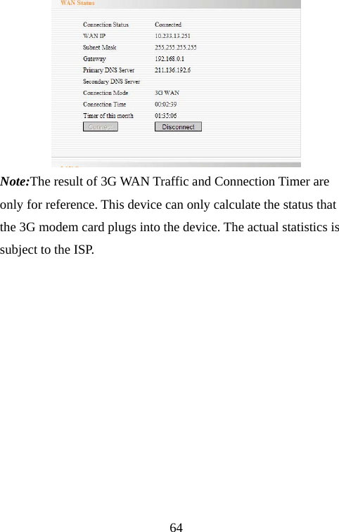
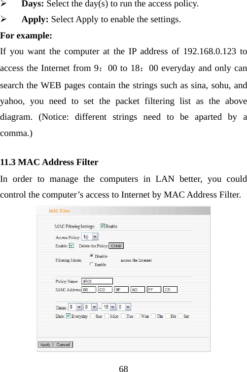
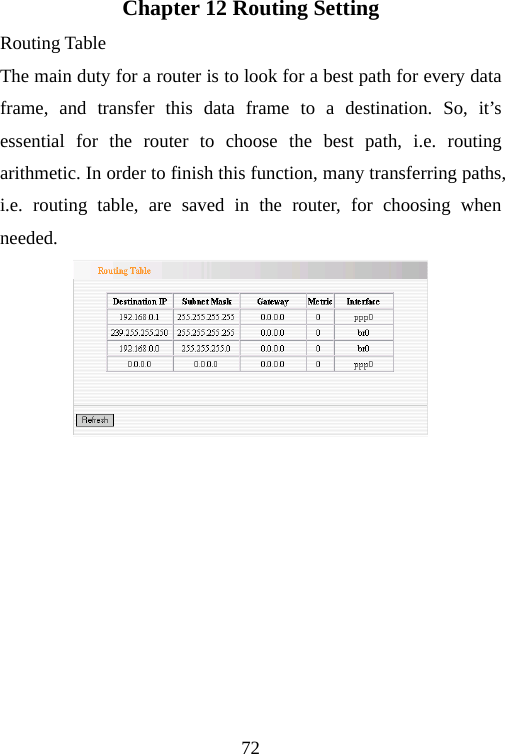
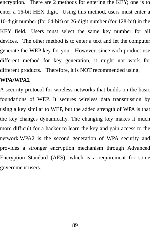
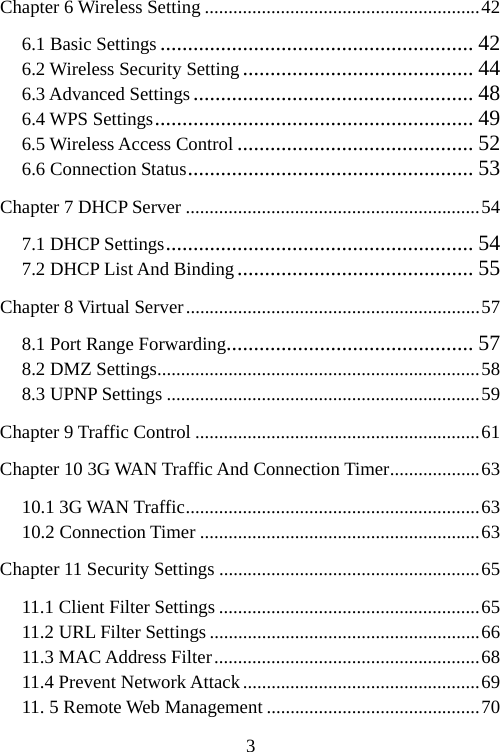
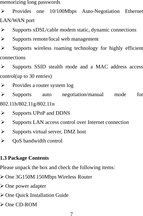
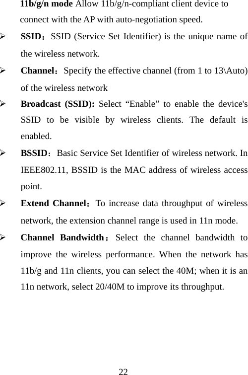
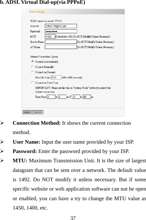
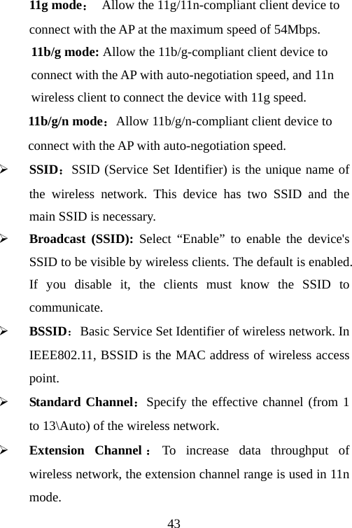
![45 ¾ WPA Algorithms:Provides TKIP [Temporal Key Integrity Protocol] or AES [Advanced Encryption Standard]. ¾ Pass Phrase: Enter the encrypted characters with 8-63 ASCII characters. ¾ Key Renewal Interval:Set the key’s renewal period. 6.2.2 WPA2- Personal WPA2 (Wi-Fi Protected Access version 2) provides higher security than WEP (Wireless Equivalent Privacy) or WPA (Wi-Fi Protected Access). Besides TKIP encryption, new AES encryption mode is provided.](https://usermanual.wiki/TENDA-TECHNOLOGY/3G150M/User-Guide-1337241-Page-46.png)
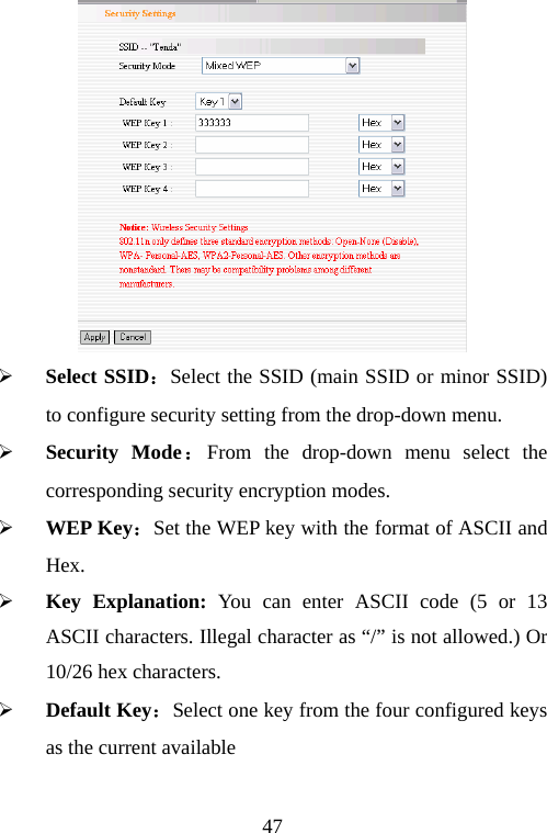
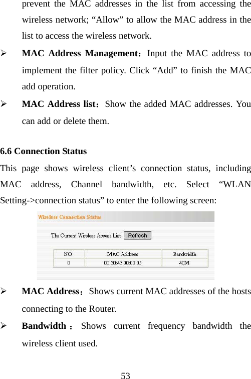
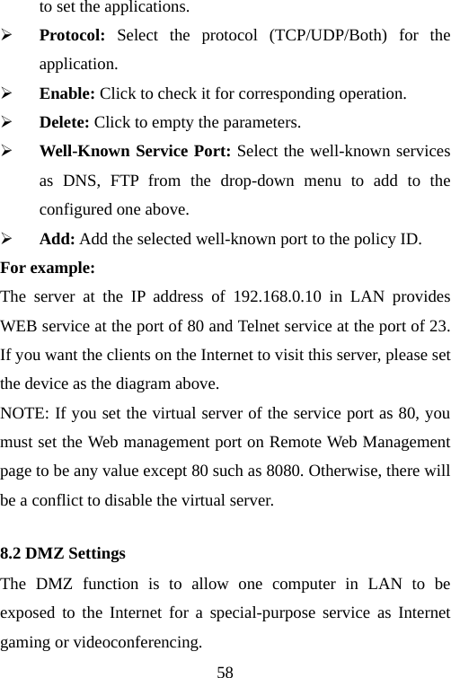
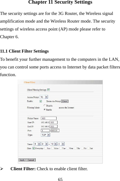
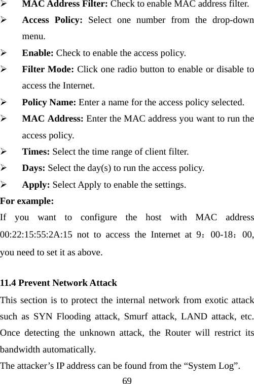
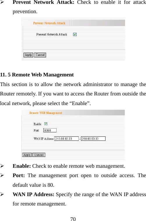
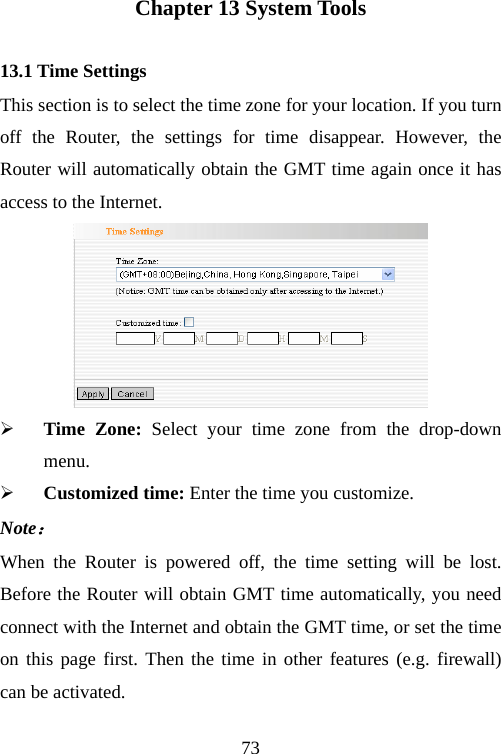
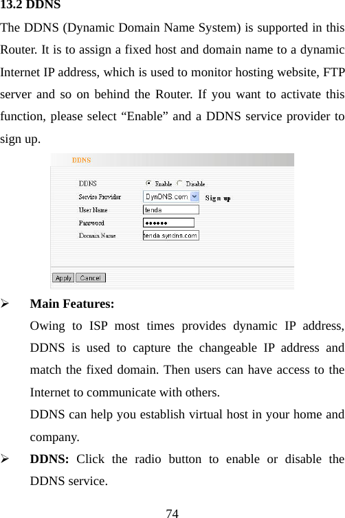
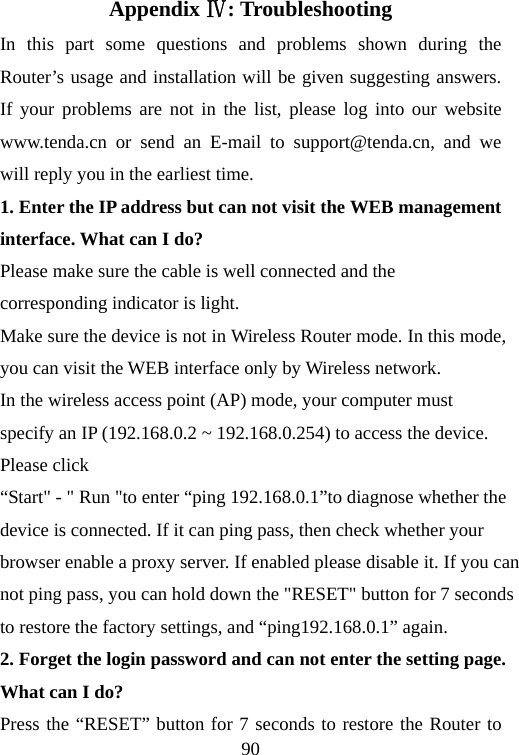
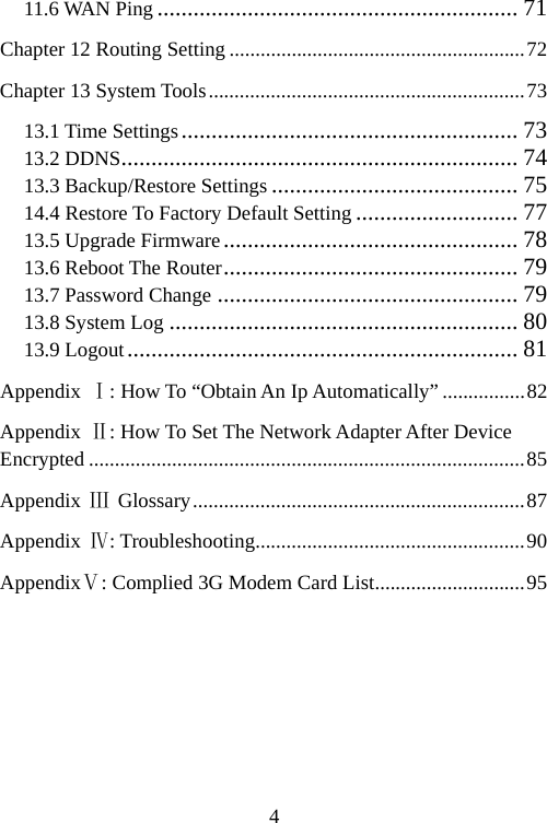
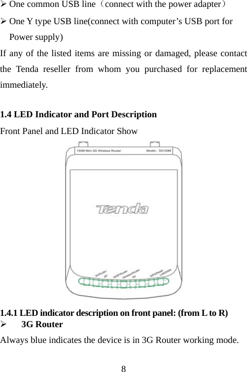
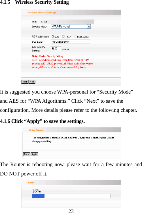
![46 ¾ WPA Algorithms:Provides TKIP [Temporal Key Integrity Protocol], AES [Advanced Encryption Standard] or TKIP&AES mixed mode. ¾ Pass Phrase:Enter the encrypted characters with 8-63 ASCII characters. ¾ Key Renewal Interval:Set the key’s renewal period. 6.2.3 Mixed WEP WEP (Wired Equivalent Privacy), a basic encryption method, usually encrypts wireless data using a series of digital keys (64 bits or 128 bits in length). By using the same keys on each of your wireless network devices, you can prevent unauthorized wireless devices from monitoring your transmissions or using your wireless resources. Select Mixed WEP to enter the following window:](https://usermanual.wiki/TENDA-TECHNOLOGY/3G150M/User-Guide-1337241-Page-47.png)