TENDA TECHNOLOGY A8 Wireless N150 Portable Router User Manual 2
SHENZHEN TENDA TECHNOLOGY CO., LTD. Wireless N150 Portable Router 2
UserManual.wiki
>
TENDA TECHNOLOGY
>
A8 User Manual
>
User manual_2
Contents
1.
User manual_1
2.
User manual_2
User manual_2
Navigation menu
Upload a User Manual
Namespaces
Wiki Guide
HTML
PDF
Info
Views
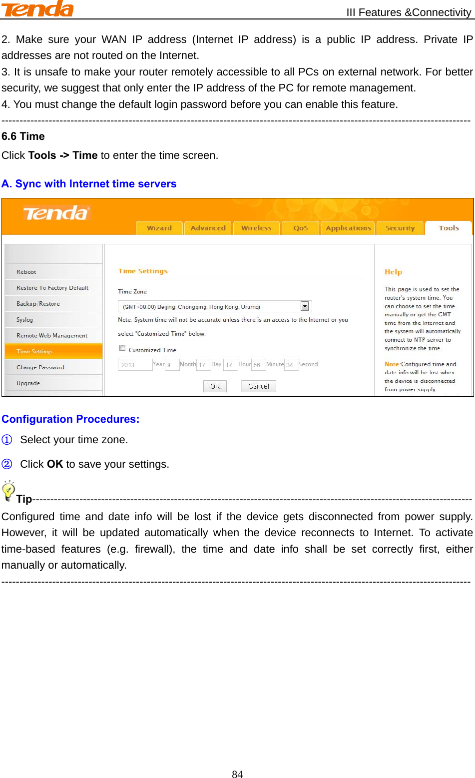
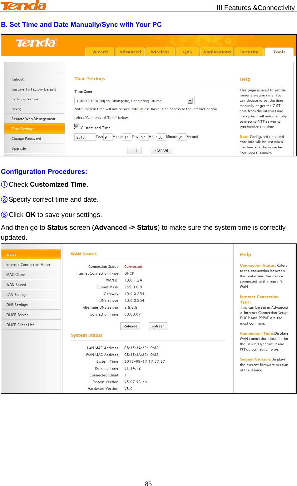
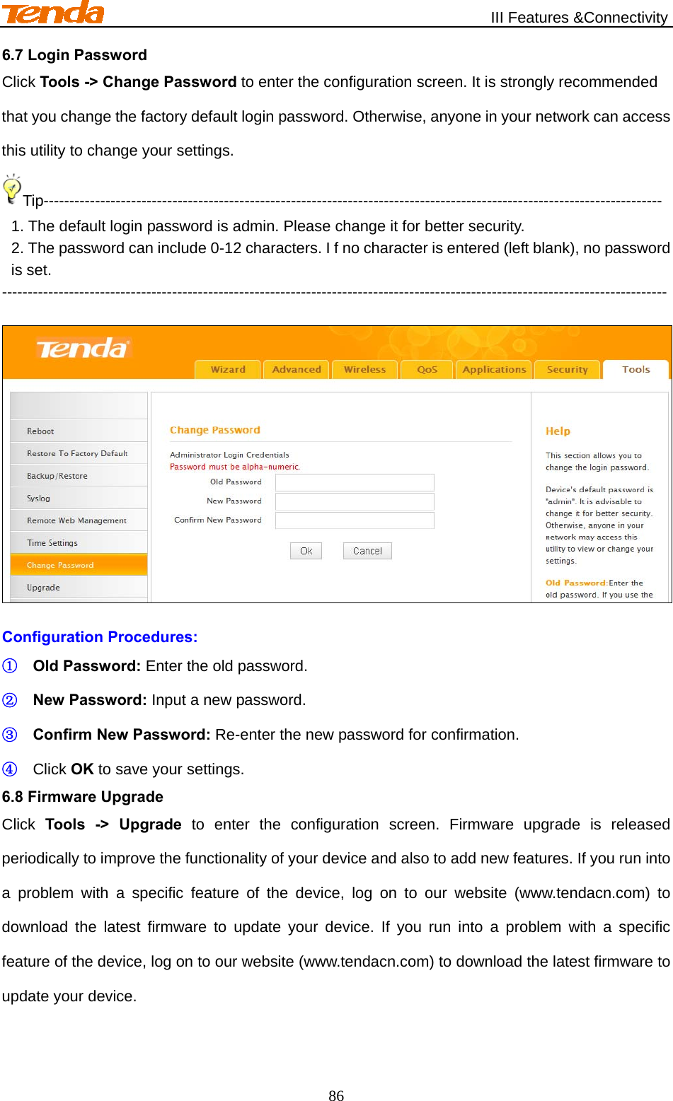
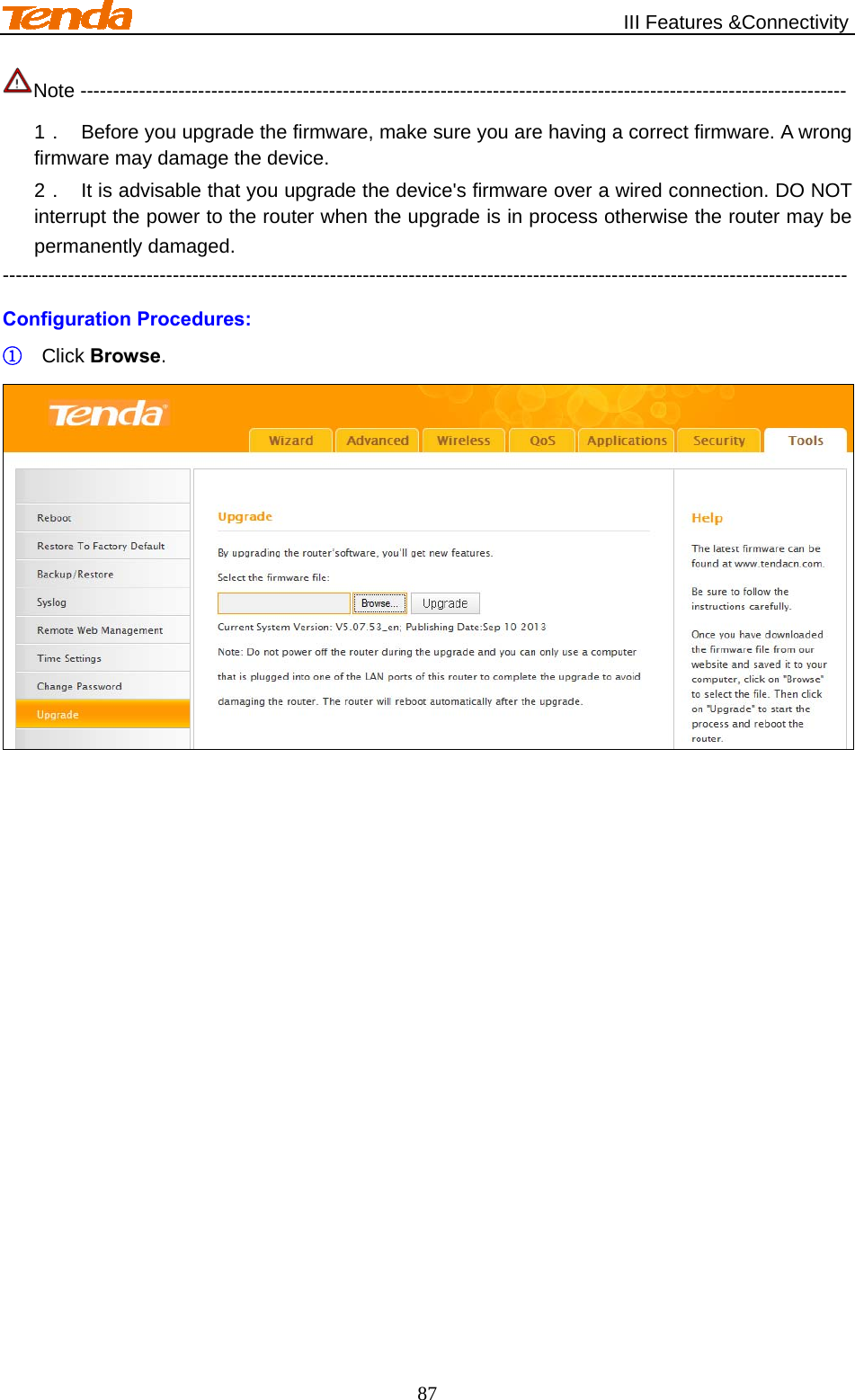
User Manual
Discussion / Help
Navigation