TENDA TECHNOLOGY AP4 300Mbps Wireless N Access Point User Manual
SHENZHEN TENDA TECHNOLOGY CO., LTD. 300Mbps Wireless N Access Point
User manual.pdf

i
Copyright Statement
© 2015 Shenzhen Tenda Technology Co., Ltd. All rights reserved.
Tenda is a registered trademark legally held by Shenzhen Tenda Technology Co., Ltd. Other brand and product
names mentioned herein are trademarks or registered trademarks of their respective holders. Copyright of the
whole product as integration, including its accessories and software, belongs to Shenzhen Tenda Technology Co.,
Ltd. No part of this publication can be reproduced, transmitted, transcribed, stored in a retrieval system, or
translated into any language in any form or by any means without the prior written permission of Shenzhen Tenda
Technology Co., Ltd.
Disclaimer
Pictures, images and product specifications herein are for references only. To improve internal design, operational
function, and/or reliability, Tenda reserves the right to make changes to the products without obligation to notify
any person or organization of such revisions or changes. Tenda does not assume any liability that may occur due
to the use or application of the product described herein. Every effort has been made in the preparation of this
document to ensure accuracy of the contents, but all statements, information and recommendations in this
document do not constitute the warranty of any kind, express or implied.
Technical Support
Phone:
(86 755)2765 7180
Fax:
(86 755)2765 7178
Email:
sales@tenda.com.cn
support@tenda.com.cn
Website:
http://www.tendacn.com

ii
Conventions
Thank you for choosing Tenda! Please read this user guide before you start. This user guide instructs you to install
and configure the router.
Typographical conventions in this User Guide:
Item
Presentation
Example
Button
Bold
“Click the Save button” can be simplified as
“Click Save”.
Menu
Bold
“The menu Basic” can be simplified as Basic.
Continuous Menus
>
Click Wireless > Basic
Symbols in this User Guide:
Item
Meaning
Note
This format is used to highlight information of importance or special
interest. Ignoring this type of note may result in ineffective
configurations, loss of data or damage to device.
Tip
This format is used to highlight a procedure that will save time or
resources.

iii
Contents
1 Product Overview ................................................................................................................................................... 1
Package Contents .................................................................................................................................................... 1
Hardware Description.............................................................................................................................................. 1
Front Panel.......................................................................................................................................................... 1
Back Panel .......................................................................................................................................................... 2
Label .................................................................................................................................................................. 3
2 Quick Internet Setup .............................................................................................................................................. 4
Step 1: Connect the AP for Configuration ................................................................................................................ 4
Step 2: Configure IP on Your PC ............................................................................................................................. 4
Windows 8 .......................................................................................................................................................... 4
Windows 7 .......................................................................................................................................................... 6
Windows XP ....................................................................................................................................................... 8
Step 3: Login to Its Web Manager .......................................................................................................................... 10
Step 4: Configure the Operation Mode ....................................................................................................................11
AP Mode ............................................................................................................................................................11
Station Mode ..................................................................................................................................................... 13
Universal Repeater Mode .................................................................................................................................. 15
WISP Mode ...................................................................................................................................................... 18
Client + AP Mode.............................................................................................................................................. 21
Step 5: Done! ........................................................................................................................................................ 24
3 Setup: Advanced ................................................................................................................................................... 25
How to Change the LAN IP Address ...................................................................................................................... 25
How to Configure DHCP Server Settings ............................................................................................................... 26
How to Configure Basic Wireless Settings ............................................................................................................. 27
How to Configure Advanced Wireless Settings ...................................................................................................... 30
How to Filter Access to Your Network ................................................................................................................... 31
How to Configure QVLAN Settings to Work with Switches ................................................................................... 32
How to Login to Web Manager in a More Secure Way ........................................................................................... 35
How to login to Web Manager via HTTP ........................................................................................................... 35
How to login to Web Manager via HTTPS ......................................................................................................... 35
How to Configure the Idle Timeout ....................................................................................................................... 36
How to Configure System Time for Your Device ................................................................................................... 36
How to Change the Login User Name and Password .............................................................................................. 37
4 Maintaining and Monitoring ................................................................................................................................ 39
How to Diagnose Your Network ............................................................................................................................ 39
Site Survey........................................................................................................................................................ 39
Ping .................................................................................................................................................................. 40
Traceroute ......................................................................................................................................................... 41
How to Reboot Your AP ........................................................................................................................................ 42
Reboot Regularly .............................................................................................................................................. 42

iv
Reboot Manually ............................................................................................................................................... 43
How to Reset Your AP ........................................................................................................................................... 43
How to Upgrade Your AP ...................................................................................................................................... 43
How to Backup and Restore Your AP’s Configurations .......................................................................................... 44
How to View System Info and Wireless Info of Your AP ........................................................................................ 45
How to View DHCP Client Information ................................................................................................................. 46
How to View Wireless Clients Information ............................................................................................................ 46
How to View the History of Your AP’s Actions ...................................................................................................... 46
Appendix ................................................................................................................................................................. 48
A With PoE Setup ................................................................................................................................................. 48
B Connect to Your WiFi ........................................................................................................................................ 48
Windows 8 ........................................................................................................................................................ 49
Windows 7 ........................................................................................................................................................ 50
Windows XP ..................................................................................................................................................... 51
C FAQs ................................................................................................................................................................. 52
D Safety & Emission Statement ............................................................................................................................. 53
1
1 Product Overview
Package Contents
Open the package and verify that the following items are included:
Wireless AP
Power Adapter
PoE Injector
Ethernet Cable
Install Guide
GNU
If any item is incorrect, missing, or damaged, please contact your dealer for immediate replacement.
Hardware Description
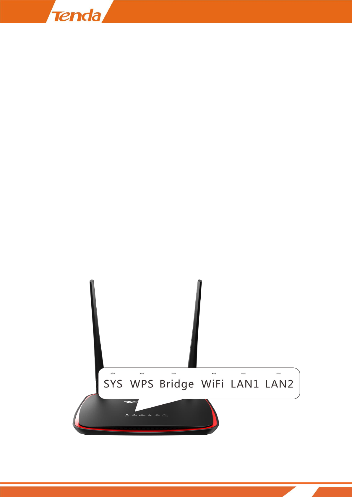
Front Panel
2
LED
Status
Description
SYS
Off
Malfunction occurs or the device is not powered on.
Blinking
The device is working properly.
WPS
Off
WPS is disabled or WPS authentication negotiation is completed.
Blinking
The device is negotiating with the uplink ADSL Modem or Wi-Fi Router.
Bridge
(Not apply to AP mode)
Off
Not bridged
Solid
Bridged successfully
WiFi
Off
WiFi is disabled.
Solid
WiFi is enabled.
Blinking
Data is being transmitted wirelessly.
LAN1/LAN2
Off
There is no device linked to the corresponding port.
Solid
There is a device linked to the corresponding port but no activity.
Blinking
Data transmission is occurring on the corresponding port.
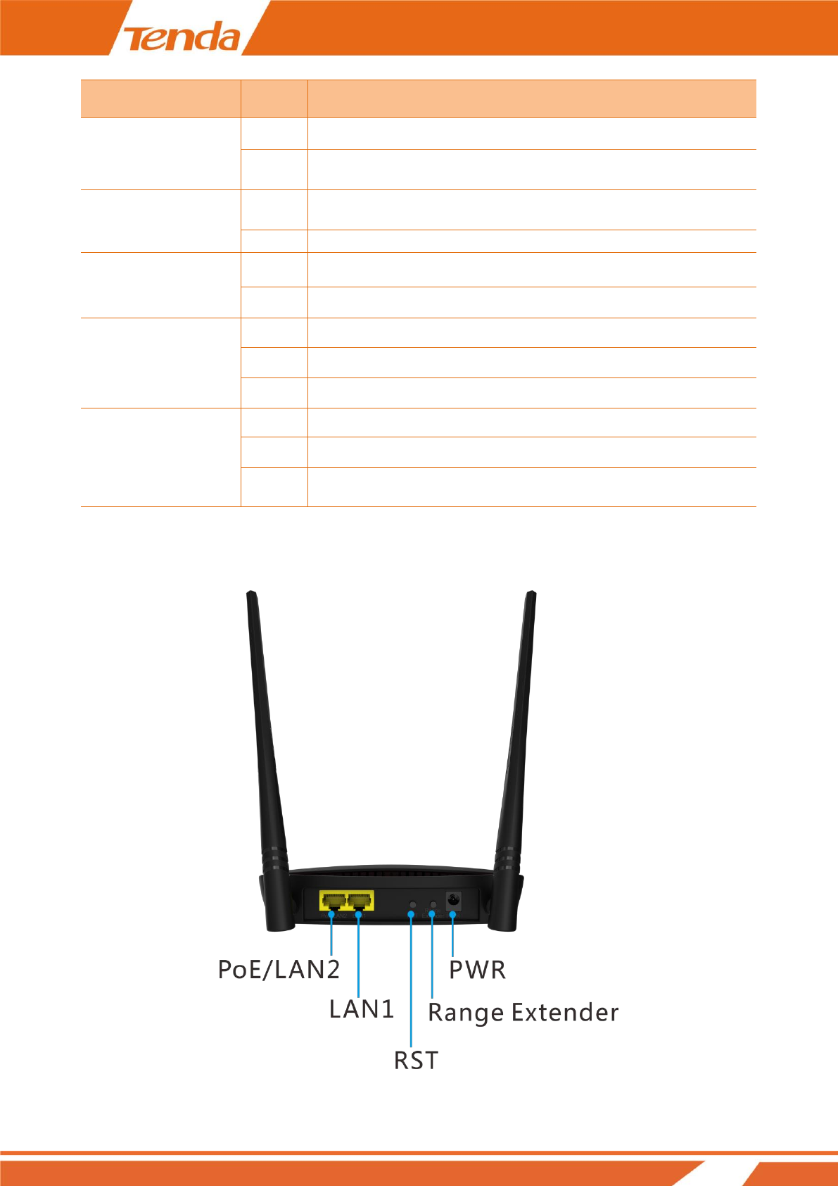
Back Panel
3
Port/Button
Description
PoE/LAN2
1) PoE port for connecting to the included PoE injector for power supply.
2) 100Mbps Ethernet LAN port for connecting to the local device, like a
computer, a switch, etc.
LAN1
100Mbps Ethernet LAN port for connecting to the local device, like a computer, a
switch, etc.
RST
Pressing it for over 7 seconds restores this device to its factory defaults.
Range
Extender
Used for boosting Wi-Fi range.
Press and hold it (for 3 seconds) until the WPS LED blinks and the device starts to
bridge the uplink ADSL modem or Router. The Bridge LED turns on when
bridged successfully, and the WPS LED will be off.
PWR
Used for connecting to the included power adapter for power supply.
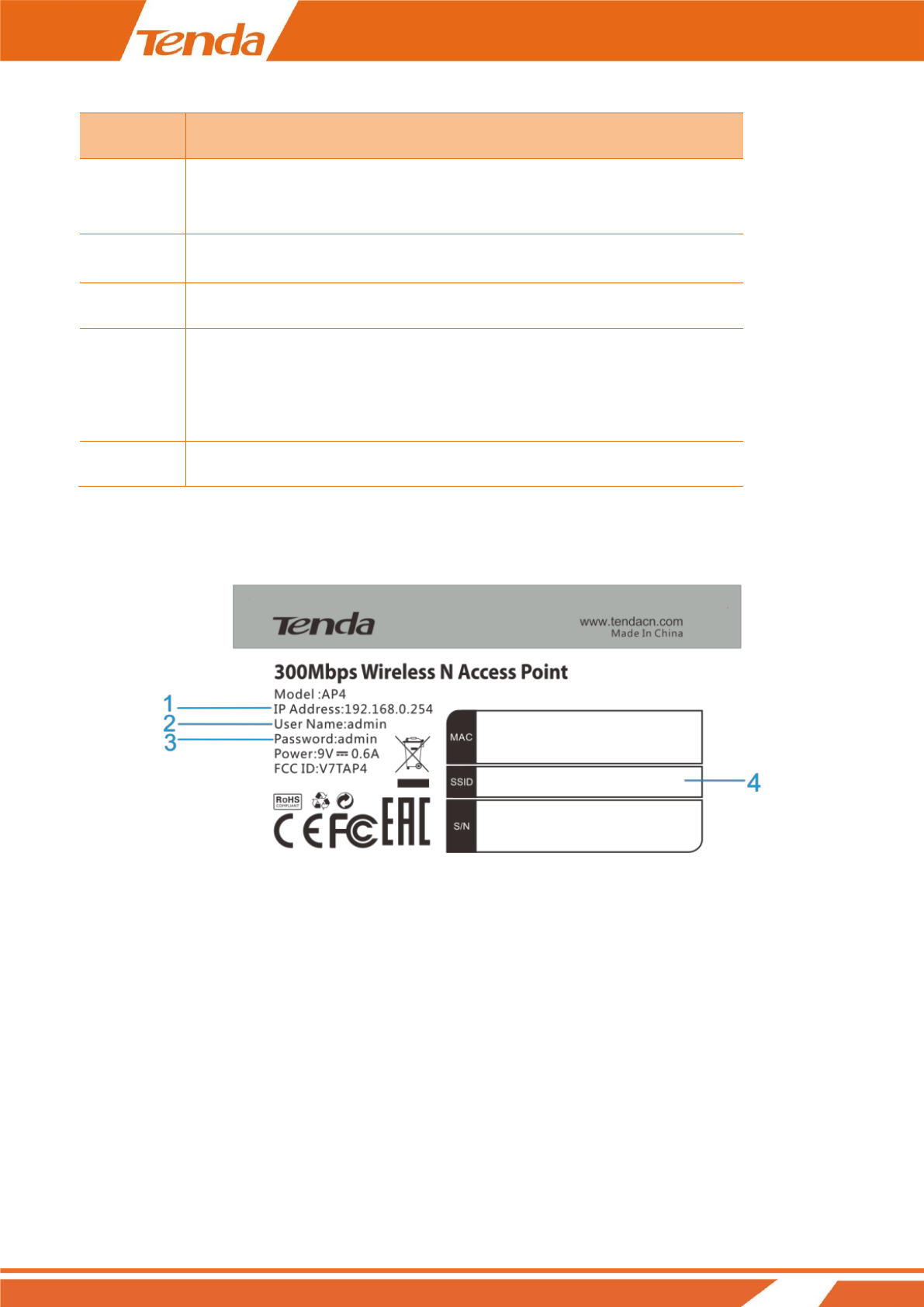
Label
1. Default login IP address for web login of this device.
2. Default login user name.
3. Default login password.
4. SSID: Default WiFi name of this device which you will need when connecting to your WiFi.
4
2 Quick Internet Setup
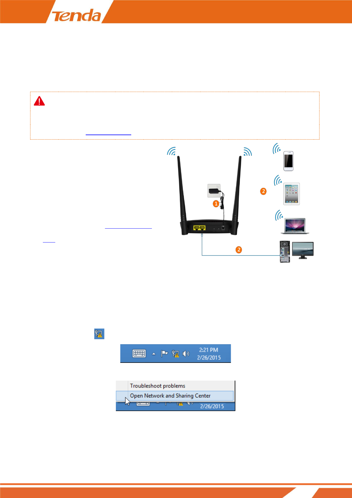
Step 1: Connect the AP for Configuration
Note:
If the AP deployment location is far away from the power outlet, you can refer to the Power over Ethernet (PoE)
solution in appendix A With PoE Setup.
Step 2: Configure IP on Your PC
Windows 8
❶ Right click the icon on the bottom right corner of your desktop.
❷ Click Open Network and Sharing Center.
❶ Connect the AP to power supply.
❷ Connect to the AP with the Ethernet cable
or via wireless. For connecting to it
wirelessly, see appendix B Connect to Your
WiFi.
5
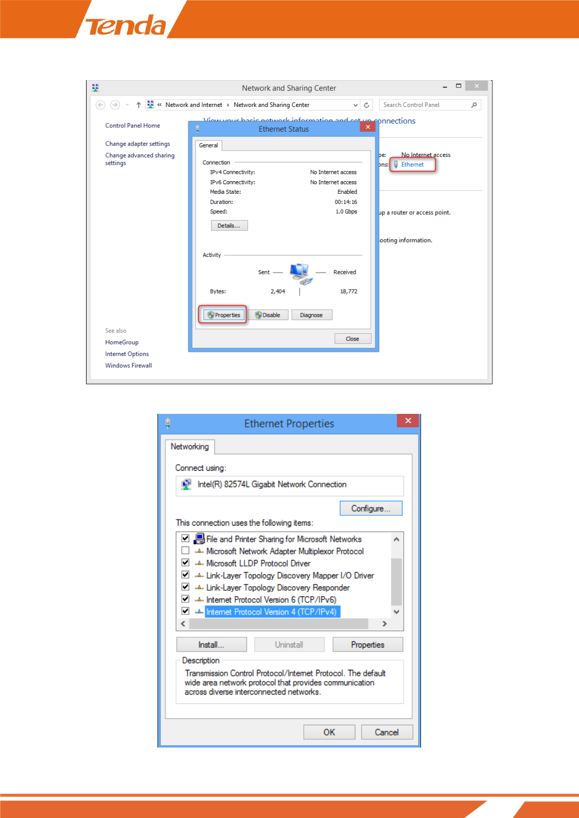
❸ Click Ethernet > Properties.
❹ Find and double click Internet Protocol Version 4(TCP/IPv4).
6
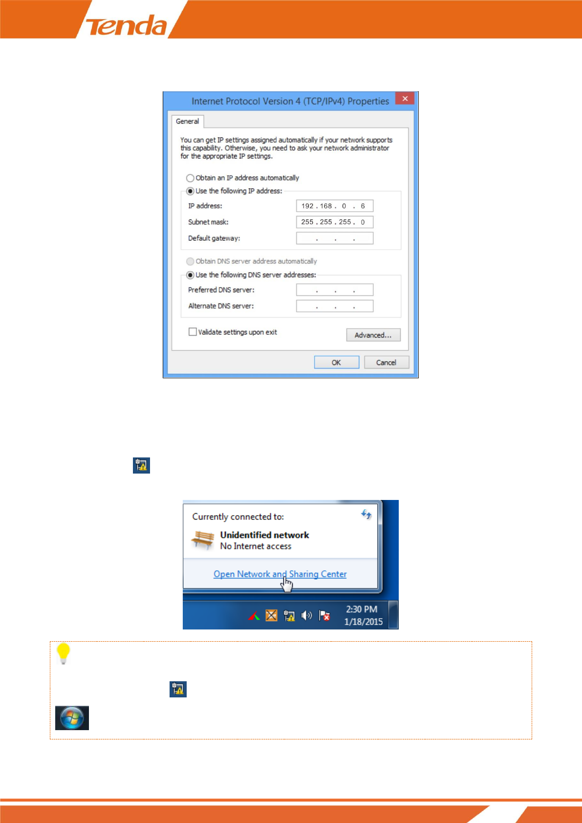
❺ Select Use the following IP address, type in the IP address: 192.168.0.x (2~253), Subnet mask:
255.255.255.0 and click OK.
❻ Click OK on the Ethernet Properties window.
Windows 7
❶ Click the icon on the bottom right corner of your desktop.
❷ Click Open Network and Sharing Center.
Tip
If you cannot find the icon on the bottom right corner of your desktop, follow steps below: Click Start
> Control Panel > Network and Internet > Network and Sharing Center.
7
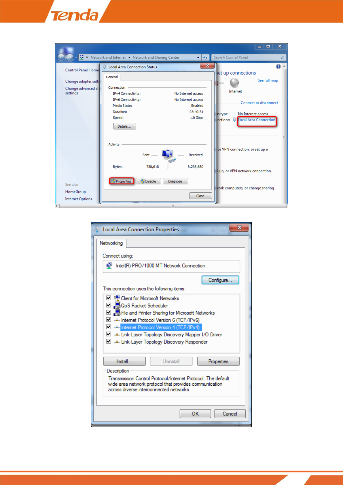
❸ Click Local Area Connection > Properties.
❹ Find and double click Internet Protocol Version 4(TCP/IPv4).
8
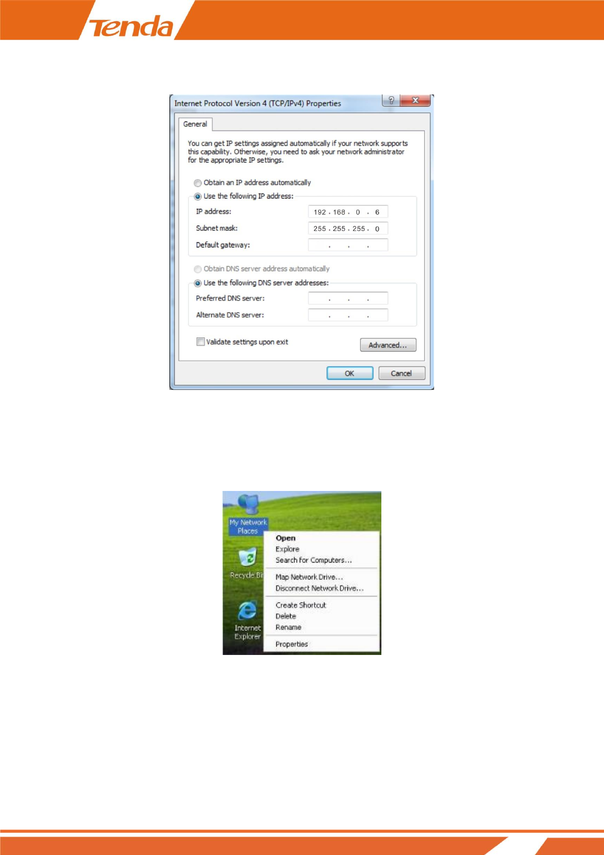
❺ Select Use the following IP address, type in the IP address: 192.168.0.x (2~253), Subnet mask:
255.255.255.0 and click OK.
❻ Click OK on the Local Area Connection Properties window.
Windows XP
❶ Right click My Network Places on your desktop and select Properties.
9
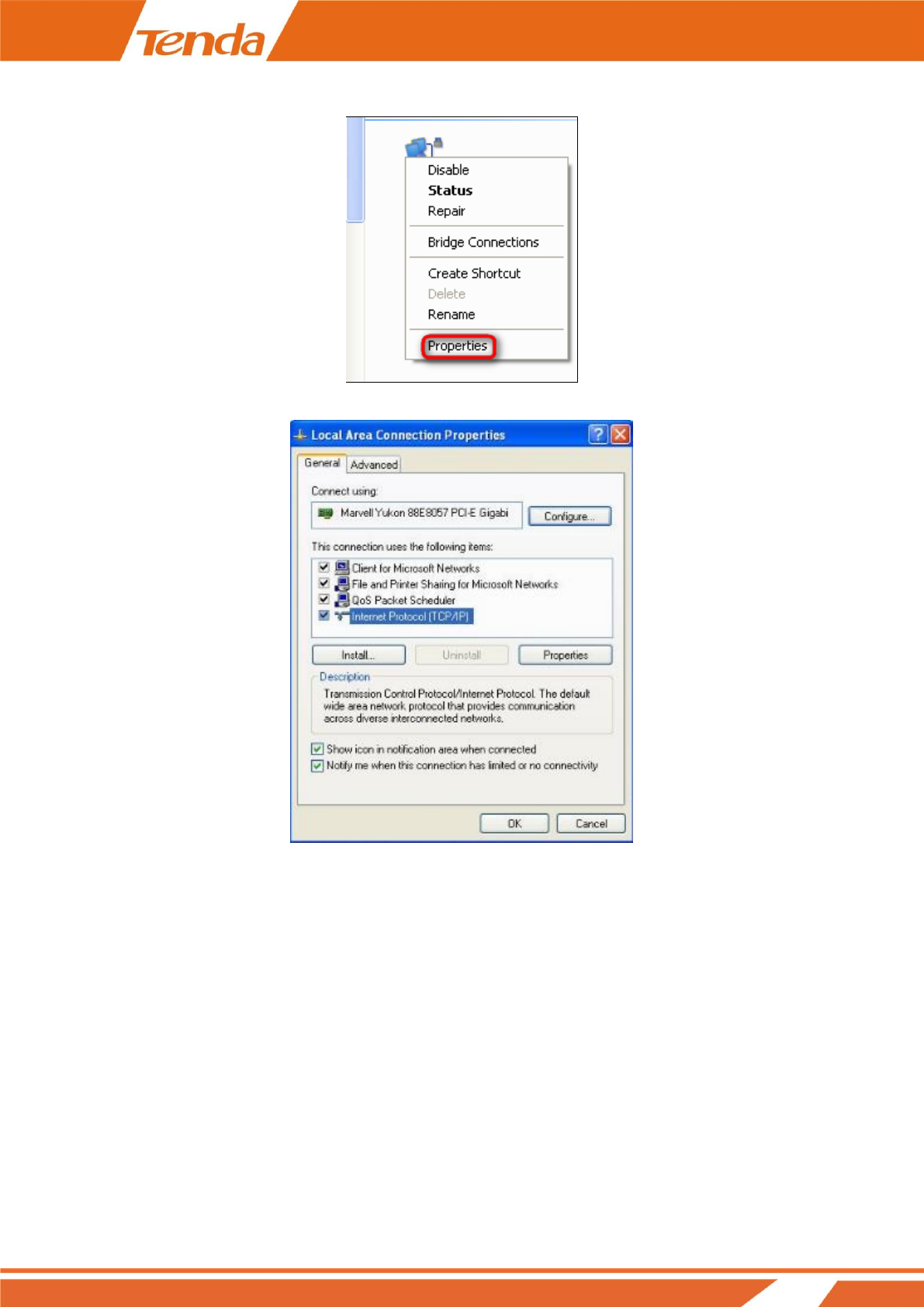
❷ Right click Local Area Connection and select Properties.
❸ Scroll down to find and double click Internet Protocol (TCP/IP).
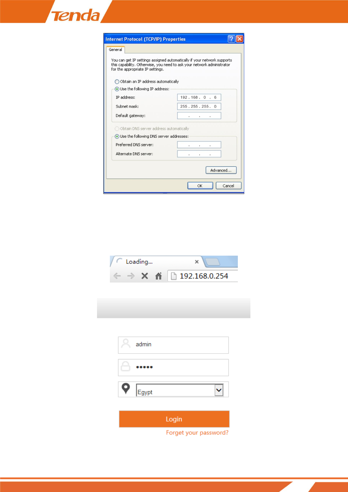
❹ Select Use the following IP address, type in the IP address: 192.168.0.x (2~253), Subnet mask:
255.255.255.0 and click OK.
10
❺ Click OK on the Local Area Connection Properties window.
Step 3: Login to Its Web Manager
1. Input 192.168.0.254 in a web browser’s address bar, and then press Enter or Return on your keyboard.
2. Enter the default user name and password (admin for both) and click Login.
11
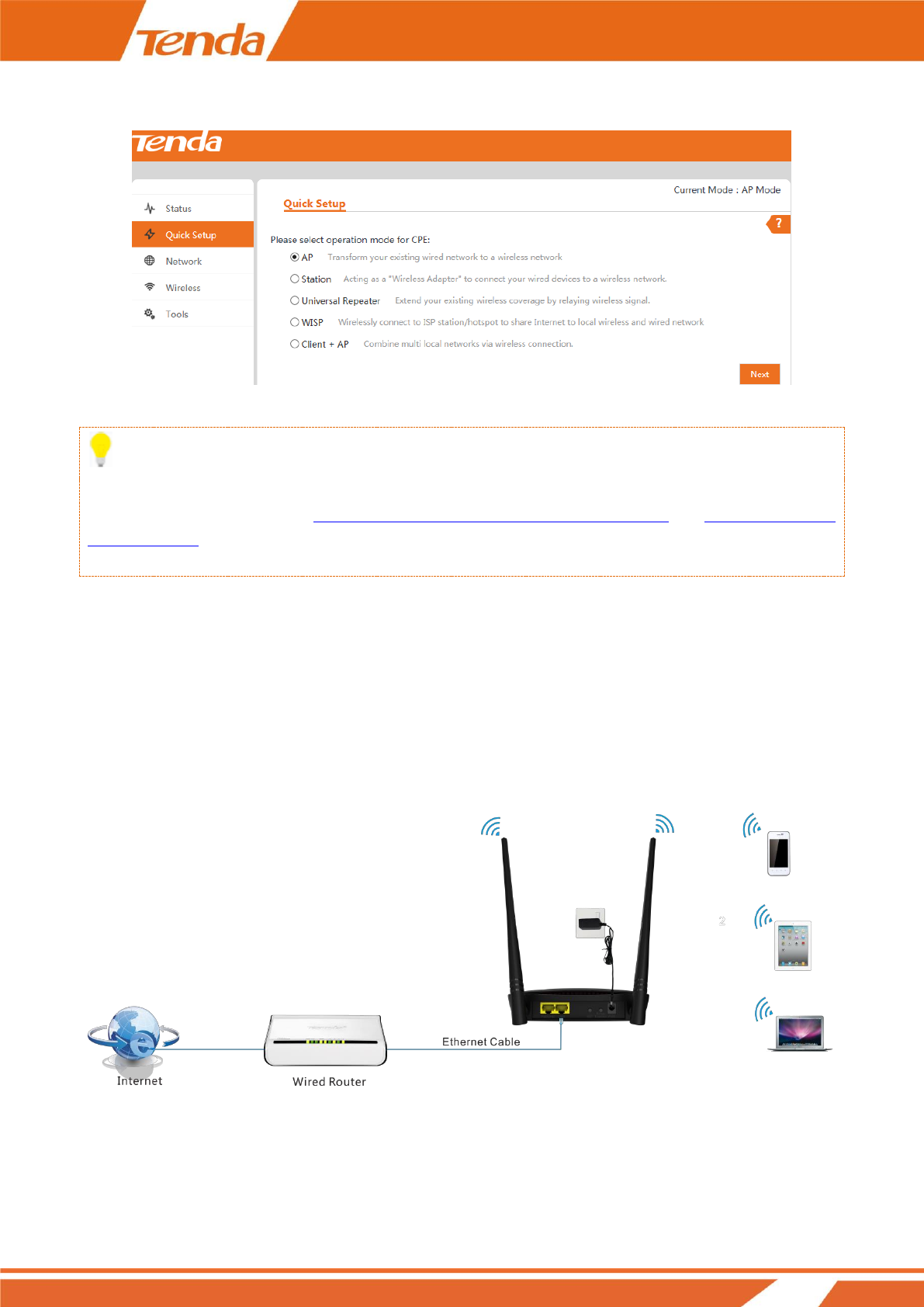
3. Please select the proper operating mode according to your needs and click Next to finish mode settings.
5 modes are available here. Next we will introduce them one by one.
Tip:
After successful login, for your network security, it is advisable to modify your login user name, password and
LAN IP address. For details, see How to Change the Login User Name and Password and How to Change the
LAN IP Address. Once you’ve changed the login user name, password and LAN IP address, do remember to use
the new ones to login to its web manager.
Step 4: Configure the Operation Mode
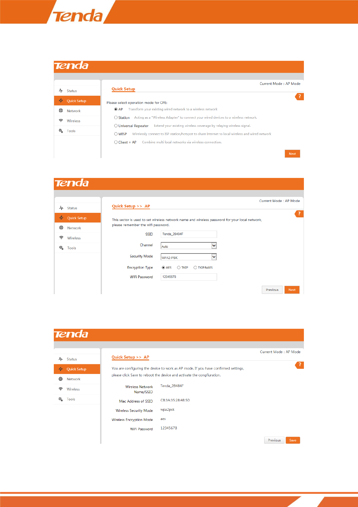
AP Mode
In this mode, this device works as an access point to transform your existing wired network into a wireless
network.
12
Settings:
❶ Select AP mode on Quick Setup page and click Next.
❷ Set a WiFi name and WiFi password for your local network and click Next.
❸ Note down your WiFi name and password on this page and click Save to apply your settings. Wait until the
device restarts successfully.
13
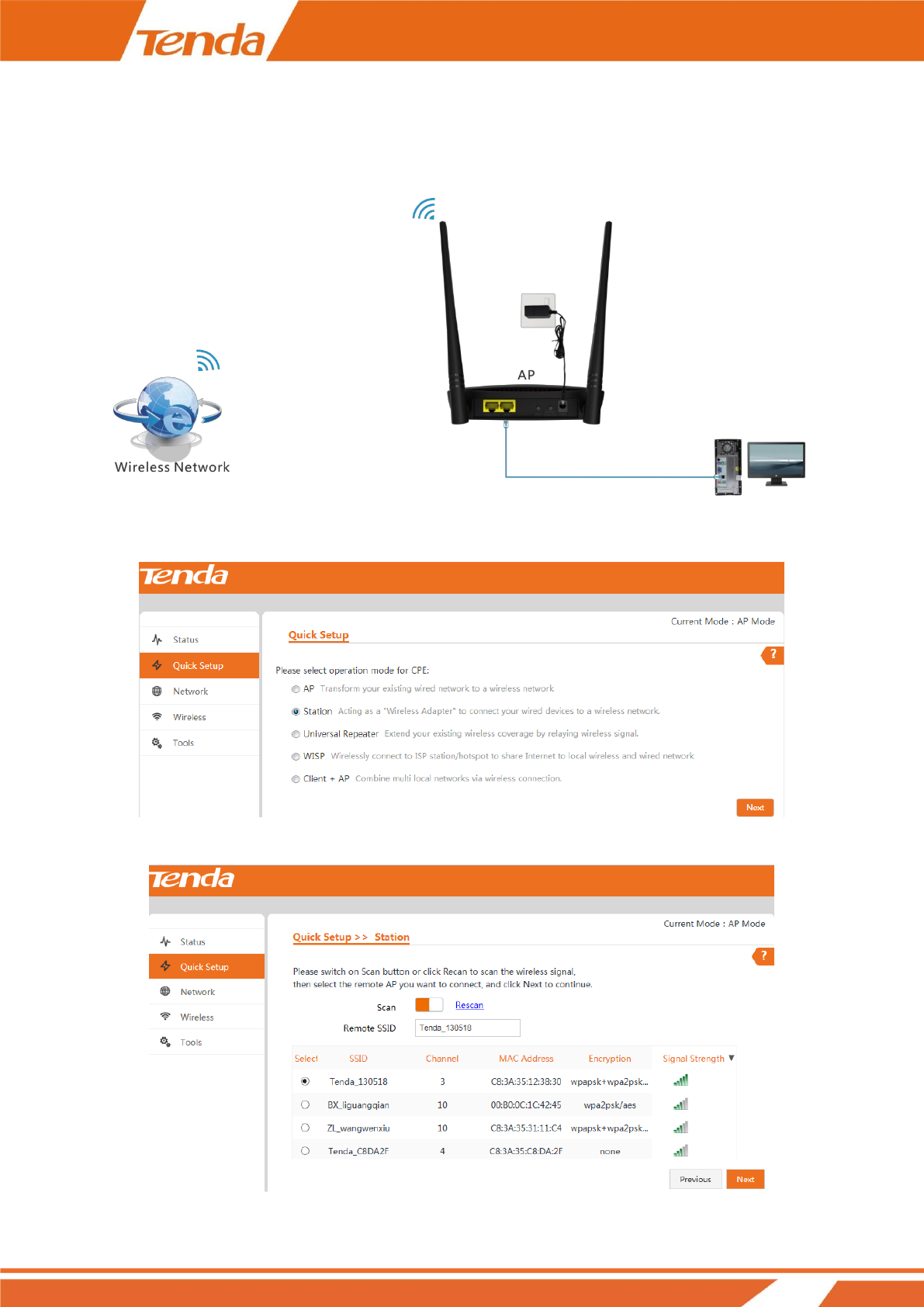
Station Mode
In this mode, the AP will work as an adapter to connect your wired devices to a wireless network.
Settings
❶ Select Station mode on Quick Setup page and click Next.
❷ Click the Scan button, select the remote SSID (WiFi name) and click Next.
14
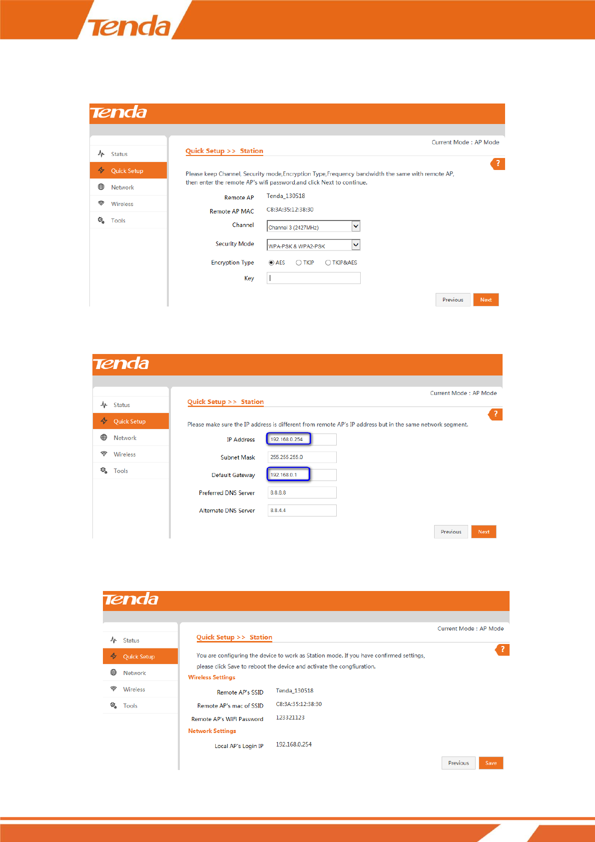
❸ The security mode will be selected automatically, please confirm it and enter the WiFi password of the uplink
ADSL modem or router in the Key field and click Next.
❹ Make sure that the IP address is a different one but on the same network segment as that of the uplink ADSL
modem or router and then click Next.
❺ Note down your SSID (WiFi name) and WiFi password on this page and click Save to apply your settings.
Wait until the device restarts successfully.
15
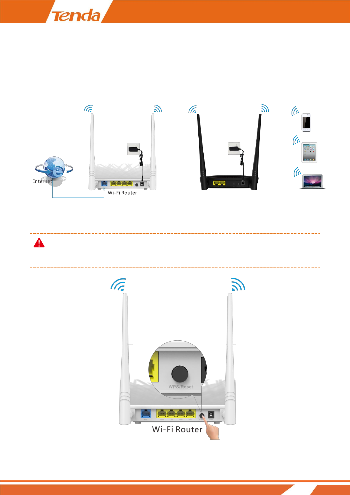
Universal Repeater Mode
In this mode, the AP can extend the WiFi range of the uplink ADSL modem or router. It’s an ideal solution for
large house, villa, eatery, store, etc. As compatibility problems may exist among routers of different manufacturers,
it is not advisable to bridge a device from other manufacturers.
Settings
Method 1: Boost WiFi Range via Button
Note:
1. As for this method, there should be a WPS button on the uplink ADSL modem or router.
❶ Press the WPS button on the uplink ADSL modem or router until the WPS LED blinks.
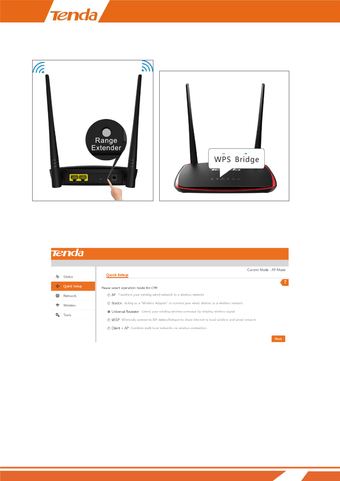
16
❷ Within 2 minutes, press the Range Extender button on the AP4 for 3 seconds until the WPS LED is blinking.
Then the AP will start to connect to the ADSL modem or Router.
❸ The AP connects to the ADSL modem or router successfully when the Bridge LED is on.
Method 2: Boost WiFi Range via Web UI
❶ Select Universal Repeater mode on Quick Setup page and click Next.
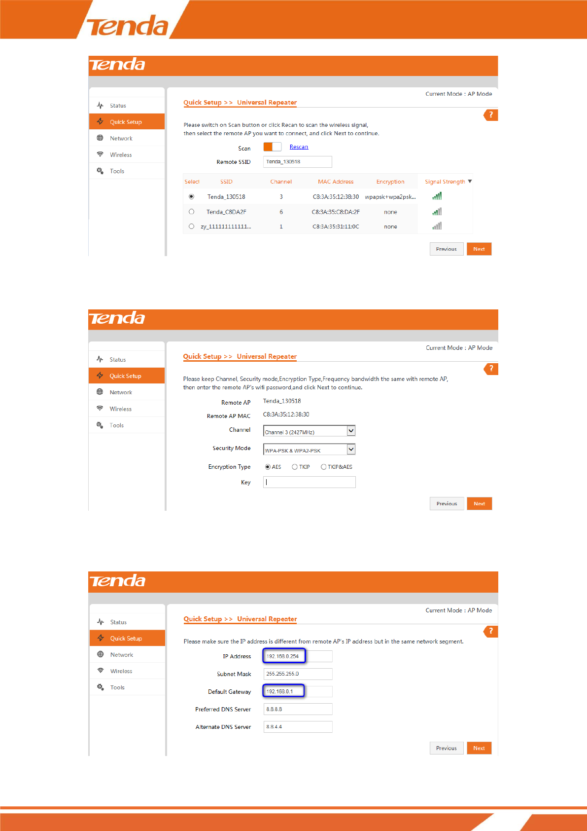
❷ Click the Scan button, select the remote SSID (WiFi name) from the list and click Next.
17
❸ The security mode will be selected automatically, please confirm it and enter the WiFi password of the uplink
ADSL modem or router in the Key field and click Next.
❹ Make sure the IP address is a different one but on the same network segment as that of the uplink ADSL
modem or router and click Next.
18
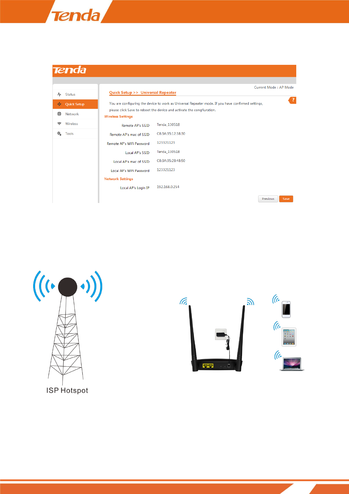
❺ Note down your SSID (WiFi name) and WiFi password on this page and click Save to apply your settings.
Wait until the device restarts successfully.
WISP Mode
In this mode, this device connects to ISP station or hotspot wirelessly to share network with local wireless and
wired devices. It is an ideal solution for residential districts.

19
Settings
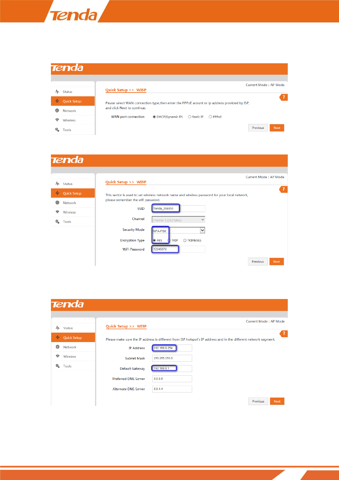
❶ Select WISP mode on Quick Setup page and click Next.
❷ Click the Scan button, select the remote SSID (WiFi name) you wish to and click Next.
❸ The security mode will be selected automatically, please confirm it and enter the WiFi password of the uplink
ADSL modem or router in the Key field and click Next.
20
❹ Select the WAN connection type according to your needs, finish corresponding Internet setups, and then click
Next.
❺ Customize your SSID (WiFi name), configure security settings for your SSID and click Next.
❻ Make sure that the IP address is on a different network segment from that of the ISP hotspot and then click
Next.
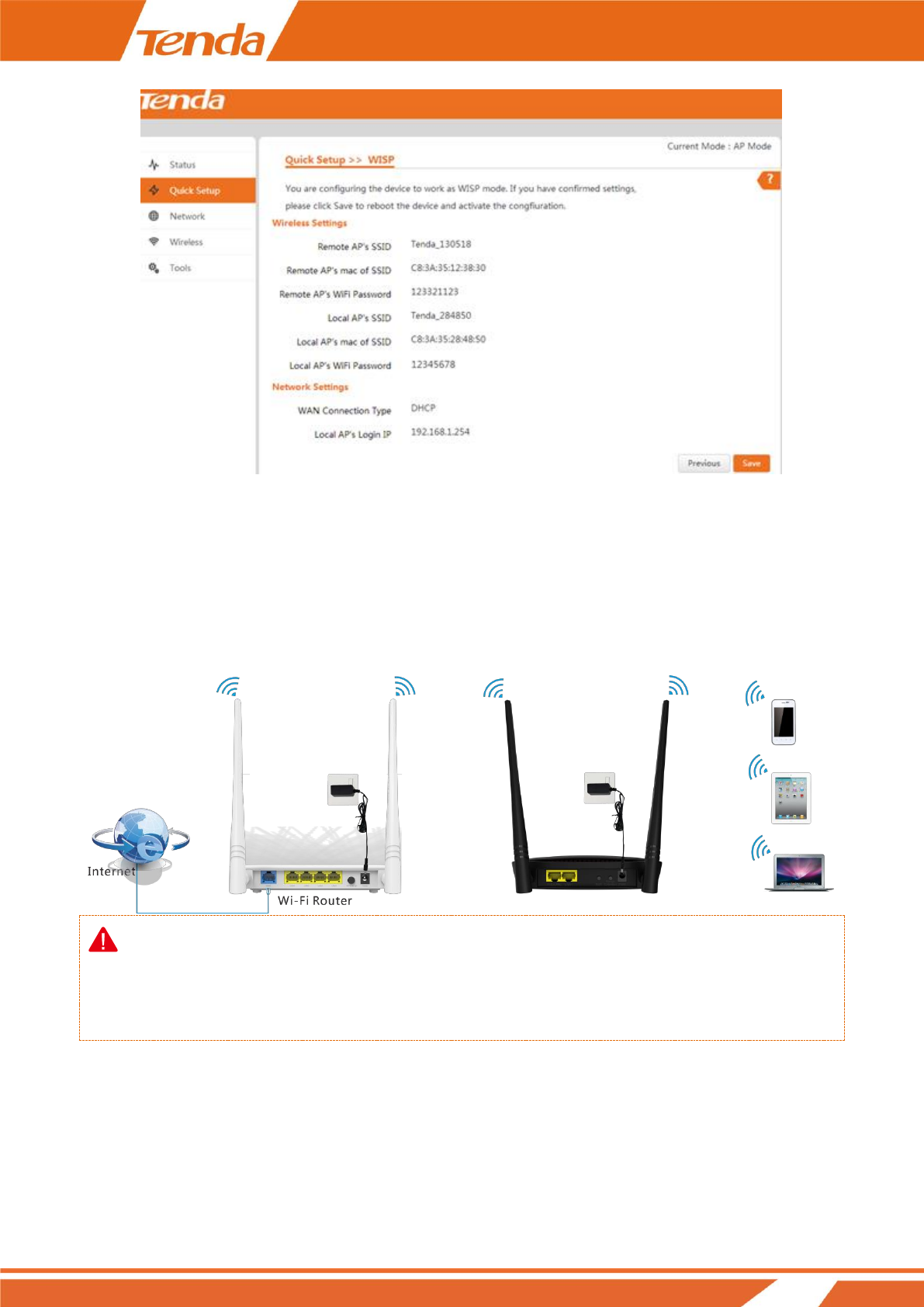
❼ Note down your SSID (WiFi name) and WiFi password on this page and click Save to apply your settings.
Wait until the device restarts successfully.
21
Client + AP Mode
This mode is very similar to universal repeater mode, in which the AP can extend the WiFi range of the uplink
ADSL modem or router by relaying wireless signal. Broadly, the biggest difference between these two modes is
that you can customize your local WiFi name and network security settings in client + AP mode.
Note:
As compatibility problems may exist among routers of different manufacturers, it is not advisable to bridge a
device from other manufacturers.
22
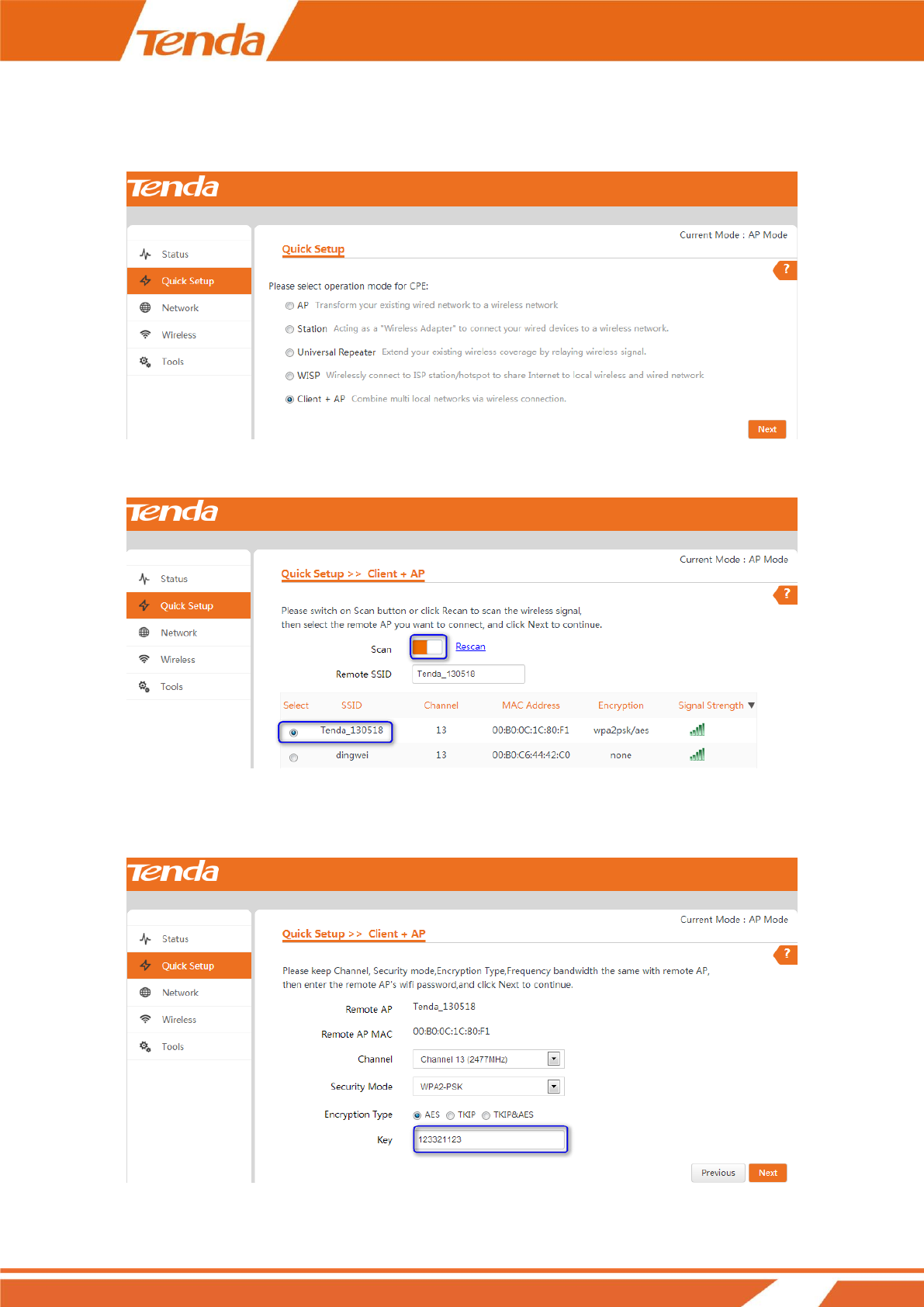
Settings
❶ Select Client +AP mode on Quick Setup page and click Next.
❷ Click the Scan button, select the remote SSID (WiFi name) you wish to and click Next.
❸ The security mode will be selected automatically, please confirm it and enter the WiFi password of the uplink
ADSL modem or router in the Key field and click Next.
23
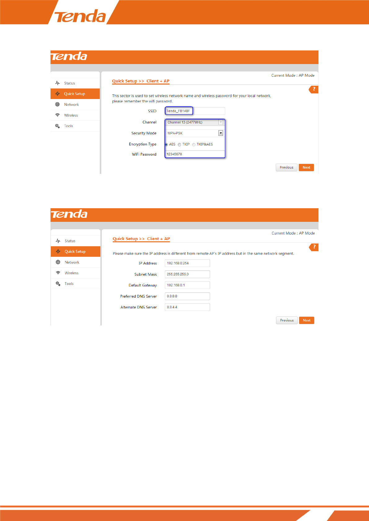
❹ Set the WiFi name and network security settings for your local network and click Next.
❺ Make sure that the IP address is a different one but on the same network segment as that of the uplink ADSL
modem or router and then click Next.
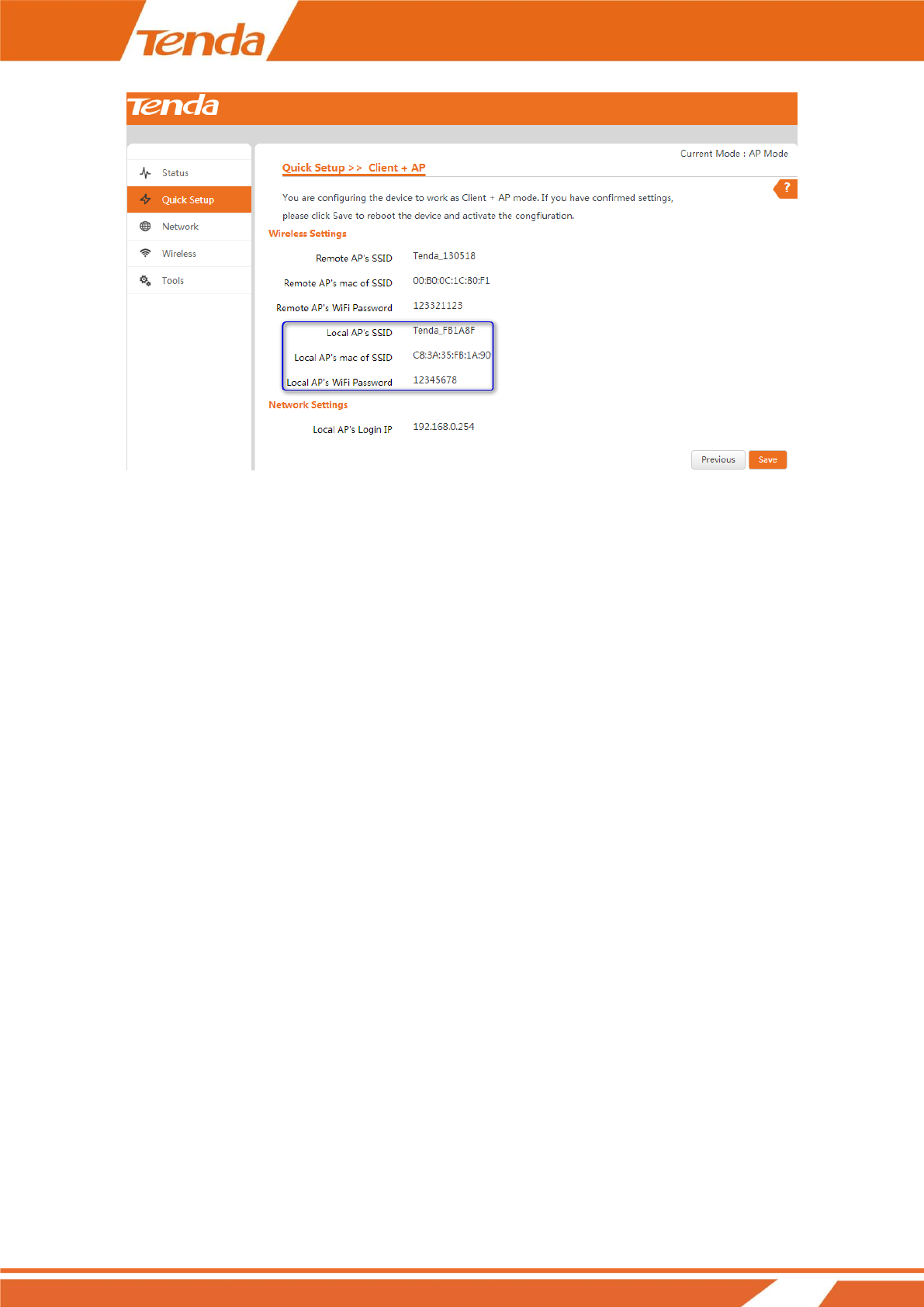
❻ Note down your local SSID (WiFi name) and WiFi password on this page and click Save to apply your
settings. Wait until the device restarts successfully.
24
Step 5: Done!
After finishing settings of the mode you select, set your PC to Obtain an IP address automatically for Internet
access. And your other wireless devices can also connect to it wirelessly for Internet access.
25
3 Setup: Advanced
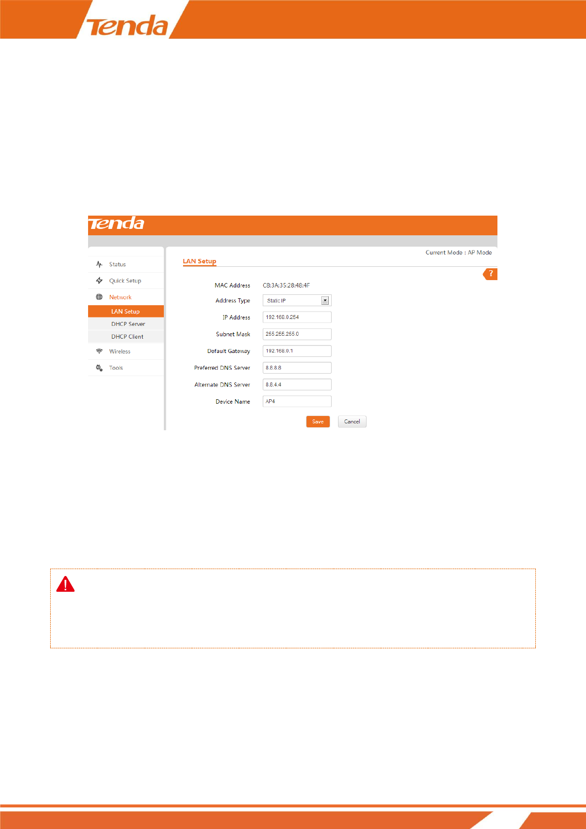
How to Change the LAN IP Address
You can choose whether the AP gets its IP address manually (static IP) or automatically (DHCP). Click Network >
LAN Setup to enter page below:
To set your AP’s IP address in Static IP mode:
❶ Address Type: Select Static IP.
❷ IP Address: Enter a unique IP address that will be used to login to this AP’s web manager.
❸ Subnet Mask: Enter the subnet mask of your network.
❹ Default Gateway: Enter the IP address of the default gateway for your network.
❺ Click Save to apply your changes.
Note:
In static IP address mode, once you’ve changed your LAN IP address, you need to use the new IP address to login
to its web manager.
26
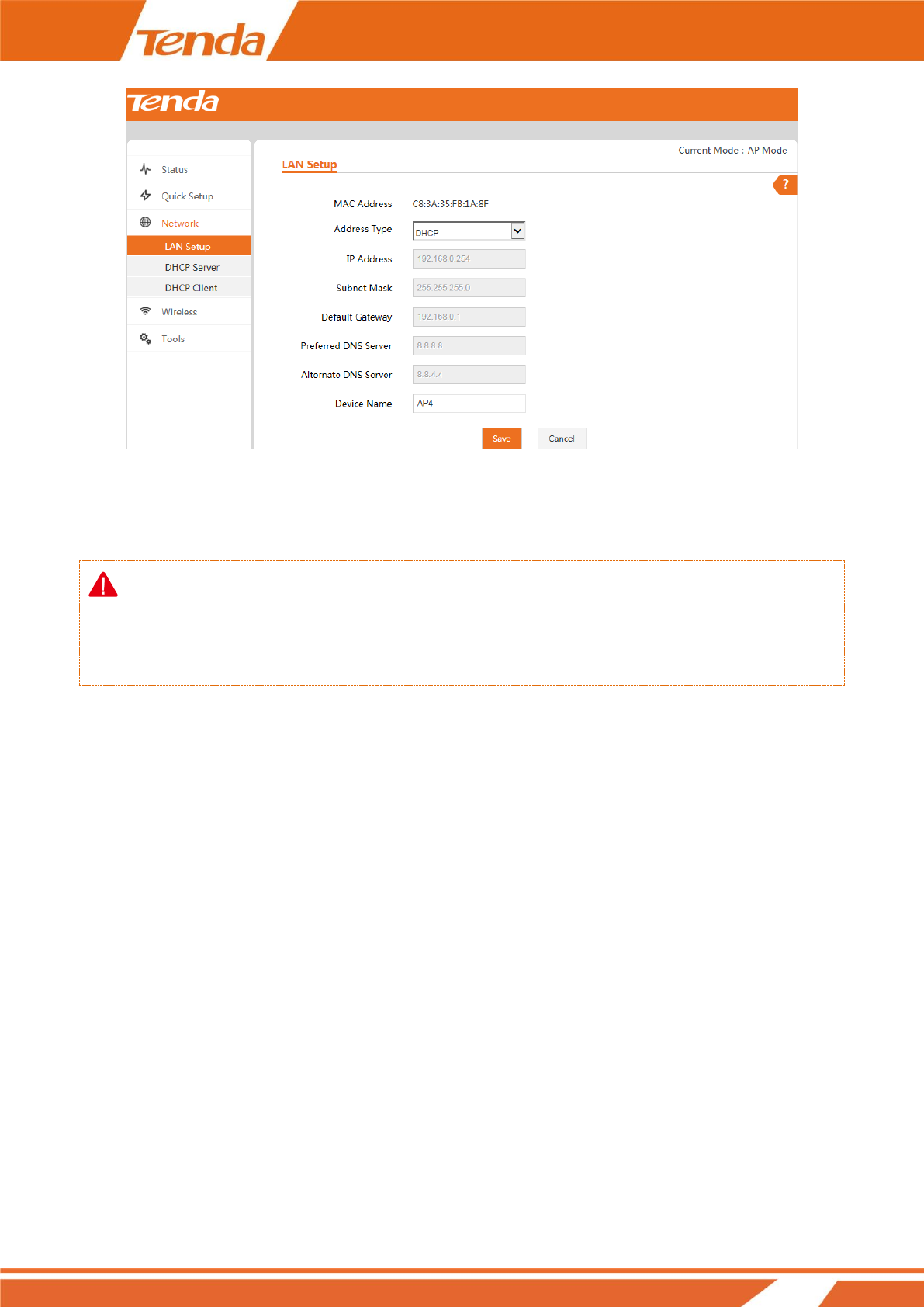
To set your AP’s IP address in DHCP mode:
❶ Address Type: Select DHCP.
❷ Click Save to apply your changes.
Note:
In DHCP mode, your LAN IP address is assigned by the DHCP server of your uplink device. Thus, to know your
LAN IP address, you need to check it on the DHCP client list of the uplink device.
How to Configure DHCP Server Settings
If you enable DHCP server on the device, it will automatically configure the TCP/IP settings for all your LAN
computers (including IP address, subnet mask, gateway and DNS etc.), eliminating the need of manual
intervention. Just be sure to set all computers on your LAN to be DHCP clients by selecting Obtain an IP
Address Automatically respectively on each PC. When turned on, these PCs will automatically load IP
information from the DHCP server. By default, the DHCP server on this device is disabled. The DHCP server will
be enabled while the device is operating in WISP mode. In other modes, you can also enable the DHCP server if
necessary. However, usually, it is not recommended to enable the DHCP server. Click Network > DHCP Server
to enter page below:

27
DHCP Server --- Check/Uncheck it to enable/disable the DHCP server.
Start IP --- The start IP address that the DHCP server has automatically assigned.
End IP --- The end IP address that the DHCP server has automatically assigned.
Primary DNS Server --- Primary DNS server address.
Alternate DNS Server --- Alternate DNS server address.
Lease Time --- How long the IP address can be used by the client device.
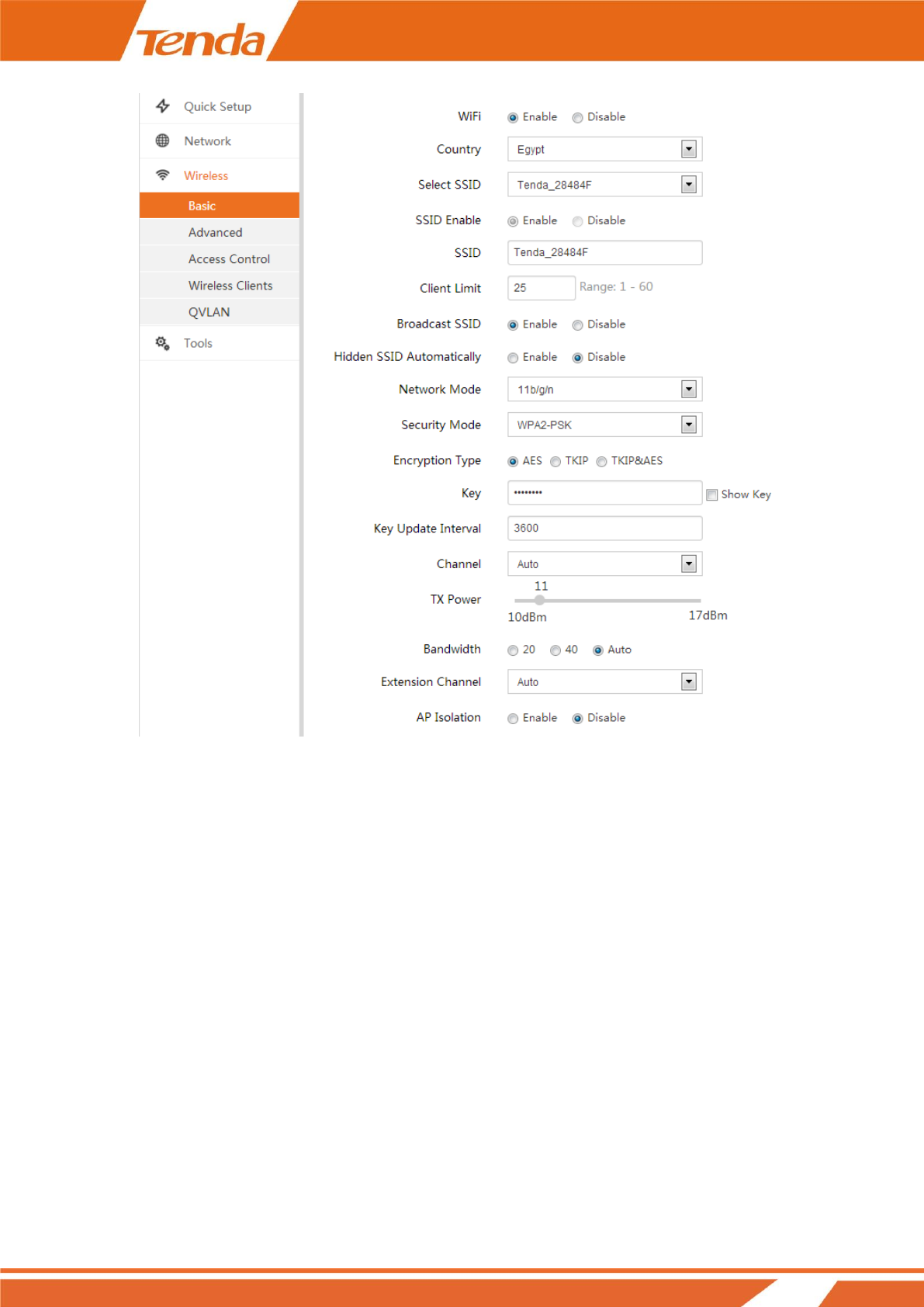
How to Configure Basic Wireless Settings
To configure basic wireless settings, like SSID (WiFi name), network mode, TX power, etc., click Wireless >
Basic to enter page below:
28
WiFi --- Check the Enable box to enable the WiFi of your SSID or check the Disable box to disable the WiFi of
your SSID.
Country --- Select the country for your WiFi.
Select SSID --- Select the SSID you wish to use.
SSID Enable --- Check the Enable box to enable the SSID or check the Disable box to disable the SSID.
SSID --- Customize the SSID as you like.
Client Limit --- Set the maximum number of the clients that can be connected.
Broadcast SSID --- When it is enabled, wireless clients are able to scan the SSID; when it is disabled, wireless
clients are unable to scan the SSID. At this time, if you want to connect to it wirelessly, you have to type in the
SSID and select the encryption mode manually.
Hidden SSID Automatically --- When the maximum number of clients is exceeded, the SSID will be hidden
automatically.

29
Network Mode --- Select a proper network mode: 11 b/g/n mixed, 11 b/g mixed, 11g or 11b.
Security Mode --- Select WEP, WPA-PSK , WPA2-PSK,WPA, WPA2.
(1) WEP: Compliant with the full IEEE 802.11 standard.
Encryption Type: Open, Shared, 802.1 X Enter a WEP key that is either 5 or 13 ASCII characters or 10 or 26 Hex
characters when your encryption type is Open and Shared.
(2) WPA / WPA2 – PSK: A mode based on WPA / WPA2 - PSK.
You can enable personal (PSK) or mixed mode, but you must make sure that the wireless client also supports the
selected encryption method.
Encryption Type: Select AES, TKIP and TKIP & AES.
Key: Enter a security key that is either 8 - 63 ASCII characters or 8 - 64 Hex characters.
(3) WPA/WPA2- Enterprise: A mode based on Radius server authentication.
Radius Server: Display the Radius server's IP address.
Radius Port: Authentication port for Radius server. The default is 1812.
Encryption Type: Select AES, TKIP and TKIP&AES.
Key: Enter a key that is 1-64 ASCII characters.
Key Update Interval --- You can configure security key's update interval here within the range from 60 to 99999
seconds. If set to 0, the key will not be updated.
Channel --- For an optimal wireless performance, you may select the channel with least interference. It is
advisable that you select 'Auto' to let the device detect and select the best possible channel for your wireless
network to operate on.
TX Power --- Define the maximum average transmitted output power (in dBm) of the device. To specify the
output power, use the slider to adjust the output power. Transmitted power regulations differ in different countries.
Bandwidth --- Display the bandwidth of the radio channel. You can use this option to control the bandwidth
occupied by your link.
Extension Channel --- This is used to ensure radio frequency for 802.11n devices on the network.
AP Isolation --- When this function is enabled, wireless clients connected to the same SSID won’t be able to
communicate with each other, which can enhance wireless network security.
30
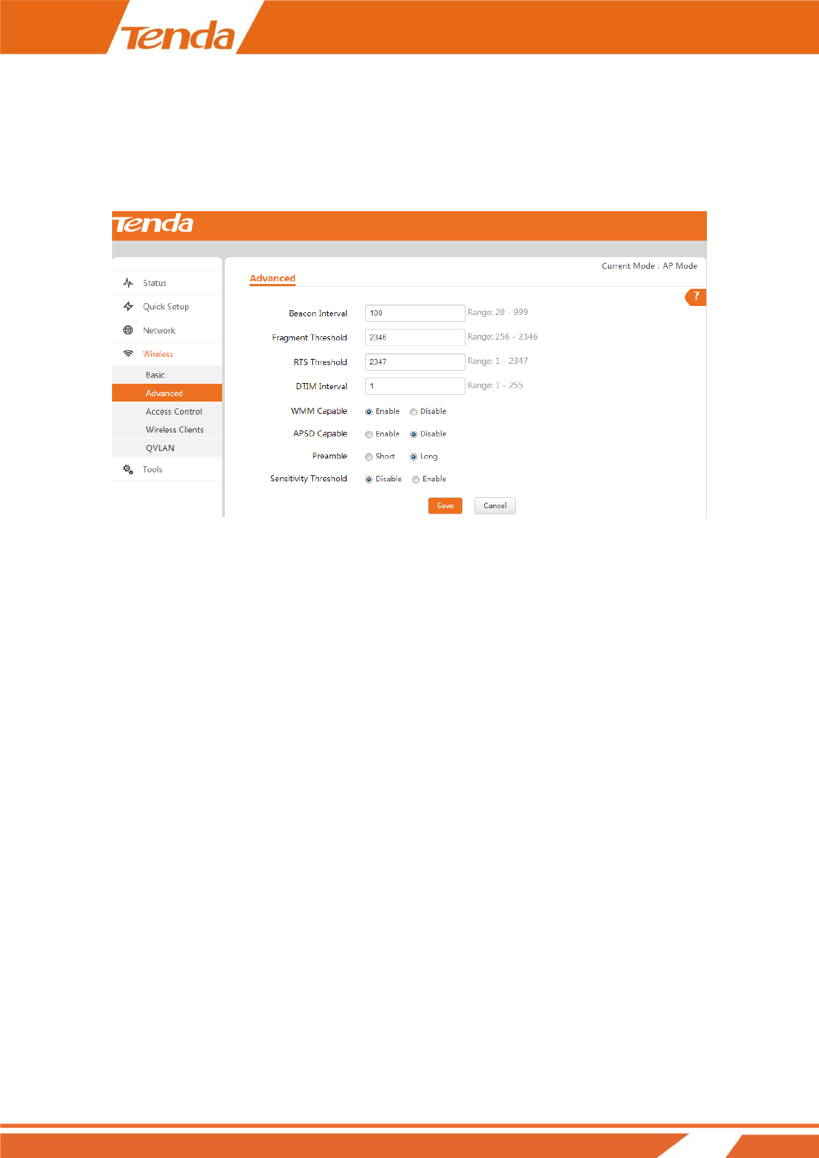
How to Configure Advanced Wireless Settings
Click Wireless > Advanced to configure advanced wireless settings. If you are not familiar with these settings,
keep the default settings unchanged.
Beacon Interval --- This is a time interval between any two consecutive Beacon packets sent by an Access Point
to synchronize a wireless network. Specify a valid value between 20 and 999. The default setting is 100.
Fragment Threshold --- Specify a valid Fragment Threshold value between 255 and 2346. The default is 2346.
Any wireless packet exceeding the preset value will be divided into several fragments before transmission.
RTS Threshold --- Specify a valid value between 1 and 2347. The default is 2347. If a packet exceeds the preset
value, RTS/CTS scheme will be used to reduce collisions. A smaller value is recommended if you have distant
clients or interference on your network.
DTIM Interval --- A DTIM (Delivery Traffic Indication Message) Interval is a countdown informing clients of
the next window for listening to broadcast and multicast messages. When such packets arrive in the router's buffer,
the router will send DTIM (delivery traffic indication message) and DTIM interval to alert clients of the receiving
packets. Specify a valid value between 1 and 255. The default is 1.
WMM Capable --- Enable Wi-Fi Multimedia feature to configure different minimum and maximum waiting
times for the transmission of packets in each queue based on the requirements of the media being sent. Queues
automatically provide minimum transmission delay for Voice, Video, multimedia, and mission critical applications,
and rely on best-effort parameters for traditional IP data.
APSD Capable --- APSD (Automatic Power Save Delivery) is disabled by default.
31
Preamble --- Mainly used for preamble synchronization. It is advisable to keep the default value unchanged.
Sensitivity Threshold --- Define the minimum client signal level accepted by the AP for the client to connect to.
If the client signal level subsequently drops, the client remains connected to the AP.
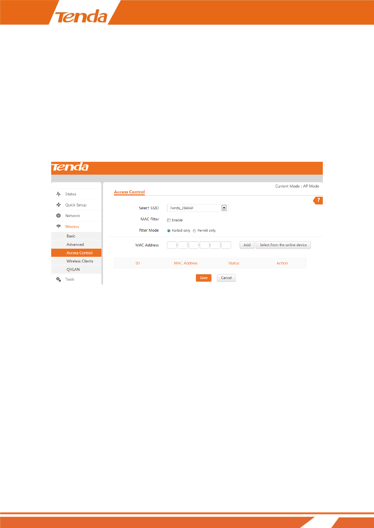
How to Filter Access to Your Network
Click Wireless > Access Control to enter page below. This page allows you to specify a list of devices to allow or
disallow a connection to your wireless network via these devices’ MAC addresses. To deactivate this feature,
uncheck Enable; to activate it, check Enable and select Forbid only or Permit only.
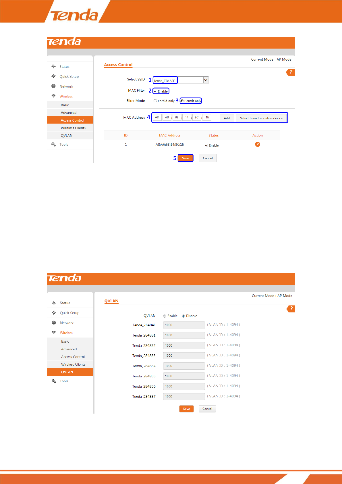
To only allow your computer at the MAC address of the A8:A6:68:14:8C:15 to join your wireless network:
❶ Select the SSID you wish to configure from the drop-down list.
❷ Check the Enable box to enable the MAC Filter feature.
❸ Select Permit only as the Filter Mode.
❹ Enter the MAC address of the device you want to allow, say A8:A6:68:14:8C:15 and click Add. If the MAC
address of the device you wish to control its access has already connected to this AP, you can directly click Select
from the online device to add its MAC address.
❺ Click Save to apply your changes.
32
How to Configure QVLAN Settings to Work with
Switches
QVLAN enables this AP to broadcast up to 8 wireless networks with different names. When using this feature,
users could also assign different VLAN IDs to different wireless networks, which makes it possible to get it work
with switches which as VLAN assigned for different access levels and authorities. The QLAN feature is only
configurable in AP mode.
33
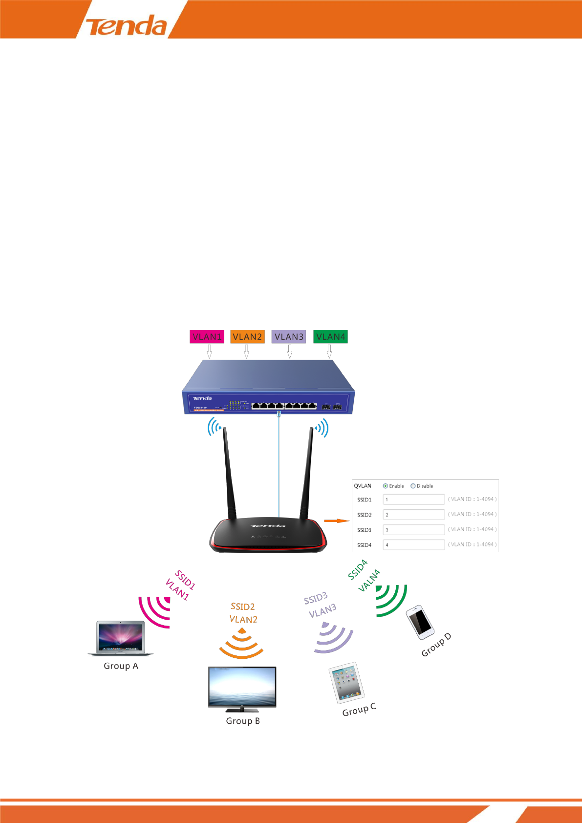
Below is a basic topology of How AP4 should work with Switches that has VLAN assigned. Assume that in the
network there are four Departments: HR, Sales, Technical and R&D. They belong to different VLAN networks to
have different authorities (HR-VLAN1, Sales-VLAN2, Tech-VLAN3, and R&D-VLAN4). When we setup VLAN
to each SSID, for example:
SSID 1 with VID 1;
SSID 2 with VID 2;
SSID 3 with VID 3;
SSID 4 with VID 4;
Then Group A, B, C, D will only have access to its related VLAN resources. Take Group A as an example, the
clients are connecting to SSID 1, so these people would only have access to the HR department’s resources. (The
Access authority of different VLANs (VLAN1, VLAN2, VLAN3, VLAN4) is already configured on the Switch.)
34
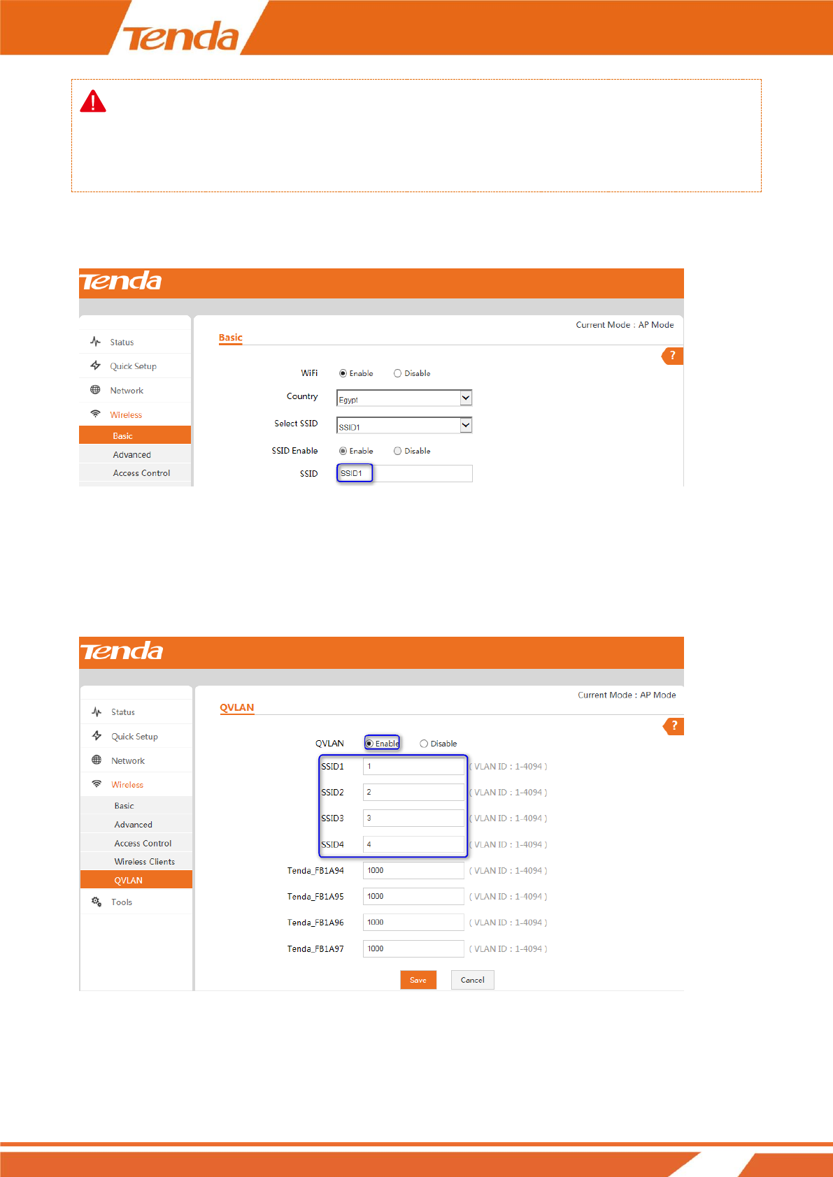
Note
Only the PoE/LAN2 port is QVLAN-enabled. Thus, to enable QVLAN feature on this AP, you need to connect
the PoE/LAN2 port on the AP to the switch.
Settings on AP4:
❶ Click Wireless > Basic to set 4 SSIDs: SSID1, SSID2, SSID3 and SSID4.
❷ Click Wireless > QVLAN and select the Enable option to enable the QVLAN feature on AP4.
❸ Set SSID1 with VLAN ID 1, SSID2 with VLAN ID 2, SSID3 with VLAN ID 3 and SSID4 with VLAN ID 4
as shown below:
❹ Click Save to apply your changes.
35
How to Login to Web Manager in a More Secure
Way
Tip
When HTTP and HTTPS web service are enabled simultaneously, you are only allowed to login to its web
manager via HTTPS.
How to login to Web Manager via HTTP
To login to its web manager via HTTP:
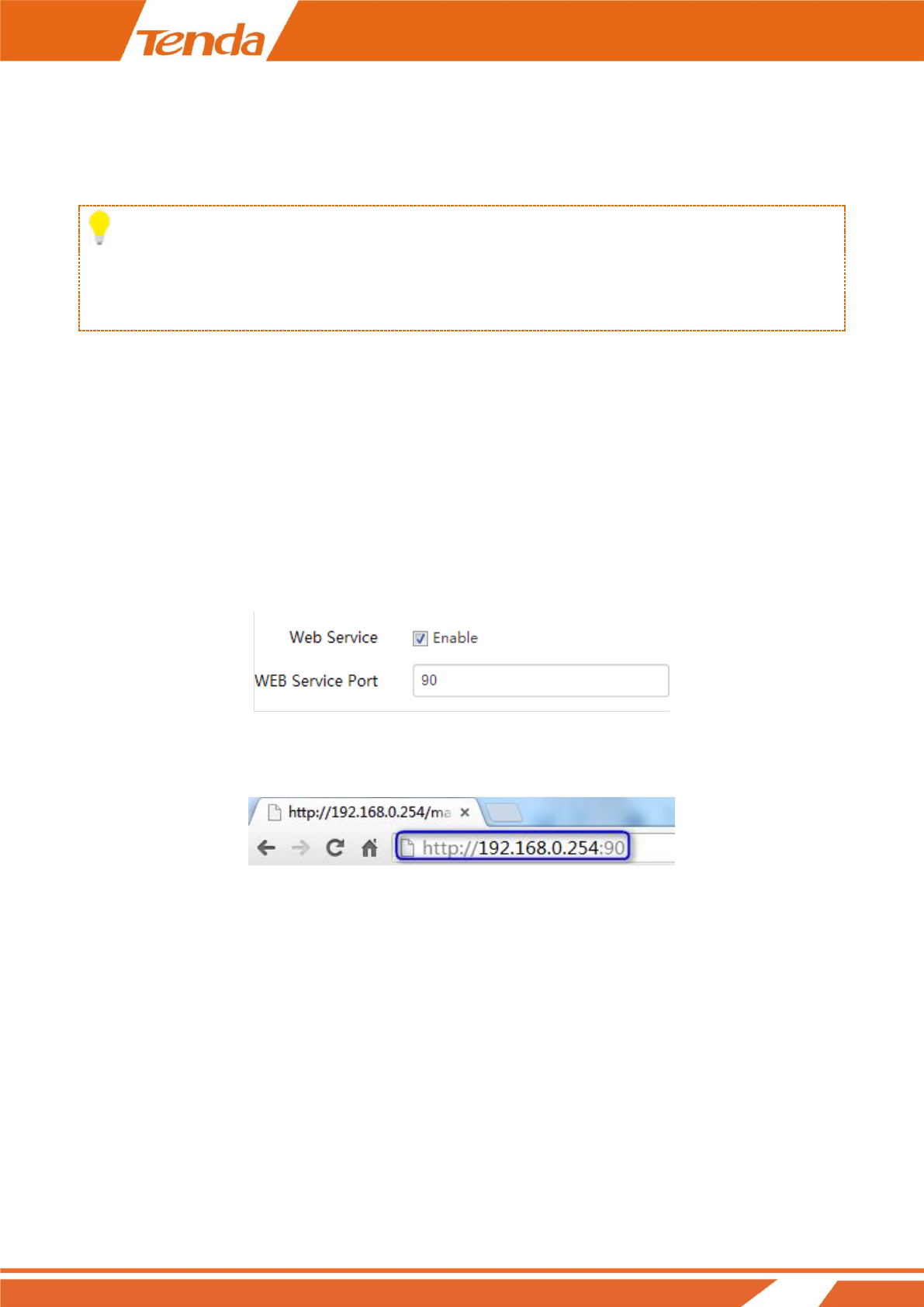
❶ Click Tools > Network Service and locate the HTTP web service feature.
❷ Check the Enable box to enable HTTP web service feature.
❸ Enter the HTTP web service port. By default, it is port 80.
❹ Click Save at the bottom of this page to apply your changes.
❺ Then you need to enter “http://login IP address: port No.” in the address bar to login to its web manager.
Here we enter “http://192.168.0.254:90” in the address bar.
How to login to Web Manager via HTTPS
To login to its web manager via HTTPS:
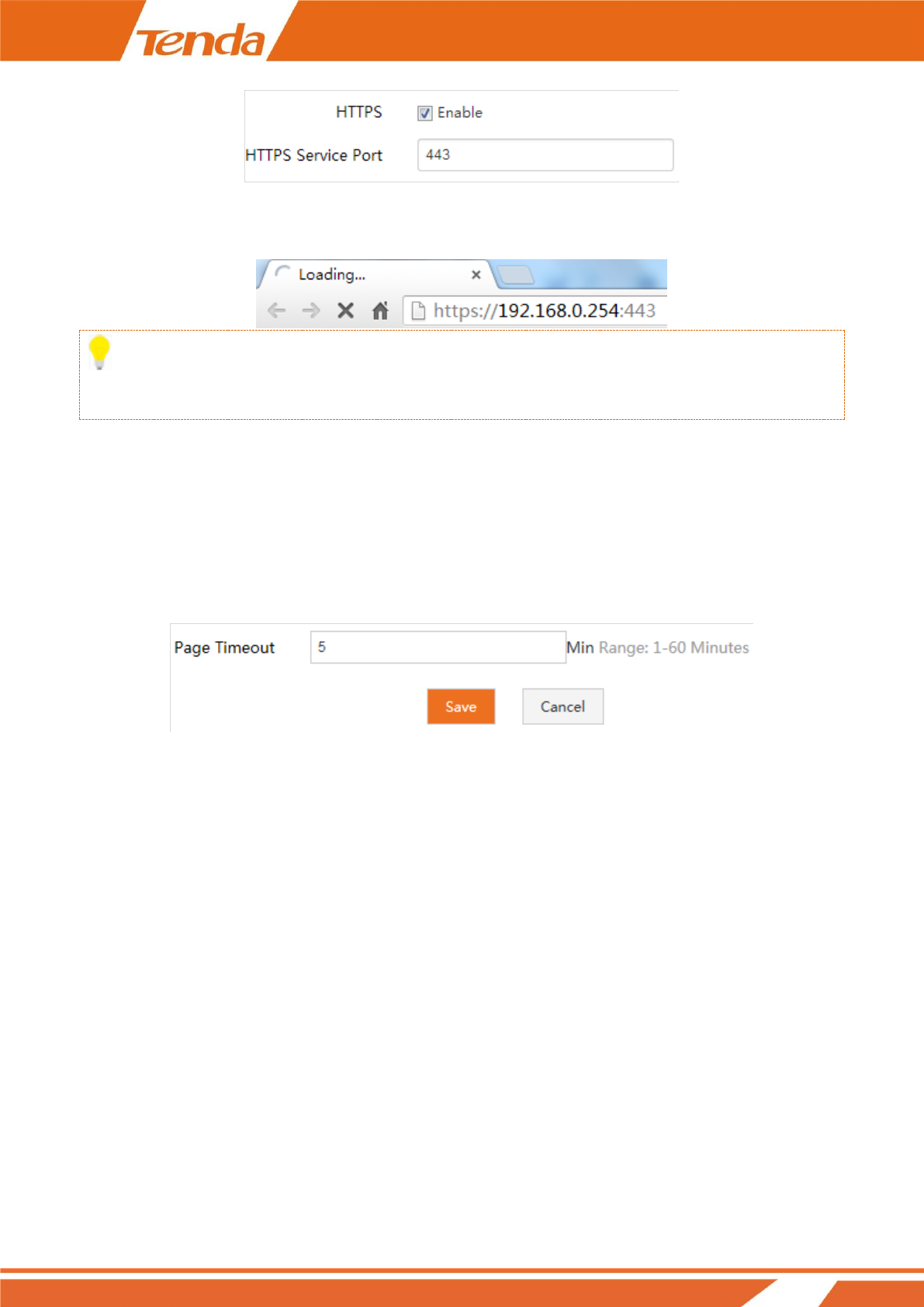
❶ Click Tools > Network Service and locate the HTTPS web service feature.
❷ Check the Enable box to enable HTTPS web service feature.
❸ Enter the HTTP web service port. By default, it is port 443.
❹ Click Save at the bottom of this page to apply your changes.
36
❺ Then you need to enter “https://login IP address: port No.” in the address bar to login to its web manager.
Here we enter “https://192.168.0.254:443” in the address bar.
Tip:
HTTPS web service is a more secure way for web login.
How to Configure the Idle Timeout
You are automatically logged out of the web manager after a period of inactivity. You can set the length of the
inactive period. To change the page idle timeout, click Tools > Network Service, locate the Page Timeout field,
set the page timeout you wish to and click Save.
How to Configure System Time for Your Device
This section assists you in setting the device's current time; you can select to either set the time and date manually
or obtain the GMT time from the Internet automatically. System time can be configured using the following 2
methods:
Synchronized with the Internet: If enabled, system automatically connects to NTP server on the Internet to
synchronize the time.
Manual: Specify the time and date manually or click Synchronized with local time to automatically copy your
current PC's time to the device.
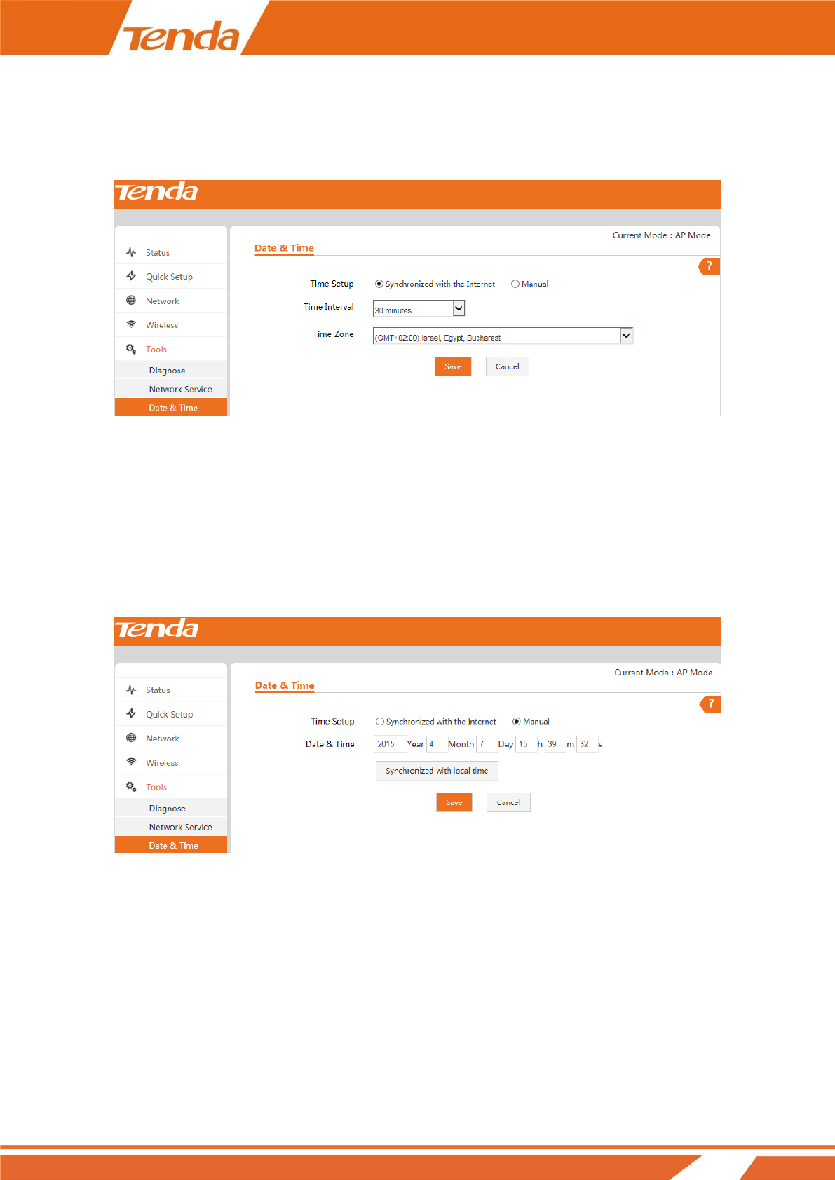
To Sync with Internet time servers:
❶ Click Tools > Date & Time.
❷ Select Synchronized with the Internet.
37
❸ Select a time interval from the drop-down list.
❹ Select your time zone.
❺ Click Save.
To set time and date manually:
❶ Click Tools > Date & Time.
❷ Select Manual.
❸ Specify the time and date manually or click Synchronized with local time to automatically copy your PC's
time to the device.
❹ Click Save.
And then go to the Status page to make sure that the system time is correctly updated.
How to Change the Login User Name and
Password
Click Tools > Administrator to enter screen below. Here you can change the user name and password for web
login. We suggest that you change this password to a more secure one.

38
39
4 Maintaining and Monitoring
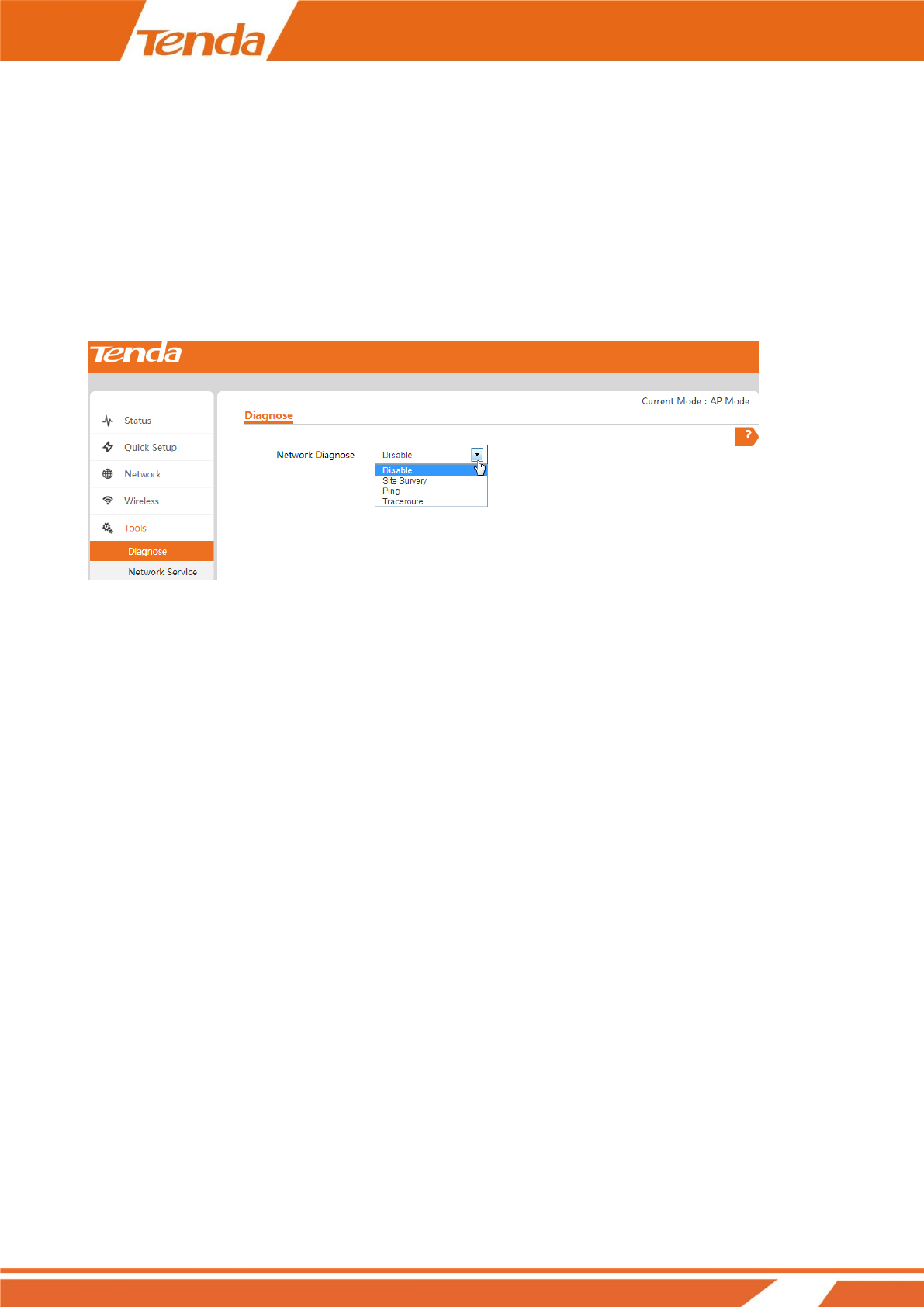
How to Diagnose Your Network
Three ways are available here to diagnose your network. If there’s something wrong with your network, select the
proper one as you need. To deactivate this feature, select Disable.
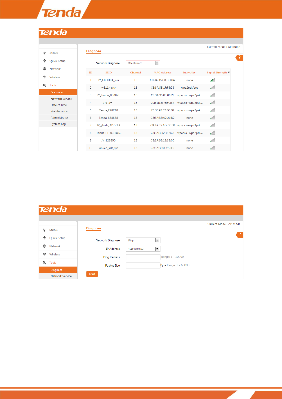
Site Survey
To get an overview of your nearby wireless networks in range on all supported channels, click Tools > Diagnose
and then select Site Survey.
The Site Survey tool reports the SSID, MAC Address, Channel, Security Mode, Encryption Type, Signal Strength
of each AP in the surrounding environment.
40
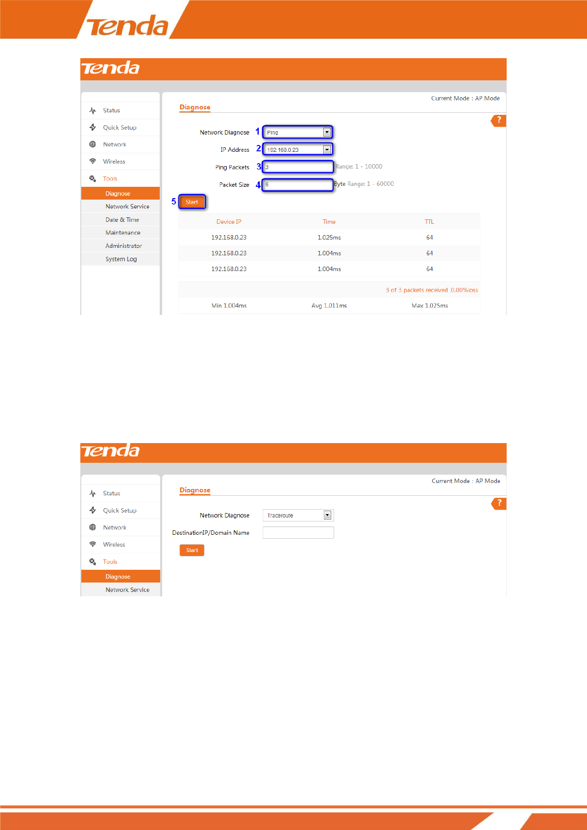
Ping
Ping is a computer network administration utility used to test the reachability of a host on an Internet Protocol (IP)
network and to measure the round-trip time for messages sent from the original host to a destination computer.
To implement Ping action, click Tools > Diagnose and finish settings as shown below:
❶ Select Ping from the Network Diagnose drop-down menu.
❷ Select an IP address you wish to diagnose or select Manual to enter the IP or domain name manually.
❸ Set the number of Ping packets within the range from 1 to 10000.
❹ Set the packet size within the range from 1 to 60000.
❺ Click Start to Ping the network.
Then you can view the Ping info below.
41
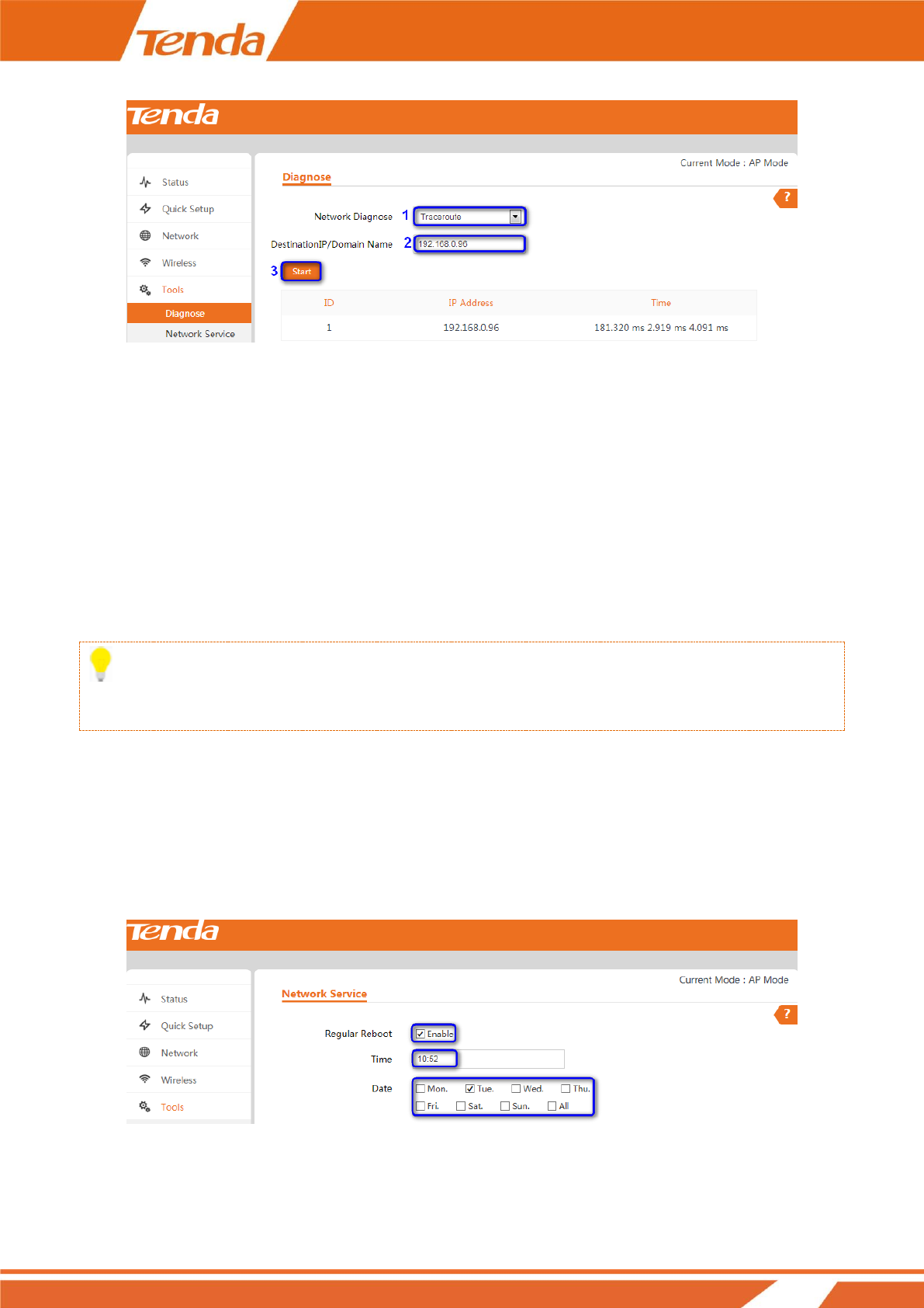
Traceroute
Traceroute is a computer network diagnostic tool for displaying the route (path) and measuring whether network
connection is available or not. When malfunctions occur to the network, you can locate trouble spot of the
network with this traceroute test.
To implement Traceroute action, click Tools > Diagnose and finish settings as shown below:
❶ Select Traceroute from the Network Diagnose drop-down menu.
❷ Enter the destination IP or domain name of the destination host.
❸ Click Start to traceroute the network.
Then you can view the traceroute info below.
42
How to Reboot Your AP
When some settings you have configured cannot be activated or your device is functioning improperly, you can
reboot your device. Once this function is enabled, please make sure that your device is synchronized with the
Internet time server.
Reboot Regularly
Tip
To activate this feature, verify that you have synchronized the device’s system time with the Internet or your PC.
To reboot your device regularly and automatically, follow steps below:
❶ Click Tools > Network Service.
❷ Check the Enable box of Regular Reboot.
❸ Set the date (from Monday to Sunday) to regular reboot your device.
❹ Click Save at the bottom of this page to apply your changes.
43
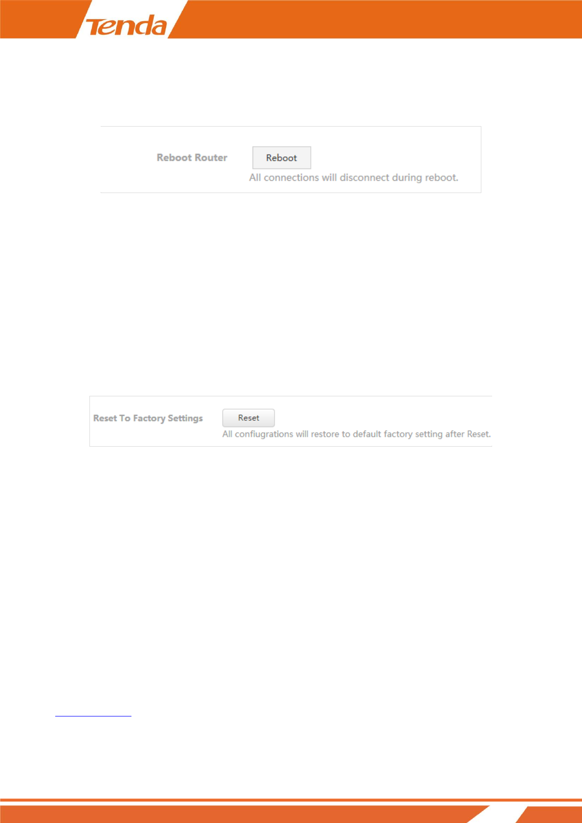
Reboot Manually
To reboot your device manually, click Tools > Maintenance, locate the Reboot Router section and click Reboot.
How to Reset Your AP
If the device or client connected to the device fails to access the Internet due to incorrect configurations and you
cannot solve the problem, you can reset the device. once you reset your AP, all your current settings will be lost
and you need to reconfigure it.
To reset your AP, two methods are available:
Method 1: Via Web manager
Click Tools > Maintenance, locate the Reset to Factory Settings and click Reset.
Method 2: Via the hardware RST button
Pressing the RST button for over 7 seconds restores this device to its factory defaults.
Factory Default Settings:
User Name: admin
Password: admin
IP Address: 192.168.0. 254
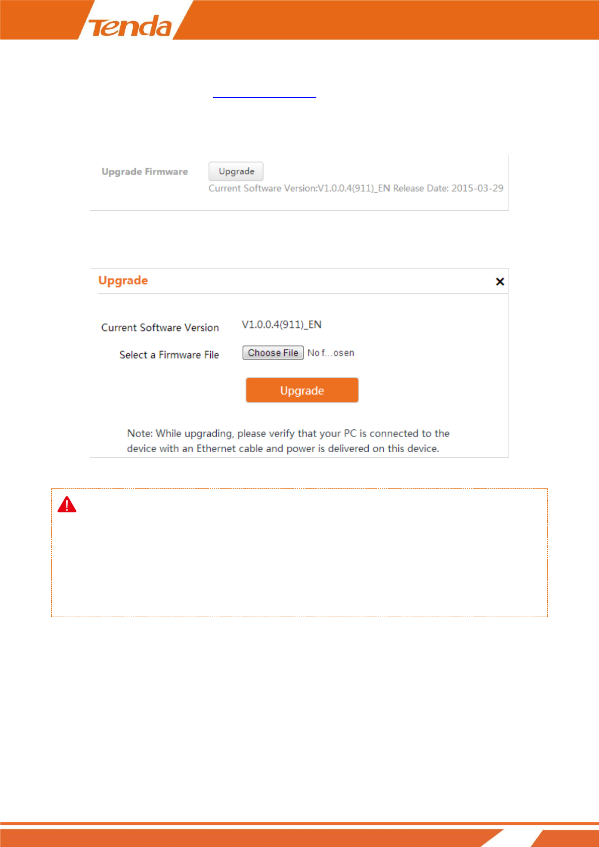
How to Upgrade Your AP
If your device is in normal operation, it is not advisable to upgrade your device. If you want to acquire the latest
software version or better value-added functions for your device, you can access our official website
www.tendacn.com to download the latest software for upgrading.
44
To upgrade your AP:
❶ Launch a web browser and go to http://www.tendacn.com to download the latest firmware.
❷ Unzip the compressed upgrade file in the corresponding directory.
❸ Click Tools > Maintenance, locate the Upgrade Firmware section and click Upgrade.
❹ Click Choose File (in Google browser) to locate and select the upgrade file in the corresponding directory on
your hard disk.
❺ Click Upgrade.
Note
1. While upgrading, please verify that your PC is connected to the device with an Ethernet cable and power is
delivered on this device. And the upgrading process will take several minutes, please be patient.
2. When the upgrading is completed, your device will be restored to factory default settings automatically and
you need to reconfigure your device.
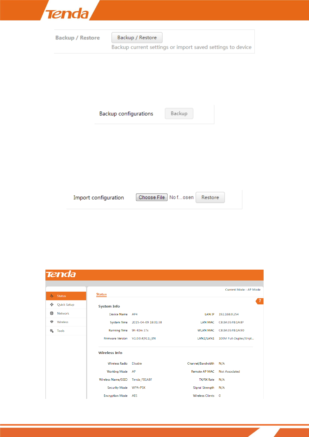
How to Backup and Restore Your AP’s Configurations
If you configure many settings on this device, which will make this device work in good status and suitable
environment, it’s suggested to backup settings for this device, which will be convenient for troubleshooting and
saving time for next time’s configuration. Click Tools > Maintenance and locate the Backup/Restore section.
45
To backup your configurations:
❶ Click Backup / Restore.
❷ Click Backup on the pop-out window and follow on screen instructions to save your configurations in a
directory on your hard disk.
To restore your configurations:
❶ Click Backup / Restore.
❷ Click Choose File (in Google browser) to load configuration files which you have stored on your hardware
disk previously.
❸ Click Restore.
How to View System Info and Wireless Info of Your
AP
To view system information and wireless information of this device, click Status to enter page below:
46
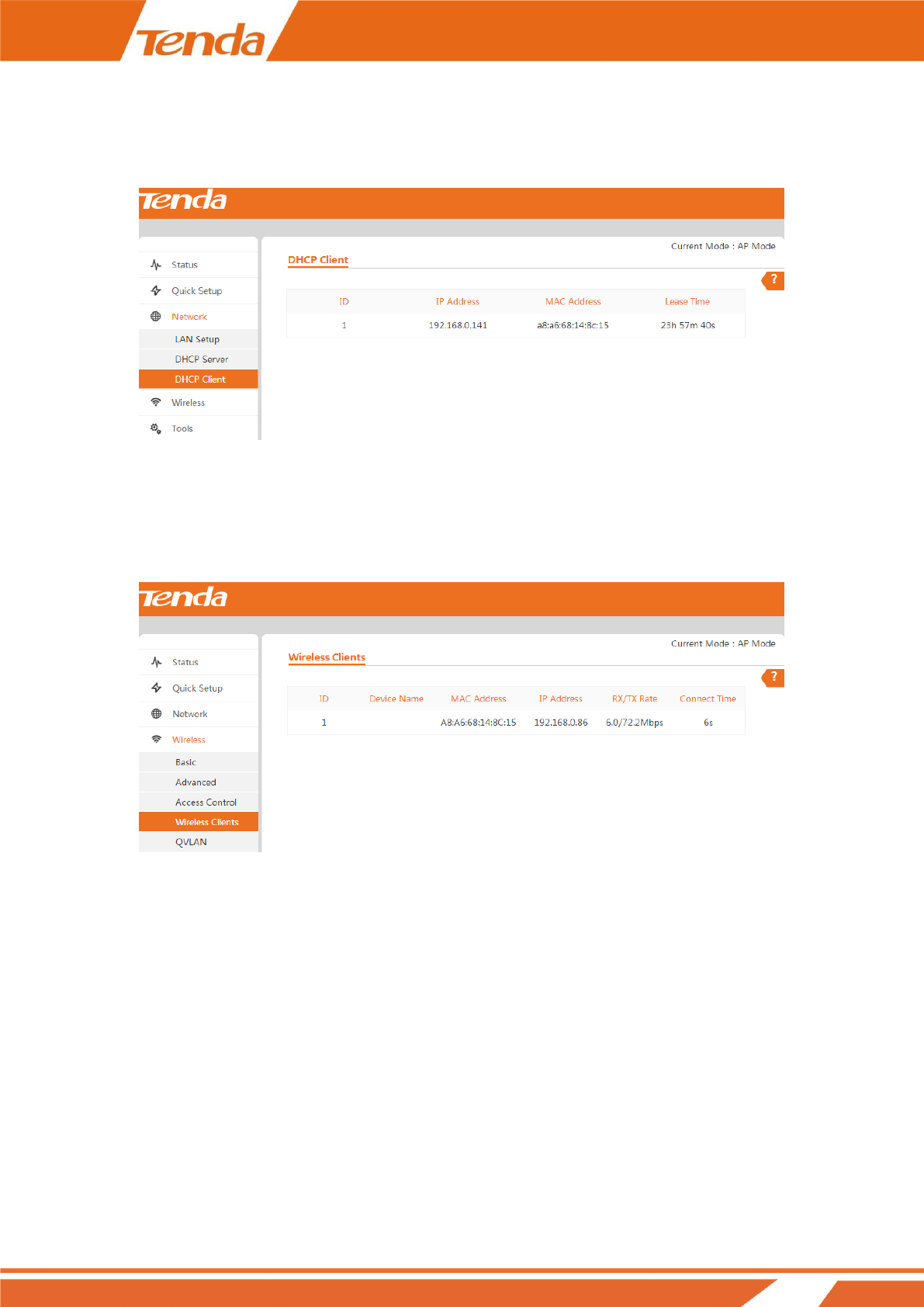
How to View DHCP Client Information
To view DHCP clients information, click Network > DHCP Client to enter page below:
How to View Wireless Clients Information
To view wireless clients information, click Wireless > Wireless Clients to enter page below:
How to View the History of Your AP’s Actions
Click Tools > System Log to enter screen below. Here you can view the history of the device’s actions. Three
types of logs are supported on this device: All, System and WAN. You can select any one of them from the
drop-down list. Click Refresh to update current log info or click Clear to clear all logs.

47
48
Appendix
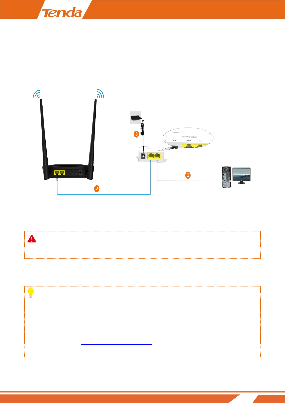
A With PoE Setup
❶ Connect your computer to the LAN port of the injector with the included Ethernet cable.
❷ Connect the PoE/LAN2 port of your AP to the PoE port of the injector with another Ethernet cable.
❸ Plug the included power adapter into the DC jack of the injector, and the other end to a nearby power outlet.
Note:
The PoE injector supports a maximum cable (Cat5e or better) length of up to 35 meters (115 feet or so).
B Connect to Your WiFi
Tip
1. The PC you use must have an installed wireless network adapter.
2. The device's SSID is "Tenda_XXXXXX" by default (where "XXXXXX" is the last six characters of its MAC
address). You can find the MAC address and SSID on the label attached to the device’s bottom).
3. The first time you connect to your WiFi to configure the AP, you need to set your PC to Use the following IP
address. For details, see Step 2: Configure IP on Your PC . After finishing configuring the AP, you need to
re-connect to your WiFi and set your PC to Obtain an IP address automatically for Internet access.
49
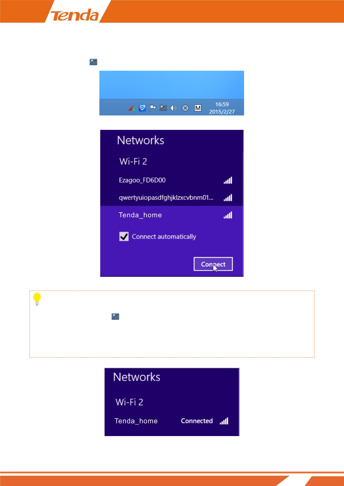
Windows 8
Step 1: Click the icon on the bottom right corner of your desktop.
Step 2: Select your wireless network from the list, click Connect and then follow onscreen instructions.
Tip
1. If you cannot find the icon , please move your mouse to the top right corner of your desktop, select
Settings > Control Panel > Network and Internet > Network and Sharing Center > Change adapter
settings, right click Wi-Fi and select Connect/Disconnect.
2. If you cannot find your wireless network from the list, ensure the Airplane Mode is not enabled on your PC.
Step 3: When your wireless network is connected successfully, the following screen will appear.
50
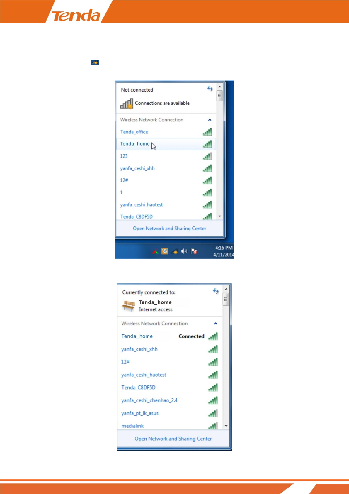
Windows 7
Step 1: Click the icon on the bottom right corner of your desktop.
Step 2: Double click your SSID (wireless network name) and then follow onscreen instructions.
Step 3: When your SSID (wireless network name) displays Connected as shown below, you’ve connected to it
for Internet access successfully.
51
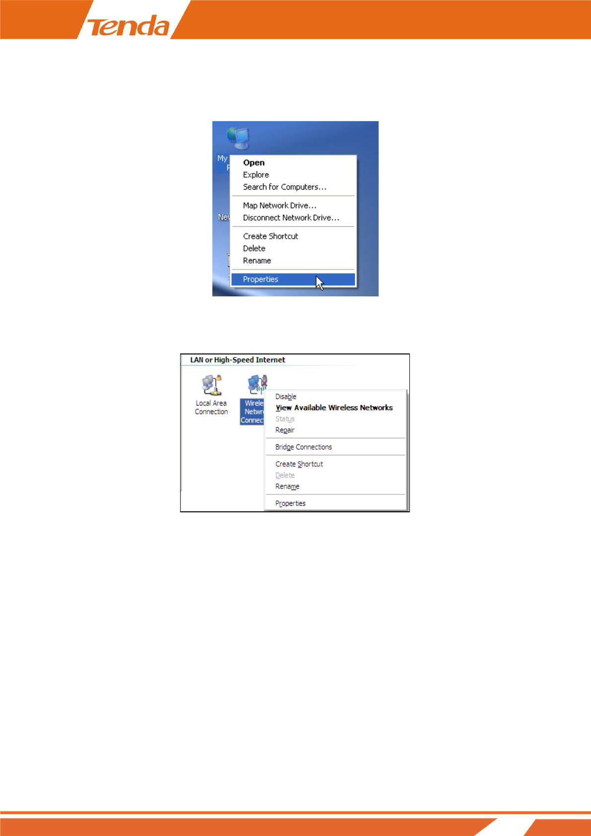
Windows XP
Step 1: Right click My Network Places, and select Properties.
Step 2: Right click Wireless Network Connection, and select View Available Wireless Networks from the
pop-up submenu.
Step 3: Select your wireless network from the list and then follow onscreen instructions.
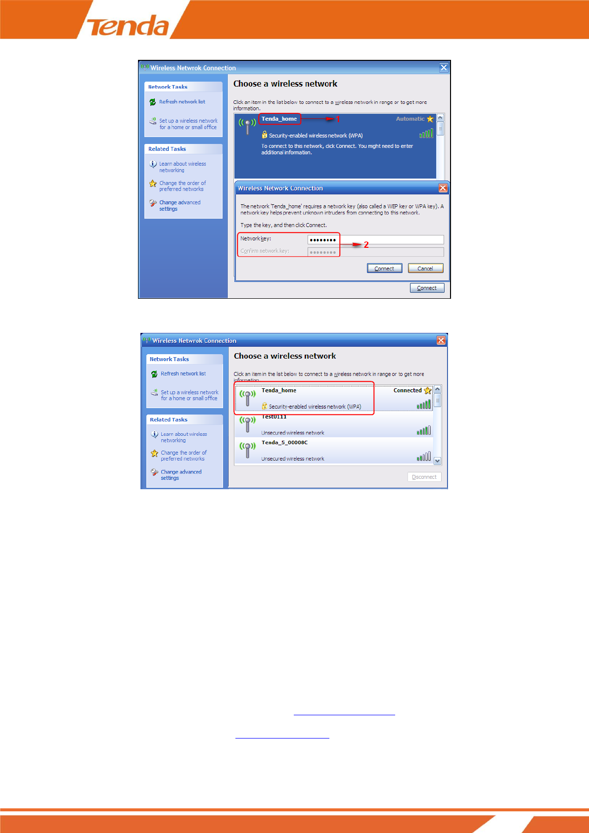
52
Step 4: When your SSID displays Connected as shown below, you’ve connected to it successfully.
C FAQs
Q: I enter the device’s LAN IP address in the web browser but cannot access this device’s web manager.
What should I do?
1) Verify that the IP address of computer should be a different one but on the same network segment as the LAN
IP address of devices. The default LAN IP address of AP is 192.168.0.254 and you need to set your PC to a static
IP address within the following range: 192.168.0.X (2~253);
2) Clear the browser cookies or try another web browser;
If you are still unable to login, please refer to section How to Reset Your AP to restore the device to factory
default settings and follow steps in section 2 Quick Internet Setup to configure your settings again.

53
D Safety & Emission Statement
CE Mark Warning
This is a Class B product. In a domestic environment, this product may cause radio interference, in which case the
user may be required to take adequate measures. This device complies with EU 1999/5/EC.
NOTE: (1) The manufacturer is not responsible for any radio or TV interference caused by unauthorized
modifications to this equipment. (2) To avoid unnecessary radiation interference, it is recommended to use a
shielded RJ45 cable.
FCC Statement
This device complies with Part 15 of the FCC Rules. Operation is subject to the following two conditions: (1) This
device may not cause harmful interference, and (2) this device must accept any interference received, including
interference that may cause undesired operation.
This equipment has been tested and found to comply with the limits for a Class B digital device, pursuant to Part
15 of the FCC Rules. These limits are designed to provide reasonable protection against harmful interference in a
residential installation. This equipment generates, uses and can radiate radio frequency energy and, if not installed
and used in accordance with the instructions, may cause harmful interference to radio communications. However,
there is no guarantee that interference will not occur in a particular installation. If this equipment does cause
harmful interference to radio or television reception, which can be determined by turning the equipment off and
on, the user is encouraged to try to correct the interference by one of the following measures:
— Reorient or relocate the receiving antenna.
— Increase the separation between the equipment and receiver.
— Connect the equipment into an outlet on a circuit different from that to which the receiver is connected.
— Consult the dealer or an experienced radio/TV technician for help.
FCC Caution: Any changes or modifications not expressly approved by the party responsible for compliance
could void the user's authority to operate this equipment.
This transmitter must not be co-located or operating in conjunction with any other antenna or transmitter.
The manufacturer is not responsible for any radio or TV interference caused by unauthorized modifications to this

54
equipment.
Radiation Exposure Statement
This equipment complies with FCC radiation exposure limits set forth for an uncontrolled environment. This
equipment should be installed and operated with minimum distance 20cm between the radiator & your body.
NOTE: (1) The manufacturer is not responsible for any radio or TV interference caused by unauthorized
modifications to this equipment. (2) To avoid unnecessary radiation interference, it is recommended to use a
shielded RJ45 cable.