TENDA TECHNOLOGY D152 Wireless N150 ADSL2+ Modem Router User Manual
SHENZHEN TENDA TECHNOLOGY CO., LTD. Wireless N150 ADSL2+ Modem Router
User Manual
Wireless Modem Router User Guide
-1 -

Wireless Modem Router User Guide
-2 -
Copyright Statement
is the registered trademark of Shenzhen Tenda Technology Co., Ltd. All the products and product names
mentioned herein are the trademarks or registered trademarks of their respective holders. Copyright of the whole product
as integration, including its accessories and software, belongs to Shenzhen Tenda Technology Co., Ltd. No part of this
publication can be reproduced, transmitted, transcribed, stored in a retrieval system, or translated into any language in
any form or by any means without the prior written permission of Shenzhen Tenda Technology Co., Ltd.
All photos and product specifications mentioned in this manual are for references only. Upgrades of software and
hardware may occur; Tenda reserves the right to revise this publication and to make changes in the content hereof
without obligation to notify any person or organization of such revisions or changes. If you would like to know more
about our product information, please visit our website at http://www.tendacn.com.

Wireless Modem Router User Guide
-3 -
Table of Contents
COPYRIGHT STATEMENT ........................................................................................................................................ - 2 -
ABOUT THIS MANUAL .............................................................................................................................................. - 5 -
CHAPTER1 GET TO KNOW YOUR WIRELESS ROUTER ................................................................................. - 6 -
PRODUCT FEATURES ..................................................................................................................................................... - 6 -
PACKAGE CONTENTS .................................................................................................................................................... - 7 -
CHAPTER 2 HARDWARE INSTALL ....................................................................................................................... - 8 -
Front Panel ............................................................................................................................................................... - 8 -
Back Panel ............................................................................................................................................................... - 9 -
CHAPTER 3 QUICK INTERNET SETUP ............................................................................................................... - 10 -
3.1 LOG IN TO WEB MANAGER ................................................................................................................................... - 10 -
Using Setup Wizard ............................................................................................................................................... - 10 -
Using Browser ....................................................................................................................................................... - 11 -
2.2 INTERNET SETUP ................................................................................................................................................... - 12 -
2.3 QUICK WIRELESS SECURITY SETUP ...................................................................................................................... - 13 -
CHAPTER 4 ADVANCED SETTINGS ..................................................................................................................... - 14 -
4.1 DEVICE INFO ......................................................................................................................................................... - 15 -
4.2 ADVANCED SETUP ................................................................................................................................................. - 18 -
4.2.1 Layer2 Interface ............................................................................................................................................ - 19 -
4.2.2 WAN Service ................................................................................................................................................. - 21 -
4.2.3 LAN Setup .................................................................................................................................................... - 54 -
4.2.4 NAT ............................................................................................................................................................... - 56 -
4.2.5 Security ......................................................................................................................................................... - 61 -
4.2.6 Parental Control ............................................................................................................................................ - 64 -
4.2.7 Quality of Service ......................................................................................................................................... - 66 -
4.2.8 Routing .......................................................................................................................................................... - 69 -
4.2.9 DNS ............................................................................................................................................................... - 71 -
4.2.10 DSL ............................................................................................................................................................. - 73 -
4.2.11 UPnP ........................................................................................................................................................... - 75 -
4.1.12 Interface Grouping ...................................................................................................................................... - 75 -
4.1.13 IP Tunnel ..................................................................................................................................................... - 77 -
4.1.14 Certificate .................................................................................................................................................... - 78 -
4.1.15 Multicast ..................................................................................................................................................... - 81 -
4.1.16 IPTV ............................................................................................................................................................ - 83 -
4.3 WIRELESS ............................................................................................................................................................. - 84 -
4.3.1 Basic .............................................................................................................................................................. - 84 -
4.3.2 Security ......................................................................................................................................................... - 85 -
4.3.3 MAC Filter .................................................................................................................................................... - 86 -
4.3.4 Wireless Bridge ............................................................................................................................................. - 87 -
4.3.5 Station Info .................................................................................................................................................... - 88 -
4.4 DIAGNOSTICS ........................................................................................................................................................ - 88 -

Wireless Modem Router User Guide
-4 -
4.5 MANAGEMENT ...................................................................................................................................................... - 89 -
4.5.1 Settings .......................................................................................................................................................... - 89 -
4.5.2 System Logs .................................................................................................................................................. - 91 -
4.5.3 Security Log .................................................................................................................................................. - 92 -
4.5.4 SNMP Agent ................................................................................................................................................. - 92 -
4.5.5 TR-069 Client ............................................................................................................................................... - 93 -
4.5.6 Internet Time ................................................................................................................................................. - 94 -
4.5.7 Access Control .............................................................................................................................................. - 94 -
4.5.8 Update Software ............................................................................................................................................ - 96 -
4.5.9 Reboot ........................................................................................................................................................... - 97 -
APPENDIX 1 CONFIGURE YOUR PC .................................................................................................................... - 98 -
WINDOWS 7 ................................................................................................................................................................ - 98 -
MAC .......................................................................................................................................................................... - 99 -
APPENDIX 2 JOIN YOUR WIRELESS NETWORK ........................................................................................... - 102 -
WINDOWS XP ........................................................................................................................................................... - 102 -
WINDOWS 7 .............................................................................................................................................................. - 103 -
MAC ........................................................................................................................................................................ - 105 -
IPHONE/IPAD............................................................................................................................................................. - 107 -
APPENDIX 3 FAQS ................................................................................................................................................... - 110 -
APPENDIX 4 VPI/VCI LIST .................................................................................................................................... - 112 -
APPENDIX 5 REGULATORY COMPLIANCE INFORMATION ................................................................... - 118 -

Wireless Modem Router User Guide
-5 -
About This Manual
This user manual describes how to install, configure, operate, and troubleshoot the modem router in a simple and
easy-to-understand way.
Wireless Modem Router User Guide
-6 -
Chapter 1 Get to Know Your Wireless Router
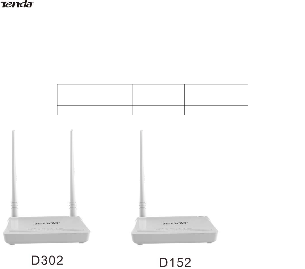
This user guide applies to the following four models: D302 and D152. The D302 is used as an example throughout
this user guide.
The differences between the two products are listed below:
Model Wireless Speed RJ45 Ports
D302 300M 2
D152 150M 2
What it does
The Wireless ADSL2+ Modem Router provides you with an easy and secure way to set up a wireless home network with
fast access to the Internet over a high-speed digital subscriber line (DSL). Complete with a built-in ADSL modem, it is
compatible with all major ADSL Internet service providers. It offers wireless speeds of up to 300 Mbps needed for
demanding applications, such as large file transfers, streaming HD video, and multiplayer gaming. The unit comes with a
wide range of premium features and applications such as IPv6, TR069, SNMP, Multicast, IP tunnel, IPTV service and
parental controls, etc. Plus, with the router, you can access Internet via the ATM interface or Ethernet interface.
Product Features
¾Wireless N speeds up to 300 Mbps for streaming HD videos and online gaming in addition to basic Internet
applications.
¾All-in-one device combines a Built-in ADSL2+ modem, wired router, wireless router and switch
¾Advanced QoS helps prioritize media streaming and gaming applications for best entertainment experience
¾Parental Control keeps your kids Internet experience safe using flexible and customizable filter settings
¾One-touch WPS ensures a quick and secure network connection
¾WEP and WPA/WPA2 are supported for advanced encryptions
¾Compatibility: Works with all major ADSL Internet service providers (ISPs); Backward compatible with 802.11b/g
WiFi devices

Wireless Modem Router User Guide
-7 -
¾Interchangeable LAN/WAN ports to schedule the Ethernet port to function either as a LAN or a WAN port
¾Interchangeable LAN/IPTV to schedule the Ethernet port to function either as a LAN or an IPTV port
¾Optional Ethernet and ADSL Uplinks: Access Internet via ADSL2+ Broadband Internet Service or an
interchangeable LAN/WAN RJ-45 port
¾Multiple Internet Connection Types: Bridging, PPPoE, IPoE, PPPoA, IPoA, dynamic IP and static IP
¾IPTV Service lets your surf Internet while watching online TV
¾6000V lightning
ˉ
proof design fits into lightning-intensive environment
¾Strong driving capability up to 6.5Km transmission distance
¾High speed ADSL speed up to 24Mbps downstream 1Mbps upstream
¾Built-in firewall prevents hacker attacks
¾Channel auto-select for optimum performance
¾FDM technology enables telephoning, faxing and surfing activities to proceed simultaneously without mutual
interference
¾Other Advanced Features: IPv6, DDNS, virtual server, DMZ, port triggering, IP filter, MAC filter and UPnP, etc
¾Tenda Setup Wizard for easy and fast installation and configuration
¾Tenda Green: Use hardware Power On/Off and software WiFi On/Off buttons to turn on and off power and WiFi to
save energy when not in use
Package Contents
Your box should contain the following items:
¾Wireless Modem Router
¾Phone cable
¾Ethernet cable
¾ADSL2+ filter
¾Quick install guide
¾Power adapter
¾Resource CD
If any of the parts are incorrect, missing, or damaged, keep the carton, including the original packing materials and
contact your Tenda dealer for immediate replacement.
Wireless Modem Router User Guide
-8 -
Chapter 2 Hardware Install
If you have not already set up your new router using the Quick Install Guide that comes in the box, this chapter walks
you through the hardware install. To set up your Internet connection, see Chapter 2 Quick Internet Setup.
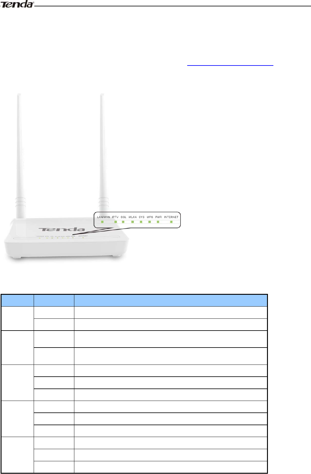
Front Panel
The LEDs on the device are described below:
LED Status Description
Power
Solid Power is supplied to the device.
Off Power is not supplied to the device.
SYS
Blinking System is functioning correctly.
Solid/Off System is functioning incorrectly.
WLAN
Blinking Transferring data
Off Wireless is disabled.
Solid Wireless is enabled.
ADSL
Slow Blink Physical connection failure.
Fast Blink Synchronizing...
Solid ADSL connection is established.
LAN
Off No connection established.
Blinking Transferring data
Solid Connection is established.
Wireless Modem Router User Guide
-9 -
WPS
Solid Client connected successfully.
Blinking The WPS LED starts blinking if you pressed the WPS button on the
device or interface.
Off If there is no wireless clients connected, the WPS LED turns off after
blinking for 2 minutes.
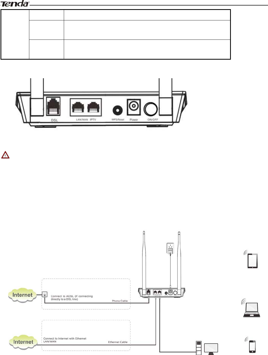
Back Panel
¾ON/OFF: Power switch to turn the router on or off.
_________________________________________________________________________________________________
Note:
Please use the included power adapter. Use of a power adapter with different voltage rating may damage the device.
_________________________________________________________________________________________________
¾WPS/RESET: Press it for 1-3 seconds to enable WPS connection or 7 seconds to restore all configurations to
factory defaults.
¾LAN: Ethernet RJ-45 LAN ports to cable the device to the local network devices such as computers.LAN:
Ethernet RJ-45 LAN ports to cable the device to the local network devices such as computers.
¾DSL: RJ-11 Asynchronous DSL (ADSL) port for connecting the device to a DSL line.
Follow the diagram below to install the device.

Wireless Modem Router User Guide
- 10 -
Chapter 3 Quick Internet Setup
This chapter instructs you to quickly set up your Internet connection.
The Quick Internet Setup applies only to ADSL Uplink mode. If you are not directly connecting to the ADSL line via a
phone cable, please click the Advanced button on the home page and then select Advanced Setup -> Layer2 Interface
-> ETH Interface. For more information, see To set up the ETH interface and To setup WAN Service for ETH
Interface.
3.1 Log in to Web Manager
You can log in to the modem router’s web manager with the Setup Wizard on the included CD automatically or using a
web browser manually. The Setup Wizard on the auto-run CD can automatically configure your PC’s TCP/IP properties
and direct you to the web login window without requiring the IP address.
Using Setup Wizard
1. Insert the included resource CD into your computer’s drive and the CD automatically runs. If the CD does not run
automatically, double click . You will see the screen below.
2. Click Run and it will automatically configure your PC’s TCP/IP properties. If your PC is successfully configured, the
login window below will display.

Wireless Modem Router User Guide
-11 -
Using Browser
1. Set your PC to Obtain an IP address automatically. For more information, see Appendix 1 Configure Your PC.
2. Launch a web browser and enter 192.168.1.1 to display the login window.
3. Enter admin in both the login User Name and Password boxes if you first time access the router and then click the
Login button to enter the screen below.
_________________________________________________________________________________________________
Tip:
If you changed the login user name and password and forget them, press the Reset button on the device and then enter
the default settings of admin.
_________________________________________________________________________________________________
Wireless Modem Router User Guide
- 12 -
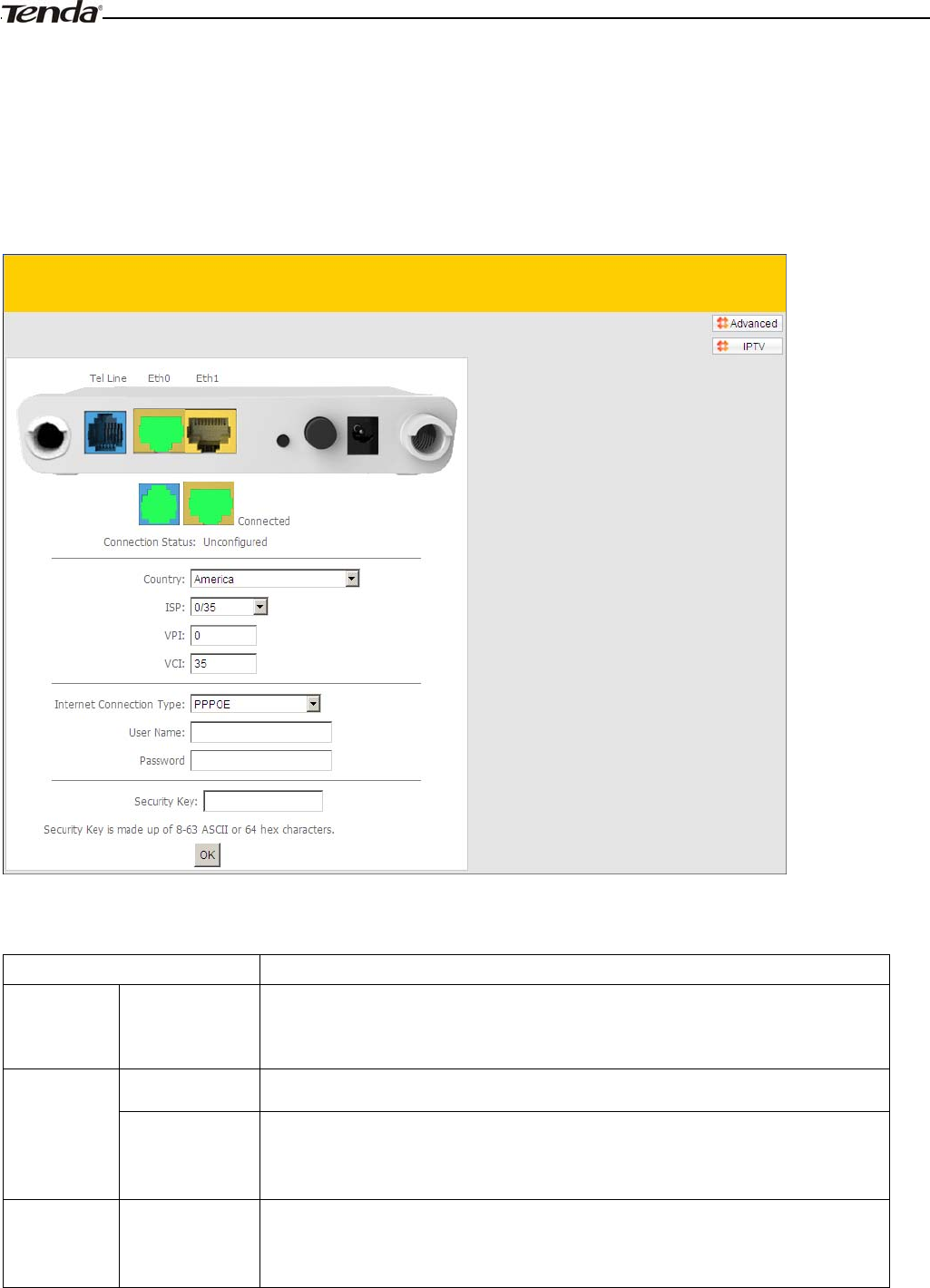
3.2 Internet Setup
a. Select your country.
b. Select your ISP.
c. VPI and VCI fields will be populated automatically if you select a correct country and ISP.
d. Select your Internet connection type.
Depending on the type of connection, you are prompted to enter your ISP settings, as shown in the following table:
Internet Connection Type ISP Information
PPPoE
PPPoA
Enter the ISP login user name and password. If you cannot locate this
information, ask your ISP to provide it.
IPoE Dynamic IP No entries are needed.
Static (Fixed)
IP
Enter the assigned IP address, subnet mask, and the IP address of your ISP’s
primary DNS server. This information should have been provided to you by
your ISP. If a secondary DNS server address is available, enter it also.
IPoA Static (Fixed)
IP
Enter the assigned IP address, subnet mask, and the IP address of your ISP’s
primary DNS server. This information should have been provided to you by
your ISP. If a secondary DNS server address is available, enter it also.

Wireless Modem Router User Guide
- 13 -
_________________________________________________________________________________________________
Note:
If your country and/or your ISP are not covered on the home page, please click the button on the
home page and then select Advanced Setup -> Layer2 Interface -> ATM Interface and then click Add there to manually
configure the VPI and VCI. If you cannot locate this information, refer to Appendix 4 VPI/VCI List or ask your ISP to
provide it. For more information, see To set up the ATM interface and To setup WAN Service for ATM Interface.
_________________________________________________________________________________________________
e. After you configure all the above settings, click OK to save and apply them.
f. Test Internet Connectivity
Launch a web browser and enter www.tendacn.com. If the webpage is opened, you are connected to Internet.
3.3 Quick Wireless Security Setup
For security purpose, we strongly recommend you to customize a new security key. Simply enter 8-63 ASCII or 64 hex
characters.
_________________________________________________________________________________________________
Tip:
1. If you customize a new security key, write it on a sticky label and attach it to the bottom of the unit. You will need the
new security key if you wish to connect to the device wirelessly in the future.
2. To join your secured wireless network, see Appendix 2 Join Your Wireless Network.
_________________________________________________________________________________________________
Wireless Modem Router User Guide
- 14 -
Chapter 4 Advanced Settings
This chapter describes the advanced features of your router.
The information is for users with a solid understanding of networking concepts who want to configure the router for
unique situations.
This chapter includes the following sections:
•Device Info
•Advanced Setup
•Wireless
•Diagnostics
•Management
Click Advanced on the home page to enter the screen below.
Wireless Modem Router User Guide
- 15 -
4.1 Device Info
This section includes the following information:
• Summary
•WAN
•Statistics
• Route
•ARP
•DHCP
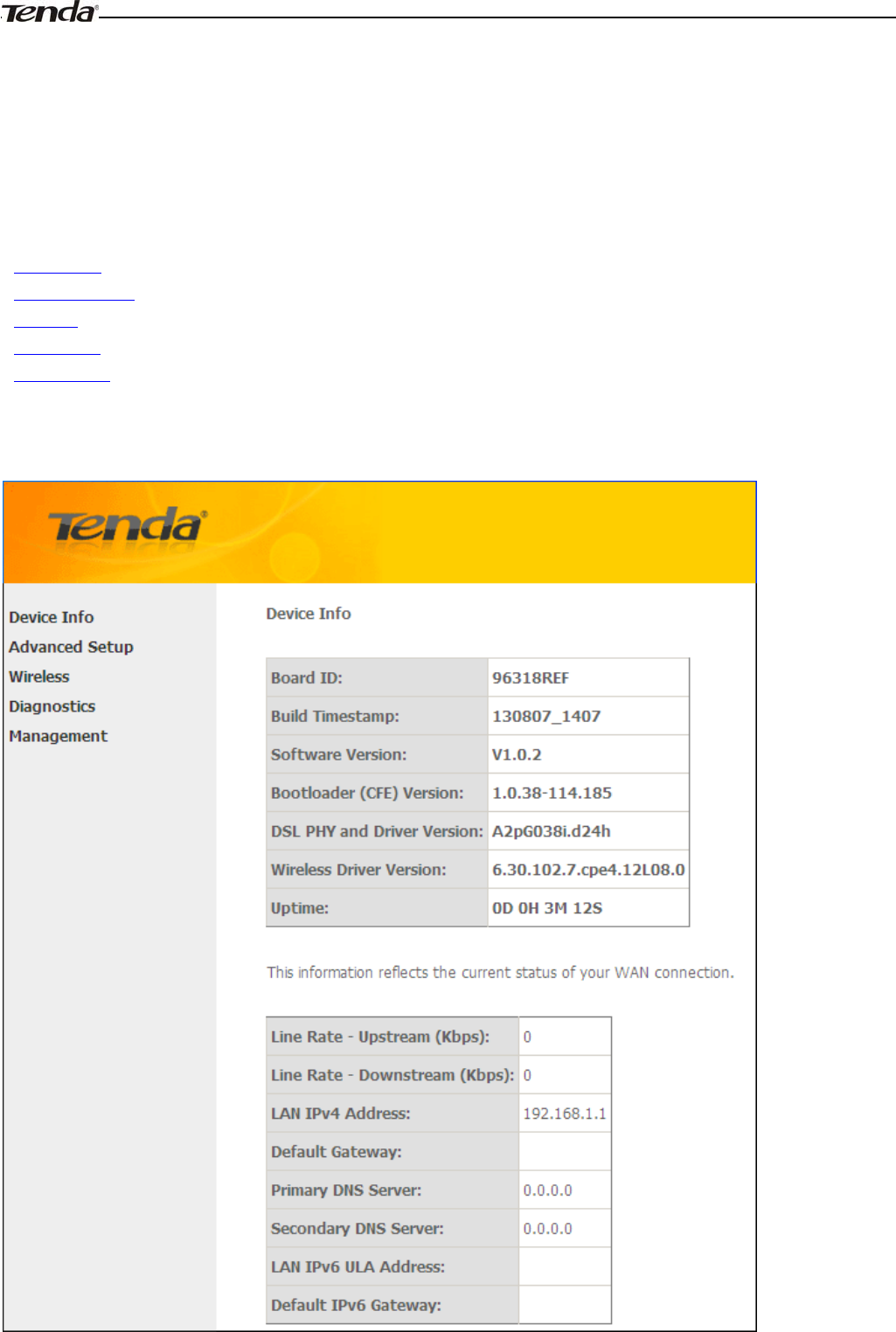
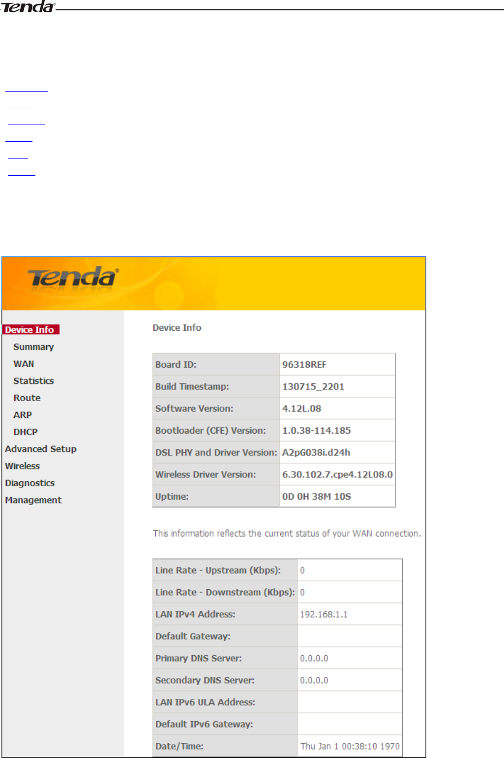
Summary
Here you can view system information and current status of your WAN connection as seen in the screenshot.
Wireless Modem Router User Guide
- 16 -
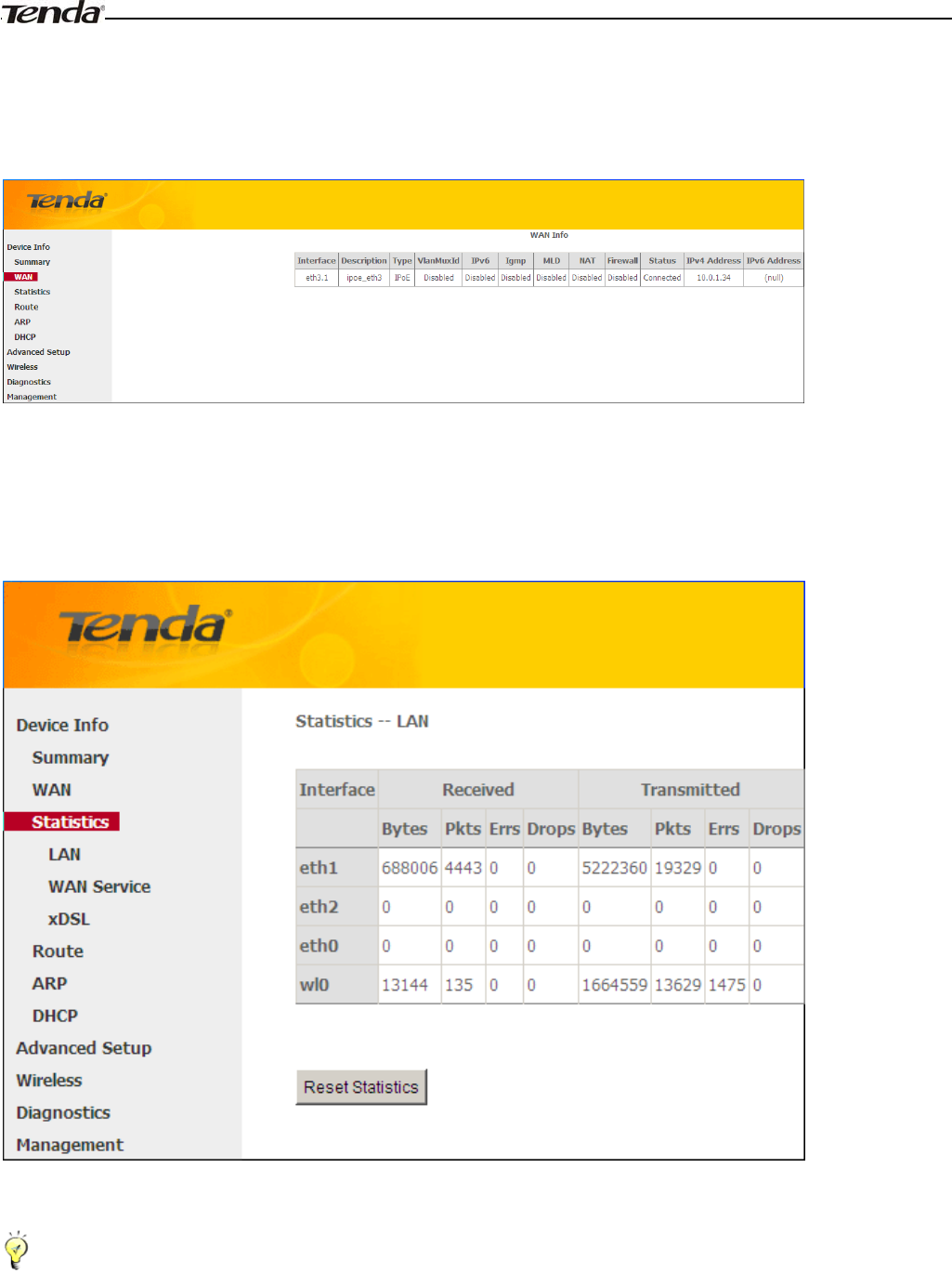
WAN
Here you can view the WAN Information including Interface, Description, Type, IGMP, NAT, Firewall, Status, IPv4
Address and VLAN ID as seen in the screenshot.
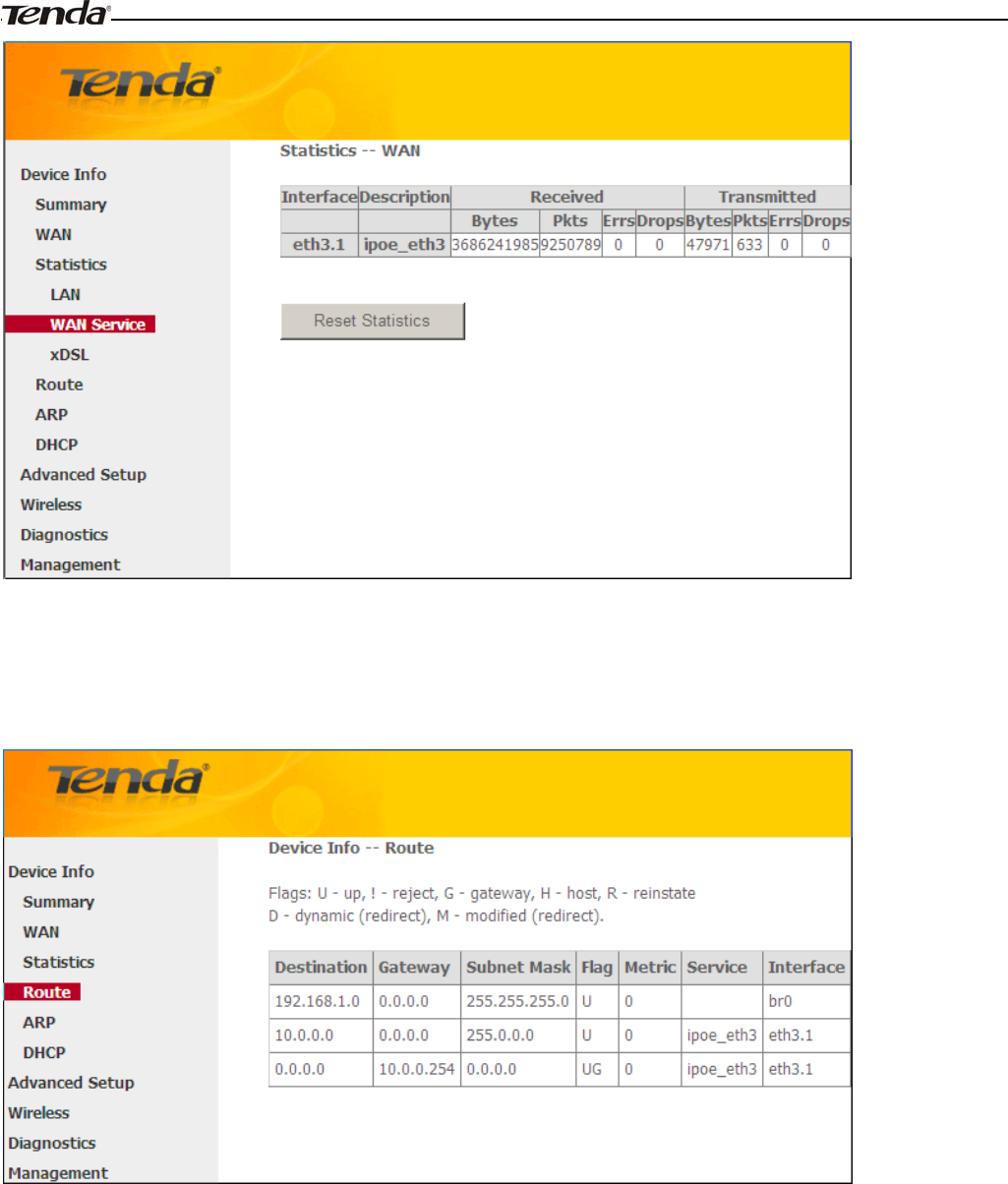
Statistics
Here you can view the packets received and transmitted on LAN/WAN ports.
Statistics--LAN: Displays the packets received and transmitted on the LAN ports as seen in the screenshot below.
_________________________________________________________________________________________________
Tip:
eth0, eth1, eth3 and eth3 respectively represent the LAN port1, LAN port2, LAN port3 and LAN port4 of the device.
_________________________________________________________________________________________________
Statistics--WAN: Displays the packets received and transmitted on the WAN ports as seen in the screenshot below.
Wireless Modem Router User Guide
- 17 -
Route
Here you can view the route table as seen in the screenshot:
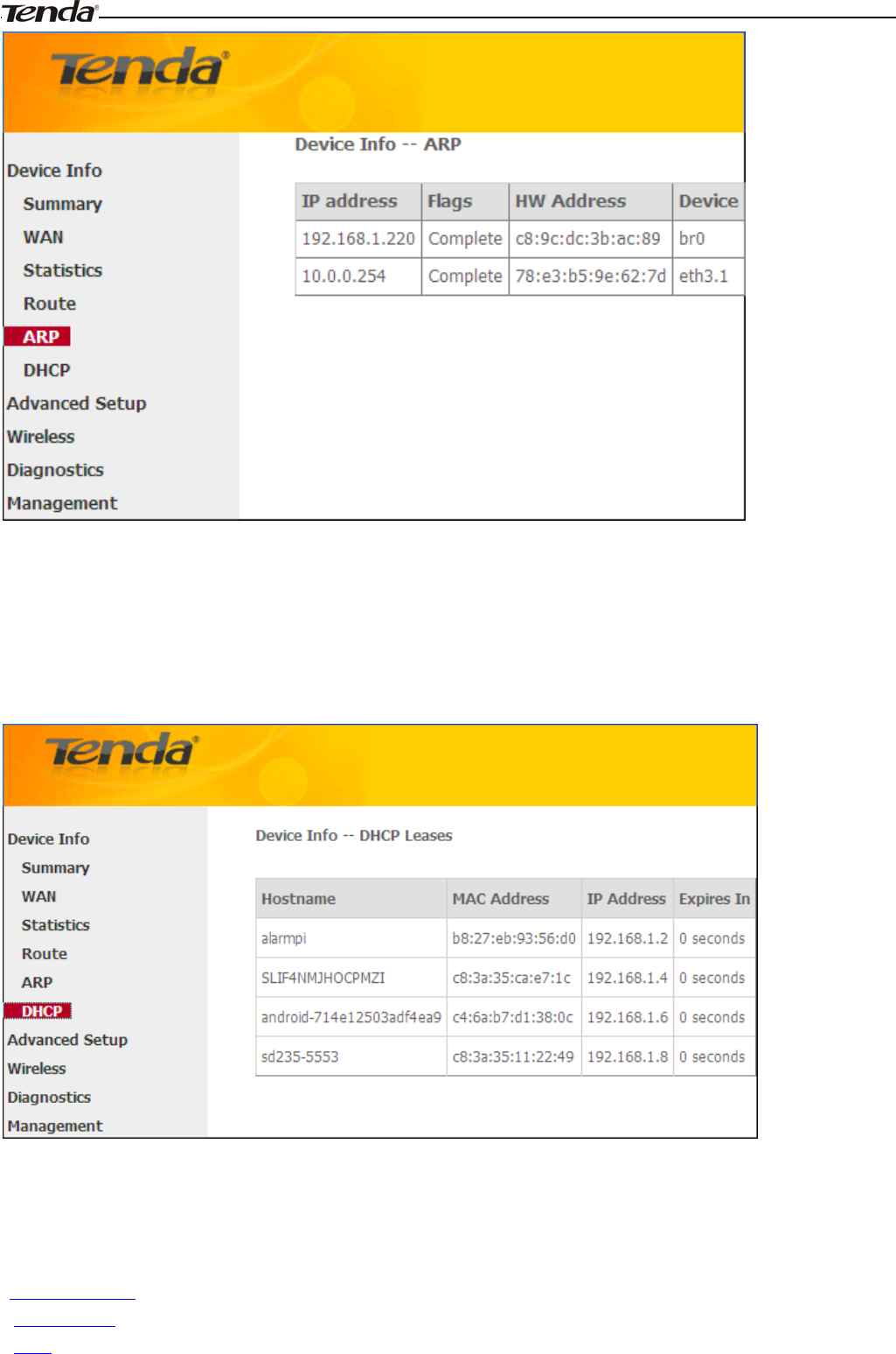
ARP
Here you can view the IP and MAC addresses of the PCs that attach to the device either via a wired or wireless
connection as seen in the screenshot:
Wireless Modem Router User Guide
- 18 -
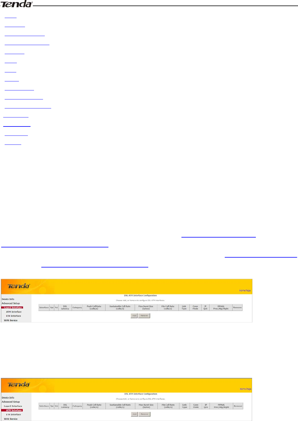
DHCP
Here you can view the DHCP leases, including IP and MAC addresses of the PCs, hostnames and remaining lease time
as seen in the screenshot:
4.2 Advanced Setup
This section explains the following information:
• Layer2 Interface
•WAN Service
•LAN
Wireless Modem Router User Guide
- 19 -
•NAT
•Security
•Parental Control
•Quality of Service
•Routing
•DNS
•DSL
•UPnP
•Print Server
•Storage Service
•Interface Grouping
• IP Tunnel
• Certificate
•Multicast
•IPTV
4.2.1 Layer2 Interface
Click Advanced Setup -> Layer2 Interface to enter the Layer2 Interface screen.
This router provides two Layer2 Interfaces:
- ATM Interface for ADSL broadband Internet service
- ETH Interface for connecting to Internet via an Ethernet cable.
By default, system applies the ATM Interface (ADSL uplink).
If you directly connect to the ADSL line via a phone cable, first refer to To set up the ATM interface and then skip to
To setup WAN Service for ATM Interface.
Or if you connect to Internet via a fiber/cable modem using an Ethernet cable, first refer to To set up the ETH interface
and then skip to To setup WAN Service for ETH Interface.
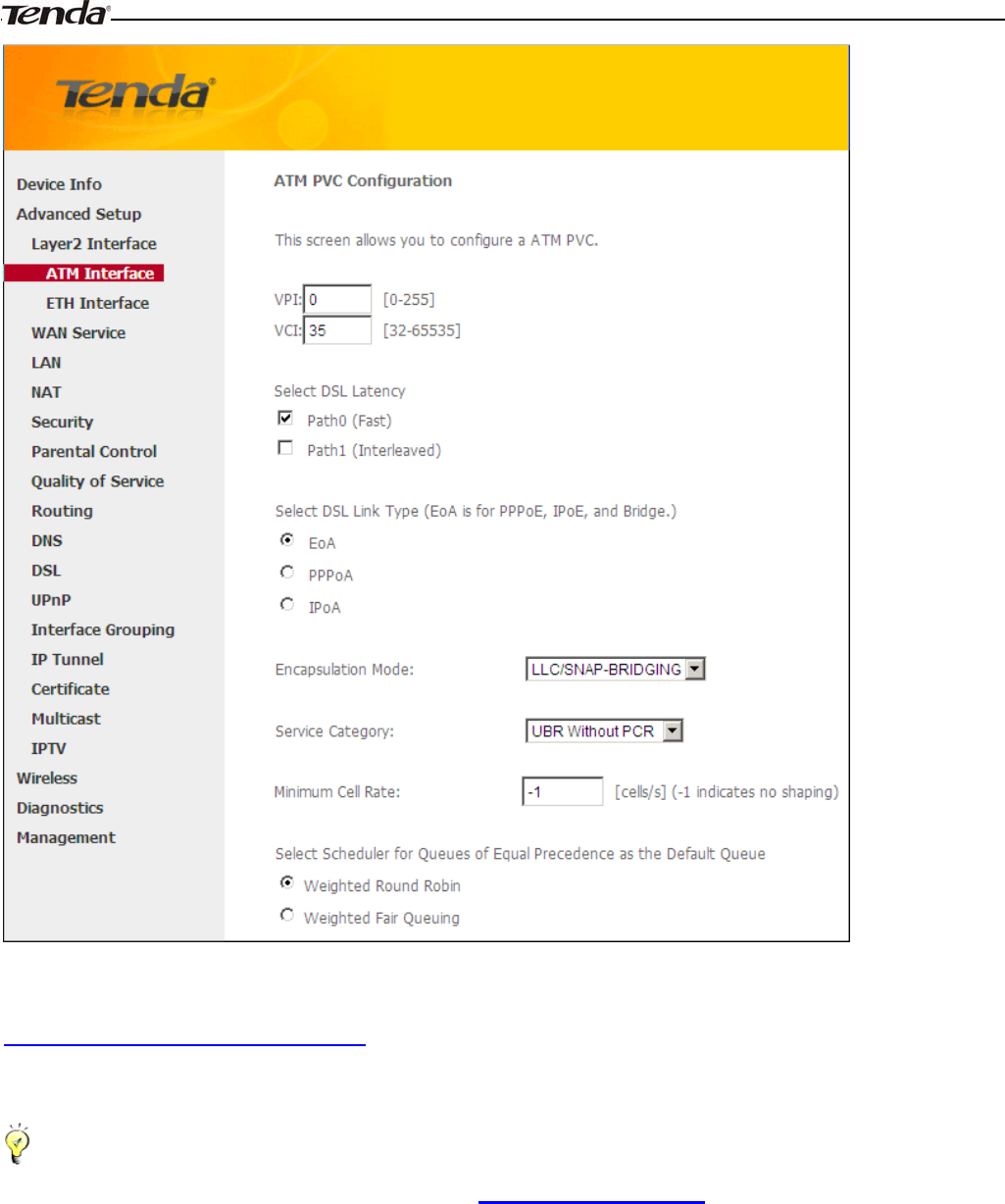
To set up the ATM interface
Select ATM Interface and click Add to configure it.
Wireless Modem Router User Guide
- 20 -
Enter the VPI and VCI values, Select a DSL Link Type (Internet connection type): EoA (EoA is for PPPoE, IPoE, and
Bridge.), PPPoA or IPoA, leave other options unchanged from factory defaults and click Apply/Save and then refer to
To setup WAN Service for ATM Interface to configure the WAN service for Internet access.
_________________________________________________________________________________________________
Tip:
If you are unsure about the VPI/VCI parameters, see Appendix 4 VPI/VCI List. Or if your ISP and the VPI/VCI
information is not covered there, ask your ISP to provide it.
_________________________________________________________________________________________________
To set up the ETH interface
Select ETH Interface and click Add to configure it.
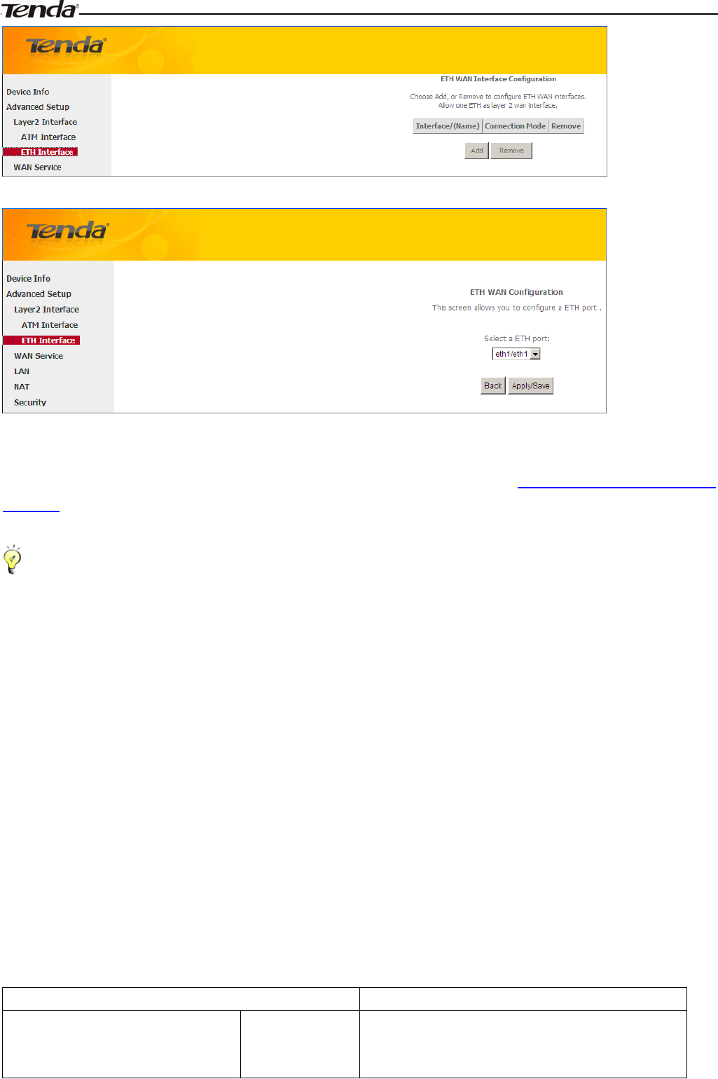
Wireless Modem Router User Guide
- 21 -
The Ethernet port configured here is to function as a WAN port. Only one LAN port can be configured as the WAN port
at a time. After you finish your settings, click the Apply/Save button and then refer to To setup WAN Service for ETH
Interface to configure the WAN service for Internet access.
_________________________________________________________________________________________________
Tip:
eth0, eth1, eth3 and eth3 respectively represent the LAN port1, LAN port2, LAN port3 and LAN port4 of the device.
_________________________________________________________________________________________________
4.2.2 WAN Service
This router provides two WAN services:
-WAN Service for ATM Interface (ADSL uplink)
- WAN Service for ETH Interface (Ethernet uplink)
To setup WAN Service for ATM Interface
If you configured the ATM Interface (ADSL uplink), follow steps below to configure the WAN service:
Click Advanced Setup -> WAN Service and then click the Add button. Select the interface you have configured
Depending on the type of connection, you will come to different screens and be prompted to enter your ISP settings
accordingly. Select one connection type from the five Internet connection types as shown in the following table (If you
are unsure, consult your ISP.):
Internet Connection Type ISP Information
PPPoE
PPPoA
Enter the ISP login user name and password. If you
cannot locate this information, ask your ISP to
provide it.
Wireless Modem Router User Guide
- 22 -
IPoE
(If your ISP uses DHCP to assign
your IP address or if your ISP assigns
you a static (fixed) IP address, IP
subnet mask and the gateway IP
address, you need to select the IP
over Ethernet (IPoE).
Dynamic IP No entries are needed.
Static (Fixed) IP Enter the assigned IP address, subnet mask, and the
IP address of your ISP’s primary DNS server. This
information should have been provided to you by
your ISP. If a secondary DNS server address is
available, enter it also.
IPoA Static (Fixed) IP Enter the assigned IP address, subnet mask, and the
IP address of your ISP’s primary DNS server. This
information should have been provided to you by
your ISP. If a secondary DNS server address is
available, enter it also.
Bridging If you wish to iniate a dialup directly from your PC
for Internet access or enjoy the entire Internet
connection (instead of sharing it with others), you
can select the Bridging and then click Next.
_________________________________________________________________________________________________
Tip:
For PPPoE, IPoE, and Bridging Internet connection types, you must first select EoA on the ATM Interface Screen, for
more information, see To set up the ATM interface.
_________________________________________________________________________________________________
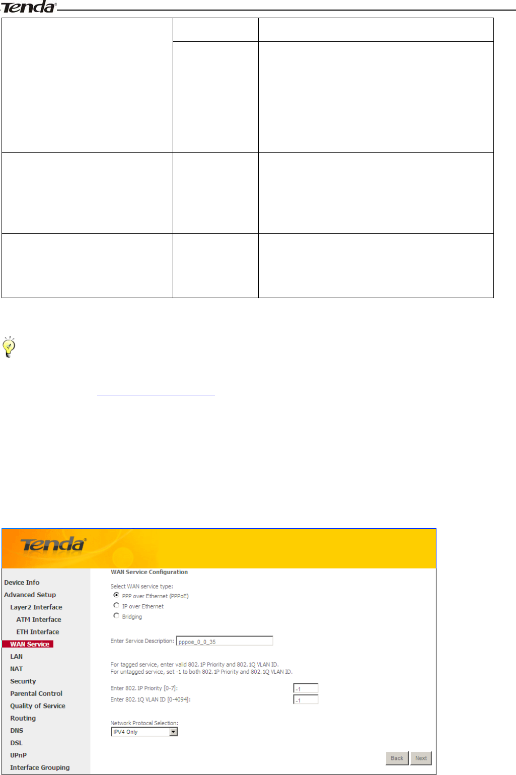
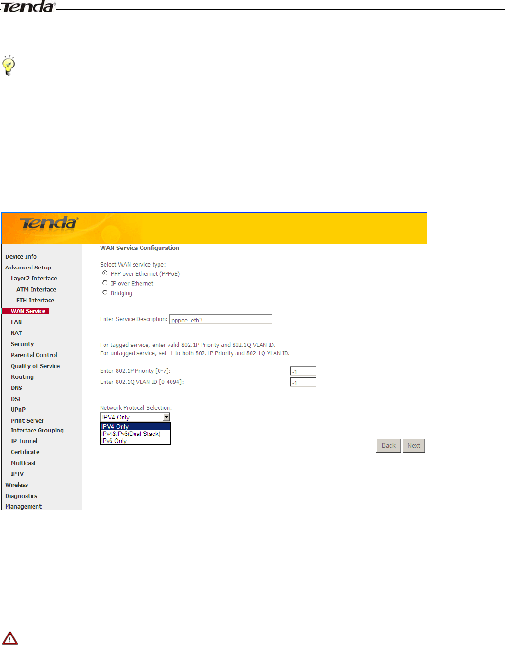
PPP over Ethernet (PPPoE)
If you have selected the EoA from the ATM Interface screen in Layer2 Interface, you will see the screen below when
you click the WAN Service tab, select the configured interface and click Next.
Wireless Modem Router User Guide
-23-
1. Select PPPoE.
2. Edit the Enter Service Description. This field is optional. We recommend that you keep the default.
3. Select a network protocol: IPv4, IPv6 or IPv4 & IPv6 (dual stack).
4. Click Next.
_________________________________________________________________________________________________
Note:
If you select IPv6 or IPv4 & IPv6 (dual stack), skip to IPv6.
_________________________________________________________________________________________________
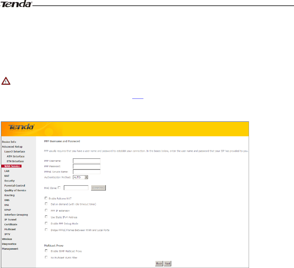
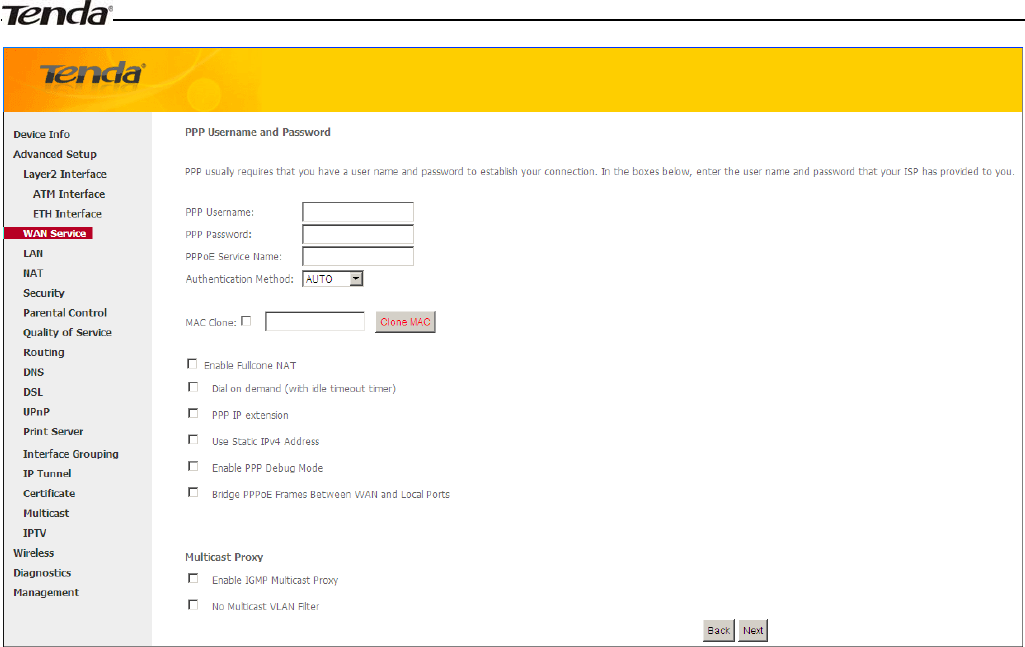
¾PPP User Name: This is for logging in to your ISP. If you cannot locate this information, ask your ISP to provide
it.
¾PPP Password: This is for logging in to your ISP. If you cannot locate this information, ask your ISP to provide it.
¾PPPoE Service Name: This information is provided by your ISP. Only enter it if instructed by your ISP.
¾Authentication Method: This is used by ISP to authenticate the client that attempts to connect. If you are not sure,
consult your ISP or select Auto.
¾Clone MAC: Clicking this button copies the MAC address of your PC to the router. Many broadband ISPs restrict
access by allowing traffic only from the MAC address of your broadband modem, but some ISPs additionally
register the MAC address of the network interface card in your computer when your account is first opened. They
then accept traffic only from the MAC address of that computer. If so, configure your router to “clone” the MAC
address from the authorized computer.
¾Dial on demand: Connect to ISP only when there is traffic transmission. This saves your broadband Internet
service bill.
¾PPP IP extension: If enabled, all the IP addresses in outgoing packets including management packets on the WAN
port will be changed to the device's WAN IP address. Only change the default settings if necessary.
¾Enable PPP Debug Mode: Only enable this feature if supported by your ISP.
¾Bridge PPPoE Frames Between WAN and Local Ports: If enabled, PPPoE dialup frame from LAN side will
directly egress the WAN port without modification.
Wireless Modem Router User Guide
- 24 -
¾Multicast Proxy: If enabled, the router will use multicast proxy.
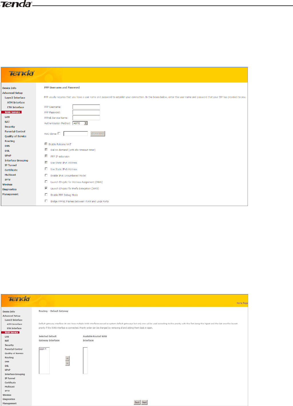
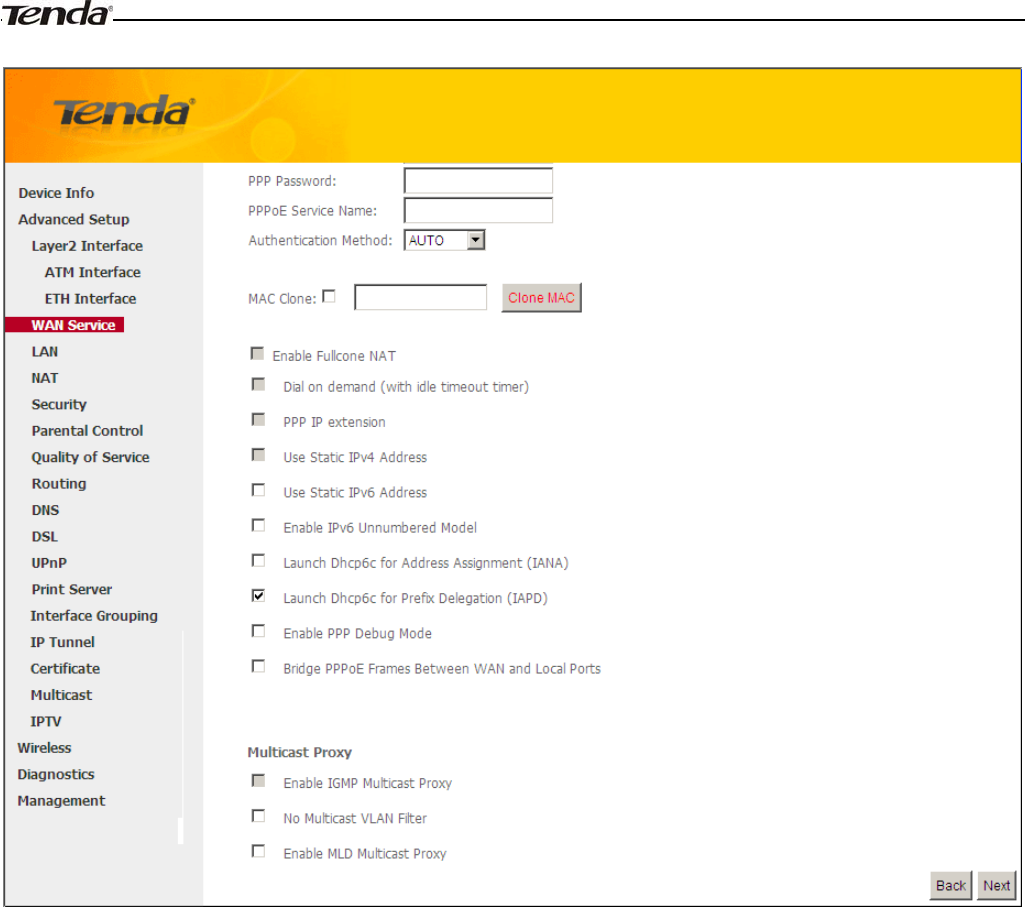
IPv6
If you select IPv4 as the network protocol, skip this section.
1. Check Launch Dhcp6c for Prefix Delegation (IAPD).
2. If your ISP is using stateful DHCPv6, check Launch Dhcp6c for Address Assignment (IANA) also. Or configure
a static IP address.
3. Click Next -> Next -> Apply/Save.
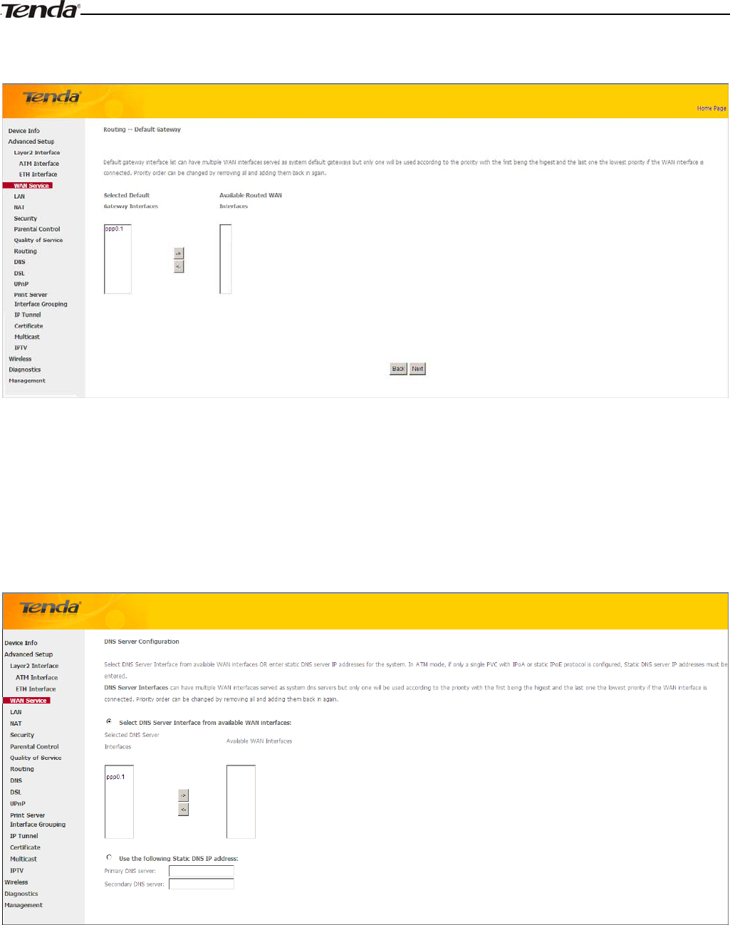
WAN G a t ew ay
Here you can configure the WAN gateway address. After you configure it click Next. The default setting is
recommended.
Wireless Modem Router User Guide
- 25 -
_________________________________________________________________________________________________
Note:
Default gateway interface list can have multiple WAN interfaces served as system default gateways but only one will be
used according to the priority with the first being the higest and the last one the lowest priority if the WAN interface is
connected. Priority order can be changed by removing all and adding them back in again.
_________________________________________________________________________________________________
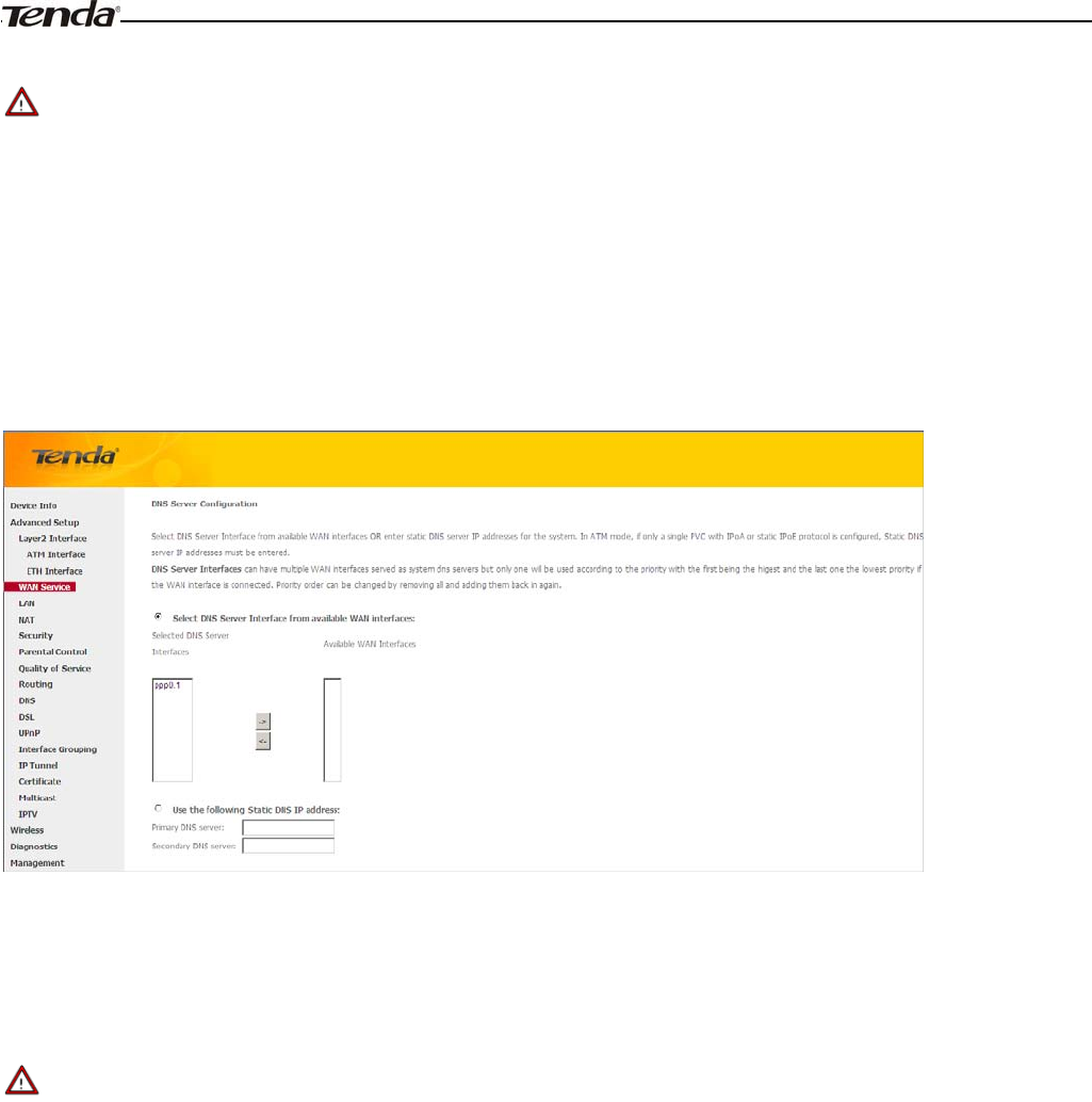
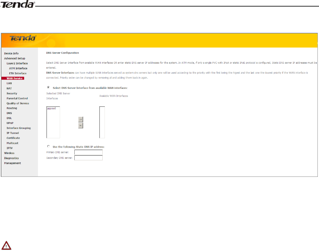
WAN DNS
Here you can configure the WAN DNS address:
-Click the Select DNS Server Interface from available WAN interfaces option
-OR select the Use the following Static DNS IP address option and enter static DNS server IP addresses for the system
And then click Next.
_________________________________________________________________________________________________
Note:
1. DNS Server Interfaces can have multiple WAN interfaces served as system dns servers but only one will be used
according to the priority with the first being the higest and the last one the lowest priority if the WAN interface is
connected. Priority order can be changed by removing all and adding them back in again.
2. In ATM mode, if only a single PVC with IPoA or static IPoE protocol is configured, Static DNS server IP addresses
must be entered.
3. If you cannot locate the static DNS server IP information, ask your ISP to provide it.
_________________________________________________________________________________________________
Wireless Modem Router User Guide
- 26 -
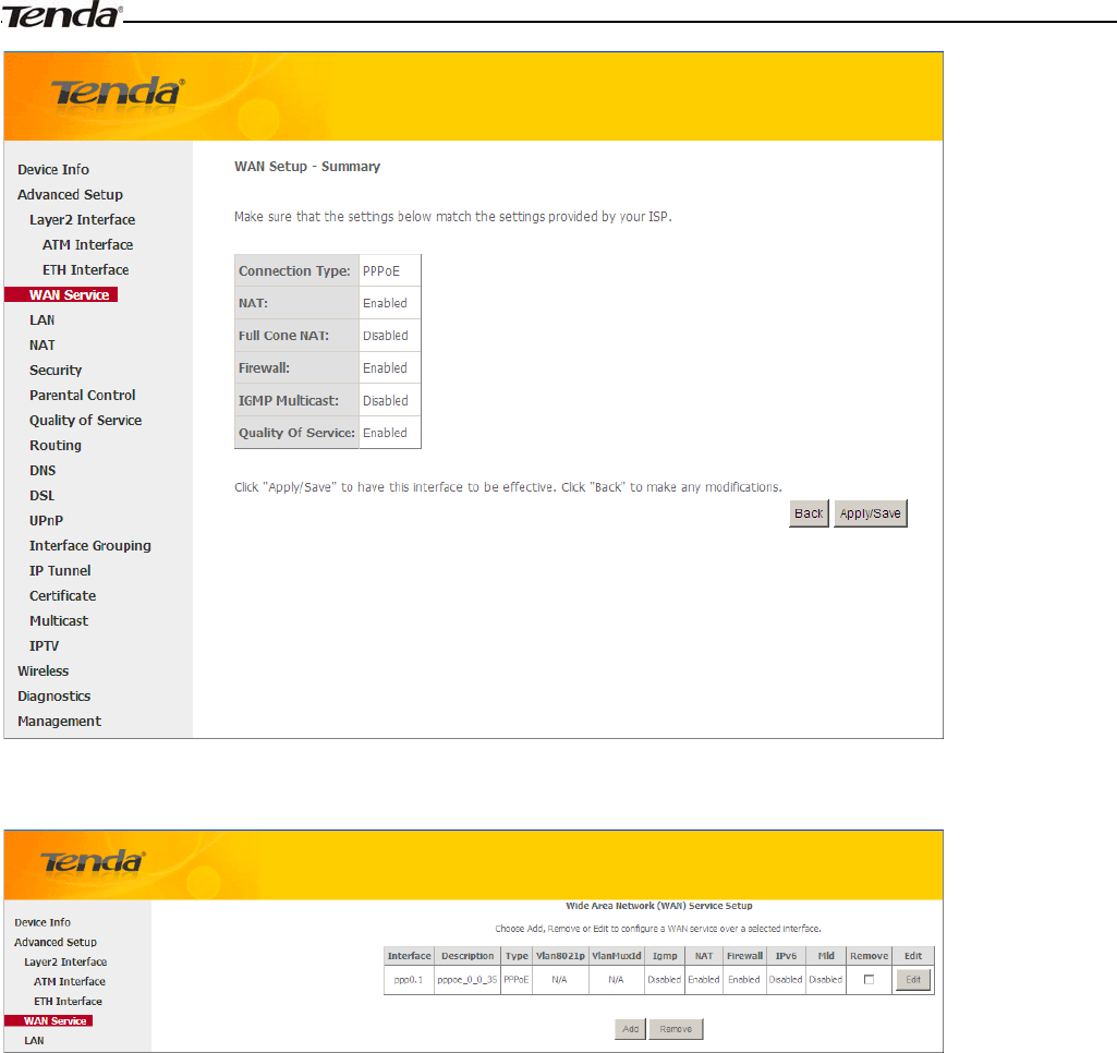
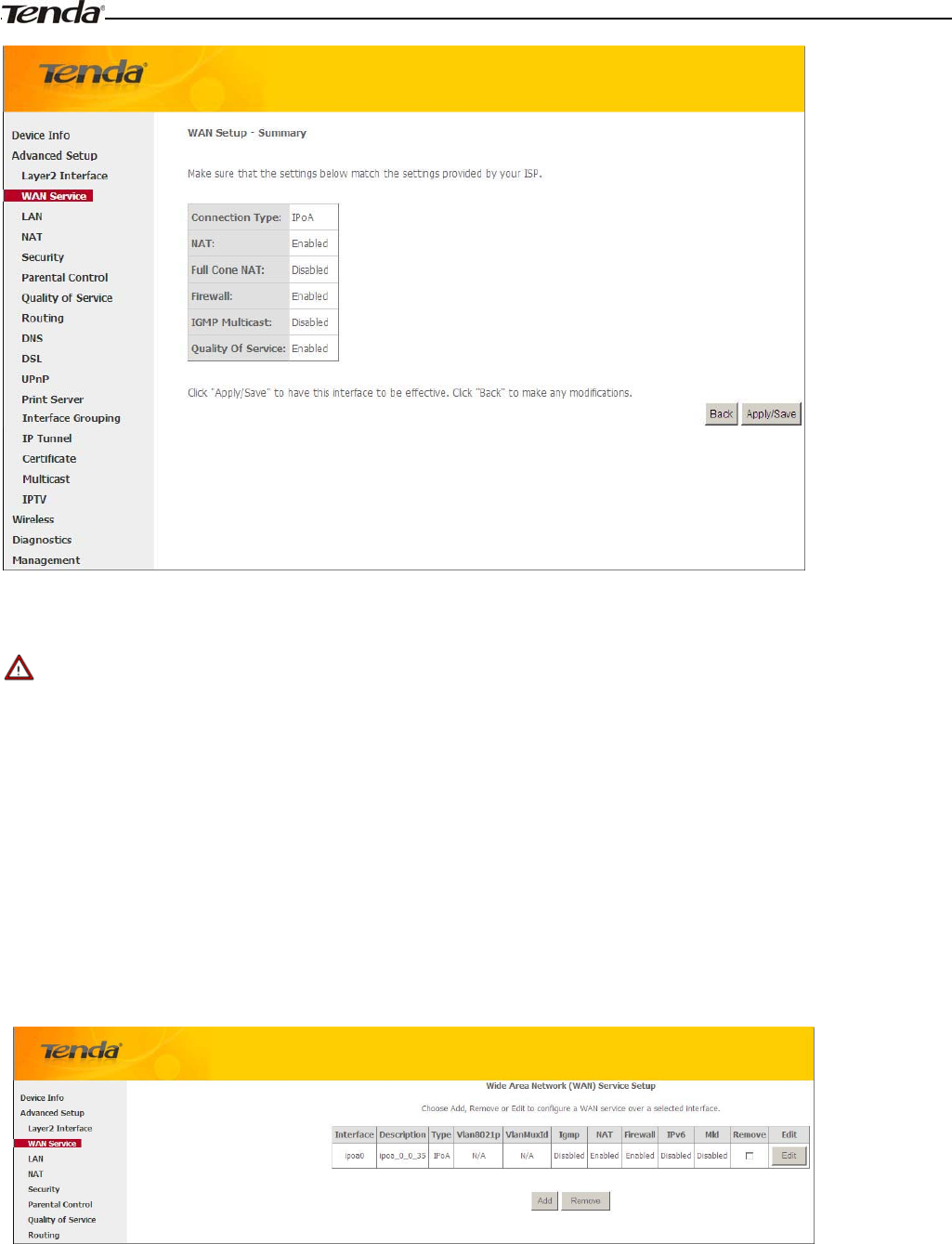
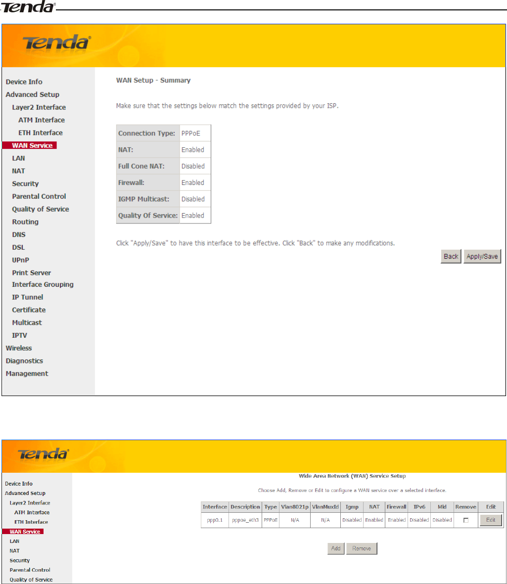
Here you can view your configurations. Click Apply/Save to save your settings if everything is correctly set.
When the PPPoE connection is successful, you can access Internet.
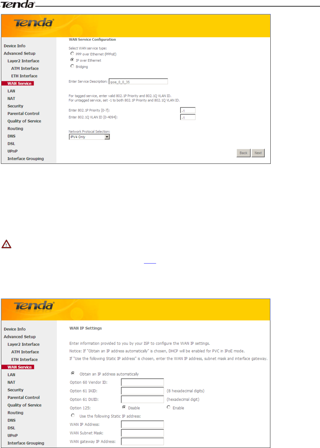
IP over Ethernet (IPoE)
If your ISP uses DHCP to assign your IP address or if your ISP assigns you a static (fixed) IP address, IP subnet mask
and the gateway IP address, you need to select the IP over Ethernet (IPoE).
If you have selected the EoA from the ATM Interface screen in Layer2 Interface, you will see the screen below when
you click the WAN Service tab, select the configured interface and click Next.
Wireless Modem Router User Guide
- 27 -
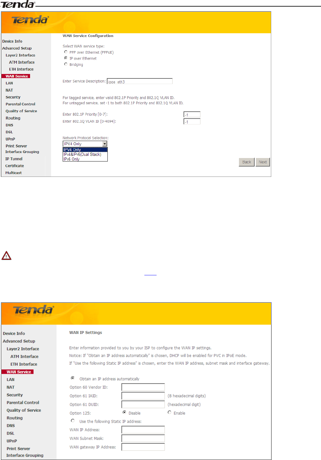
1. Select IPoE.
2. Edit the Enter Service Description. This field is optional. We recommend that you keep the default.
3. Select a network protocol: IPv4, IPv6 or IPv4 & IPv6 (dual stack).
4. Click Next.
_________________________________________________________________________________________________
Note:
If you select IPv6 or IPv4 & IPv6 (dual stack), skip to IPv6.
_________________________________________________________________________________________________
Wireless Modem Router User Guide
- 28 -
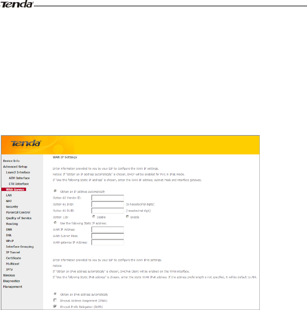
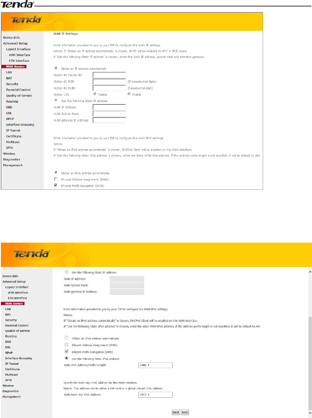
¾Obtain an IP address automatically: This allows the router to automatically acquire IP information from your ISP
or your existing networking equipment.
¾Use the following Static IP address: This allows you to specify the Static IP information provided by your ISP or
that corresponds with your existing networking equipment.
¾WAN IP Address: The Internet IP address provided by your ISP for accessing Internet.
¾WAN Subnet Mask: The subnet mask address provided by your ISP for accessing Internet.
¾WAN gateway IP Address: The gateway IP address provided by your ISP for accessing Internet.
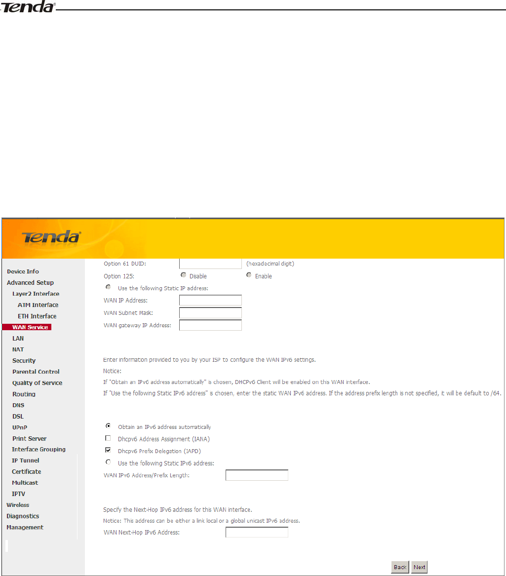
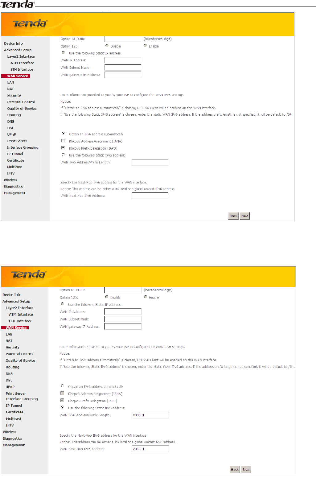
IPv6
If you select IPv4 as the network protocol, skip this section.
To obtain an IP address automatically:
1. Select Obtain an IP address automatically.
2. Check Launch Dhcp6c for Prefix Delegation (IAPD).
3. If your ISP is using stateful DHCPv6, check Launch Dhcp6c for Address Assignment (IANA) also.
4. Click Next -> Next -> Apply/Save.
Wireless Modem Router User Guide
- 29 -
To configure a static IPv6 address
1. Select Use the following Static IPv6 address.
2. Configure WAN IPv6 Address/Prefix Length and WAN Next-Hop IPv6 Address.
3. Click Next -> Next to enter the screen below.
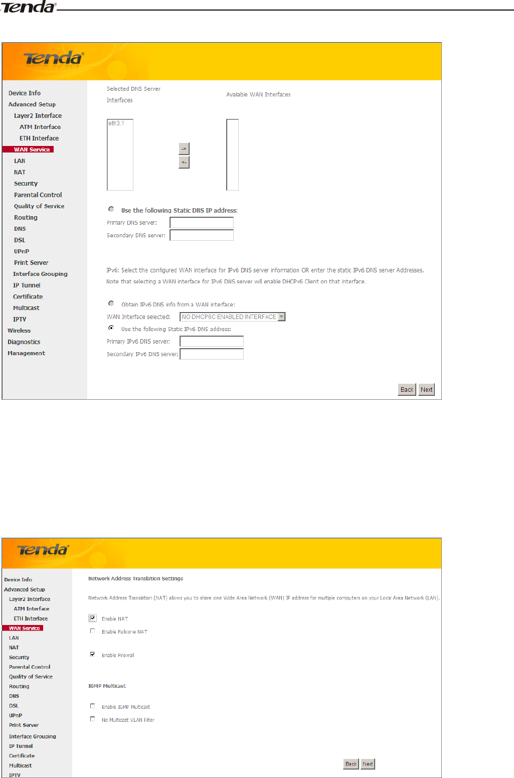
Wireless Modem Router User Guide
- 30 -
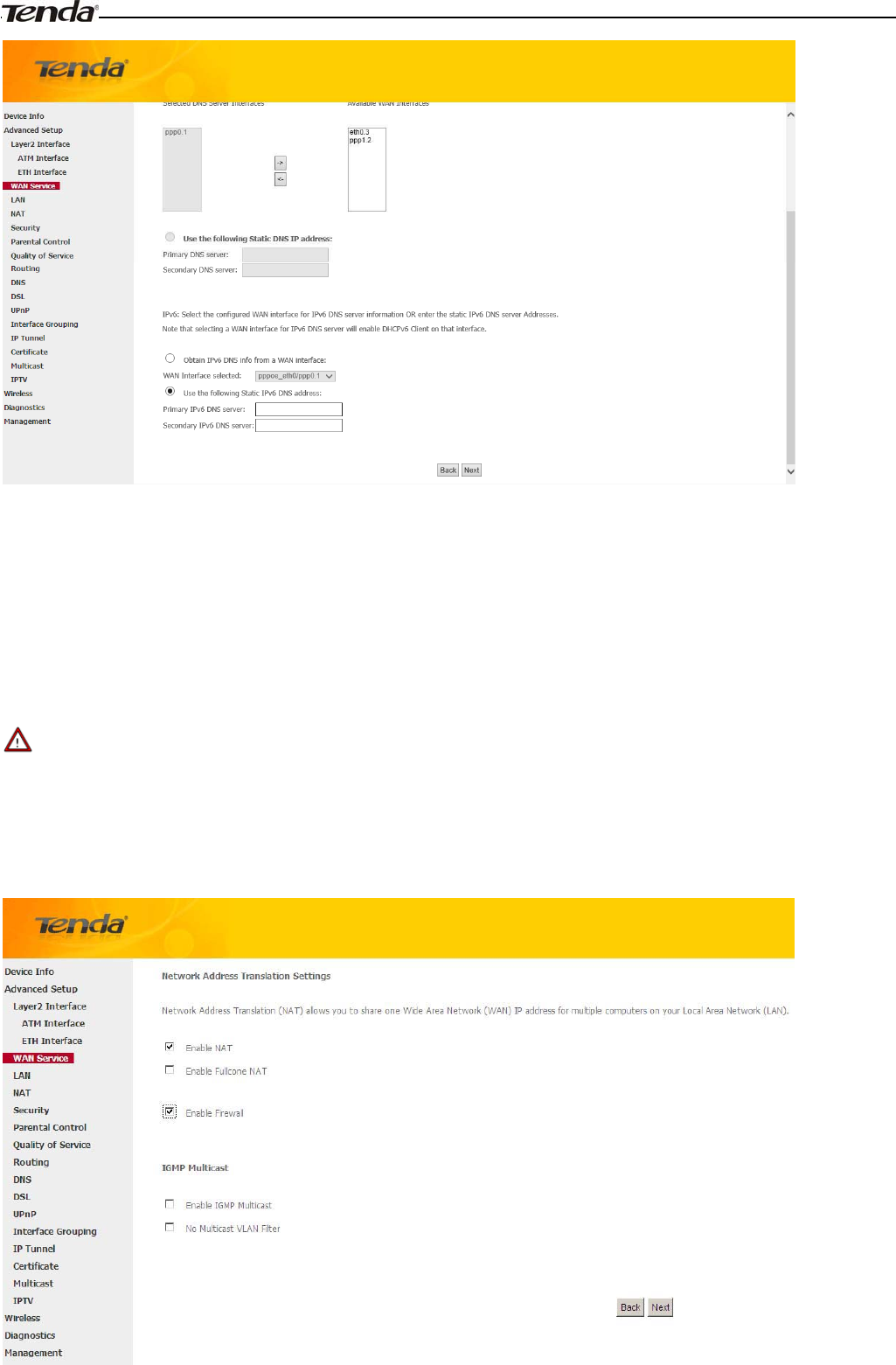
4. Select Use the following Static IPv6 DNS address and manually enter the DNS server address. If you have two
DNS server addresses, enter the second also.
5. Click Next -> Apply/Save.
_________________________________________________________________________________________________
Note:
If "Obtain an IP address automatically" is chosen, DHCP will be enabled for PVC in IPoE mode.
_________________________________________________________________________________________________
Wireless Modem Router User Guide
- 31 -
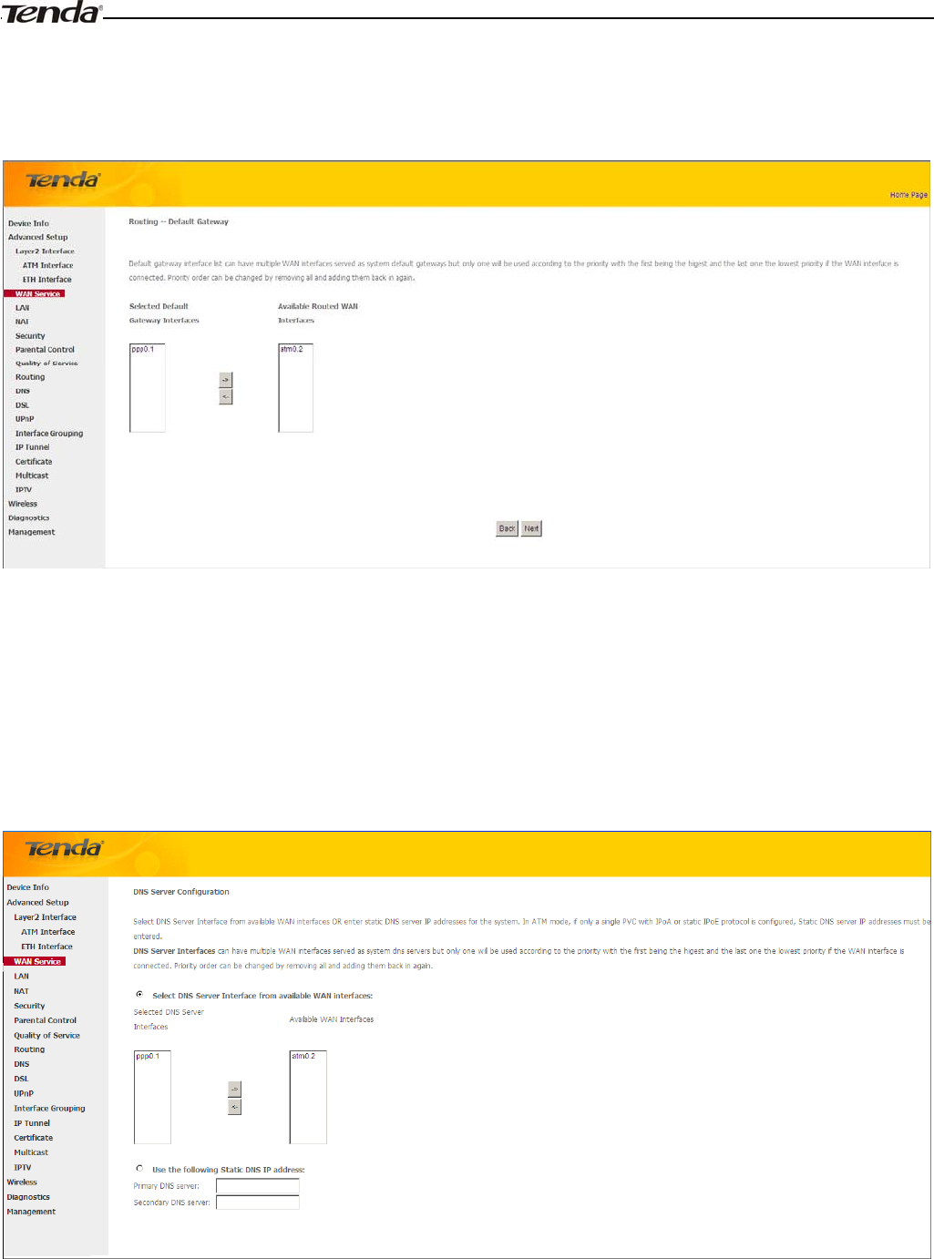
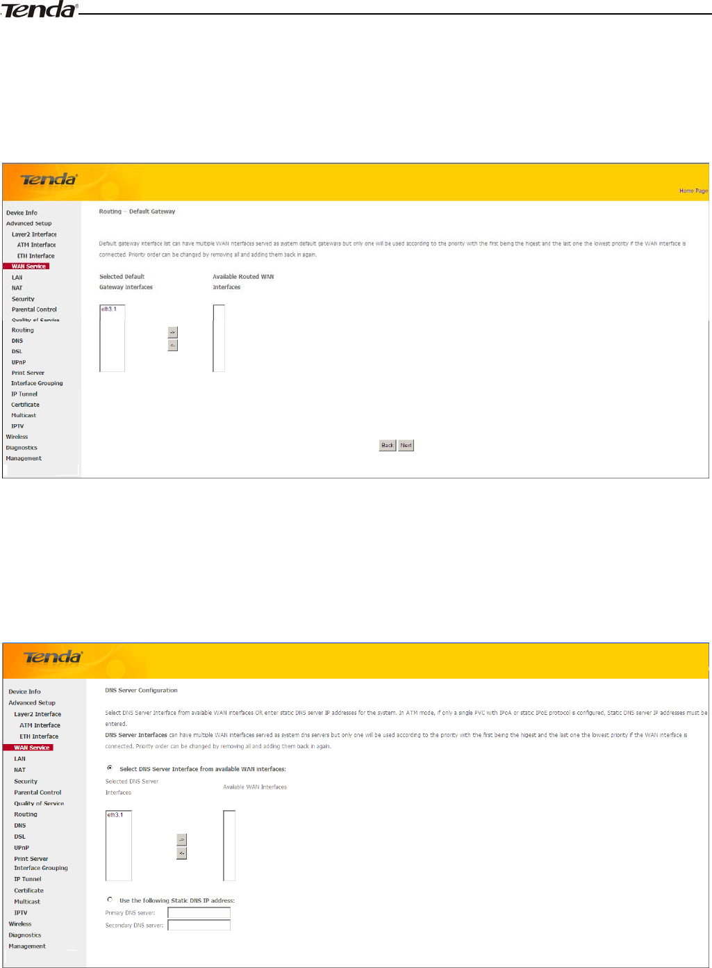
Here you can configure the NAT settings. If you are unsure about the options, please keep the default settings and then
click Next.
Here you can configure the WAN gateway address. Default gateway interface list can have multiple WAN interfaces
served as system default gateways but only one will be used according to the priority with the first being the higest and
the last one the lowest priority if the WAN interface is connected. Priority order can be changed by removing all and
adding them back in again.
If you are unsure about the options, please keep the default settings and then click Next.
Here you can configure the WAN DNS address:
-Click the Select DNS Server Interface from available WAN interfaces option
-OR select the Use the following Static DNS IP address option and enter static DNS server IP addresses for the system
And then click Next.
_________________________________________________________________________________________________
Wireless Modem Router User Guide
- 32 -
Note:
1.DNS Server Interfaces can have multiple WAN interfaces served as system dns servers but only one will be used
according to the priority with the first being the higest and the last one the lowest priority if the WAN interface is
connected. Priority order can be changed by removing all and adding them back in again.
2. In ATM mode, if only a single PVC with IPoA or static IPoE protocol is configured, Static DNS server IP addresses
must be entered.
3. If you cannot locate the static DNS server IP information, ask your ISP to provide it.
_________________________________________________________________________________________________
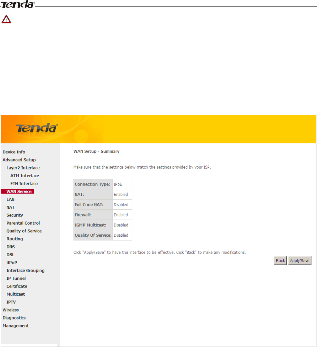
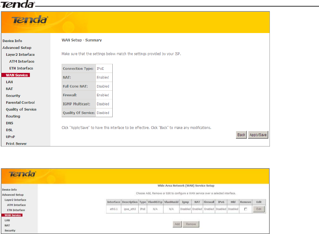
Here you can view your configurations. Click Apply/Save to save your settings if everything is correctly set.
Wireless Modem Router User Guide
- 33 -
When the IPoE connection is successful, you can access Internet.
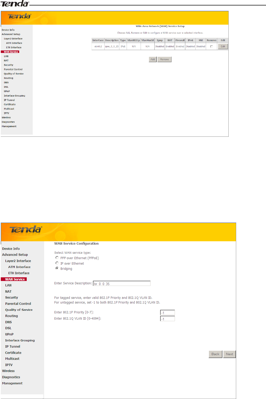
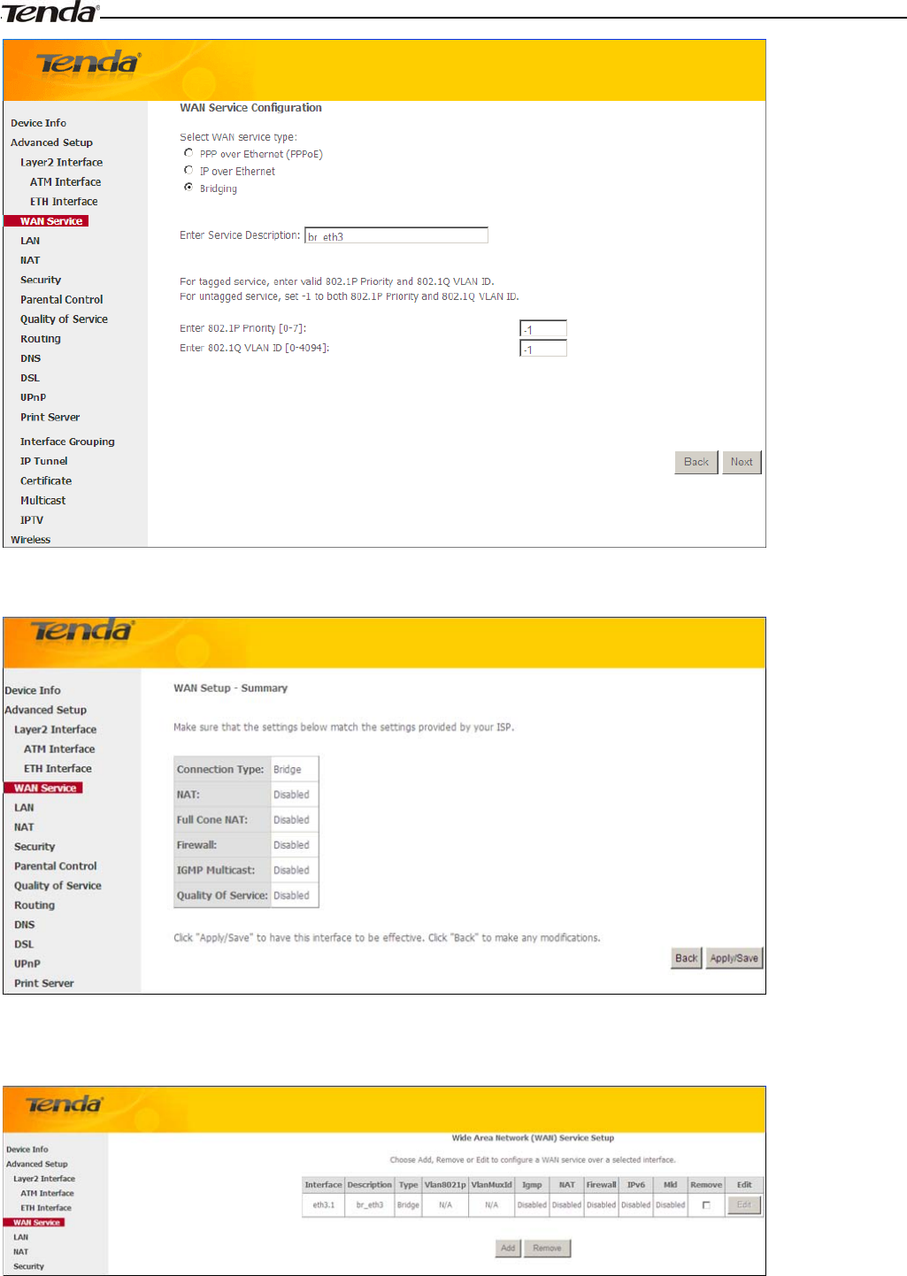
Bridging
If you wish to iniate a dialup directly from your PC for Internet access or enjoy the entire Internet connection (instead of
sharing it with others), you can use the Bridging DSL link type and create a dialup program on your PC.
If you have selected the EoA from the ATM Interface screen in Layer2 Interface, you will see the screen below when
you click the WAN Service tab, select the configured interface and click Next.
Wireless Modem Router User Guide
- 34 -
The Enter Service Description field is optional. We recommend that you keep it unchanged from default and click
Next.
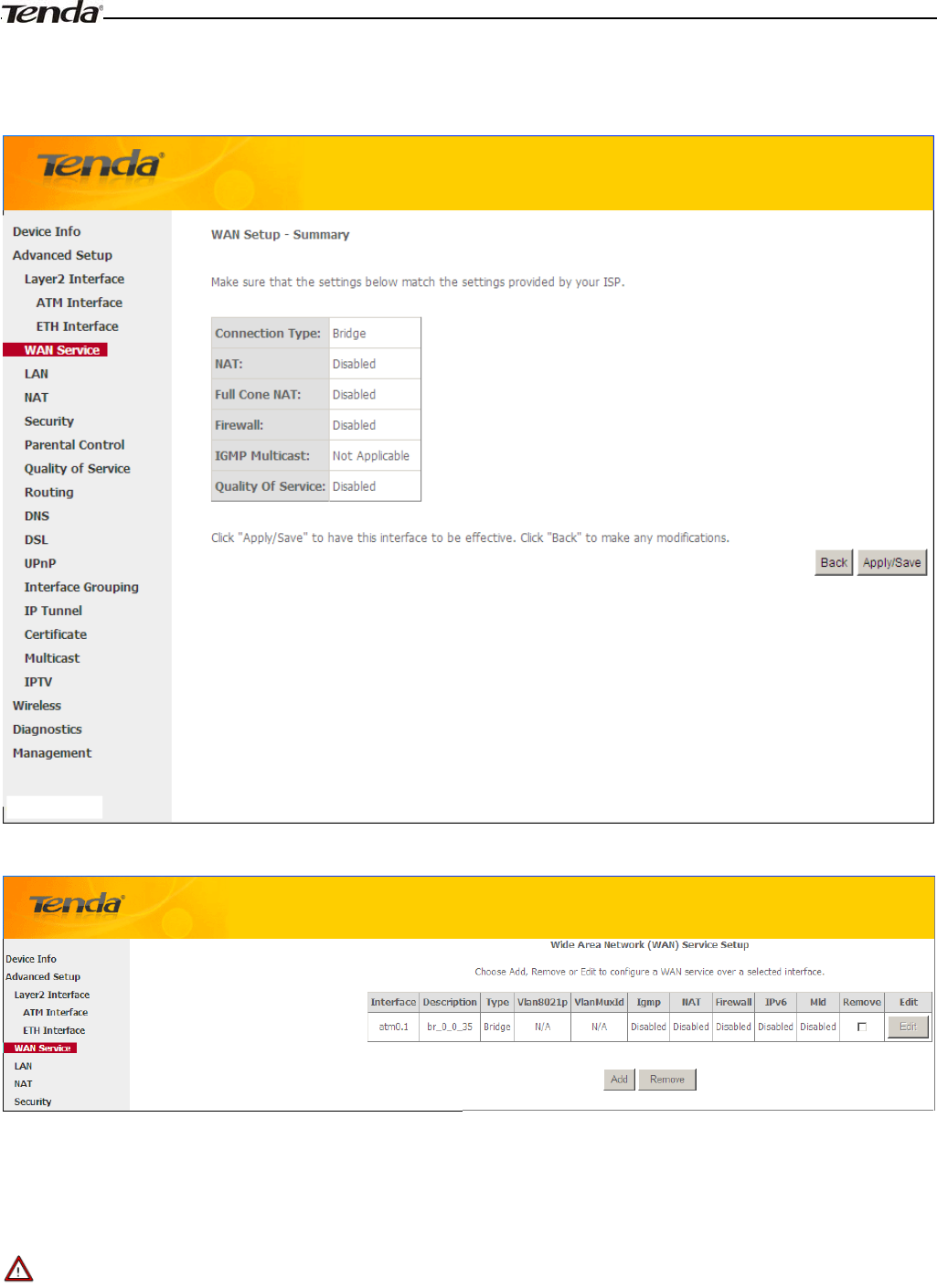
Here you can view your configurations. Click Apply/Save to save your settings if everything is correctly set.
When the bridging connection is successful, you can access Internet.
_________________________________________________________________________________________________
Note:
To configure multiple WAN connections, simply configure multiple ATM interfaces and then follow the instructions
above.
_________________________________________________________________________________________________
Wireless Modem Router User Guide
- 35 -
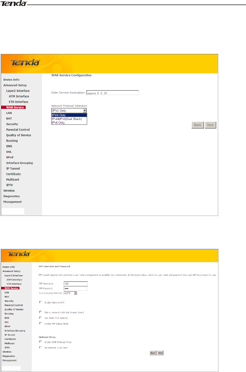
PPPoA
If you have selected the PPPoA from the ATM Interface screen in Layer2 Interface, you will see the screen below
when you click the WAN Service tab, select the configured interface and click Next.
1. Edit the Enter Service Description. This field is optional. We recommend that you keep the default.
2. Select a network protocol: IPv4, IPv6 or IPv4 & IPv6 (dual stack).
3. Click Next.
Wireless Modem Router User Guide
- 36 -
¾PPP User Name: This is for logging in to your ISP. If you cannot locate this information, ask your ISP to provide
it.
¾PPP Password: This is for logging in to your ISP. If you cannot locate this information, ask your ISP to provide it.
¾Authentication Method: This is used by ISP to authenticate the client that attempts to connect. If you are not sure,
consult your ISP or select Auto.
¾Dial on demand: Connect to ISP only when there is traffic transmission. This saves your broadband Internet
service bill.
¾Enable PPP Debug Mode: Only enable this feature if supported by your ISP.
¾Bridge PPPoE Frames Between WAN and Local Ports: If enabled, PPPoE dialup frame from LAN side will
directly egress the WAN port without modification.
¾Multicast Proxy: If enabled, the router will use multicast proxy.
If you are not sure about the options on this screen, simply enter your ISP user name and password and leave the other
options unchanged from defaults. Click Next to enter the following screen.
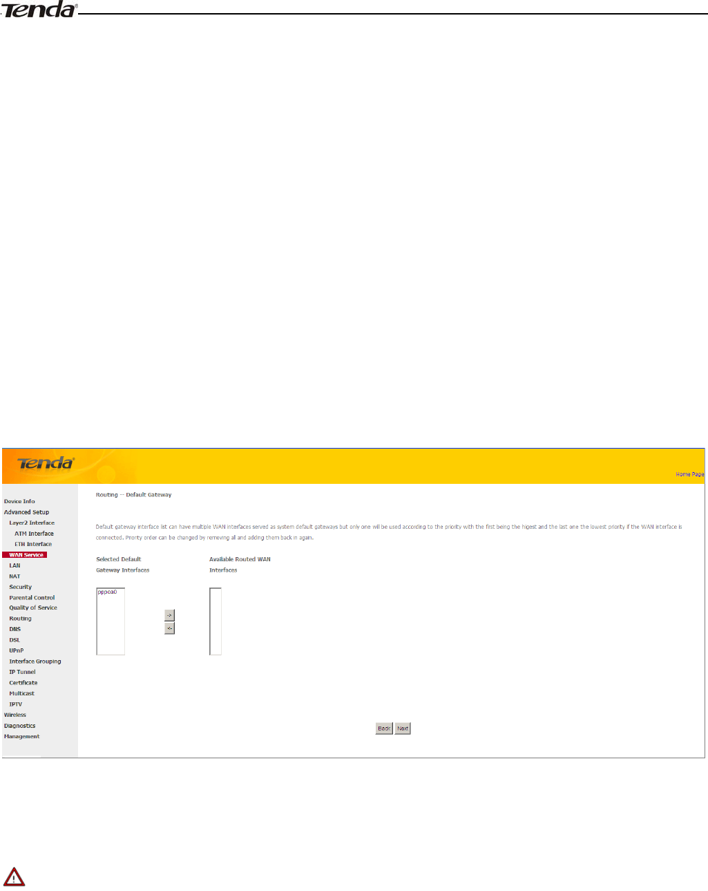
WAN gateway
Here you can configure the WAN gateway address. After you configure it click Next. The default setting is
recommended.
_________________________________________________________________________________________________
Note:
Default gateway interface list can have multiple WAN interfaces served as system default gateways but only one will be
used according to the priority with the first being the higest and the last one the lowest priority if the WAN interface is
connected. Priority order can be changed by removing all and adding them back in again.
_________________________________________________________________________________________________
Wireless Modem Router User Guide
- 37 -
WAN DNS
Here you can configure the WAN DNS address:
-Click the Select DNS Server Interface from available WAN interfaces option
-OR select the Use the following Static DNS IP address option and enter static DNS server IP addresses for the system
And then click Next.
_________________________________________________________________________________________________
Note:
1.DNS Server Interfaces can have multiple WAN interfaces served as system dns servers but only one will be used
according to the priority with the first being the higest and the last one the lowest priority if the WAN interface is
connected. Priority order can be changed by removing all and adding them back in again.
2. In ATM mode, if only a single PVC with IPoA or static IPoE protocol is configured, Static DNS server IP addresses
must be entered.
3. If you cannot locate the static DNS server IP information, ask your ISP to provide it.
_________________________________________________________________________________________________
Wireless Modem Router User Guide
- 38 -
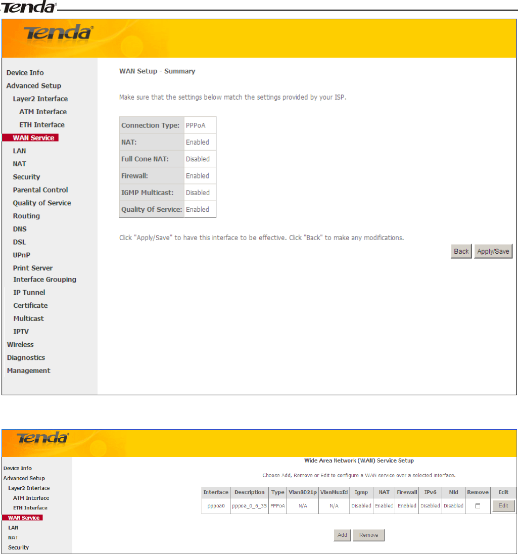
Here you can view your configurations. Click Apply/Save to save your settings if everything is correctly set.
When the PPPoA connection is successful, you can access Internet.
IPoA
If you have selected the IPoA from the ATM Interface screen in Layer2 Interface, you will see the screen above when
you click the WAN Service tab, select the configured interface and click Next.
Wireless Modem Router User Guide
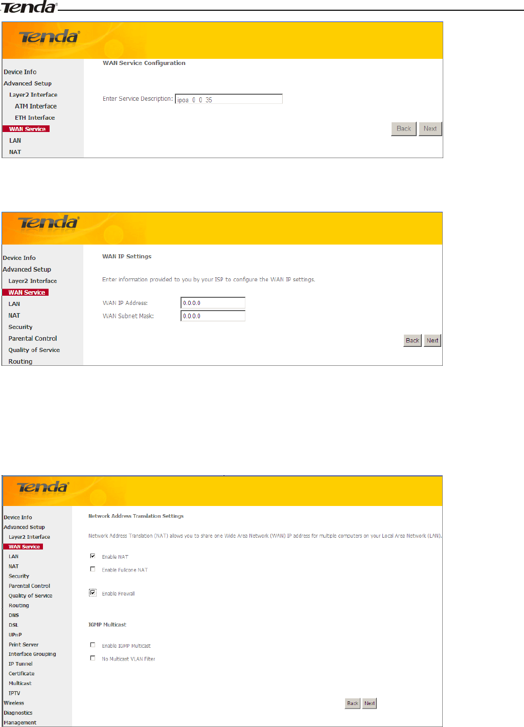
- 39 -
1. Edit the Enter Service Description. This field is optional. We recommend that you keep the default.
2. Click Next.
¾WAN IP Address: The Internet IP address provided by your ISP for accessing Internet.
¾WAN Subnet Mask: The subnet mask address provided by your ISP for accessing Internet.
Enter the WAN IP address and subnet mask assigned by your ISP. This information should have been provided to you by
your ISP. If you cannot locate this information, ask your ISP to provide it. And then click Next to enter the following
screen.
If you are unsure about the options on the screen above, keep the defaults and click Next.
Wireless Modem Router User Guide
- 40 -
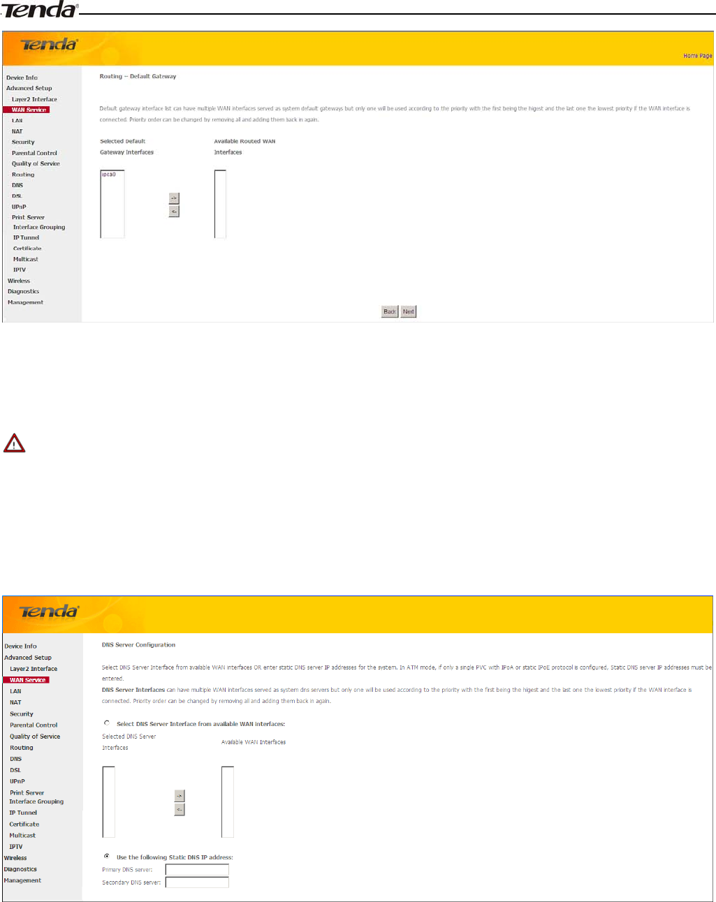
Here you can configure the WAN gateway address. After you configure it click Next. The default setting is
recommended.
______________________________________________________________________________________________
Note:
Default gateway interface list can have multiple WAN interfaces served as system default gateways but only one will be
used according to the priority with the first being the higest and the last one the lowest priority if the WAN interface is
connected. Priority order can be changed by removing all and adding them back in again.
______________________________________________________________________________________________
Here you can configure the WAN DNS address:
-Click the Select DNS Server Interface from available WAN interfaces option
-OR select the Use the following Static DNS IP address option and enter static DNS server IP addresses for the system
And then click Next to enter the following screen.
Wireless Modem Router User Guide
- 41 -
_________________________________________________________________________________________________
Note:
1. DNS Server Interfaces can have multiple WAN interfaces served as system dns servers but only one will be used
according to the priority with the first being the higest and the last one the lowest priority if the WAN interface is
connected. Priority order can be changed by removing all and adding them back in again.
2. In ATM mode, if only a single PVC with IPoA or static IPoE protocol is configured, Static DNS server IP addresses
must be entered.
3. If you cannot locate the static DNS server IP information, ask your ISP to provide it.
_________________________________________________________________________________________________
Confirm your settings and then click Apply/Save to apply and save your settings. Your settings will then be displayed on
the screen below:
To setup WAN Service for ETH Interface
If you select and configured the ETH Interface (Ethernet uplink), follow steps below to configure the WAN service:
Two Internet connections: PPP over Ethernet (PPPoE) and IP over Ethernet (IPoE) are available in the Ethernet uplink
Wireless Modem Router User Guide
- 42 -
mode.
_________________________________________________________________________________________________
Tip:
eth0, eth1, eth3 and eth3 respectively represent the LAN port1, LAN port2, LAN port3 and LAN port4 of the device.
_________________________________________________________________________________________________
PPP over Ethernet (PPPoE)
Click Advanced Setup -> WAN Service -> Add, select the configured interface and then click Next to enter the
following screen.
1. Select PPPoE.
2. Edit the Enter Service Description. This field is optional. We recommend that you keep the default.
3. Select a network protocol: IPv4, IPv6 or IPv4 & IPv6 (dual stack).
4. Click Next.
_________________________________________________________________________________________________
Note:
If you select IPv6 or IPv4 & IPv6 (dual stack), skip to IPv6.
_________________________________________________________________________________________________
Wireless Modem Router User Guide
- 43 -
PPP User Name: This is for logging in to your ISP. If you cannot locate this information, ask your ISP to provide
it.
PPP Password: This is for logging in to your ISP. If you cannot locate this information, ask your ISP to provide
it.
PPPoE Service Name: This information is provided by your ISP. Only enter it if instructed by your ISP.
Authentication Method: This is used by ISP to authenticate the client that attempts to connect. If you are not sure,
consult your ISP or select Auto.
Clone MAC: Clicking this button copies the MAC address of your PC to the router. Many broadband ISPs restrict
access by allowing traffic only from the MAC address of your broadband modem, but some ISPs additionally
register the MAC address of the network interface card in your computer when your account is first opened. They
then accept traffic only from the MAC address of that computer. If so, configure your router to “clone” the MAC
address from the authorized computer.
Dial on demand: Connect to ISP only when there is traffic transmission. This saves your broadband Internet
service bill.
PPP IP extension: If enabled, all the IP addresses in outgoing packets including management packets on the WAN
port will be changed to the device's WAN IP address. Only change the default settings if necessary.
Enable PPP Debug Mode: Only enable this feature if supported by your ISP.
Bridge PPPoE Frames Between WAN and Local Ports: If enabled, PPPoE dialup frame from LAN side will
directly egress the WAN port without modification.
Multicast Proxy: If enabled, the router will use multicast proxy.
If you are not sure about the options on this screen, simply enter your ISP user name and password and leave the other
options unchanged from defaults. Click Next.
IPv6
If you select IPv4 as the network protocol, skip this section.
Wireless Modem Router User Guide
- 44 -
1. Check Launch Dhcp6c for Prefix Delegation (IAPD).
2. If your ISP is using stateful DHCPv6, check Launch Dhcp6c for Address Assignment (IANA) also. Or configure
a static IP address.
3. Click Next -> Next -> Apply/Save.
Wireless Modem Router User Guide
- 45 -
WAN Gateway
Here you can configure the WAN gateway address. After you configure it click Next. The default setting is
recommended.
WAN DNS
Here you can configure the WAN DNS address. After you configure it click Next. The default setting is recommended
if you cannot locate this information.
Here you can configure the WAN DNS address:
-Click the Select DNS Server Interface from available WAN interfaces option
-OR select the Use the following Static DNS IP address option and enter static DNS server IP addresses for the system
And then click Next.
Wireless Modem Router User Guide
- 46 -
Here you can view your configurations. Click Apply/Save to save your settings if everything is correctly set.
When the PPPoE connection is successful, you can access Internet.
IP over Ethernet (IPoE)
If your ISP uses DHCP to assign your IP address or if your ISP assigns you a static (fixed) IP address, IP subnet mask
and the gateway IP address, you need to select the IP over Ethernet (IPoE).
Click Advanced Setup -> WAN Service -> Add, select the configured interface and then click Next to enter the
following screen.
Wireless Modem Router User Guide
- 47 -
1. Select IPoE.
2. Edit the Enter Service Description. This field is optional. We recommend that you keep the default.
3. Select a network protocol: IPv4, IPv6 or IPv4 & IPv6 (dual stack).
4. Click Next.
_________________________________________________________________________________________________
Note:
If you select IPv6 or IPv4 & IPv6 (dual stack), skip to IPv6.
_________________________________________________________________________________________________
Obtain an IP address automatically: This allows the router to automatically acquire IP information from your ISP
or your existing networking equipment.
Wireless Modem Router User Guide
- 48 -
Use the following Static IP address: This allows you to specify the Static IP information provided by your ISP or
that corresponds with your existing networking equipment.
WAN IP Address: The Internet IP address provided by your ISP for accessing Internet.
WAN Subnet Mask: The subnet mask address provided by your ISP for accessing Internet.
WAN gateway IP Address: The gateway IP address provided by your ISP for accessing Internet.
Enter the IP address/ subnet mask/gateway IP address provided by your ISP or select Obtain an IP address
automatically and then click the Next button.
IPv6
If you select IPv4 as the network protocol, skip this section.
To obtain an IP address automatically:
1. Select Obtain an IP address automatically.
2. Check Launch Dhcp6c for Prefix Delegation (IAPD).
3. If your ISP is using stateful DHCPv6, check Launch Dhcp6c for Address Assignment (IANA) also.
4. Click Next -> Next -> Apply/Save.
Wireless Modem Router User Guide
- 49 -
To configure a static IPv6 address
1. Select Use the following Static IPv6 address.
2. Configure WAN IPv6 Address/Prefix Length and WAN Next-Hop IPv6 Address.
Wireless Modem Router User Guide
- 50 -
3. Click Next -> Next to enter the screen below.
4. Select Use the following Static IPv6 DNS address and manually enter the DNS server address. If you have two
DNS server addresses, enter the second also.
5. Click Next -> Apply/Save.
NAT
Wireless Modem Router User Guide
- 51 -
Here you can configure the NAT. If you are not an advanced user we recommend you to keep the default settings and
then click Next.
WAN Gateway
Here you can configure the WAN gateway address. After you configure it click Next. The default setting is
recommended.
WAN DNS
Here you can configure the WAN DNS address. After you configure it click Next. The default setting is recommended if
you cannot locate this information.
Here you can configure the WAN DNS address:
-Click the Select DNS Server Interface from available WAN interfaces option
-OR select the Use the following Static DNS IP address option and enter static DNS server IP addresses for the system
And then click Next.
Wireless Modem Router User Guide
- 52 -
Here you can view your configurations. Click Apply/Save to save your settings if everything is correctly set.
When the IPoE connection is successful, you can access Internet.
Bridging
If you wish to iniate a dialup directly from your PC for Internet access or enjoy the entire Internet connection (instead of
sharing it with others), you can select the Bridging and create a dialup program on your PC.
Click Advanced Setup -> WAN Service -> Add, select the configured interface and then click Next to enter the
following screen.
Wireless Modem Router User Guide
- 53 -
Edit the Service Description, which is optional. And then click Next.
Here you can view your configurations. Click Apply/Save to save your settings if everything is correctly set.
When the connection is successful, you can access Internet.
Wireless Modem Router User Guide
- 54 -
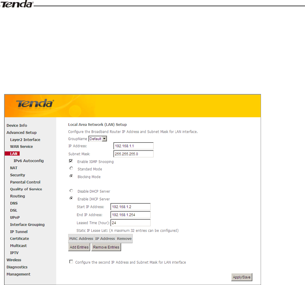
4.2.3 LAN Setup
Here you can configure the LAN IP Address and Subnet Mask. This IP address is to be used to access the device’s
settings through a web browser. Be sure to make a note of any changes you apply to this page.
IPv4
IP Address: The device's LAN IP address. The default setting is 192.168.1.1.
Subnet Mask: The LAN subnet mask of the device. Combined with the IP address, the IP Subnet Mask allows a
device to know which other addresses are local to it, and which must be reached through a gateway or modem
router. You can change the subnet mask to fit your network.
Enable IGMP Snooping: Check to enable the IGMP Snooping feature and select either of the following two odes:
Configure the second IP Address and Subnet Mask for LAN interface: If you want to configure two IP
addresses for the LAN interface, you can check this option and enter the second IP Address and Subnet Mask
manually.
Disable DHCP Server: Click to disable the DHCP Server.
Enable DHCP Server: Click to enable the DHCP Server.
Start IP Address: Specify the start of the range for the pool of IP addresses in the same subnet as the router.
End IP Address: Specify the end of the range for the pool of IP addresses in the same subnet as the router.
Leased Time: The lease time is a time length that the IP address is assigned to each device before it is refreshed.
Static IP Lease List: Displays a list of devices with reserved static IP addresses.
Add Entries: Click to add a static IP lease entry. A maximum 32 entries can be configured.
Remove Entries: Click to remove a static IP lease entry.
Wireless Modem Router User Guide
- 55 -
Apply/Save: After you configure all the needed settings, click this button to apply and save them.
_________________________________________________________________________________________________
Tip:
DHCP (Dynamic Host Configuration Protocol) assigns an IP address to each device on the LAN/private network. When
you enable the DHCP Server, the DHCP Server will automatically allocate an unused IP address from the IP address
pool specified in this screen to the requesting device as long as the device is set to "Obtain an IP Address Automatically".
By default, the router functions as a DHCP server.
_________________________________________________________________________________________________
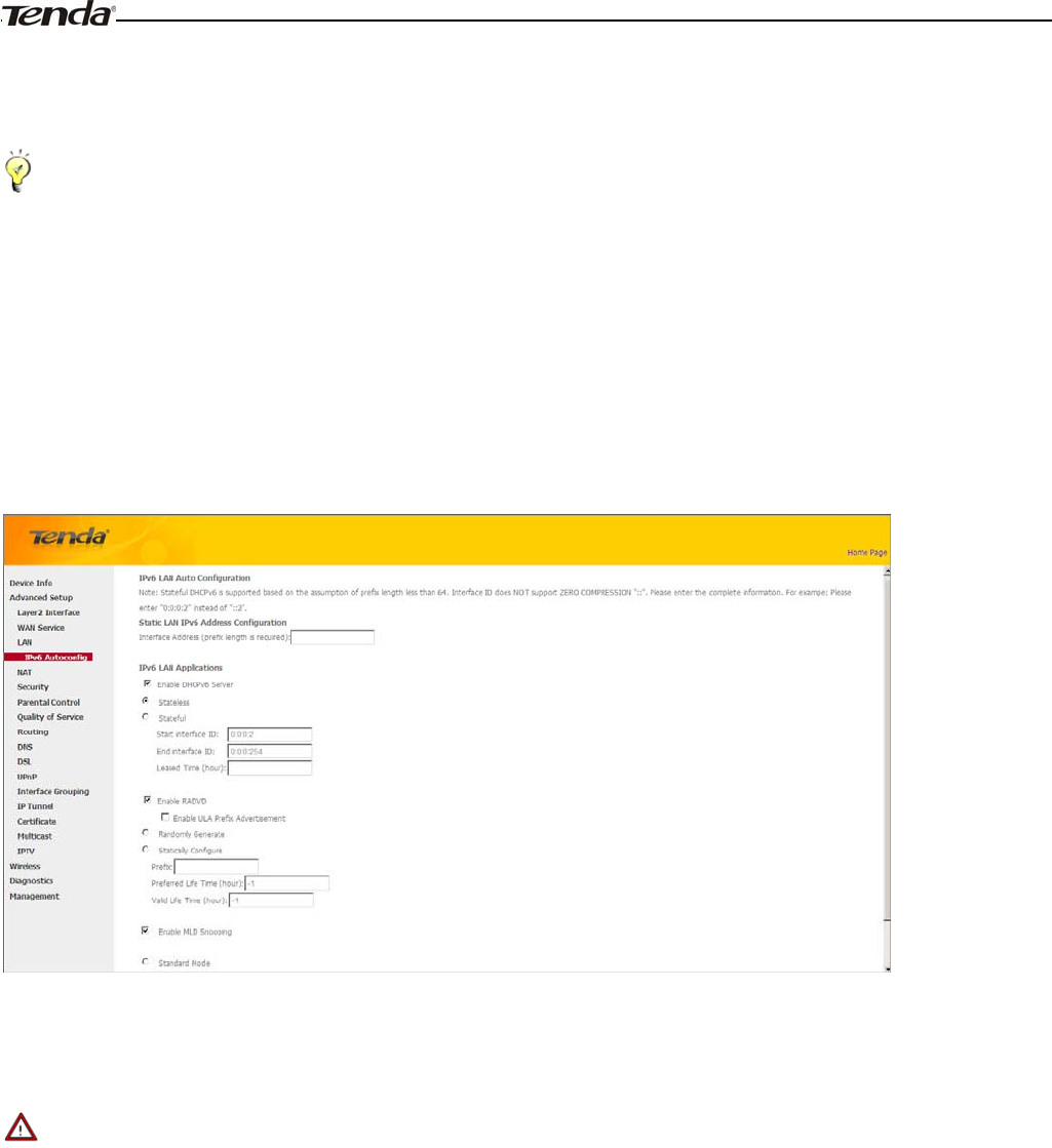
IPv6 Autoconfig
Static LAN IPv6 Address Configuration
Interface Address (prefix length is required): Enter the interface address.
_________________________________________________________________________________________________
Note:
1. IPv6 address can only be Aggregatable Global Unicast Addresses and Unique Local Address. Link-Local Unicast
Addresses and Multicast Addresses are not permitted.
2. The IPv6 address must be entered with a prefix length.
_________________________________________________________________________________________________
IPv6 LAN Applications
Enable DHCPv6 Server
˖
Check to enable the DHCPv6 Server.
Stateless: If selected, IPv6 clients will generate IPv6 addresses automatically based on the Prefix Delegation's
IPv6 prefix and their own MAC addresses.
Stateful: Stateful DHCPv6 is supported based on the assumption of prefix length less than 64. Select this
option and configure the start/end interface ID and leased time. The router will automatically assign IPv6

Wireless Modem Router User Guide
- 56 -
addresses to IPv6 clients.
Leased Time (hour): The lease time is a time length that the IP address is assigned to each device before it is
refreshed.
Start interface ID/End interface ID: Specify the start/end interface ID Interface ID does NOT support ZERO
COMPRESSION "::". Please enter the complete information. For exampe: Please enter "0:0:0:2" instead of
"::2".
Enable RADVD: The RADVD (Router Advertisement Daemon) implements link-local advertisements of IPv6
router addresses and IPv6 routing prefixes using the Neighbor Discovery Protocol (NDP) and is used by system
administrators in stateless autoconfiguration methods of network hosts on Internet Protocol version 6 networks.
Check the checkbox to enable the RADVD.
Enable ULA Prefix Advertisement: If enabled, the router will advertise ULA prefix periodically
Randomly Generate: If selected, address prefix can be automatically generated.
Statically Configure: If you select this option, you need to manually configure the address prefix and life
time.
Prefix: Specify the prefix.
Preferred Life Time (hour): Specify the preferred life time in hour.
Valid Life Time (hour): Specify the valid life time in hour.
Enable MLD Snooping: MLD is used by IPv6 routers for discovering multicast listeners on a directly attached link.
If disabled on layer2 devices, IPv6 multicast data packets will be broadcast on the entire layer2; if enabled, these
packets will be multicast to only specified recipient instead of being broadcast on the entire layer2.
_________________________________________________________________________________________________
Tip:
If you change the LAN IP address of the device, you will lose your connection to the device. You must type the new IP
address into your browser address field to log in to the device and set all gateway addresses of the LAN PCs to this new
address to access Internet. Be sure to write the new address on a sticky label and attach it to the bottom of the unit. You
will need the new address to log in to the device in the future.
_________________________________________________________________________________________________
4.2.4 NAT
This section explais the following:
•Virtual Server
•Port Triggering
•DMZ Host
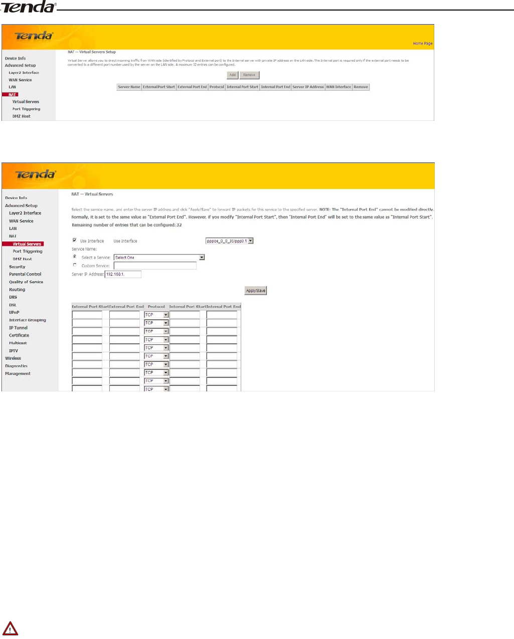
Virtual Server
The Virtual Server is useful for web servers, ftp servers, e-mail servers, gaming and other specialized Internet
applications. When you enable the Virtual Server, the communication requests from the Internet to your router’s WAN
port will be forwarded to the specified LAN IP address.
Wireless Modem Router User Guide
- 57 -
To enter the virtual server screen, click NAT -> Virtual Server and then click the Add button to add rules.
Use Interface: Select a WAN connection to which you wish to apply the rules. When there is only one WAN
connection available, the rules will be automatically applied to it.
Service Name:
-Select a Service option: Allows you to select an existing service from the drop-down list.
- Custom Service: Allows you to customize a service.
Server IP Address: Enter the IP address of your local computer that will provide this service.
External Starting Port and External Ending Port: These are the starting number and ending number for the
public ports at the Internet interface.
Protocol: Select the protocol from the Protocol drop-down list. If you are unsure, select TCP/UDP.
Internal Starting Port and Internal Ending Port: These are the starting number and ending number for the ports
of a computer on the router’s local area network (LAN).
_________________________________________________________________________________________________
Note:
If you have enabled the UPnP functionality on both the router and your PC that is attached to one of the LAN port on the
router, you will be prompted on the Virtual Server page that the UPnP interface is being used.
_________________________________________________________________________________________________
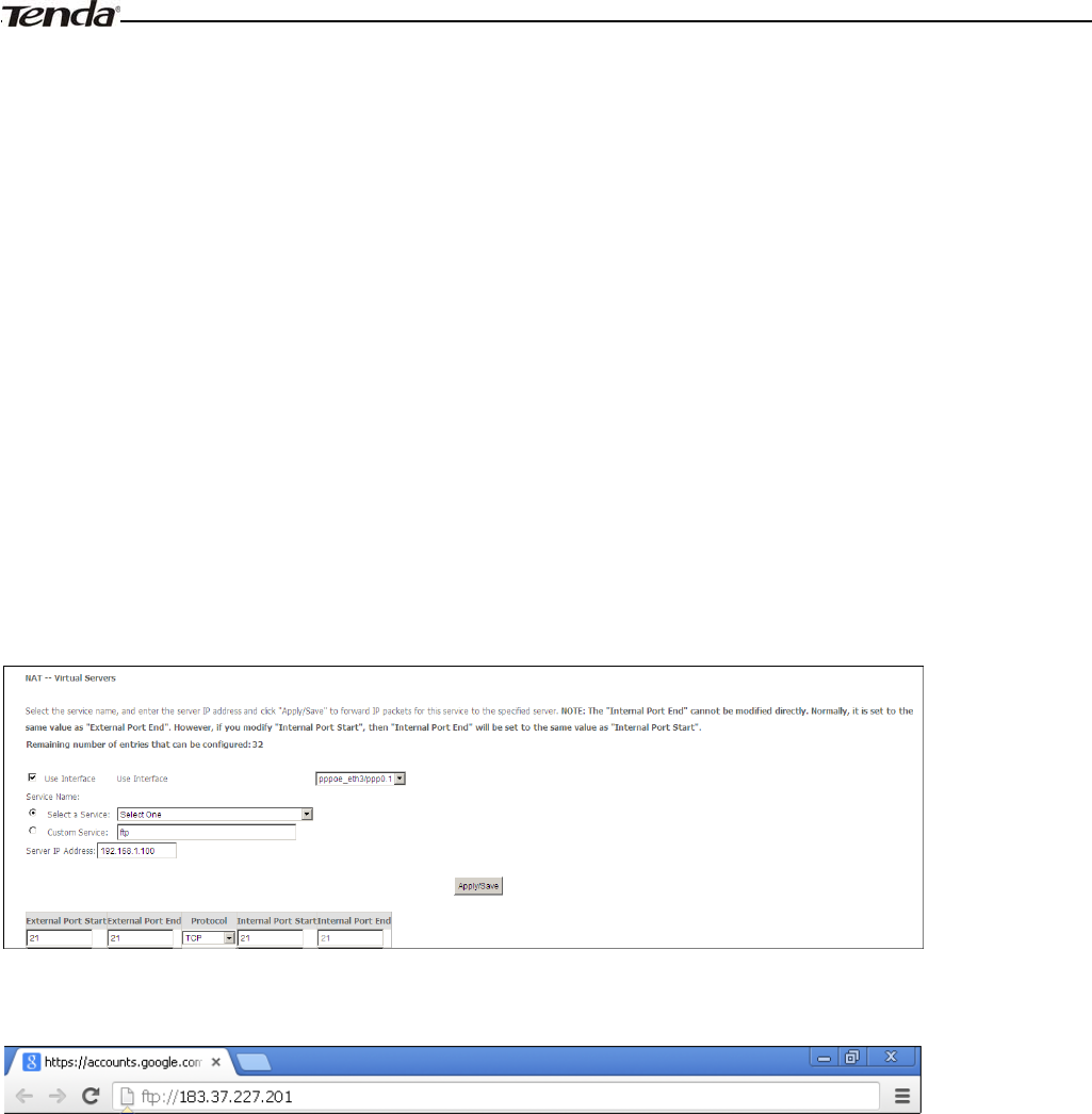
Application Example:
You have set up two servers on your LAN side:
- An FTP server (using the default port number of 21) at the IP address of 192.168.1.100
- A web server (using the default port number of 80) at the IP address of 192.168.1.110
Wireless Modem Router User Guide
- 58 -
And want your friends on Internet to access the FTP server and web server on default ports. To access your FTP or web
server from the Internet, a remote user has to know the Internet IP address or Internet name of your router, such as
www.tendacn.com. In this example, we assume the Internet IP address of your router is 183.37.227.201. Then follow
instructions below:
To configure the router to make your local FTP server public:
1. Click NAT -> Virtual Server to enter it and then click the Add button.
2. - Select FTP that you wish to host on your network from the Select a Service drop-down list. The port number (21)
used by this service will then be automatically populated.
- Or if you wish to define the service yourself, enter a descriptive name in the Custom Service, say My FTP, and
then manully enter the port number (21) used by this service in the Internal Starting Port, Internal Ending Port,
External Starting Port and External Ending Port fields.
3. Select a protocol from the Protocol drop-down list. If you are unsure, select TCP/UDP.
4. In the Server IP Address field, enter the last digit of the IP address of your local computer that offers this service.
Here in this example, we enter 192.168.1.100.
5. Click the Apply/Save button.
6. Your friends on Internet will then be able to access your FTP server simply by entering "ftp://183.37.227.201" in his
browser.
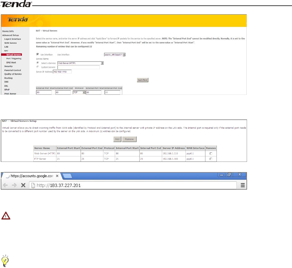
To configure your router to make your local web server public:
1. Click NAT -> Virtual Server to enter it and then click the Add button.
2. - Select Web Server (HTTP) that you wish to host on your network from the Select a Service drop-down list. The
port number (80) used by this service will then be automatically populated.
- Or if you wish to define the service yourself, enter a descriptive name in the Custom Service, say My Web Server
(HTTP), and then manully enter the port number (80) used by this service in the Internal Starting Port, Internal
Ending Port, External Starting Port and External Ending Port fields.
3. Select a protocol from the Protocol drop-down list. If you are unsure, select TCP/UDP.
4. In the Server IP Address field, enter the last digit of the IP address of your local computer that offers this service.
Here in this example, we enter 192.168.1.110.
5. Click the Apply/Save button.
Wireless Modem Router User Guide
- 59 -
6. Now you can view your configurations as seen in the screenshot below. Your friends on Internet will then be able to
access the web server simply by entering "http://183.37.227.201" in his browser.
_________________________________________________________________________________________________
Note:
The "Internal Port End" cannot be modified directly. Normally, it is set to the same value as "External Port End".
However, if you modify "Internal Port Start", then "Internal Port End" will be set to the same value as "Internal Port
Start".
Tip:
If the service or game you wish to host on your network is not included in the list, manually add it in the Custom Service
field and then add the port number used by it to the Internal Starting Port, Internal Ending Port, External Starting
Port and External Ending Port fields.
_________________________________________________________________________________________________
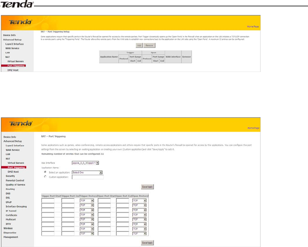
Port Triggering
Some applications such as games, video conferencing, remote access applications and others require that specific ports in
the Router's firewall be opened for access by the applications. Port Trigger dynamically opens up the 'Open Ports' in the
firewall when an application on the LAN initiates a TCP/UDP connection to a remote party using the 'Triggering Ports'.
The Router allows the remote party from the WAN side to establish new connections back to the application on the LAN
side using the 'Open Ports'.
Wireless Modem Router User Guide
- 60 -
To enter the Port Triggering screen, click NAT -> Port Triggering and then click the Add button to add rules.
You can configure the port settings from this screen by selecting an existing application or creating your own (Custom
application) and click "Save/Apply" to add it.
Use Interface: Select a WAN connection to which you wish to apply the rules. When there is only one WAN
connection available, the rules will be automatically applied to it.
Application Name: Two options are available:
- Select an application
- Custom application
Trigger Port Start/Trigger Port End: The port range for an application to initiate connections.
Trigger Protocol: Select the protocol from the drop-down list. If you are unsure, select TCP/UDP.
Open Port Start/ Open Port End: These are the starting number and ending number for the ports that will be
automatically opened by the built-in firewall when connections initiated by an application are established.
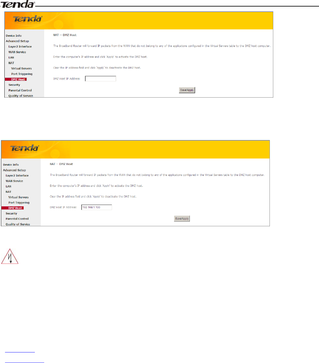
DMZ Host
The default DMZ (De-Militarized Zone) host feature is helpful when you are using some online games and
videoconferencing applications that are not compatible with NAT (Network Address Translation).
Wireless Modem Router User Guide
- 61 -
DMZ Host IP Address: The IP Address of the device for which the router’s firewall will be disabled. Be sure to assign a
static IP Address to that device. The DMZ host should be connected to a LAN port of the device. Be sure to assign a
static IP address to that DMZ host.
_________________________________________________________________________________________________
Warning!
DMZ servers pose a security risk. A computer designated as the DMZ server loses much of the protection of the firewall
and is exposed to exploits from the Internet.
_________________________________________________________________________________________________
4.2.5 Security
This section explains the following information:
•IP Filtering
•MAC Filtering
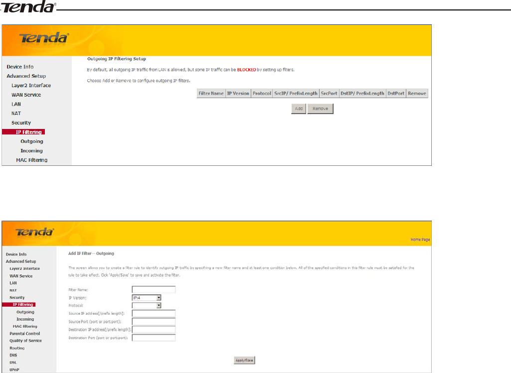
IP Filtering
Outgoing IP Filtering Setup
By default, all outgoing IP traffic from LAN is allowed, but some IP traffic can be BLOCKED by setting up filters.
Choose Add or Remove to configure outgoing IP filters.
Wireless Modem Router User Guide
- 62 -
Choose Add to enter the following screen:
This screen allows you to create a filter rule to identify outgoing IP traffic by specifying a new filter name and at least
one condition below. All of the specified conditions in this filter rule must be satisfied for the rule to take effect. Click
'Apply/Save' to save and activate the filter.
Filter Name: Enter a descriptive filtering name.
IP Version: Select either IPv4 or IPv6.
Protocol: TCP/UDP, TCP, UDP and ICMP are available for your option.
Source IP address [/prefix length]: Enter the LAN IP address to be filtered.
Source Port (port or port: port): Specify a port number or a range of ports used by LAN PCs to access Internet. If
you are unsure, leave it blank.
Destination IP address [/prefix length]: Specify the external network IP address to be accessed by specified LAN
PCs.
Destination Port (port or port:port):Specify a port number or a range of ports used by LAN PCs to access external
network.
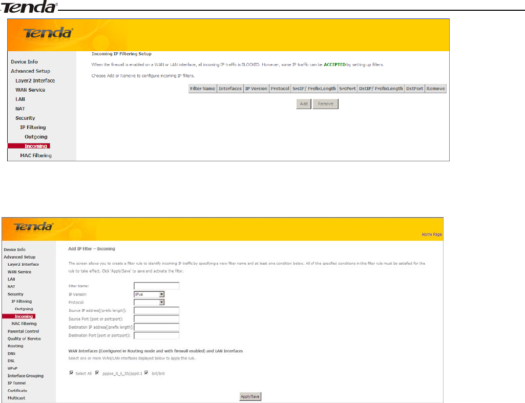
Incoming IP Filtering Setup
When the firewall is enabled on a WAN or LAN interface, all incoming IP traffic is BLOCKED. However, some IP
traffic can be ACCEPTED by setting up filters.
Choose Add or Remove to configure incoming IP filters.
Wireless Modem Router User Guide
- 63 -
Click Add to enter the following screen:
This screen allows you to create a filter rule to identify incoming IP traffic by specifying a new filter name and at least
one condition below. All of the specified conditions in this filter rule must be satisfied for the rule to take effect. Click
Apply/Save to save and activate the filter.
IP Version: Select either IPv4 or IPv6.
Protocol: TCP/UDP, TCP, UDP and ICMP are available for your option.
Source IP address [/prefix length]: Enter the Internal IP address [/prefix length] to be filtered.
Source Port (port or port: port): Specify a port number or a range of ports used by PCs from external network to
access your internal network.
Destination IP address [/prefix length]: Specify the internal network IP address [/prefix length] to be accessed by
the specified PCs from external network.
Destination Port (port or port:port):Specify a port number or a range of ports used by PCs from external network
to access your internal network.
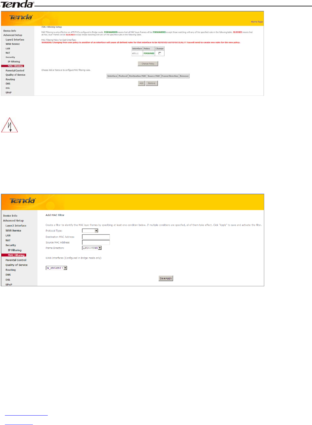
MAC Filtering
A bridge WAN service is needed to configure this service.
MAC Filtering is only effective on ATM PVCs configured in Bridge mode. FORWARDED means that all MAC layer
frames will be FORWARDED except those matching with any of the specified rules in the following table. BLOCKED
means that all MAC layer frames will be BLOCKED except those matching with any of the specified rules in the
following table.
Choose Add or Remove to configure MAC filtering rules.
Wireless Modem Router User Guide
- 64 -
_________________________________________________________________________________________________
Warning!
Changing from one policy to another of an interface will cause all defined rules for that interface to be REMOVED
AUTOMATICALLY! You will need to create new rules for the new policy.
_________________________________________________________________________________________________
Click Add to enter the following screen:
Here you can create a filter to identify the MAC layer frames by specifying at least one condition below. If multiple
conditions are specified, all of them take effect. Click Save/Apply to save and activate the filter.
Protocol Type: Select a protocol type from the drop-down list.
Destination MAC Address: Enter the destination MAC address apply the MAC filtering rule to which you wish to
apply the MAC filtering rule.
Source MAC Address: Enter the source MAC address to which you wish to apply the MAC filtering rule.
Frame Direction: Select a frame direction from the drop-down list.
WAN Interfaces: Select a WAN interface from the drop-down list.
4.2.6 Parental Control
This section explains the following information:
•Time Restriction
•URL Filter
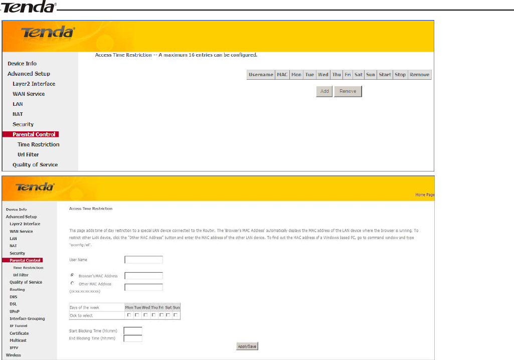
Time Restriction
Click Parental Control -> Time Restriction -> Add to enter the following screen.
Wireless Modem Router User Guide
- 65 -
Here you can add time of day restriction that an attached LAN device can access Internet.
The 'Browser's MAC Address' automatically displays the MAC address of the LAN device where the browser is running.
To restrict other LAN device, click the "Other MAC Address" button and enter the MAC address of the other LAN
device.
User Name: Enter a user name.
Browser's MAC Address: Automatically adds the MAC address of the attached LAN device where the browser is
running.
Other MAC Address: Specify the MAC address of the computer that you want to apply Internet access restriction.
Days of the week: Click to select the days of the week during which you wish to restrict Internet access.
Start Blocking Time/ End Blocking Time: Specify time of day restriction to an attached LAN device. Within this
specified time length of the day, this LAN device will be blocked from Internet.
Apply/Save: Click to Apply/Save your settings.
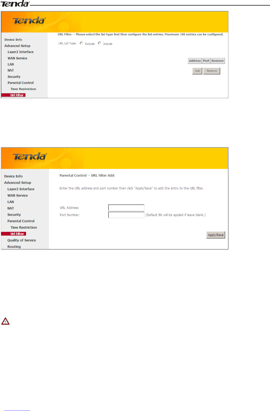
URL Filter
Here you can add URL access restriction to specific LAN PCs.
Wireless Modem Router User Guide
- 66 -
Select the URL List Type (Exclude or Include) first and then click Add to enter the screen below for configuring the list
entries. Maximum 100 entries can be configured.
URL Address: Enter the URLs that a specific LAN PC cannot access.
Port Number: Specify the port number used by the web server. The default is 80, which is the standard protocol for web
servers.
Enter the URL address and port number then click "Apply/Save" to add the entry to the URL filter.
_________________________________________________________________________________________________
Note:
If you have accessed the URL before you include it in a URL filter rule, you must reboot the router and erase it from your
PC to activate this URL filter rule. To erase the domain name from your PC, click Start -> Run, enter cmd and then type
ipconfig /flushdns.
_________________________________________________________________________________________________
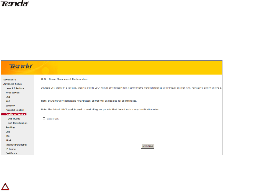
4.2.7 Quality of Service
This section explains the following:
•QoS Queue
Wireless Modem Router User Guide
- 67 -
•QoS Classification
If Enable QoS checkbox is selected, choose a default DSCP mark to automatically mark incoming traffic without
reference to a particular classifier. Click Apply/Save button to save it.
Enable QoS: Check/uncheck to enable/disable the QoS feature.
_________________________________________________________________________________________________
Note:
1. If Enable Qos checkbox is not selected, all QoS will be disabled for all interfaces.
2. The default DSCP mark is used to mark all egress packets that do not match any classification rules.
_________________________________________________________________________________________________
QoS Queue
In ATM mode, maximum 8 queues can be configured.
In PTM mode, maximum 8 queues can be configured.
For each Ethernet interface, maximum 4 queues can be configured.
For each Ethernet WAN interface, maximum 4 queues can be configured.
To add a queue, click the Add button.
To remove queues, check their remove-checkboxes, then click the Remove button.
The Enable button will scan through every queues in the table. Queues with enable-checkbox checked will be enabled.
Queues with enable-checkbox un-checked will be disabled.
The enable-checkbox also shows status of the queue after page reload.
Note that if WMM function is disabled in Wireless Page, queues related to wireless will not take effects.
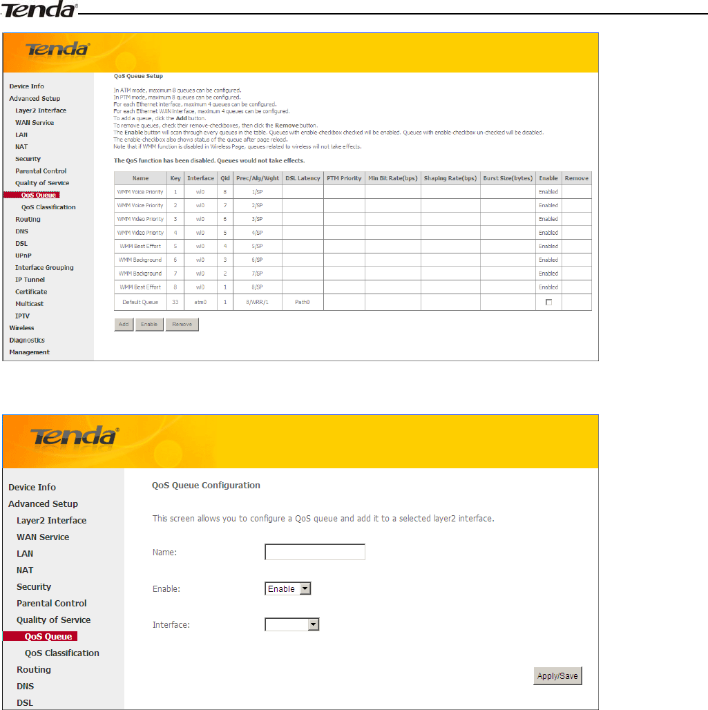
Wireless Modem Router User Guide
- 68 -
To add a queue, click the Add button to enter the following screen.
Here you can configure a QoS queue and add it to a selected layer2 interface.
QoS Classification
To add a rule, click the Add button.
To remove rules, check their remove-checkboxes, then click the Remove button.
The Enable button will scan through every rules in the table. Rules with enable-checkbox checked will be enabled.
Rules with enable-checkbox un-checked will be disabled.
The enable-checkbox also shows status of the rule after page reload.
If you disable WMM function in Wireless Page, classification related to wireless will not take effects.
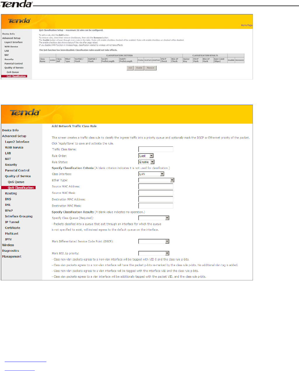
Wireless Modem Router User Guide
- 69 -
To add a rule, click the Add button to enter the following screen.
Here you can create a traffic class rule to classify the ingress traffic into a priority queue and optionally mark the DSCP
or Ethernet priority of the packet.
Click Apply/Save to save and activate the rule.
4.2.8 Routing
This section explains the following:
•Default Gateway
•Static Route
Default Gateway
Default gateway interface list can have multiple WAN interfaces served as system default gateways but only one will be
used according to the priority with the first being the highest and the last one the lowest priority if the WAN interface is
connected. Priority order can be changed by removing all and adding them back in again.
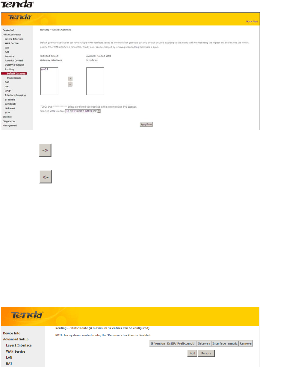
Wireless Modem Router User Guide
- 70 -
Selected Default Gateway Interfaces: Displays the selected dfault gteway iterfaces. Select a WAN interface and
click the button to move it to the Available Routed WAN Interfaces box.
Available Routed WAN Interfaces: Displays the available routed WAN interfaces. Select a WAN interface and
click the button to add it to the Selected Default Gateway Interfaces box.
Apply/Save: Click to save and activate your settings.
Static Route
Static routes provide additional routing information to your router. Typically, you do not need to add static routes.
However, when there are several routers in the network, you may want to set up static routing. Static routing determines
the path of the data in your network. You can use this feature to allow users on different IP domains to access the Internet
via this device. It is not recommended to use this setting unless you are familiar with static routing. In most cases,
dynamic routing is recommended, because this feature allows the router to detect the physical changes of the network
layout automatically. If you want to use static routing, make sure the router’s DHCP function is disabled.
Click Add to enter the following screen:
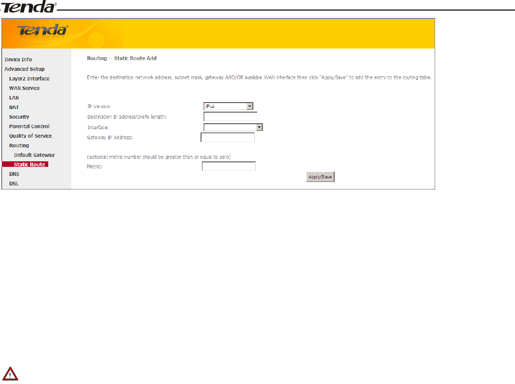
Wireless Modem Router User Guide
- 71 -
IP Version: Select either IPv4 or IPv6.
Destination IP address/prefix length: Enter the destination IP address and prefix length of the final destination.
Interface: Select an interface from the drop-down list.
Gateway IP address: Enter the gateway IP address, which must be a router on the same LAN segment as the
router.
Metric: Enter a number in the Metric field. This stands for the number of routers between your network and the
destination.
Apply /Save: Click to apply and save your settings.
_________________________________________________________________________________________________
Note:
1. Destination IP address cannot be on the same IP segment as WAN or LAN segment as the router.
2. Only configure additional static routes for unusual cases such as multiple routers or multiple IP subnets located on
your network. Wrong static routes may lead to network failure.
3. For system created route, the 'Remove' checkbox is disabled.
_________________________________________________________________________________________________
4.2.9 DNS
DNS Server (Static DNS)
The DNS server translates domain names to numeric IP addresses. It is used to look up site addresses based on their
names.
Select DNS Server Interface from available WAN interfaces OR enter static DNS server IP addresses for the system.
Here you can configure the WAN DNS address:
For IPv4:
-Click the Select DNS Server Interface from available WAN interfaces option
-OR select the Use the following Static DNS IP address option and enter static DNS server IP addresses for the system
And then click Apply/Save.
For IPv6:
-Select Obtain IPv6 DNS info from a WAN interface and Select a configured WAN interface for the IPv6 DNS server
information.
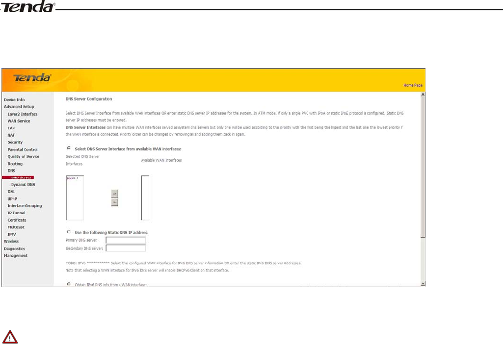
Wireless Modem Router User Guide
- 72 -
-Select Use the following Static IPv6 DNS address and enter the static IPv6 DNS server Addresses.
And then click Apply/Save.
_________________________________________________________________________________________________
Note:
1.DNS Server Interfaces can have multiple WAN interfaces served as system dns servers but only one will be used
according to the priority with the first being the higest and the last one the lowest priority if the WAN interface is
connected. Priority order can be changed by removing all and adding them back in again.
2. In ATM mode, if only a single PVC with IPoA or static IPoE protocol is configured, Static DNS server IP addresses
must be entered.
3. If you cannot locate the static DNS server IP information, ask your ISP to provide it.
4. The default settings are recommended if you are unsure about the DNS server addresses. If a wrong DNS server
address is configured, webpages may not be open.
_________________________________________________________________________________________________
Dynamic DNS (DDNS)
If your Internet service provider (ISP) gave you a static (fixed) public IP address, you can register a domain name and
have that name associated with your IP address by public Domain Name Servers (DNS). However, if your ISP gave you
a dynamic (changing) public IP address, you cannot predict what your IP address will be, and the address can change
frequently. In this case, you can use a commercial Dynamic DNS service. It lets you register your domain to their IP
address and forwards traffic directed at your domain to your frequently changing IP address.If your ISP assigns a private
WAN IP address (such as 192.168.x.x or 10.x.x.x), the Dynamic DNS service does not work because private addresses
are not routed on the Internet.
Click Advanced Setup -> DNS -> Dynamic DNS to enter the Dynamic DNS screen.
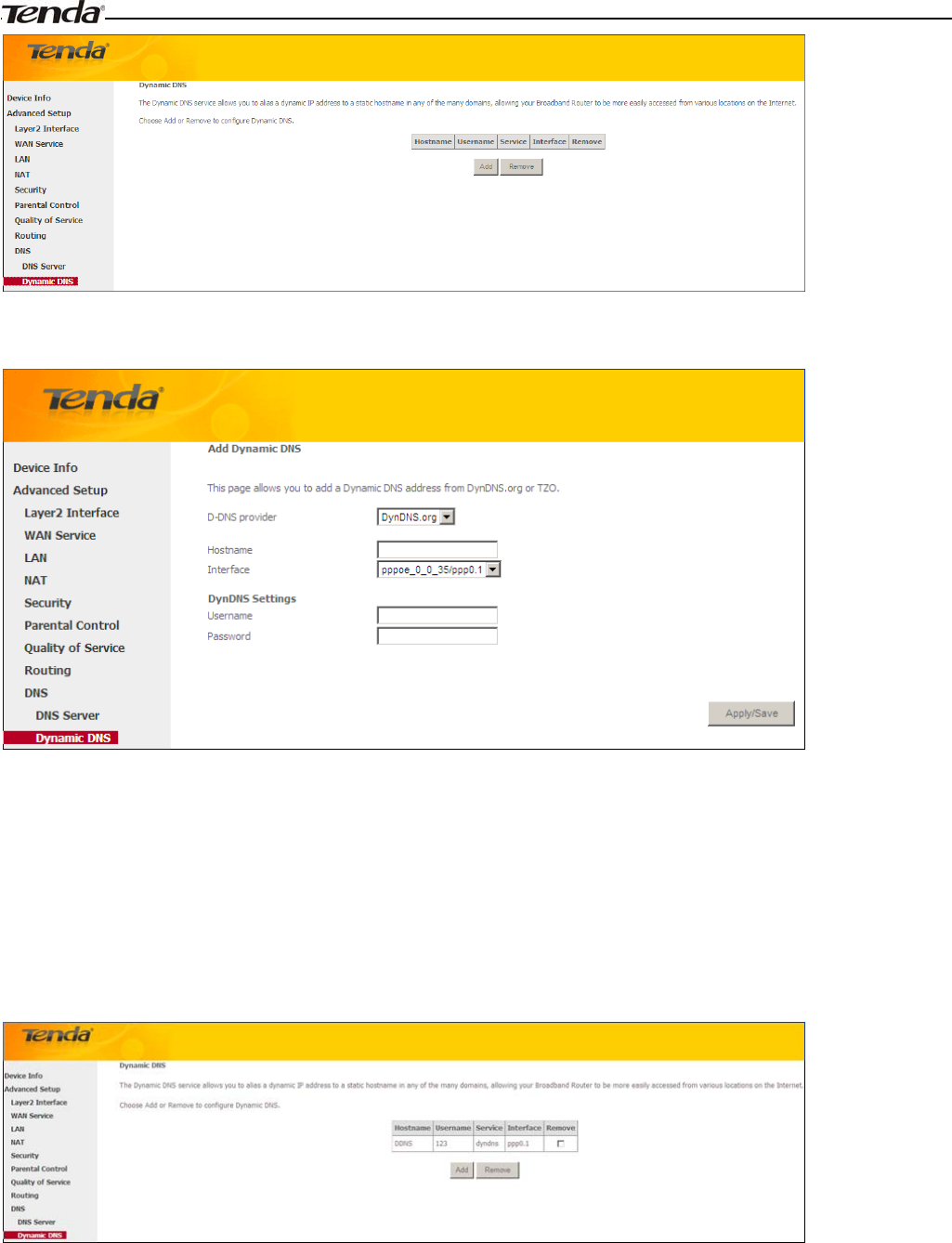
Wireless Modem Router User Guide
- 73 -
Click the Add button to configure the DDNS settings.
D-DNS Provider: Select your DDNS service provider from the drop-down menu.
Hostname: Enter the DDNS domain name registered with your DDNS service provider.
Interface: Specify a WAN connection interface.
User Name: Enter the DDNS user name registered with your DDNS service provider.
Password: Enter the DDNS Password registered with your DDNS service provider.
Click Apply/Save to save your settings.
4.2.10 DSL
This screen provides multiple ASDL modulation modes to meet diversified environments. You can also select phone line
pair and Capability.
DSL parameter configurations must be supported by ISP to take effect. Actual parameters (see Statistics-xDSL) resulted
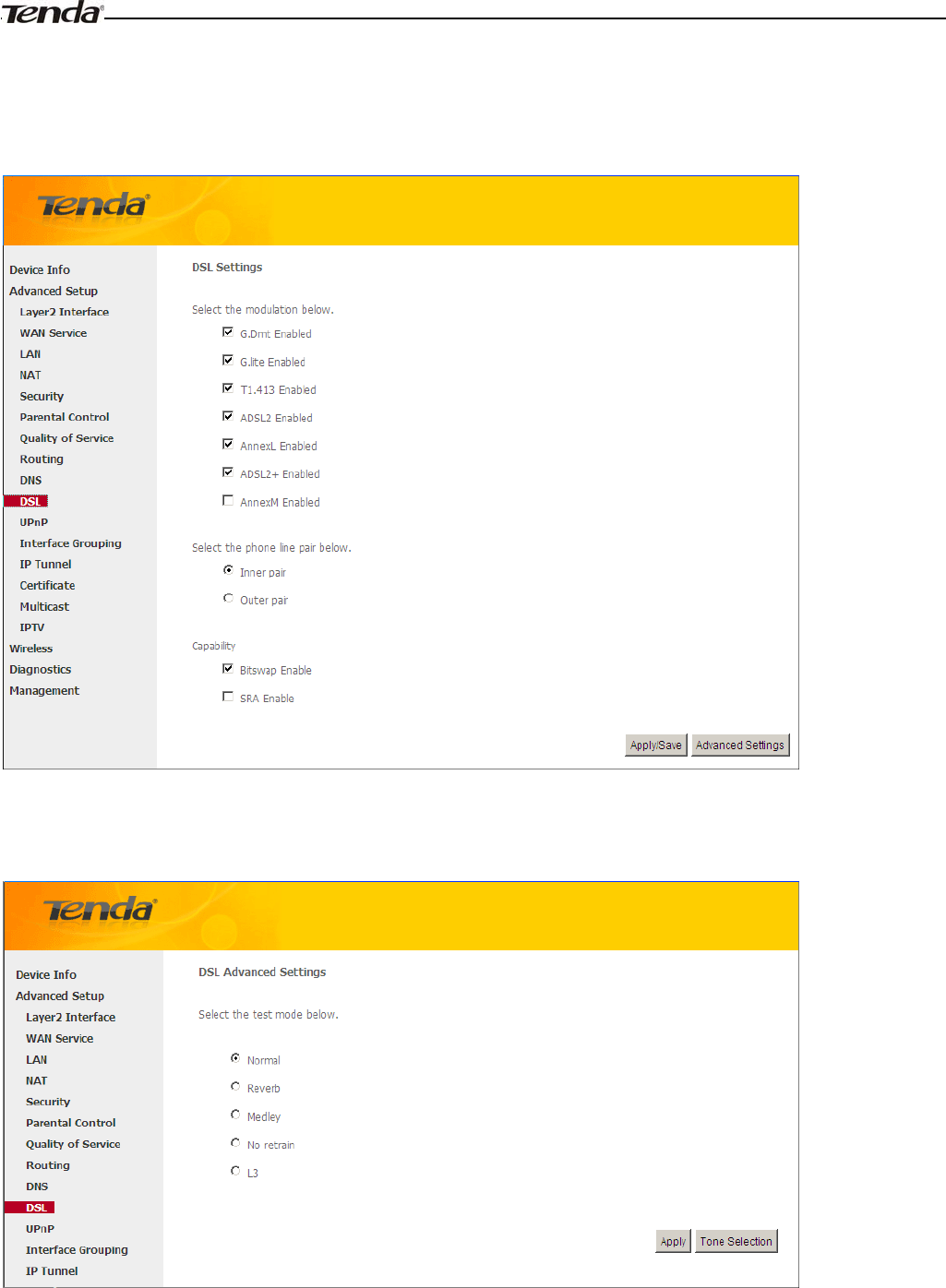
Wireless Modem Router User Guide
- 74 -
from the negotiation between your router and ISP. Wrong configurations may fail your Internet access.
The best DSL configurations are the factory defaults. Only change them if you are instructed by your ISP or our
technical staff when your router fails to negotiate with ISP in DSL (ATM) mode. Usually, this failure can be identified
and confirmed if the ADSL LED on the device keeps displaying a slow or quick blinking light.
Check the checkbox next to a modulation to enable it and then click Apply/Save.
Advanced Settings: Click to enter the Advanced Settings screen as below.
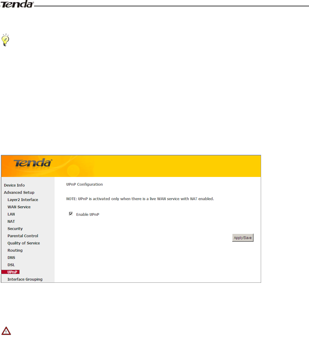
Wireless Modem Router User Guide
- 75 -
Here you can select the test mode and tone.
_________________________________________________________________________________________________
Tip:
If you are unsure about the ADSL parameters, please apply the factory default settings.Wrong configurations may fail
your Internet access.
_________________________________________________________________________________________________
4.2.11 UPnP
UPnP (Universal Plug and Play) allows Windows based systems to configure the device for various Internet applications
automatically. UPnP devices can automatically discover the services from other registered UPnP devices on the network.
If you use applications such as multiplayer gaming, peer-to-peer connections, or real-time communications, such as
instant messaging or remote assistance (a feature in Windows XP), you should enable UPnP.
Enable UPnP: Check/uncheck to enable/disable the UPnP feature.
_________________________________________________________________________________________________
Note:
UPnP is activated only when there is a live WAN service with NAT enabled.
_________________________________________________________________________________________________
4.1.12 Interface Grouping
Interface Grouping supports multiple ports to PVC and bridging groups. Each group will perform as an independent
network. To support this feature, you must create mapping groups with appropriate LAN and WAN interfaces using the
Add button. The Remove button will remove the grouping and add the ungrouped interfaces to the Default group. Only
the default group has IP interface.
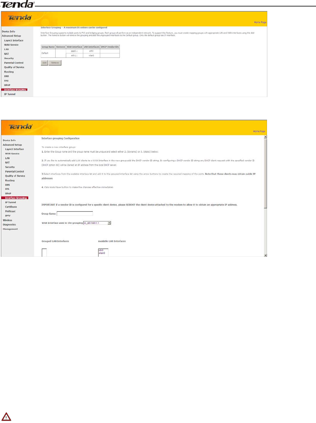
Wireless Modem Router User Guide
- 76 -
Click Add to enter the screen below:
Group Name: The name of a configured rule.
WAN Interface used in the grouping: WAN connection to which the interface grouping rules apply.
Available LAN Interfaces: LAN interfaces that can be used for interface grouping.
Grouped LAN Interfaces: LAN interfaces that use specified WAN interface.
To create a new interface group:
1. Enter the Group name and the group name must be unique and select either 2. (dynamic) or 3. (static) below:
2. If you like to automatically add LAN clients to a WAN Interface in the new group add the DHCP vendor ID string.
By configuring a DHCP vendor ID string any DHCP client request with the specified vendor ID (DHCP option 60)
will be denied an IP address from the local DHCP server.
Select interfaces from the available interface list and add it to the grouped interface list using the arrow buttons to
create the required mapping of the ports. Note that these clients may obtain public IP addresses.
3. Click Apply/Save button to make the changes effective immediately.
_________________________________________________________________________________________________
Note:
If a vendor ID is configured for a specific client device, please REBOOT the client device attached to the modem to
allow it to obtain an appropriate IP address.
_________________________________________________________________________________________________
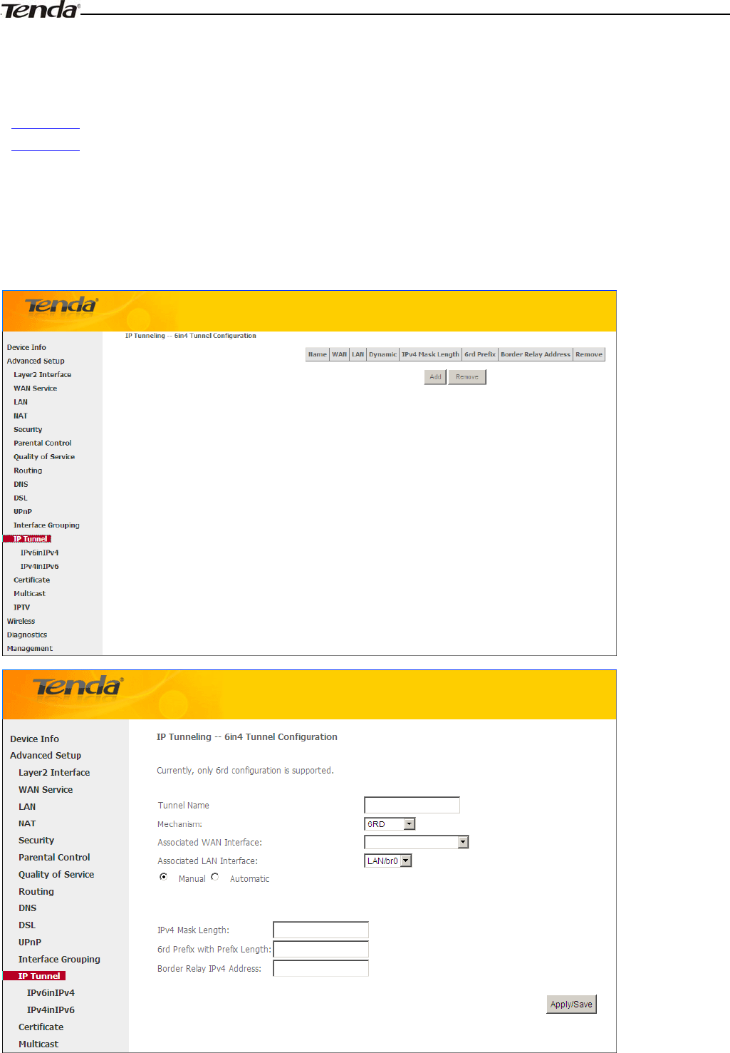
Wireless Modem Router User Guide
- 77 -
4.1.13 IP Tunnel
This section explains the following information:
•IPv6inIPv4
•IPv4inIPv6
IPv6inIPv4
Click IPv6inIPv4 and Add to enter the following screen:
¾Tunnel Name: Specify the name of the tunnel.
¾Mechanism: Currently, only DS-Lite configuration is supported..
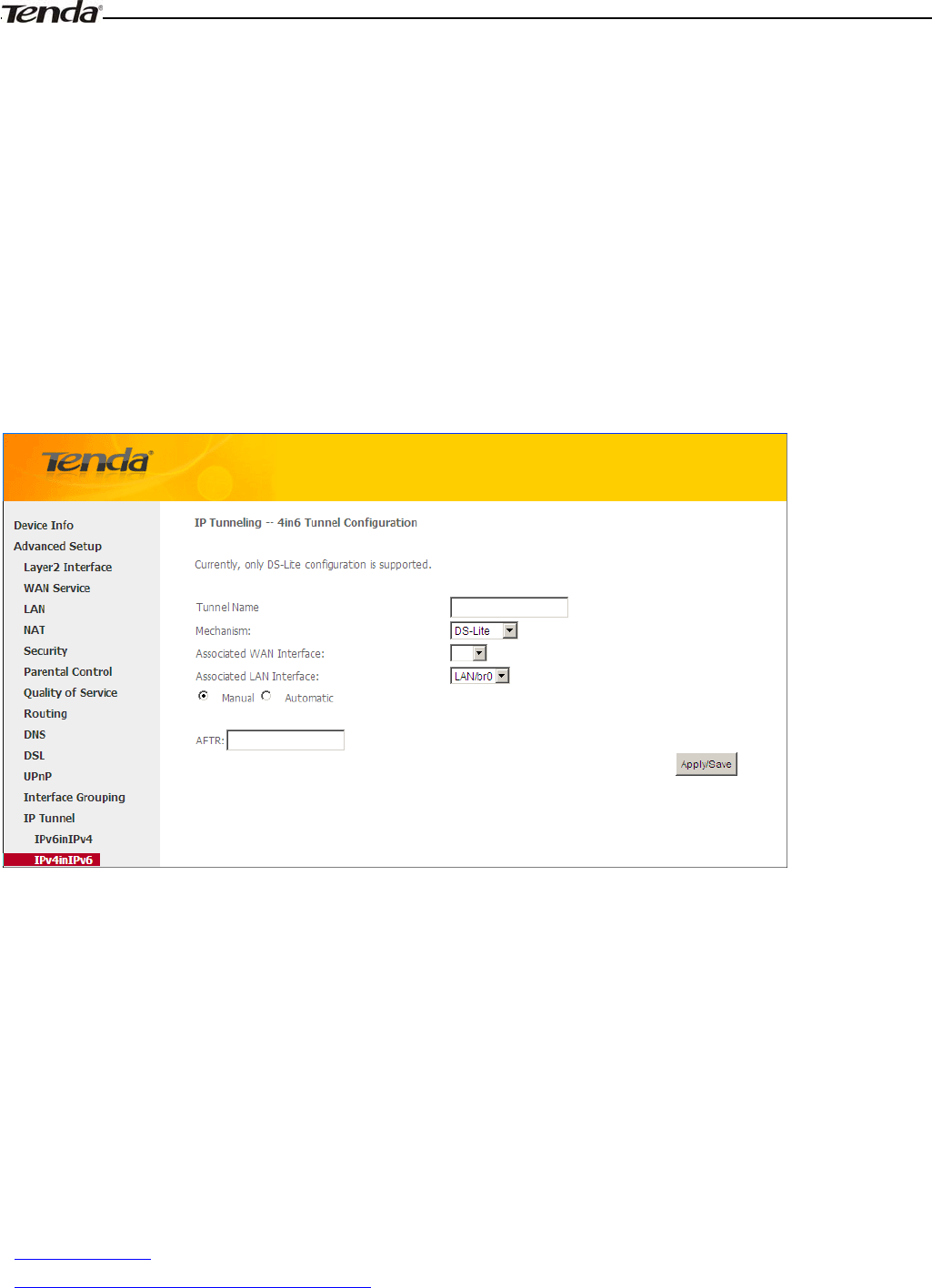
Wireless Modem Router User Guide
- 78 -
¾Associated WAN Interface: Specify the WAN iterface of the tunnel.
¾Associated LAN Interface: Specify the LAN iterface of the tunnel.
¾Manual: If you select Manual, configure the following settings also:
IPv4 Mask Length: Specify the IPv4 Mask Length.
6rd Prefix with Prefix Length: Specify the 6rd Prefix with Prefix Length.
Border Relay IPv4 Address: Specify the Border Relay IPv4 Address.
¾Automatic: If Automatic is selected, no configurations are required.
¾Apply/Save: Click to apply and save your settings.
IPv4inIPv6
Click IPv4inIPv6 and Add to enter the following screen:
¾Tunnel Name: Specify the name of the tunnel.
¾Mechanism: Currently, only 6rd configuration is supported.
¾Associated WAN Interface: Specify the WAN iterface of the tunnel.
¾Associated LAN Interface: Specify the LAN iterface of the tunnel.
¾Manual: If you select Manual, enter the AFTR information also:
¾Automatic: If Automatic is selected, no configurations are required.
¾Apply/Save: Click to apply and save your settings.
4.1.14 Certificate
This section explains the following information:
•Local Certificates
•Trusted CA (Certificate Authority) Certificates
Local Certificates
Here you can Add, View or Remove certificates. Local certificates are used by peers to verify your identity. Maximum 4
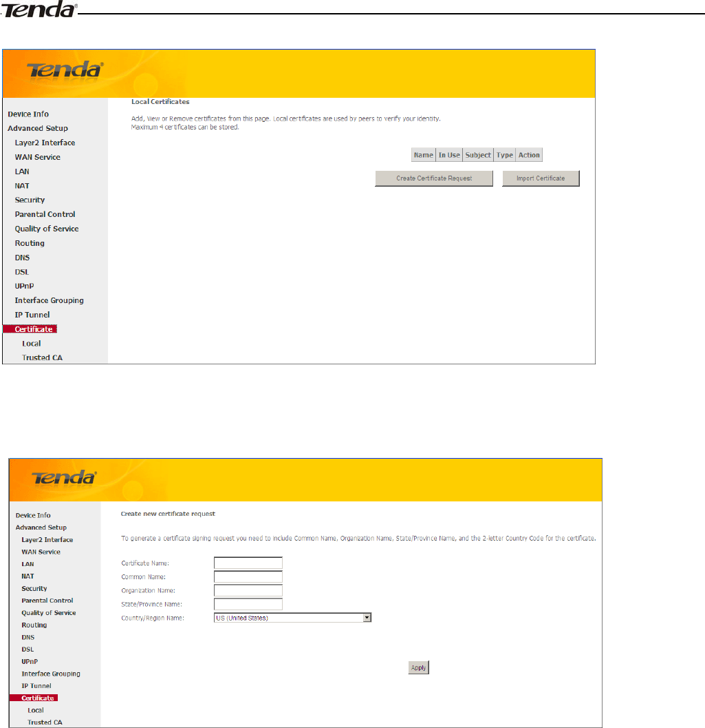
Wireless Modem Router User Guide
- 79 -
certificates can be stored.
To generate generate a certificate signing request:
1. Click the Create Certificate Request button to enter the page below.
2. Specify the Common Name, Organization Name and State/Province Name
3. Enter the 2-letter Country Code for the certificate.
4. Click Apply to apply your settings.
To Import certificate
˖
1. Click the Import Certificate button on the local certificates page to enter the page below.
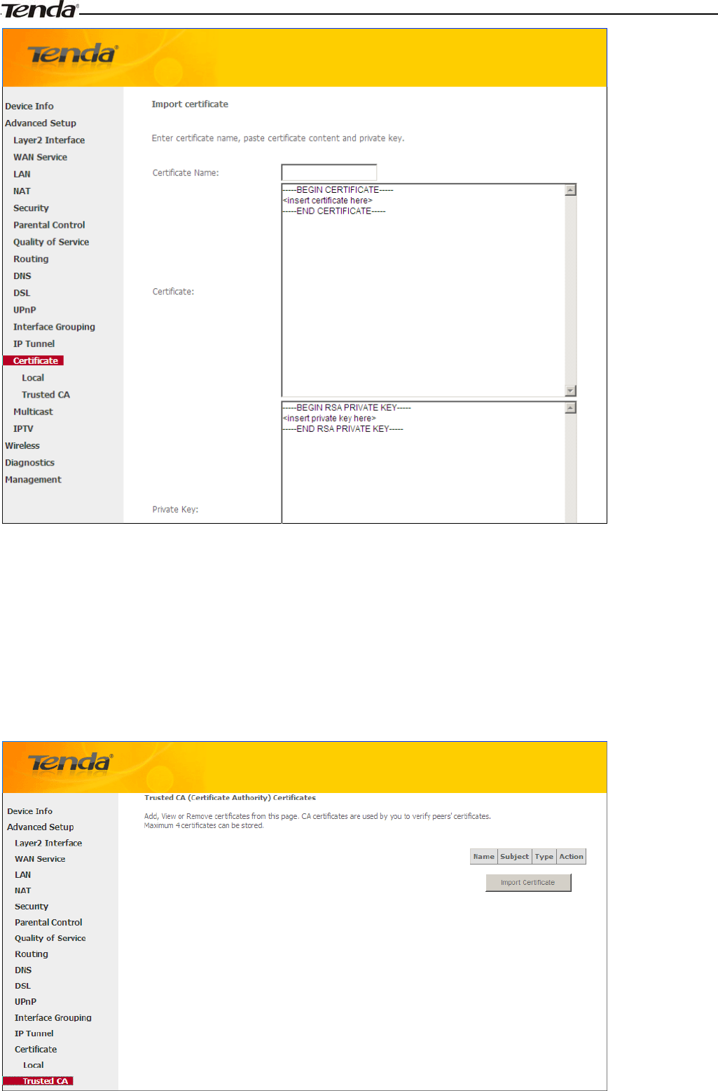
Wireless Modem Router User Guide
- 80 -
2. Enter the certificate name.
3. Paste the certificate content and private key.
4. Click Apply to apply your settings.
Trusted CA (Certificate Authority) Certificates
Here you can Add, View or Remove CA certificates. CA certificates are used by you to verify peers' certificates.
Maximum 4 certificates can be stored.
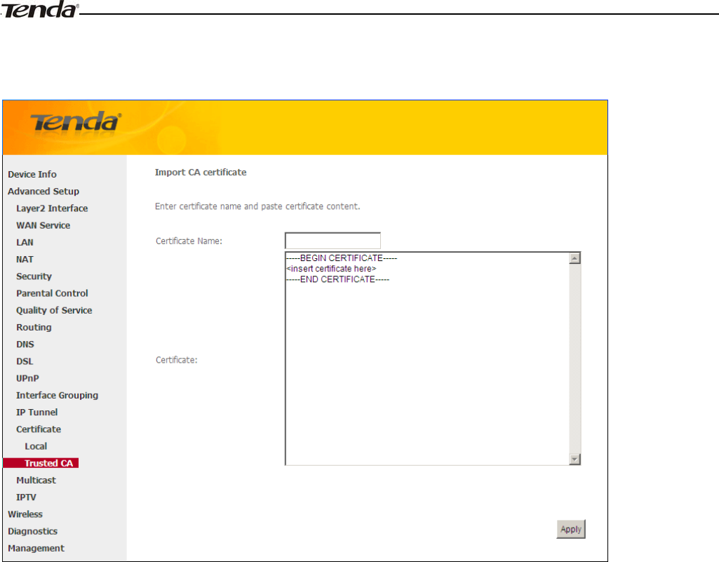
Wireless Modem Router User Guide
- 81 -
To Import certificate
˖
1. Click the Import Certificate button to enter the page below.
2. Enter the certificate name.
3. Paste the certificate content.
4. Click Apply to apply your settings.
4.1.15 Multicast
Here you can configure the multicast feature.
To configure IGMP for IPv4
1. Check the LAN to LAN (Intra LAN) Multicast Enable box.
2. Check the Mebership Join Immediate (IPTV) box. This is only required for IPTV.
3. Keep other options unchanged from factory defaults if you are not an advanced user. This is strongly recommended.
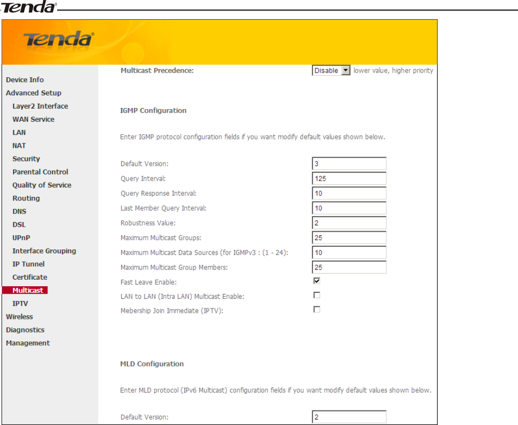
Wireless Modem Router User Guide
- 82 -
To configure IGMP for IPv6
1. Check the LAN to LAN (Intra LAN) Multicast Enable box.
2. Keep other options unchanged from factory defaults if you are not an advanced user. This is strongly recommended.
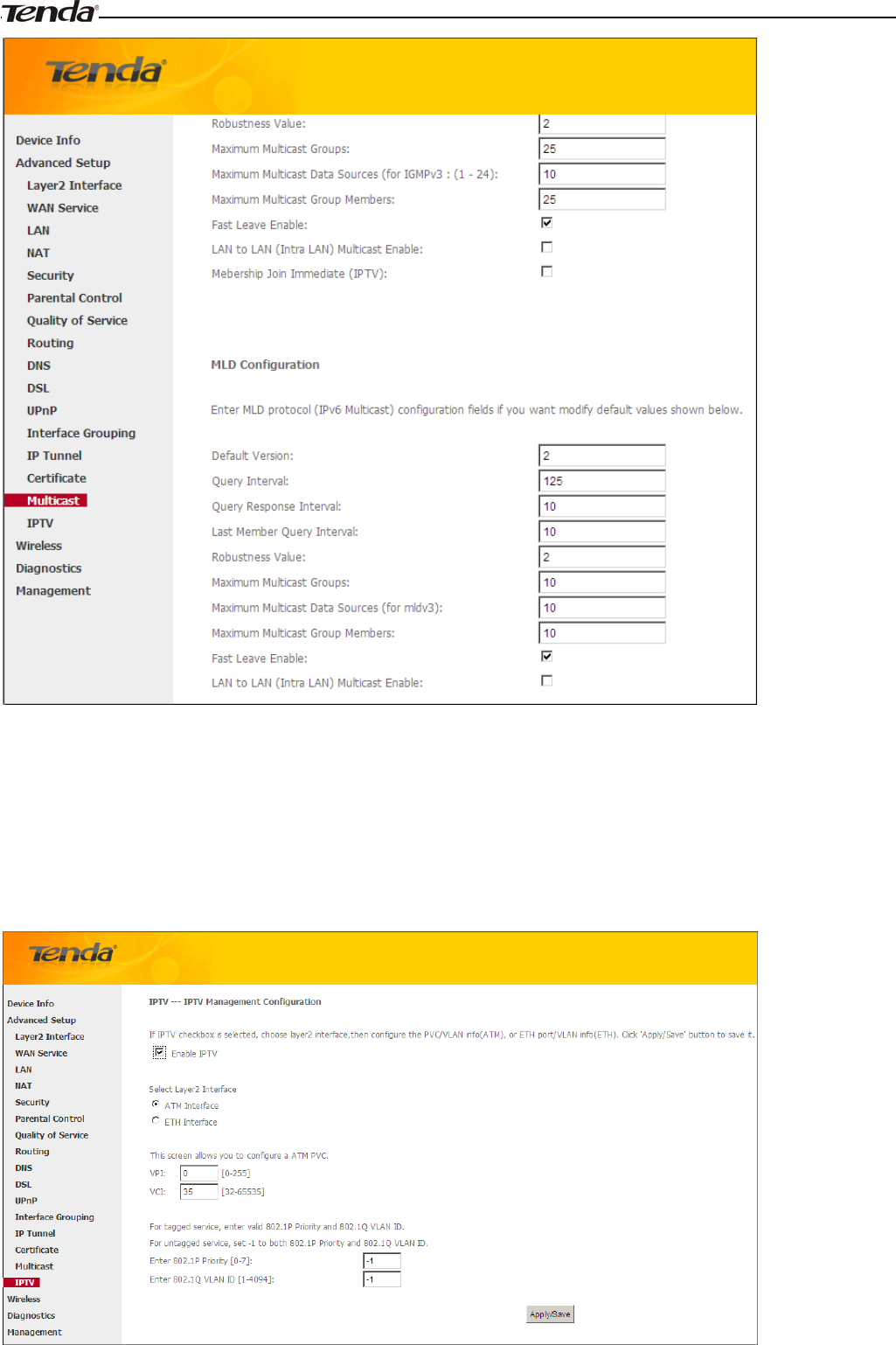
Wireless Modem Router User Guide
- 83 -
4.1.16 IPTV
If you check the Enable IPTV checkbox, you must choose a layer2 interface, and then configure the PVC/VLAN info
(ATM), or ETH port/VLAN info (ETH). Click Apply/Save button to save it.
Enable IPTV: Check/uncheck to enable/disable the IPTV service.
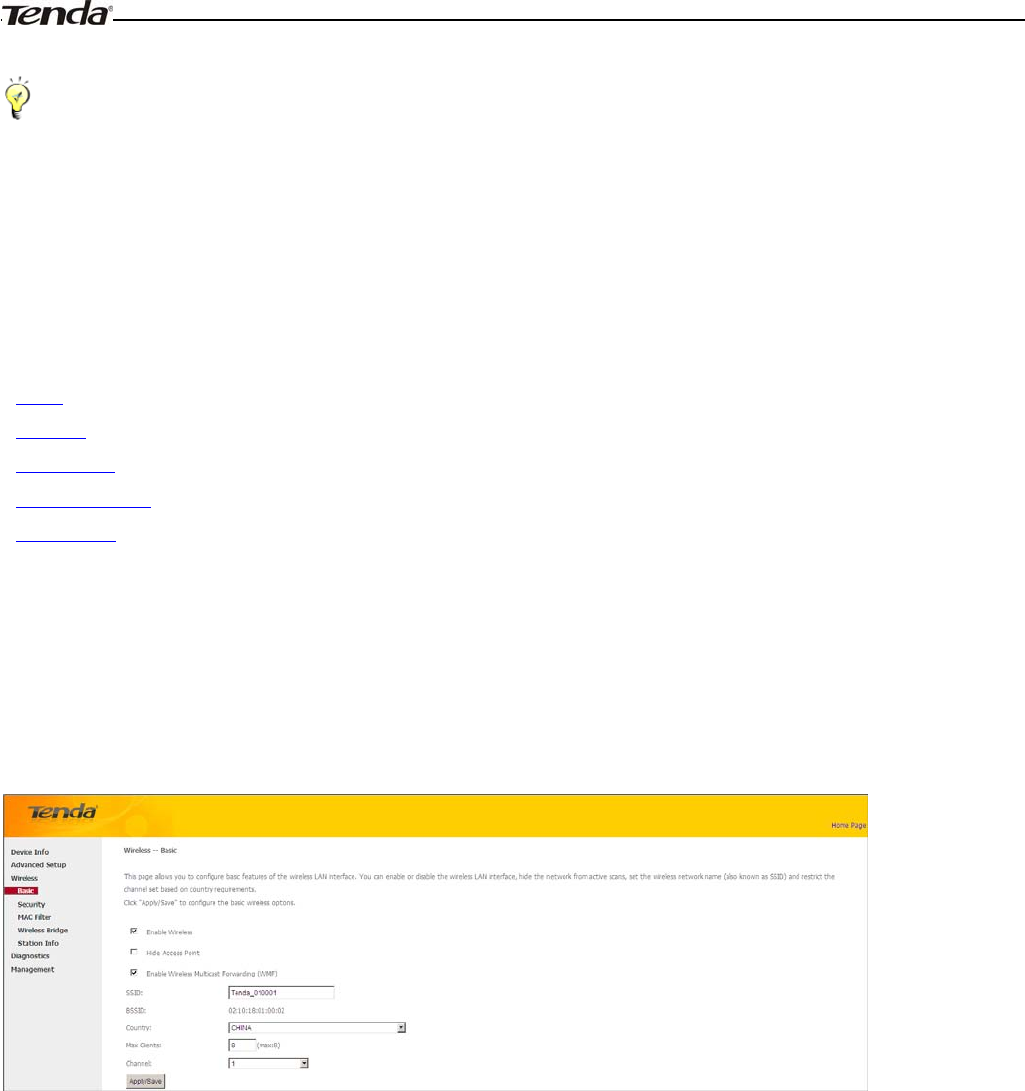
Wireless Modem Router User Guide
- 84 -
_________________________________________________________________________________________________
Tip:
For tagged service, enter valid 802.1P Priority and 802.1Q VLAN ID.
For untagged service, set -1 to both 802.1P Priority and 802.1Q VLAN ID.
_________________________________________________________________________________________________
4.3 Wireless
This section explains the following information:
•Basic
•Security
•MAC Filter
•Wireless Bridge
•Station Info
4.3.1 Basic
This page allows you to configure basic features of the wireless LAN interface. You can enable or disable the wireless
LAN interface, hide the network from active scans, set the wireless network name (also known as SSID) and restrict the
channel set based on country requirements.
Click Apply/Save to configure the basic wireless options.
Enable Wireless: check/uncheck to enable/disable the wireless feature.
SSID: This is thepublic name of your wireless network.
Hide SSID (Hide Access Point): This option allows you to have your network names (SSID) publicly broadcast or
if you choose to enable it, the SSID will be hidden.
BSSID
˖
Display the BSSID.
Country: Select your country.
Max Clients: The max wireless clients your wireless network can accept. Up to 8 clients can join your wireless network
at a time. The default setting is 8.
Channel: Select a channel or select Auto to let system automatically select one for your wireless network to operate on
if you are unsure. The best selection is a channel that is the least used by neighboring networks.
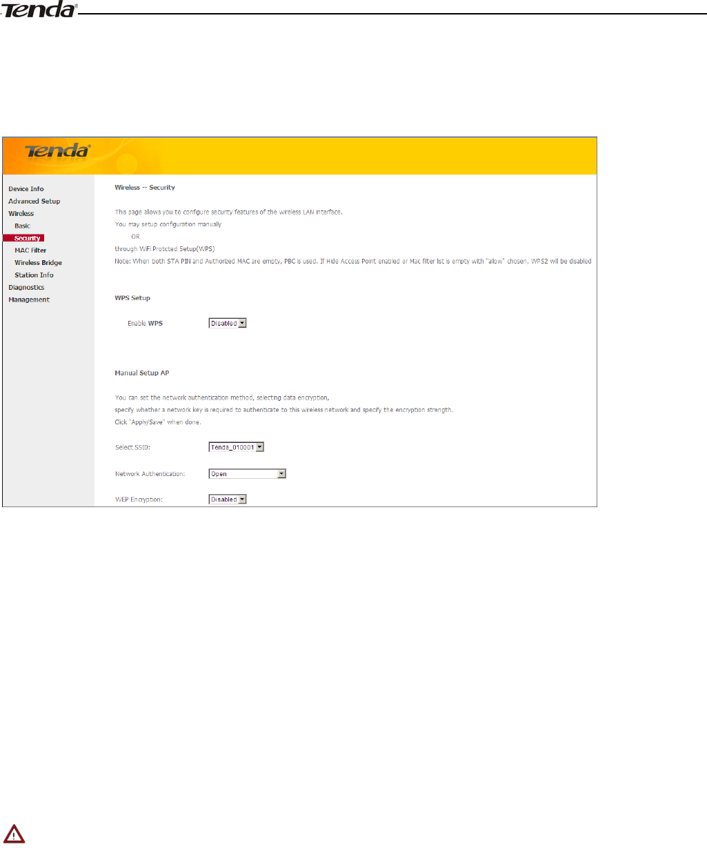
Wireless Modem Router User Guide
- 85 -
4.3.2 Security
This page allows you to configure security features of the wireless LAN interface. You may setup configuration
manually OR through WiFi Protcted Setup (WPS).
WPS Setup
Wi-Fi Protected Setup makes it easy for home users who know little of wireless security to establish a home network, as
well as to add new devices to an existing network without entering long passphrases or configuring complicated settings.
Simply enter a PIN code on the device web interface or press hardware WPS button (on the back panel of the device) and
a secure wireless connection is established.
WPS Button: Press the hardware WPS button on the device for 1 second and the WPS LED will keep blinking for about
2 minutes. Within the 2 minutes, press the WPS button on your wireless computer or other device. When the WPS
displays a solid light, the device has joined your wireless network.
PIN: To use this option, you must know the PIN code from the wireless client and enter it in the corresponding field on
your device while using the same PIN code on client side for such connection.
Enable WPS: Check/uncheck to enable/disable the WPS function. It is enabled by default.
_________________________________________________________________________________________________
Note:
1. To use the WPS security, the wireless client must be also WPS-capable.
2. When both STA PIN and Authorized MAC are empty, PBC is used. If Hide Access Point enabled or Mac filter list is
empty with "allow" chosen, WPS2 will be disabled.
_________________________________________________________________________________________________
Manual Setup AP
You can set the network authentication method, selecting data encryption, specify whether a network key is required to
authenticate to this wireless network and specify the encryption strength.
Click "Apply/Save" when done.
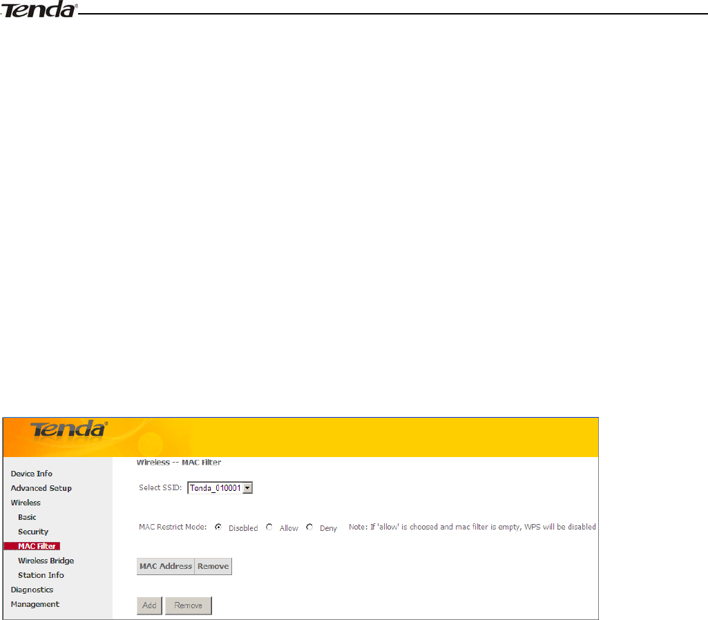
Wireless Modem Router User Guide
- 86 -
Network Authentication: Select Open, Shared, WPA-PSK, WPA2-PSK or Mixed WPA/ WPA2-PSK from the
drop-down list to encrypt your wireless network.
Depending on the type of network authentication you select, you will be prompted to enter corresponding settings.
WEP Encryption: Select Enabled or Disabled.
Encryption Strength: Select 128-bit or 64-bit.
Current Network Key: Select a network key to be active.
Network Key 1/2/3/4: Enter 13 ASCII characters or 26 hexadecimal digits for 128-bit encryption keys; enter 5 ASCII
characters or 10 hexadecimal digits for 64-bit encryption keys.
WPA/WAPI passphrase: Enter a WPA/WAPI network key.
WPA Group Rekey Interval: Specify a key update interval.
WPA/WAPI Encryption: Select AES or TKIP+AES.
4.3.3 MAC Filter
The MAC-based Wireless Access Control feature can be used to allow or disallow clients to connect to your wireless
network.
Allow: Only allow PCs at specified MAC addresses (in the list) to connect to your wireless network.
Deny: Block only PCs at specified MAC addresses from connecting to your wireless network.
Disable: Disable this feature.
Add: Click to add a MAC address.
To delete an existing MAC address, first check the Remove box next to the MAC address in list and then click the
Remove button.
Example 1: To allow only the PC at the MAC address of 00:1A:3D:9C:BB:23 to connect to your wireless network, do as
follows:
1. Select Allow.
2. Click the Add button.
3. Enter 00:1A:3D:9C:BB:23 in the MAC address box as shown in the figure below:
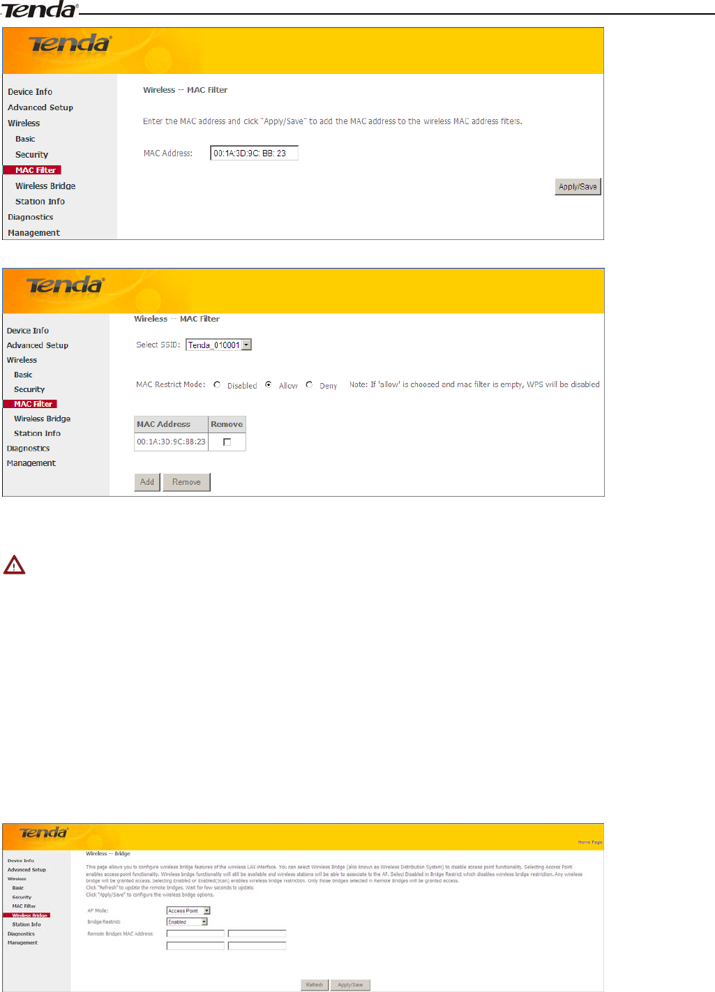
Wireless Modem Router User Guide
-87-
4. Click Apply/Save.
_________________________________________________________________________________________________
Note:
If “allow” is choosed and mac filter is empty, WPS will be disabled.
_________________________________________________________________________________________________
4.3.4 Wireless Bridge
This page allows you to configure wireless bridge (also known as Wireless Distribution System) features of the wireless
LAN interface.
Wireless distribution system (WDS) is a system enabling the wireless interconnection of access points in an IEEE 802.11
network. It allows a wireless network to be expanded using multiple access points without the traditional requirement for
a wired backbone to link them.
AP Mode: You can select Wireless Bridge (also known as Wireless Distribution System) to disable access point
functionality. Selecting Access Point enables access point functionality. Wireless bridge functionality will still be
available and wireless stations will be able to associate to the AP.
Bridge Restrict: There are three options available: Enabled, Enabled (Scan) and Disabled. Select Disabled in Bridge
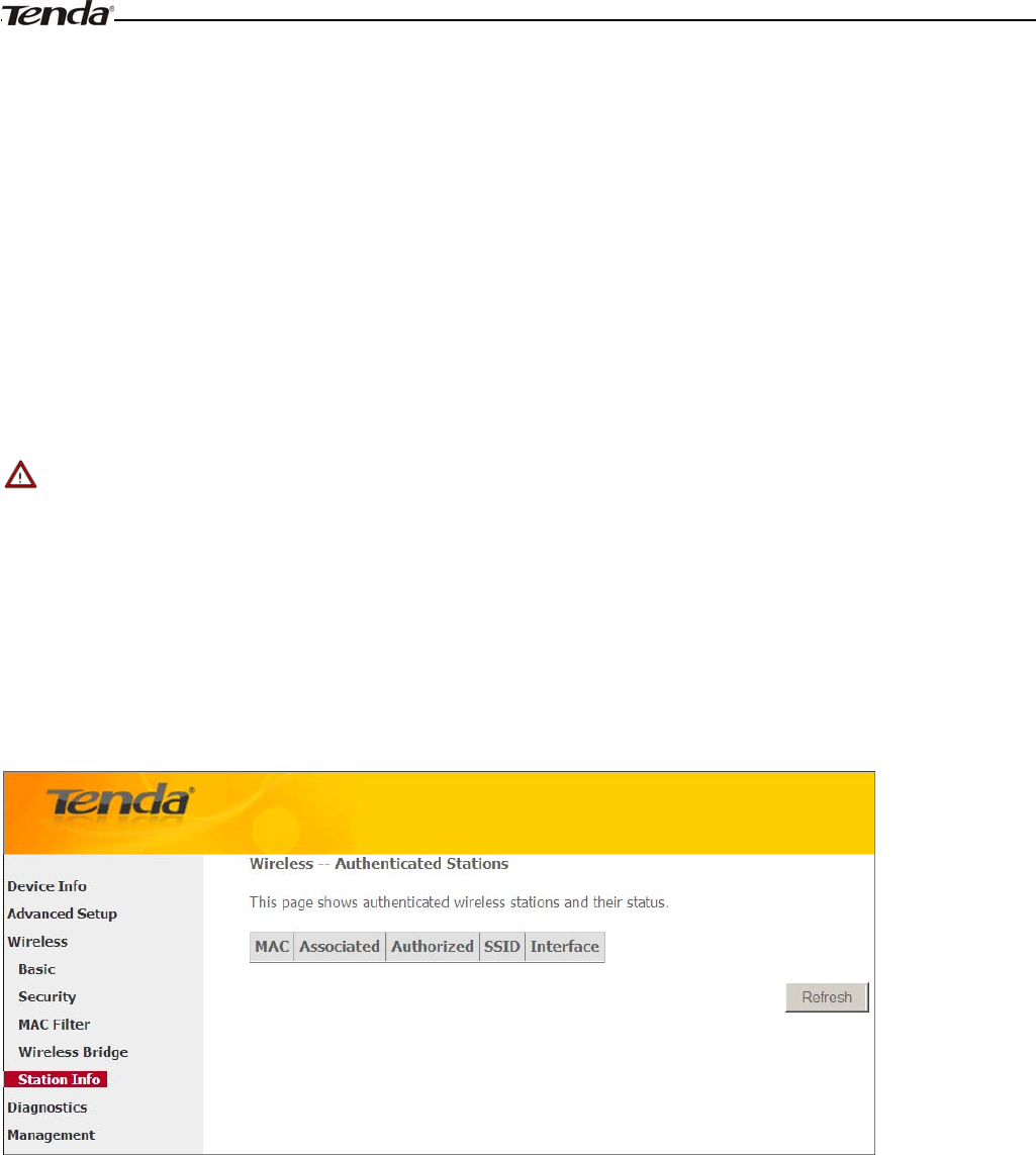
Wireless Modem Router User Guide
- 88 -
Restrict which disables wireless bridge restriction. Any wireless bridge will be granted access. Selecting Enabled or
Enabled (Scan) enables wireless bridge restriction. Only those bridges selected in Remote Bridges will be granted access.
The Enabled (Scan) enables wireless bridge restriction and automatically scans the remote bridges.
Remote Bridges MAC Address: Specify the MAC address of the remote bridge. If you select the Enabled (Scan) option
in Bridge Restrict, system automatically scans the remote bridges and you only need to select those bridges and their
MAC addresses will be added to automatically.
Refresh: Click to update the remote bridges. Wait for few seconds to update.
Apply/Save: Click to apply and save the settings.
_________________________________________________________________________________________________
Note:
The WDS feature (also known as Wireless Bridge) can only be implemented between 2 WDS-capable wireless devices.
Plus, SSID, channel, security settings and security key must be exactly the same on both such devices.
_________________________________________________________________________________________________
4.3.5 Station Info
This page shows authenticated wireless stations and their status.
4.4 Diagnostics
The modem router is capable of testing the connection to your DSL service provider, the connection to your Internet
service provider and the connection to your local network. If a test displays a fail status, click "Rerun Diagnostic Tests"
at the bottom of this page to make sure the fail status is consistent. If the test continues to fail, click "Help" and follow
the troubleshooting procedures.
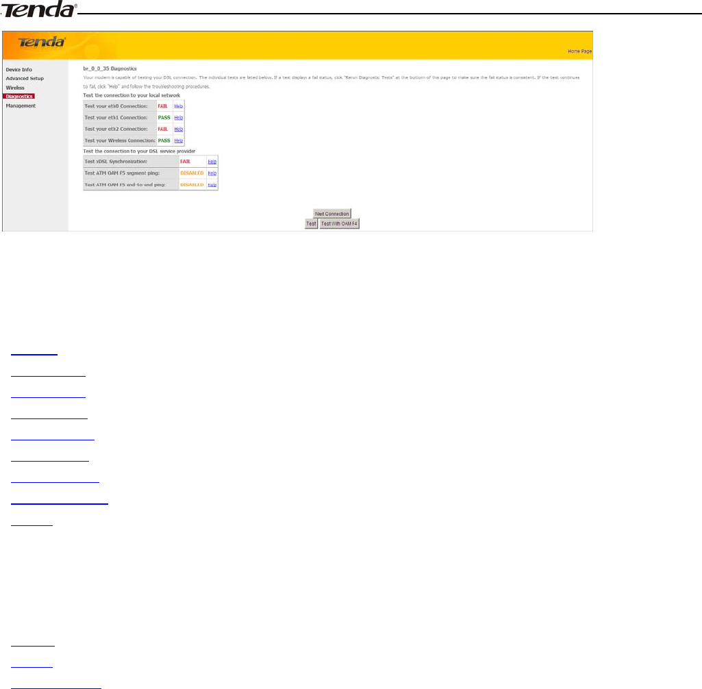
Wireless Modem Router User Guide
- 89 -
4.5 Management
This section explains the following information:
•Settings
•System Logs
•Security Log
•SNMP Agent
•TR-069 Client
•Internet Time
•Access Control
•Update Software
•Reboot
4.5.1 Settings
This section explains the following information:
•Backup
•Update
•Restore Default
Backup
Here you can save a copy of your device’s configurations to your computer. Once you have configured the device,
you can save these settings to a configuration file on your local hard drive. The configuration file can later be imported to
your device in case the device is reset to factory default settings.
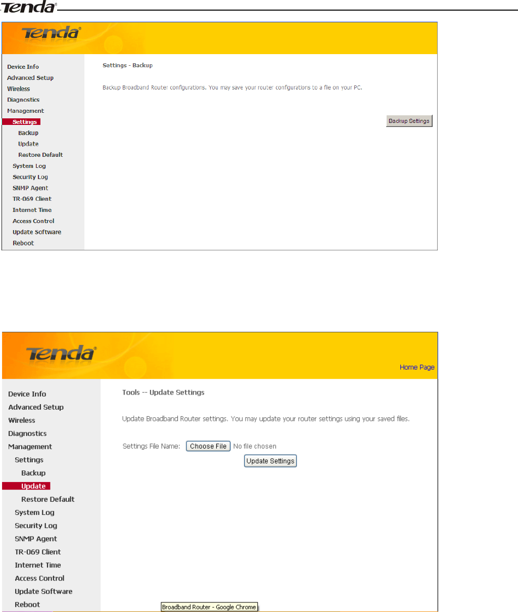
Wireless Modem Router User Guide
- 90 -
Update
Here you can restore the configuration from a file saved on your PC.
Restore Default
Under some circumstances (for example, join a different network or unfortunately forgetting the login password), you
may need to remove the existing configuration and restore the factory default settings.
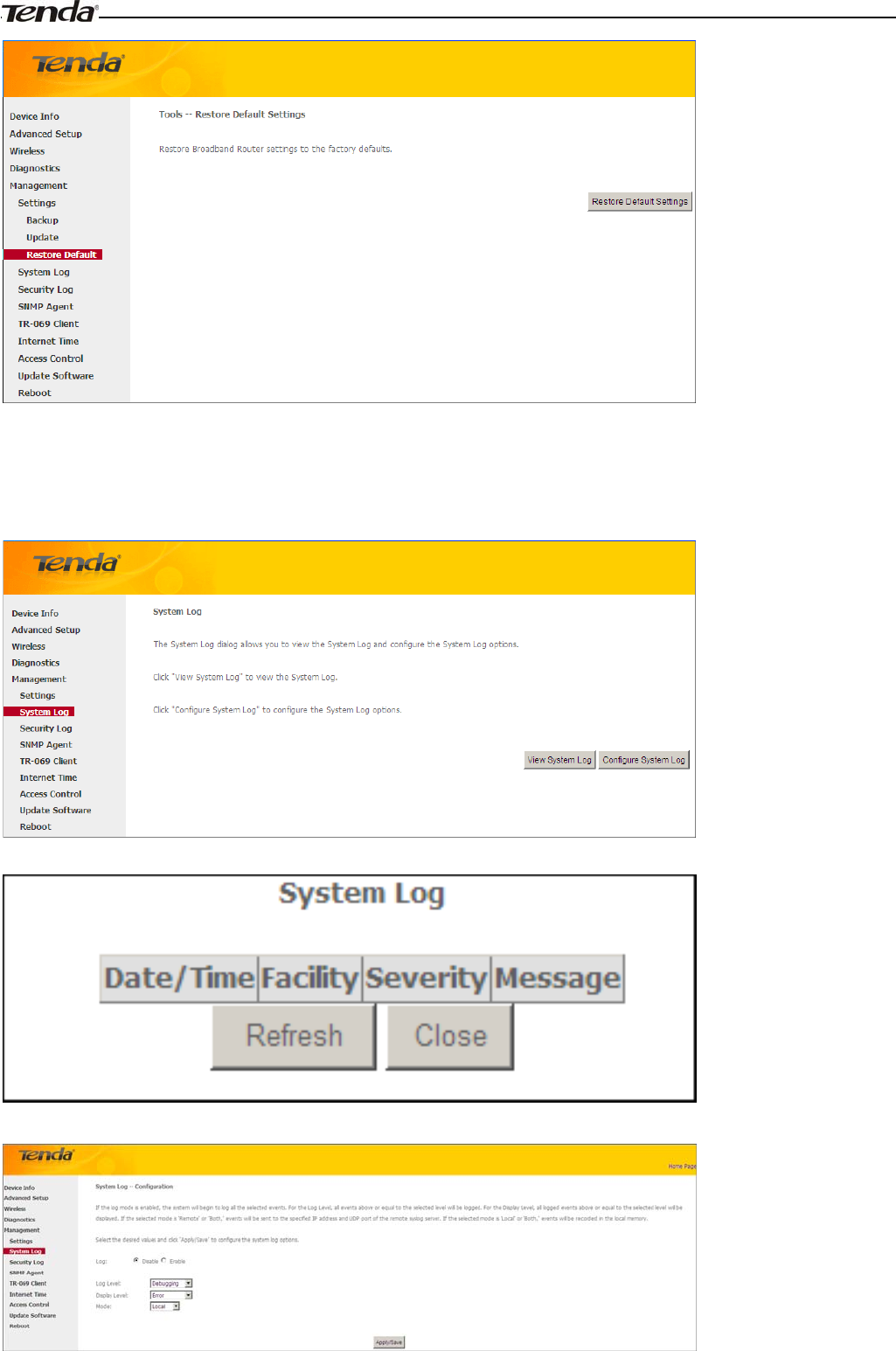
Wireless Modem Router User Guide
- 91 -
4.5.2 System Logs
The System Log dialog allows you to view the System Log and configure the System Log options.
To view the System Log, simply click View System Log.
To configure the System Log options, click Configure System Log.
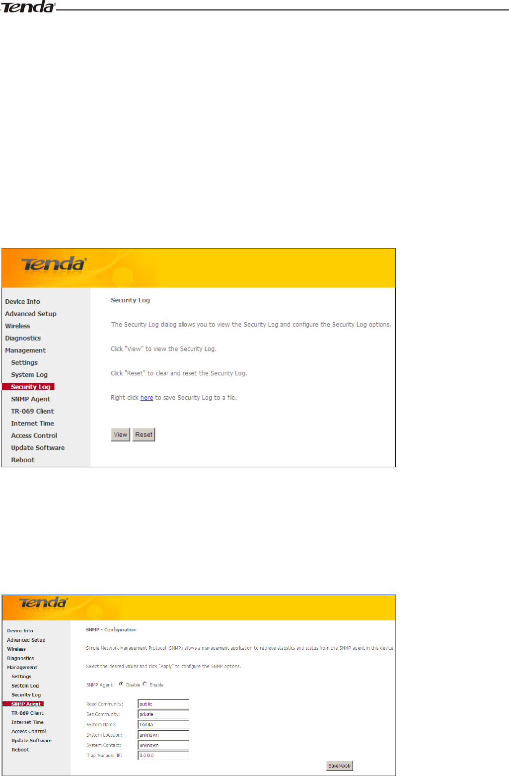
Wireless Modem Router User Guide
- 92 -
Log: If Enable is selected, the system will begin to log all the selected events.
Log Level: All events above or equal to the selected level will be logged.
Display Level: All logged events above or equal to the selected level will be displayed.
Mode: If the selected mode is 'Remote' or 'Both,' events will be sent to the specified IP address and UDP port of the
remote syslog server. If the selected mode is 'Local' or 'Both,' events will be recorded in the local memory.
Server IP Address: Specify the IP address of the remote syslog server.
Server UDP Port: Specify the UDP port of the remote syslog server.
Apply/Save: click to apply and save the system log settings.
4.5.3 Security Log
The Security Log page allows you to view the Security Log and configure the Security Log options. You can also save
Security Log to a file.
View: Click to view the Security Log.
Reset: Click to clear and reset the Security Log.
4.5.4 SNMP Agent
Simple Network Management Protocol (SNMP) allows a management application to retrieve statistics and status from
the SNMP agent in this device.
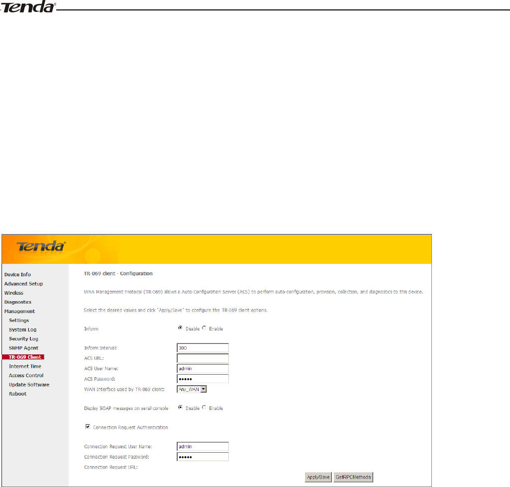
Wireless Modem Router User Guide
- 93 -
SNMP Agent
˖
Select “Enable” to activate the SNMP Agent feature or “Disable” to deactivate it.
Read Community: Specify a Read Community string. The default is public.
Set Community: Specify a Set Community string. The default is private.
System Name: Specify a descriptive system name.
System Location: Specify a system location.
System Contact: Specify a system contact.
Trap Manager IP: Specify the IP address of the Trap Manager.
4.5.5 TR-069 Client
WAN Management Protocol (TR-069) allows a Auto-Configuration Server (ACS) to perform auto-configuration,
provision, collection, and diagnostics to this device.
Click the TR-069 Client tab to enter the TR-069 Client configuration screen as seen below:
Inform˖Select Enable/Disable to enable/disable the TR-069 Client function. By default, it is disabled.
Inform Interval: Specify the inform interval.
ACS URL: Enter the ACS (Auto-Configuration Server) URL address.
ACS User Name: Enter the ACS (Auto-Configuration Server) user name.
ACS Password: Enter the ACS (Auto-Configuration Server) password.
WAN Interface used by TR-069 client: Select the WAN interface used by the TR-069 client from the drop-down list.
Display SOAP messages on serial console: If Enable is selected, SOAP messages will be displayed on serial console; if
Disable is selected, SOAP messages will not be displayed on serial console.
Connection Request Authentication: Check/uncheck to enable/disable the cnnection request authentication.
Connection Request User Name: Enter the cnnection request user name.
Connection Request Password: Enter the cnnection request password.
Connection Request URL: Specify the connection request URL.
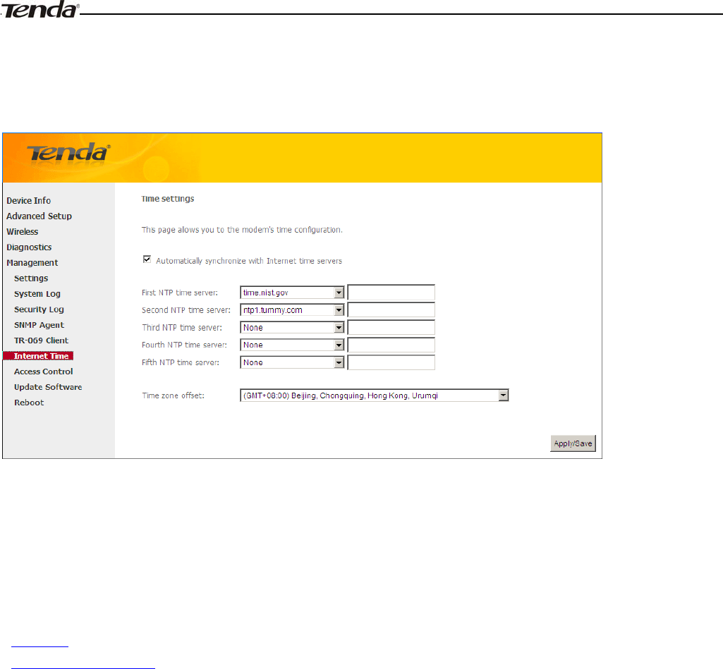
Wireless Modem Router User Guide
- 94 -
4.5.6 Internet Time
This page is used to set the router’s system time. If Automatically synchronize with Internet time servers is checked,
the system will automatically connect to NTP server to synchronize the time.
First/Second/Third/Fourth/Fifth NTP time server: Select a NTP time server from the drop-down list. If the NTP time
server you are looking for is not included in the list, select “Other” and then enter it manually in the box.
Time zone offset: Select your time zone from the drop-down list.
4.5.7 Access Control
This section explains the following information:
•Password
•AccessControl - Service
Password
Access to your broadband router is controlled through three user accounts: admin, support, and user.
The user name "admin" has unrestricted access to change and view configuration of your Broadband Router.
The user name "support" is used to allow an ISP technician to access your Broadband Router for maintenance and to run
diagnostics.
The user name "user" can access the Broadband Router, view configuration settings and statistics, as well as, update the
router's software.
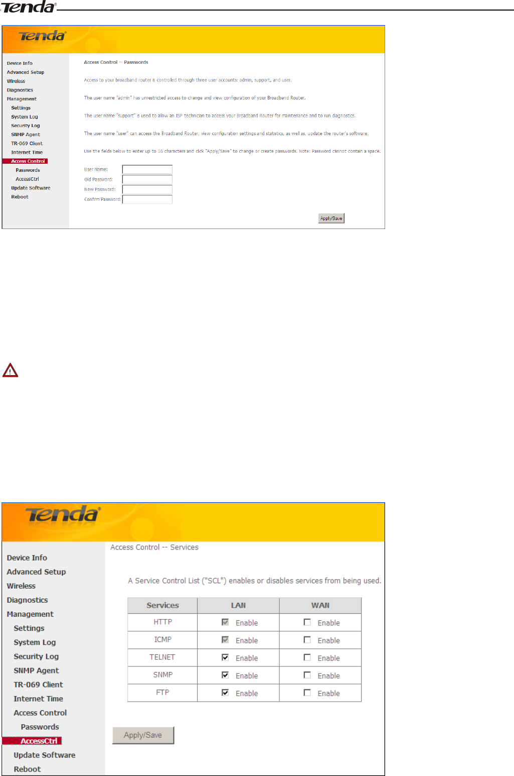
Wireless Modem Router User Guide
- 95 -
User Name: Enter the user name of up to 16 characters.
Old Password: Enter the old password of up to 16 characters.
New Password: Enter a new password of up to 16 characters.
Confirm Password: Re-enter to confirm the new password.
Apply/Save: Click to change or create passwords.
_________________________________________________________________________________________________
Note:
Password cannot contain a space.
_________________________________________________________________________________________________
AccessControl - Service
Here you can manage the device either from LAN or WAN side using HTTP, ICMP, TELNET, SNMP and FTP.
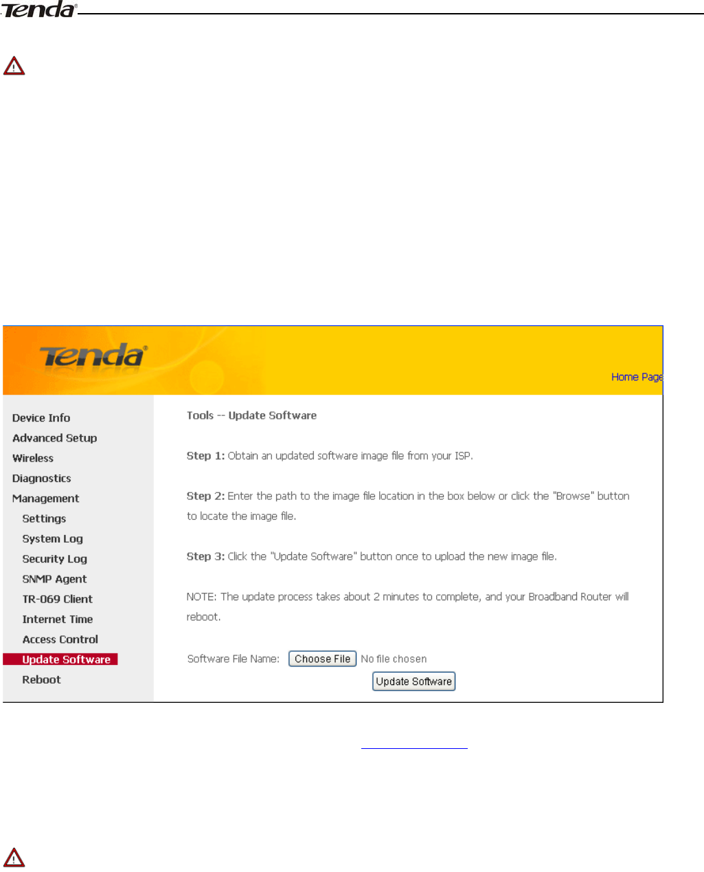
Wireless Modem Router User Guide
- 96 -
_________________________________________________________________________________________________
Note:
1. If you are not an advanced user, we suggest you keep the default settings.
2. To access the device from the LAN side, you must use the LAN IP address and log in as "admin" or "user"; to access
the device from the WAN side, you must use the WAN IP address and log in as "support".
_________________________________________________________________________________________________
4.5.8 Update Software
Firmware upgrade is released periodically to improve the functionality of your device and add any new features. If you
run into a problem with a specific feature of the device you could log in to our website (www.tendacn.com) to download
the latest firmware to update your device.
To update software, do as follows:
1. Obtain an updated software image file from our website: www.tendacn.com.
2. Enter the path to the image file location in the box below or click the "Browse" button to locate the image file.
3. Click the "Update Software" button once to upload the new image file.
_________________________________________________________________________________________________
Note:
The update process takes about 2 minutes to complete, and your Broadband Router will reboot.
_________________________________________________________________________________________________
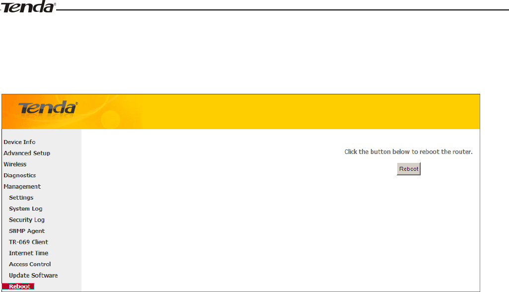
Wireless Modem Router User Guide
- 97 -
4.5.9 Reboot
Click the Reboot button to reboot the router.
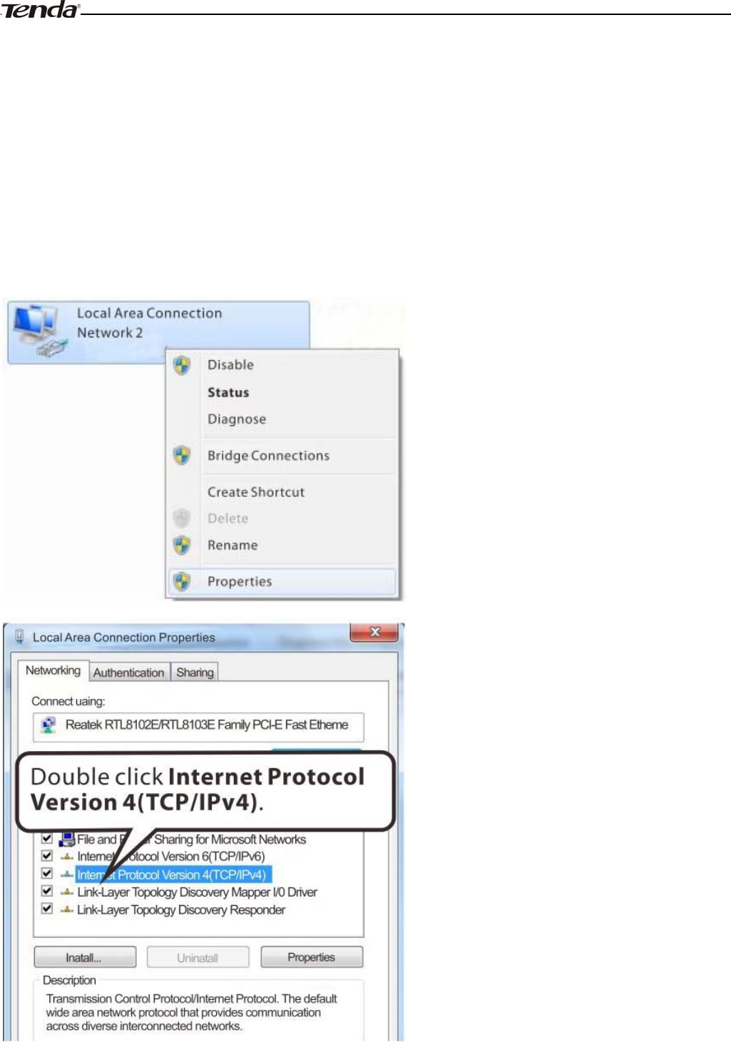
Wireless Modem Router User Guide
- 98 -
Appendix 1 Configure Your PC
Screens to configure TCP/IP properties in other Operating Systems are similar to those below.
Windows 7
Click Start-> Control Panel-> Network and Sharing Center-> Change adapter settings, select a desired Local Area
Connection and select Properties.
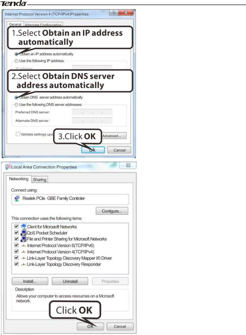
Wireless Modem Router User Guide
- 99 -
MAC
Click on the Apple icon from the top-left corner and select System Preferences.
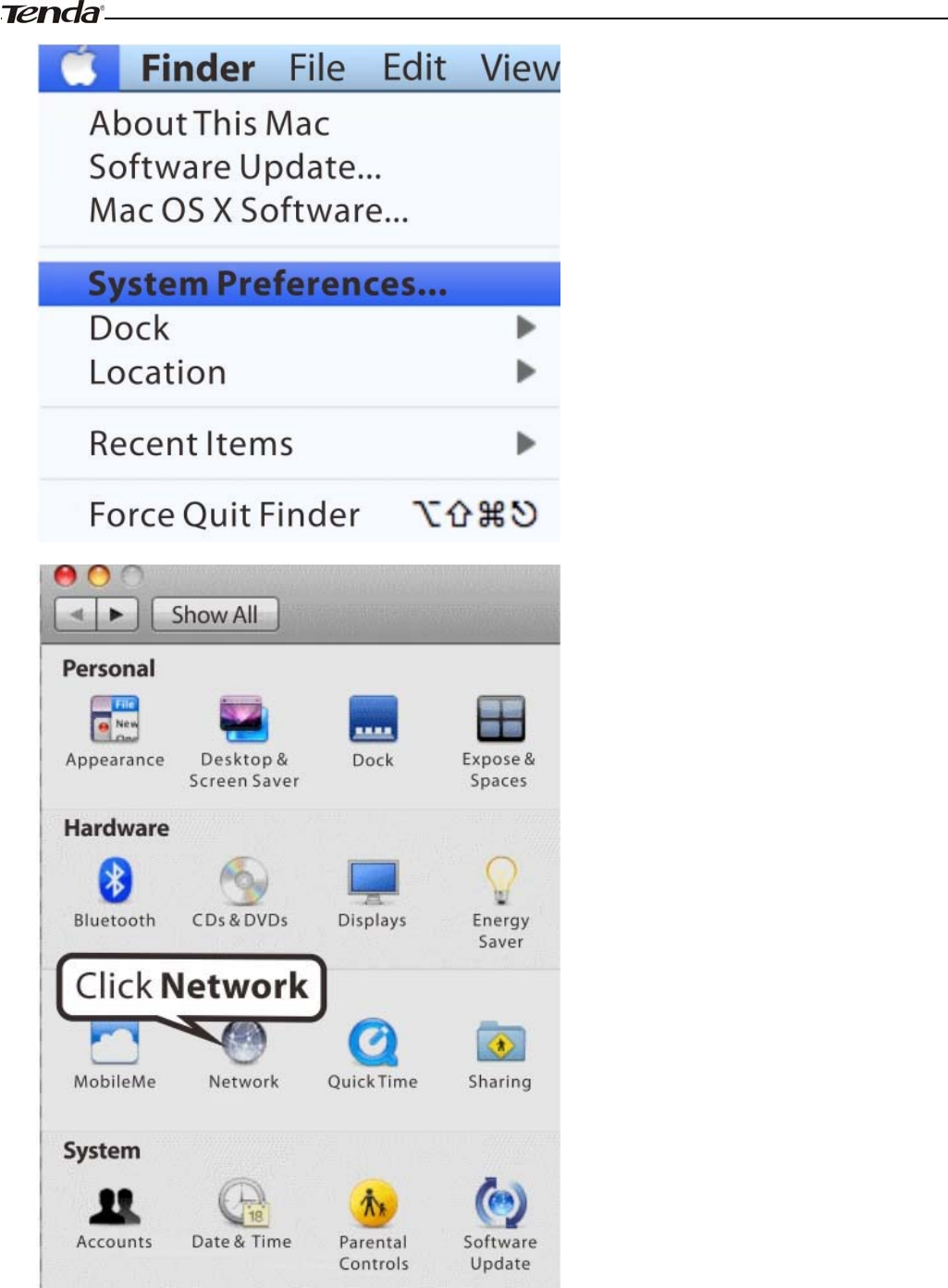
Wireless Modem Router User Guide
- 100 -
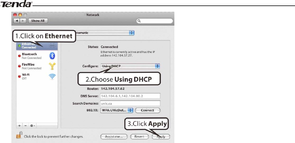
Wireless Modem Router User Guide
- 101 -
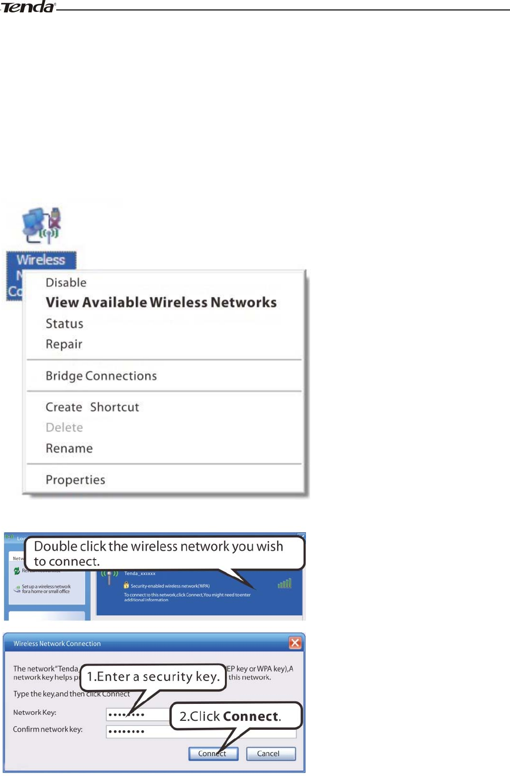
Wireless Modem Router User Guide
- 102 -
Appendix 2 Join Your Wireless Network
Windows XP
a). Click Start-> Settings -> Control Panel;
b). Double click Network Connections, select the desired wireless network connection and then click View Available
Wireless Networks.
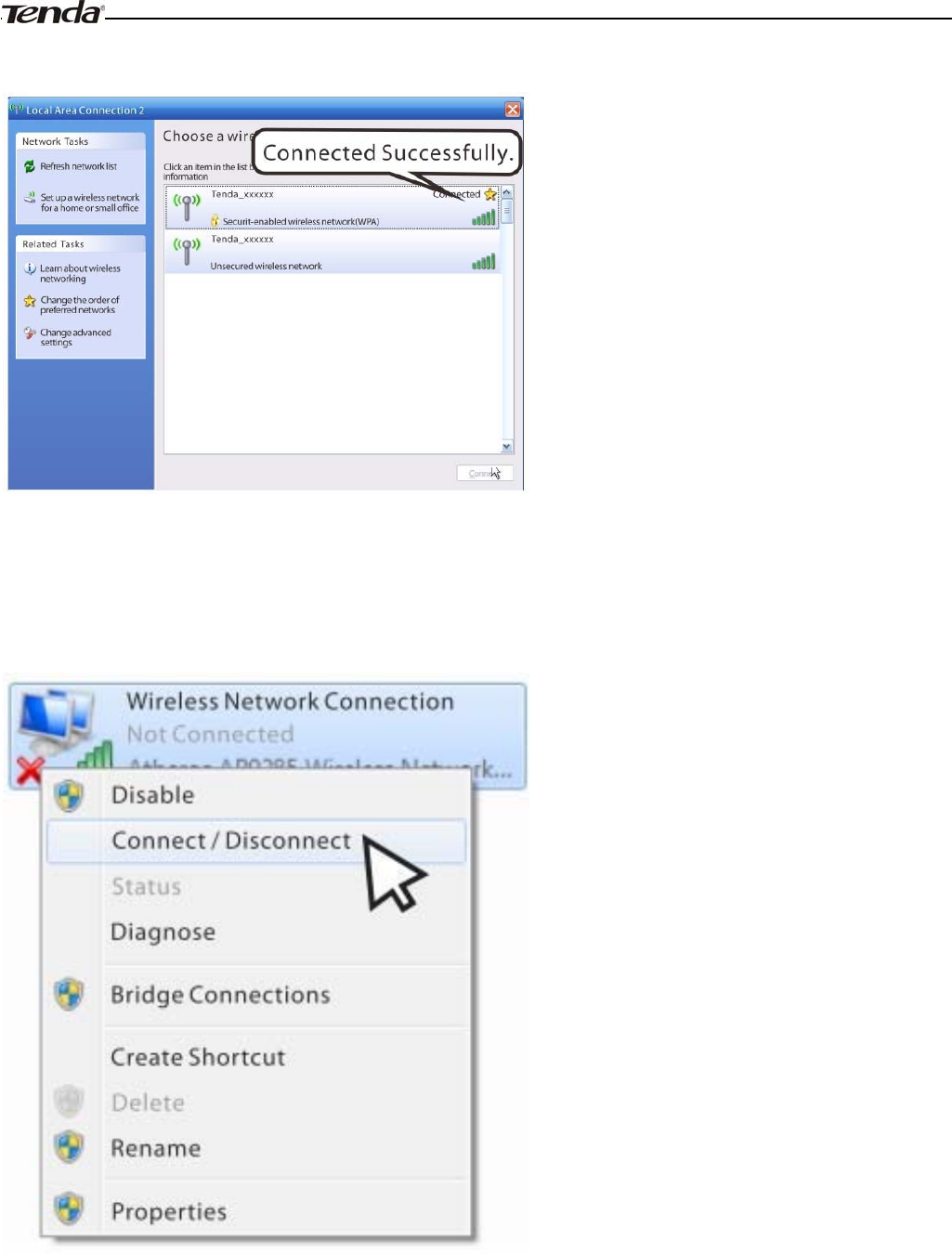
Wireless Modem Router User Guide
- 103 -
When you see Connected displayed next to the wireless network you selected, you have connected to the wireless
network successfully.
Windows 7
Click Start-> Control Panel-> Network and Sharing Center-> Change adapter settings, select a desired wireless
connection and click Connect/Disconnect.
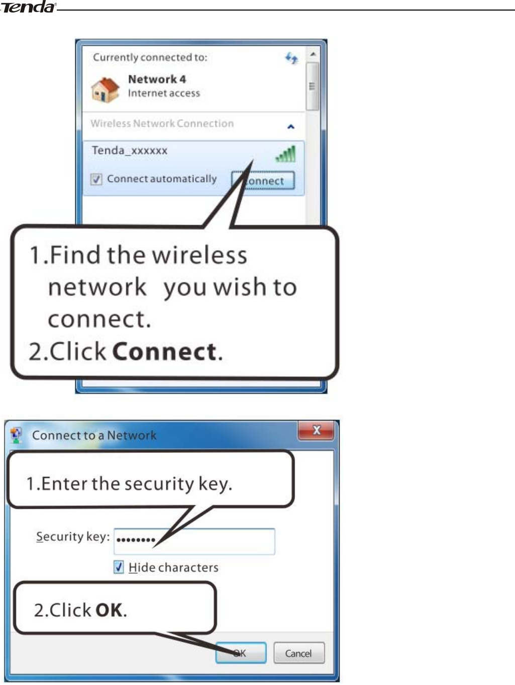
Wireless Modem Router User Guide
- 104 -
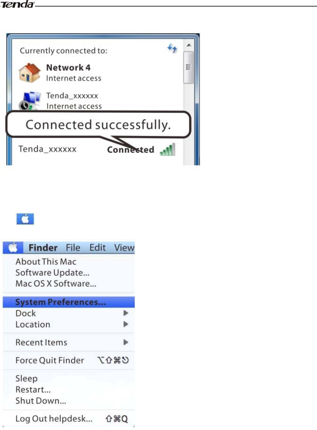
Wireless Modem Router User Guide
- 105 -
When you see Connected displayed next to the wireless network you selected, you have connected to the wireless
network successfully.
MAC
Click ->System Preferences.
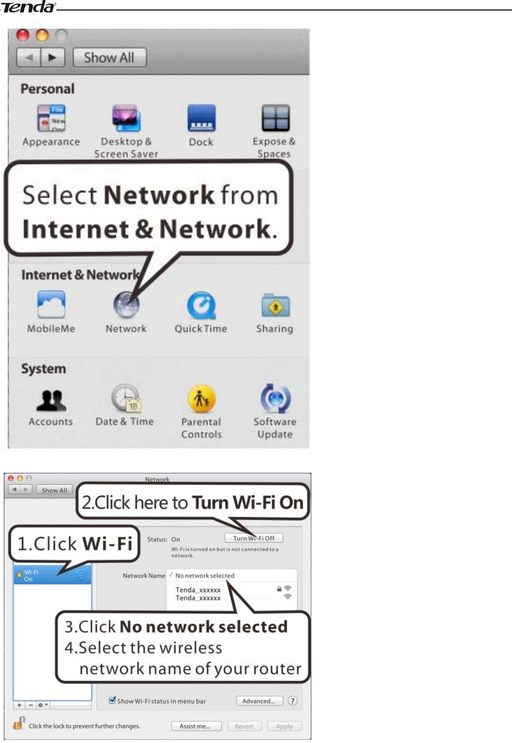
Wireless Modem Router User Guide
- 106 -
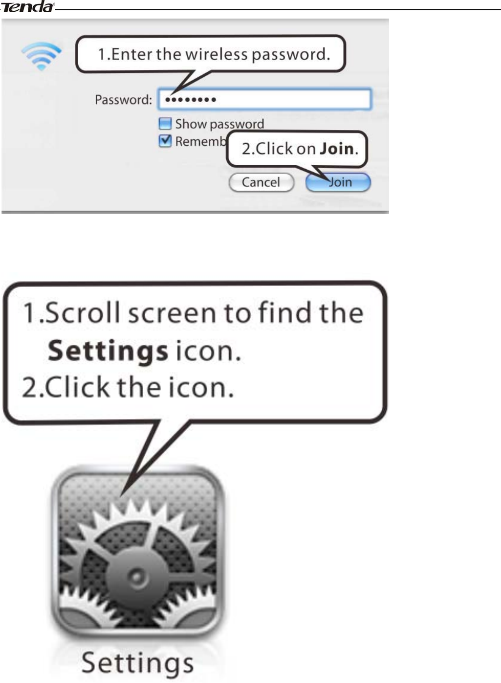
Wireless Modem Router User Guide
- 107 -
iPhone/iPad
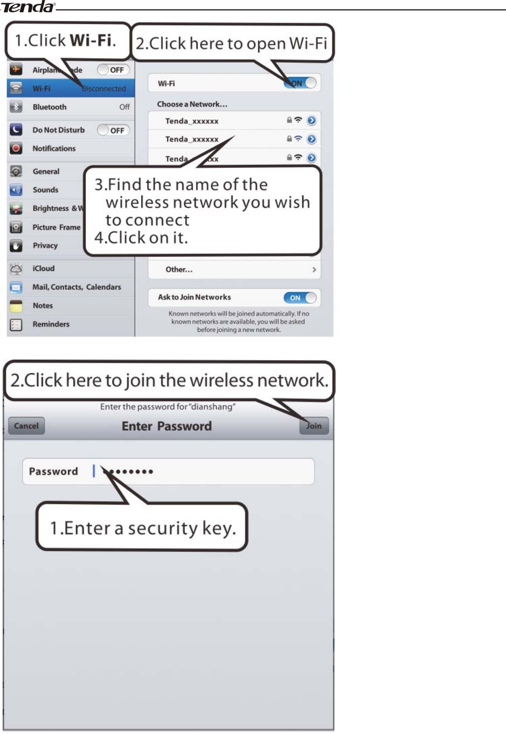
Wireless Modem Router User Guide
- 108 -
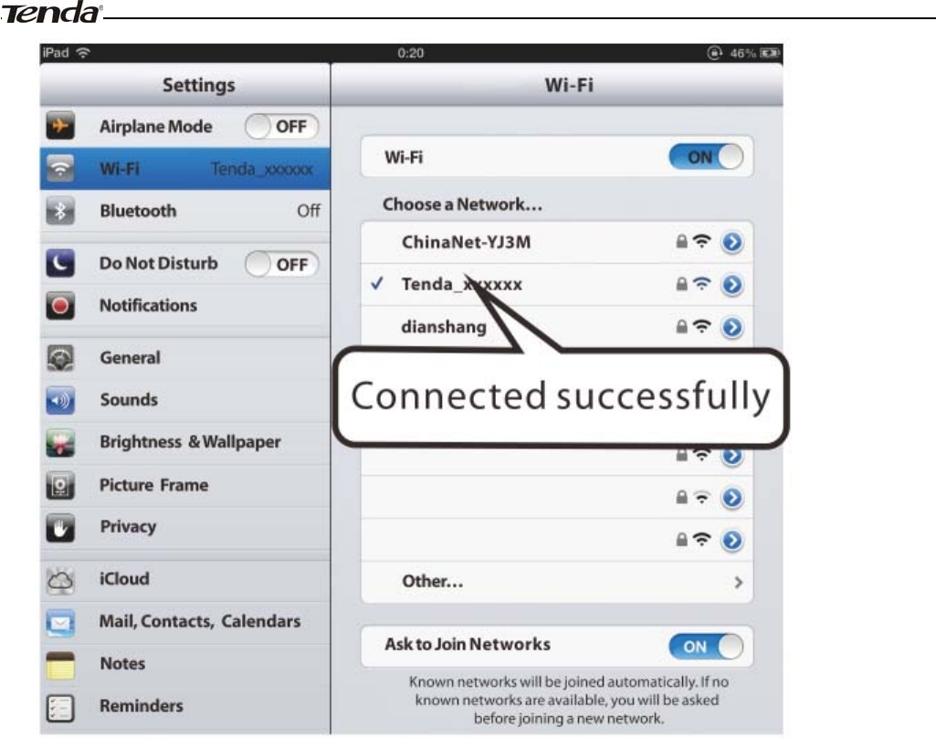
Wireless Modem Router User Guide
- 109 -

Wireless Modem Router User Guide
- 110 -
Appendix 3 FAQs
1. What information should I have to access Internet via the ADSL uplink?
If you have DSL broadband service, you might need the following information to set up your modem router.
• Active Internet service provided by an ADSL account
• The ISP configuration information for your DSL account
- ISP login name and password
- Fixed or static IP address
Depending on how your ISP set up your Internet account, you could need to know the Virtual path identifier (VPI) and
virtual channel identifier (VCI) parameters for a manual setup.
2. I cannot access the device's management interface. What should I do?
1. Verify the physical connection (namely, the Ethernet cable) between your PC and the device. For details, see
Hardware Install hereof.
2. Double check the TCP/IP settings on your PC. For details, see Appendix 1.Configure PC hereof.
3. Press the Reset button on the device and then re-access the management interface.
4. Change the Ethernet cable that connects your PC and the device.
5. Try accessing device management interface from other PCs, smart phones or iPads.
6. Connect your PC alone to one of the LAN ports on the device.
3. I forget the wireless security key. What should I do? (How do I configure or change the security key?)
1. Try the default security key, which can be seen from the label attached to the device bottom.
2. If step 1 that works, access the device web manager and customize a new security key.
3. If step 1 does not work, press the Reset button on the device to restore factory default settings. And then log in to
the device web manager to customize a new security key.
4. My notebook is unable to search wireless networks, what should I do?
1. Verify that wireless service is enabled on your notebook by checking the wireless hardware or software button on your
notebook. The hardware button is usually located on the side of your notebook. Note that some notebooks may not have
such hardware button. Software button can be implemented by pressing Fn+ .Fn is situated on the bottom left corner
of your keyboard, may be any key between F1-F12 depending on what type of keyboard you are using.
2. Log in to the device, select Advanced-> Wireless-> Basic and change the wireless network name (SSID). Then
search again.
3. Follow below steps to verify that wireless service is enabled on your notebook (for Windows XP OS only).
From the desktop, right-click on the My Computer icon and select Manage. Select Services and Applications, double
click Services and view the status of Wireless Zero Configuration. If Status dose not display Started, right click the
Wireless Zero Configuration and select Start; if Startup Type displays Disabled, right click the Wireless Zero
Configuration, select Properties; from the Startup Type drop-down list box, select Automatic and then click Start in
Service Status.
5. Why cannot I connect to the searched wireless network?
1. Verify that you entered a correct security key.
2. Log in to the device, select Advanced-> Wireless and change the wireless network name (SSID). Then connect again.
3. Log in to the device, select Advanced-> Wireless-> Security and change the security settings. Then connect again.

Wireless Modem Router User Guide
- 111 -
6. Where should I place the wireless device for optimum performance?
1. Place it in the center to extend wireless coverage as far as possible.
2. Never place the device near to metal objects or in direct sunshine.
3. Keep it far away from devices that use the 2.4 GHz radio wave frequency to transmit and receive data, such as
802.11g/n wireless network devices, electronic devices such as cell phones, radio transmitters, blue tooth, cordless
phones, fax machine, refrigerator and microwaves to avoid electronic interference.

Wireless Modem Router User Guide
- 112 -
Appendix 4 VPI/VCI List
The following table lists common ISPs and their VPI and VCI numbers. If you cannot locate your ISP and their VPI and
VCI information here, ask your ISP to provide it.
Country ISP VPI VCI Encapsulation
Australia Telstra 835 PPPoA LLC
Australia GoldenIT 835 _PPPOA_VCMUX
Australia Telstra Bigpond 835 PPPOE_LLC
Australia OptusNET 835 PPPOE_VCMUX
Australia AAPT 835 PPPOE_VCMUX
Australia ADSL Direct 835 PPPOE_LLC
Australia Ausie Broadband 835 PPPOE_LLC
Australia Australia On Line 835 PPPOA_VCMUX
Australia Connexus 835 PPPOE_LLC
Australia Dodo 835 PPPOE_LLC
Australia Gotalk 835 PPPOE_VCMUX
Australia Internode 835 PPPOE_VCMUX
Australia iPrimus 835 PPPOA_VCMUX
Australia Netspace 835 PPPOE_VCMUX
Australia Southern Cross Telco 835 PPPOE_LLC
Australia TPG Internet 835 PPPOE_LLC
Argentina Telecom 033 PPPoE LLC
Argentina Telefonica 8 35 PPPoE LLC
Argentina 133 PPPoA VC-MUX
Belgium ADSL Office 835 1483 Routed IP LLC
Belgium Turboline 835 PPPoA LLC
Bolivia 034 1483 Routed IP LLC
Brazil Brasil Telcom 035 PPPoE LLC
Brazil Telefonica 8 35 PPPoE LLC
Brazil Telmar 033 PPPoE LLC
Brazil South Region 132 PPPoE LLC
Colombia EMCALI 033 PPPoA VC-MUX
Columbia ETB 033 PPPoE LLC
Costa Rica ICE 150 1483 Routed IP LLC
Denmark Cybercity, Tiscali 035 PPPoA VC-MUX
France (1) Orange 835 PPPoE LLC
France (2) 867 PPPoE LLC
France (3) SFR 835 PPPoA VC-MUX
Germany 132 PPPoE LLC
Hungary Sci-Network 035 PPPoE LLC

Wireless Modem Router User Guide
- 113 -
Iceland Islandssimi 035 PPPoA VC-MUX
Iceland Siminn 848 PPPoA VC-MUX
Israel 835 PPPoA VC-MUX
Italy 835 PPPoA VC-MUX
Iran (1) 035 PPPoE LLC
Iran (2) 881 PPPoE LLC
Israel(1) 848 PPPoA VC-MUX
Jamaica (1) 835 PPPoA VC-MUX
Jamaica (2) 035 PPPoA VC-MUX
Jamaica (3) 835 1483 Bridged IP LLC SNAP
Jamaica (4) 035 1483 Bridged IP LLC SNAP
Kazakhstan 033 PPPoA VC-MUX
Malaysia 035 PPPoE LLC
Mexico Telmex (1) 881 PPPoE LLC
Mexico Telmex (2) 835 PPPoE LLC
Mexico Telmex (3) 081 PPPoE LLC
Mexico Telmex (4) 035 PPPoE LLC
Netherlands BBNED 035 PPPoA VC-MUX
Netherlands MX Stream 848 PPPoA VC-MUX
New Zealand Xtra 035 PPPoA VC-MUX
New Zealand Slingshot 0100 PPPoA VC-MUX
Pakistan (cyber net) 835 PPPoE LLC
Pakistan (linkDotnet) 035 PPPoA LLC
Pakistan(PTCL) 881 PPPoE LLc
Portugal 035 PPPoE LLC
Puerto Rico Coqui.net 035 PPPoA LLC
Saudi Arabia (1) 033 PPPoE LLC
Saudi Arabia (2) 035 PPPoE LLC
Saudi Arabia (3) 033 1483 Bridged IP LLC
Saudi Arabia (4) 033 1483 Routed IP LLC
Saudi Arabia (5) 035 1483 Bridged IP LLC
Saudi Arabia (6) 035 1483 Routed IP LLC
Spain Albura, Tiscali 132 PPPoA VC-MUX
Spain Colt Telecom, Ola Internet 035 PPPoA VC-MUX
Spain EresMas, Retevision 835 PPPoA VC-MUX
Spain Telefonica (1) 832 PPPoE LLC
Spain Telefonica (2), Terra 832 1483 Routed IP LLC
Spain Wanadoo (1) 835 PPPoA VC-MUX
Spain Wanadoo (2) 832 PPPoE LLC
Spain Wanadoo (3) 832 1483 Routed IP LLC
Sweden Telenordia 835 PPPoE
Sweden Telia 835 1483 Routed IP LLC
Switzerland 835 PPPoE LLC
Trinidad & Tobago TSTT 035 PPPoA VC-MUX

Wireless Modem Router User Guide
- 114 -
Turkey (1) 835 PPPoE LLC
Turkey (2) 835 PPPoA VC-MUX
Thailand TRUE 0100 PPPoE LLC
Thailand TOT 132 PPPoE LLC
Thailand 3BB 033 PPPoE LLC
Thailand Cat Telecom 035 PPPoE LLC
Thailand BuddyBB 035 PPPoE LLC
United States 4DV.Net 0 32 PPPoA VC-MUX
United States All Tel (1) 0 35 PPPoE LLC
United States All Tel (2) 0 35 1483 Bridged IP LLC
United States Ameritech 8 35 PPPoA LLC
United States AT&T (1) 0 35 PPPoE LLC
United States AT&T (2) 8 35 1483 Bridged IP LLC
United States AT&T (3) 0 35 1483 Bridged IP LLC
United States August.net (1) 0 35 1483 Bridged IP LLC
United States August.net (2) 8 35 1483 Bridged IP LLC
United States BellSouth 8 35 PPPoE LLC
United States Casstle.Net 0 96 1483 Bridged IP LLC
United States CenturyTel (1) 8 35 PPPoE LLC
United States CenturyTel (2) 8 35 1483 Bridged IP LLC
United States Coqui.net 0 35 PPPoA LLC
United States Covad 0 35 PPPoE LLC
United States Earthlink (1) 0 35 PPPoE LLC
United States Earthlink (2) 8 35 PPPoE LLC
United States Earthlink (3) 8 35 PPPoE VC-MUX
United States Earthlink (4) 0 32 PPPoA LLC
United States Eastex 0 100 PPPoA LLC
United States Embarq 8 35 1483 Bridged IP LLC
United States Frontier 0 35 PPPoE LLC
United States Grande Communications 1 34 PPPoE LLC
United States GWI 0 35 1483 Bridged IP LLC
United States Hotwire 0 35 1483 Bridged IP LLC
United States Internet Junction 0 35 1484 Bridged IP LLC
United States PVT 0 35 1485 Bridged IP LLC
United States QWest (1) 0 32 PPPoALLC
United States QWest (2) 0 32 PPPoA VC-MUX
United States QWest (3) 0 32 1483 Bridged IP LLC
United States QWest (4) 0 32 PPPoE LLC
United States SBC (1) 0 35 PPPoE LLC
United States SBC (2) 0 35 1483 Bridged IP LLC
United States SBC (3) 8 35 1483 Bridged IP LLC
United States Sonic 0 35 1484 Bridged IP LLC
United States SouthWestern Bell 0 35 1483 Bridged IP LLC
United States Sprint (1) 0 35 PPPoALLC

Wireless Modem Router User Guide
- 115 -
United States Sprint (2) 8 35 PPPoE LLC
United States Sprint Territory 0 35 PPPoE LLC
United States SureWest
Communications(1) 0 34 1483 Bridged LLC Snap
United States SureWest
Communications(2) 0 32 PPPoE LLC
United States SureWest
Communications(3) 0 32 PPPoA LLC
United States Toast.Net 0 35 PPPoE LLC
United States Uniserv 0 33 1483 Bridged IP LLC
United States US West 0 32 PPPoA VC-MUX
United States Verizon (1) 0 35 PPPoE LLC
United States Verizon (2) 0 35 1483 Bridged IP LLC
United States Windstream 0 35 PPPoE LLC
Canada Primus Canada 035 PPPoE LLC
Canada Rogers Canada (1) 035 PPPoE LLC
Canada Rogers Canada (2) 835 1483 Bridged IP LLC
Canada Rogers Canada (3) 035 1484 Bridged IP LLC
Canada BellSouth(1) Canada 835 PPPoE LLC
Canada BellSouth(2) Canada 035 PPPoE LLC
Canada Sprint (1) Canada 035 PPPoA LLC
Canada Sprint (2) Canada 835 PPPoE LLC
Canada Verizon (1) Canada 035 PPPoE LLC
Canada Verizon (2) Canada 035 1483 Bridged IP LLC
United States Verizon (2) 035 1483 Bridged IP LLC
United Kingdom (1) 038 PPPoA VC-MUX
United Kingdom (2) 038 PPPoE LLC
United Kingdom AOL 038 PPPoE VC-MUX
United Kingdom Karoo 150 PPPoA LLC
Venezuela CANTV 033 1483 Routed IP LLC
Vietnam 035 PPPoE LLC
Vietnam VDC 835 PPPoE LLC
Vietnam Viettel 835 PPPoE LLC
Vietnam FPT 033 PPPoE LLC
Russia Rostel 035 PPPoE LLC
Russia Port telecom 035 PPPoE LLC
Russia VNTC 835 PPPoE LLC
Uzbekistan Sharq Stream 835 PPPoE LLC
Uzbekistan Sarkor 033 PPPoE LLC
Uzbekistan TShTT 035 PPPoE LLC
Kazakhstan Kazakhtelecom
«Megaline» 040 LLC/SNAP Bridging
Spain Arrakis 035 1483 Bridged IP VC-MUX
Spain Auna 835 1483 Bridged IP VC-MUX

Wireless Modem Router User Guide
- 116 -
Spain Comunitel 033 1483 Bridged IP VC-MUX
Spain Eresmas 835 1483 Bridged IP VC-MUX
Spain Jazztel 835 IPOE VC-MUX
Spain Jazztel ADSL2+ /
Desagregado 835 1483 Bridged IP
LLC-BRIDGING
Spain OpenforYou 832 1483 Bridged IP VC-MUX
Spain Tele2 835 1483 Bridged IP VC-MUX
Spain Telefónica (España) 832 1483 Bridged IP
LLC/SNAP
Telefónica (Argentina) 835 1483 Bridged IP LLC-based
Telefónica (Perú) 848 1483 Bridged IP VC-MUX
Spain Terra 832 1483 Bridged IP LLC/SNAP
Spain Terra 832 1483 Bridged IP LLC/SNAP
Spain Uni2 133 1483 Bridged IP VC-MUX
Spain Orange 835 1483 Bridged IP VC-MUX
Spain Orange 20 Megas 835 LLC-BRIDGING
Spain Orange 832 1483 Bridged IP LLC/SNAP
Spain Ya.com 832 1483 Bridged IP VC - MUX
Spain Ya.com 832 1483 Bridged IP LLC/SNAP
France Free 836 LLC
Netherlands MXSTREAM 848 1483 Bridged IP LLC
Netherlands BBNED 035 1483 Bridged IP LLC
Belgium Turboline 835 1483 Bridged IP LLC
Belgium ADSL Office 835 1483 Bridged IP LLC
UK 038 1483 Bridged IP LLC
Italy 835 1483 Bridged IP LLC
Switzerland 835 1483 Bridged IP LLC
SpainWanadoo 832 1483 Bridged IP LLC
Czech Republic 848 1483 Bridged IP LLC
Dubai 050 1483 Bridged IP LLC
UAE (Al sahmil) 050 1483 Bridged IP LLC
Egypt: TE-data 035 1483 Bridged IP LLC
Egypt: Linkdsl 035 1483 Bridged IP LLC
Egypt: Vodafone 835 1483 Bridged IP LLC
kuwait unitednetwork 033 1483 Bridged IP LLC
Pakistan (PALESTINE) ʳ835 1483 Bridged IP LLC
Dominican Republic 033 1483 Bridged IP LLC
Orange Nyumbani
(Kenya)
035 PPPoE LLC
Pakistan for PTCL 0103 1483 Bridged IP LLC
Sri Lanka Telecom-(SLT) 835 PPPOE LLC
Philippines(1) 035 1483 Bridged IP LLC
Philippines(2) 0100 1483 Bridged IP LLC
RomTelecom Romania: 035 1483 Bridged IP LLC

Wireless Modem Router User Guide
- 117 -
Finland Saunalahti 0100 1483 Bridged IP LLC
Finland Elisa 0100 1483 Bridged IP LLC
Finland DNA 0100 1483 Bridged IP LLC
Finland Sonera 035 1483 Bridged IP LLC
Iran [Shatel]
Aria-Rasaneh-Tadbir 035 PPPOE LLC
Iran Asia-Tech 035 PPPOE LLC
Iran Pars-Online (Tehran) 0 35 PPPOE LLC
Iran Pars-Online (Provinces) 059 PPPOE LLC
Iran [Saba-Net]
Neda-Gostar-Saba 035 PPPOE LLC
Iran Pishgaman-Tose 035 PPPOE LLC
Iran Fan-Ava 835 PPPOE LLC
Iran Datak 035 PPPOE LLC
Iran Laser (General) 035 PPPOE LLC
Iran Laser (Privates) 032 PPPOE LLC
Iran Asr-Enteghal-Dadeha 835 PPPOE LLC
Iran Kara-Amin-Ertebat 033 PPPOE LLC
Iran ITC 035 PPPOE LLC
Iran Dadegostar Asre Novin 033 PPPOE LLC
India Airtel 132 1483 Bridged IP LLC
India BSNL 035 1483 Bridged IP LLC
India MTNL 035 1483 Bridged IP LLC
India RELIANCE
COMMUNICATION 035 PPPOE LLC
India TATA INDICOM 032 PPPOE LLC
India CONNECT 132 PPPOE LLC
morocco IAM 835 PPPOE
Malaysia Streamyx 035 PPPOE LLC
Indonesia Speedy
Telkomnet
ʳ881 PPPoE LLC

Wireless Modem Router User Guide
- 118 -
Appendix 5 Regulatory Compliance Information
CE Mark Warning
This is a Class B product In a domestic environment,this product may cause radio interference,in which case the user
may be required to take adequate measures.This device complies with EU 1999/5/EC.
NOTE:(1)The manufacturer is not responsible for any radio or TV interference caused by unauthorized modifications to
this equipment.(2) To avoid unnecessary radiation interference, it is recommended to use a shielded RJ45 cable
FCC Statement
This device complies with Part 15 of the FCC Rules. Operation is subject to the following two conditions: (1) This
device may not cause harmful interference, and (2) this device must accept any interference received, including
interference that may cause undesired operation.
This equipment has been tested and found to comply with the limits for a Class B digital device, pursuant to Part 15 of
the FCC Rules. These limits are designed to provide reasonable protection against harmful interference in a residential
installation. This equipment generates, uses and can radiate radio frequency energy and, if not installed and used in
accordance with the instructions, may cause harmful interference to radio communications. However, there is no
guarantee that interference will not occur in a particular installation. If this equipment does cause harmful interference
to radio or television reception, which can be determined by turning the equipment off and on, the user is encouraged to
try to correct the interference by one of the following measures:
ȍ Reorient or relocate the receiving antenna.
ȍ Increase the separation between the equipment and receiver.
ȍ Connect the equipment into an outlet on a circuit different from that
to which the receiver is connected.
ȍ Consult the dealer or an experienced radio/TV technician for help.
FCC Caution: Any changes or modifications not expressly approved by the party responsible for compliance could void
the user's authority to operate this equipment.

Wireless Modem Router User Guide
- 119 -
This transmitter must not be co-located or operating in conjunction with any other antenna or transmitter.
The manufacturer is not responsible for any radio or TV interference caused by unauthorized modifications to this
equipment.
Radiation Exposure Statement
This equipment complies with FCC radiation exposure limits set forth for an uncontrolled environment. This equipment
should be installed and operated with minimum distance 20cm between the radiator & your body.
NOTE: (1)The manufacturer is not responsible for any radio or TV interference caused by unauthorized modifications to
this equipment.(2) To avoid unnecessary radiation interference, it is recommended to use a shielded RJ45 cable