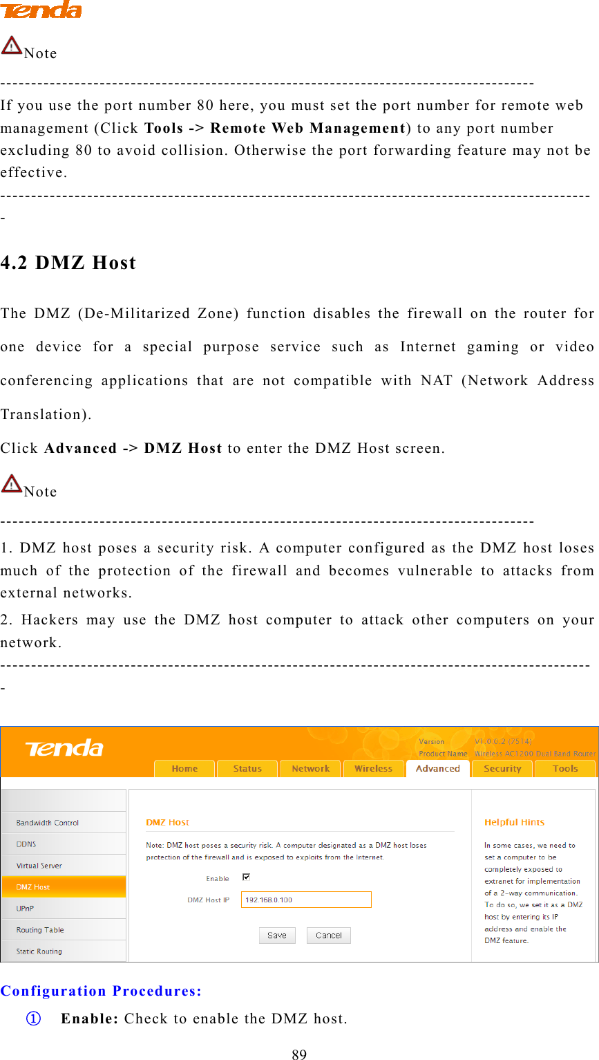
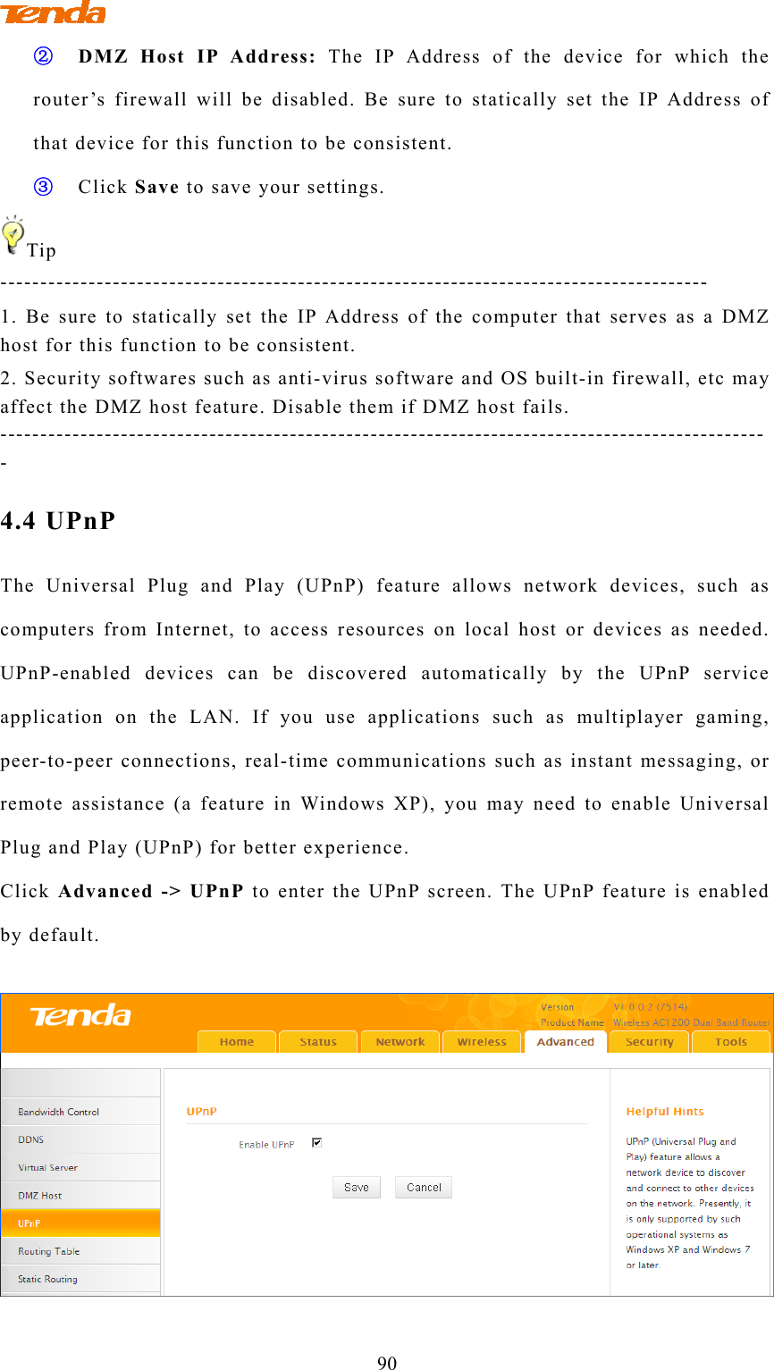
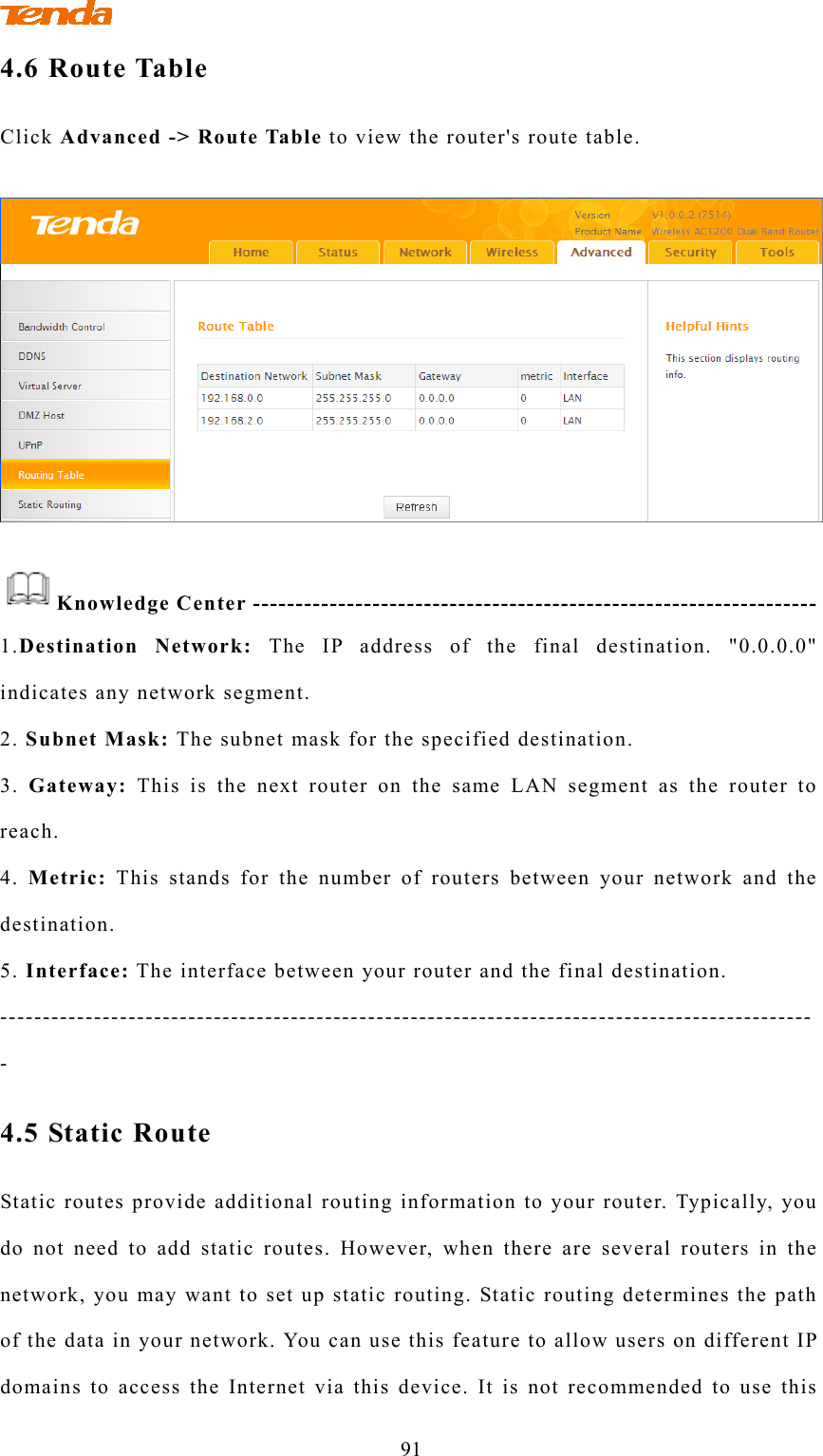
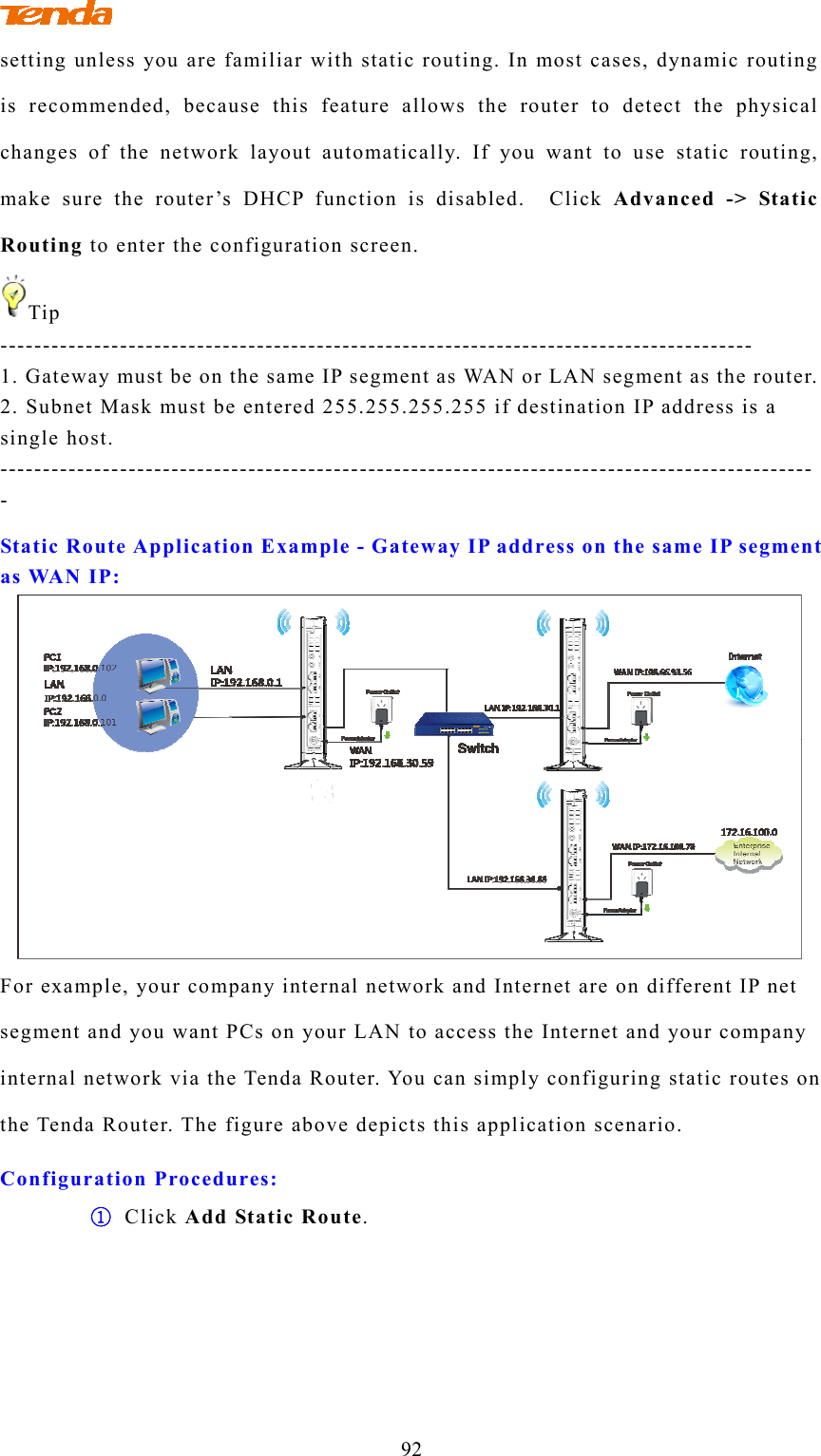
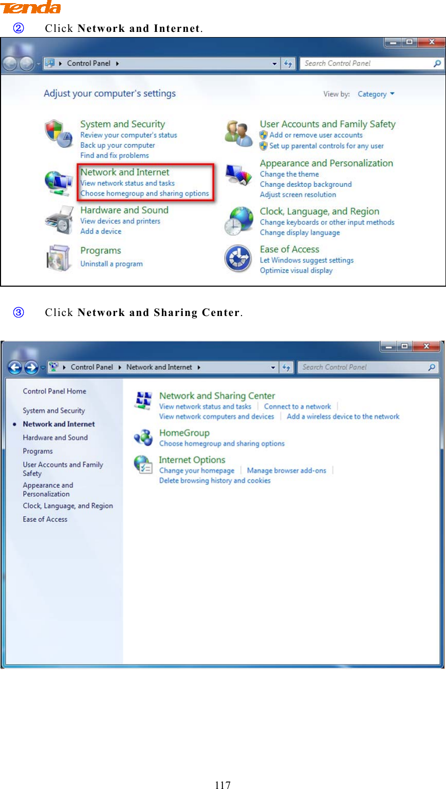
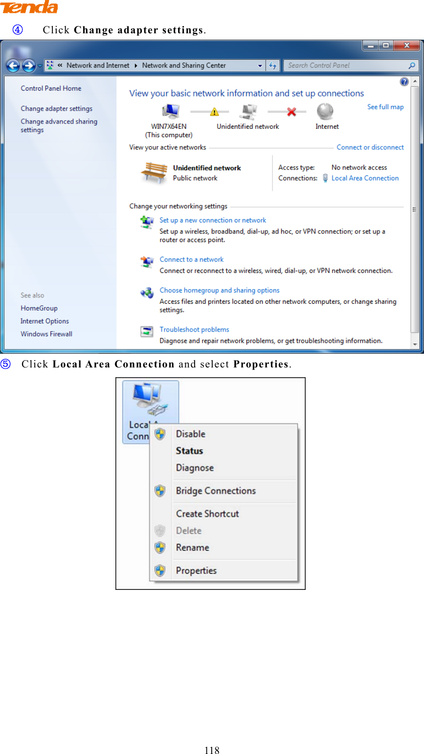
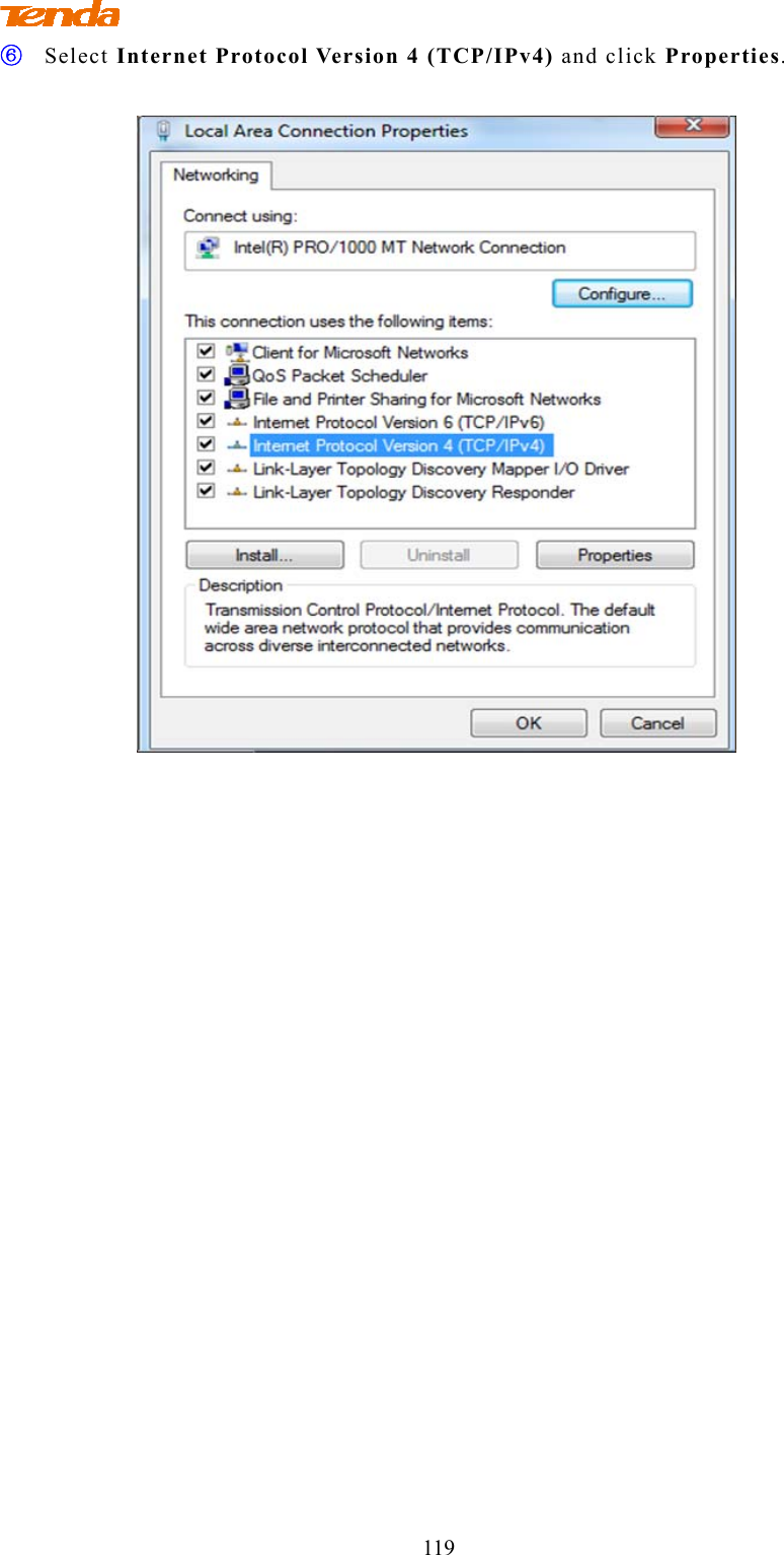
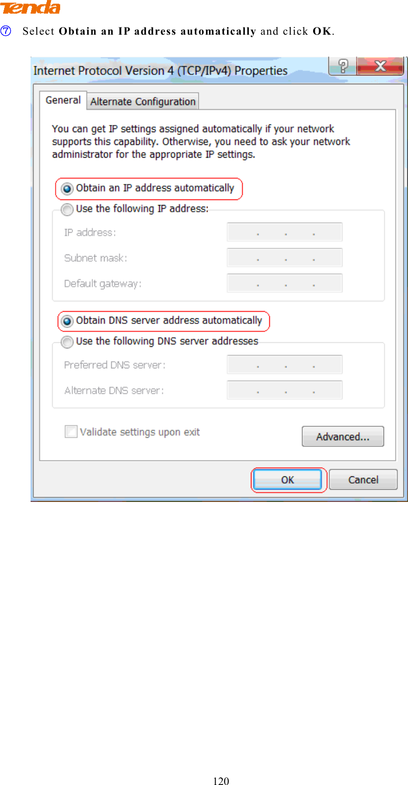
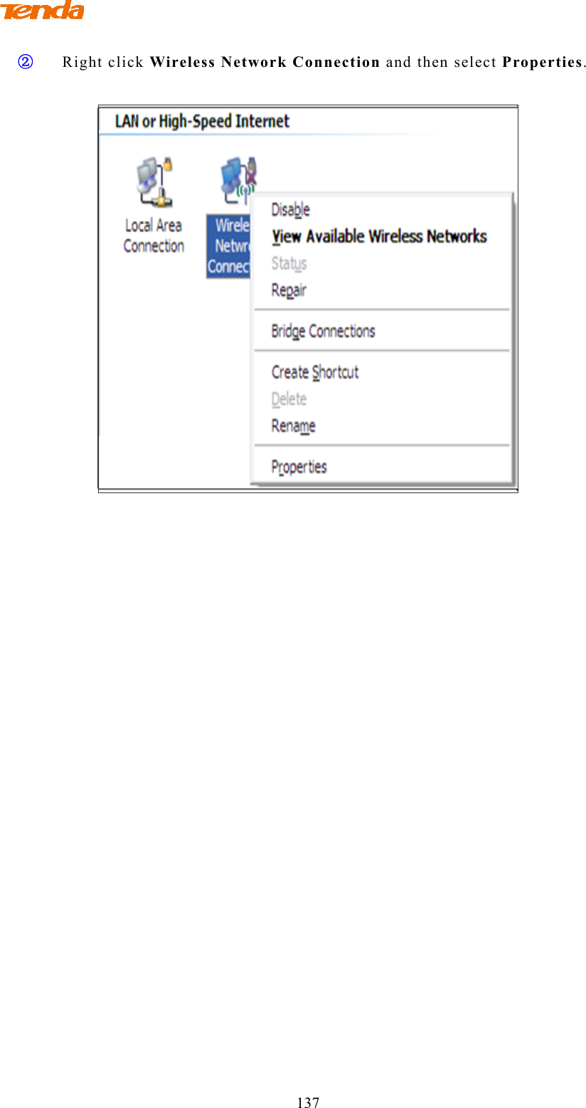
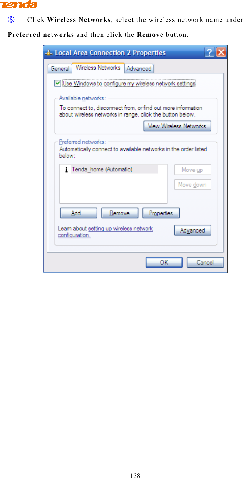
TENDA TECHNOLOGY F1200 Wireless AC1200 Dual-band Router User Manual part2

SHENZHEN TENDA TECHNOLOGY CO., LTD. Wireless AC1200 Dual-band Router part2
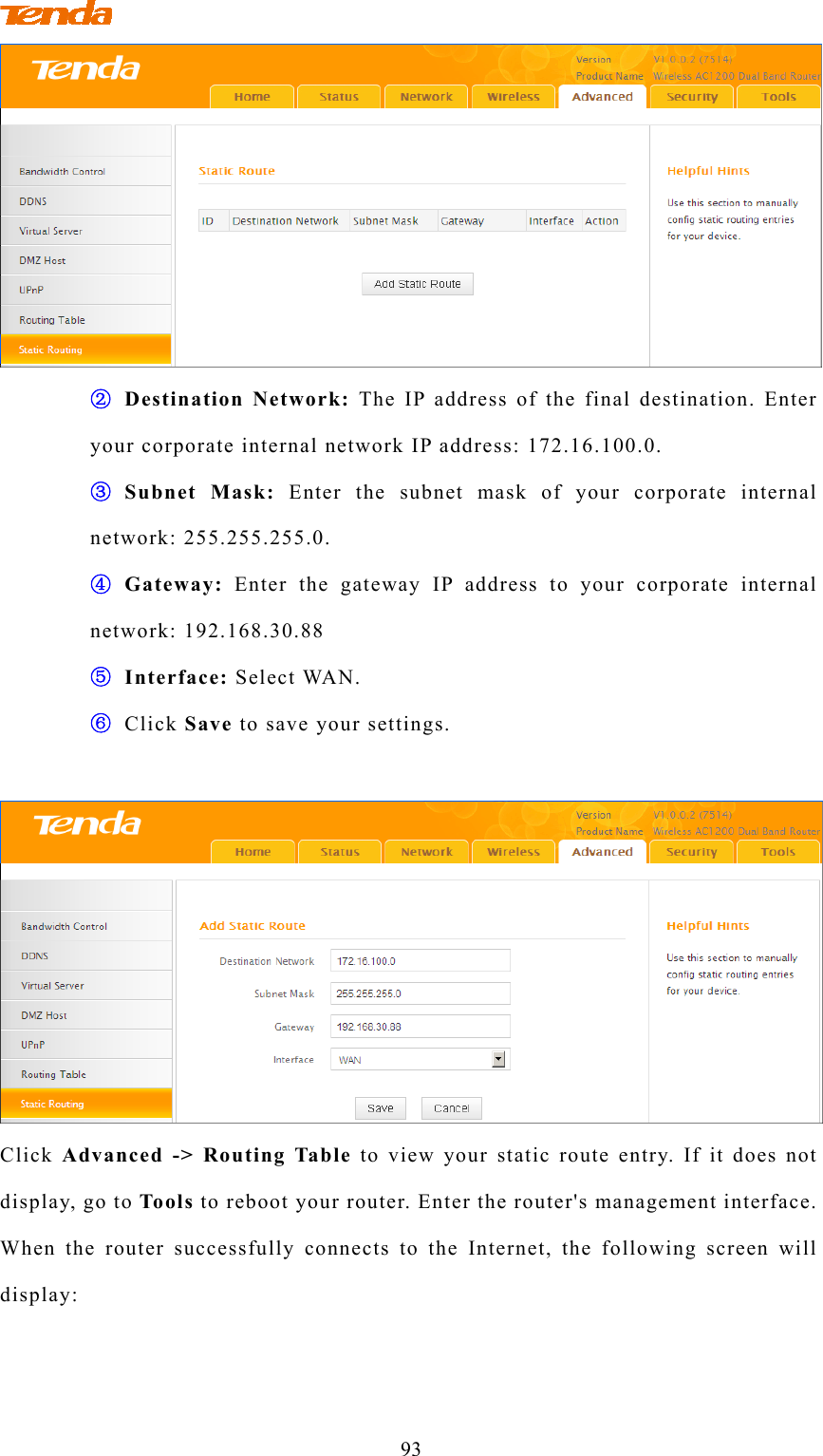
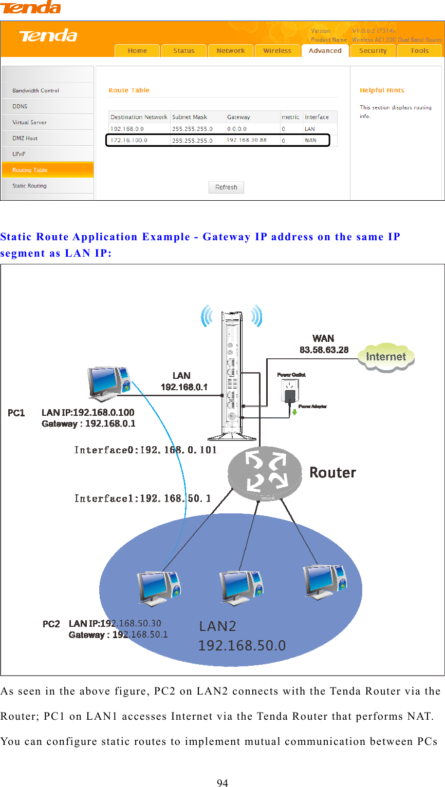
Contents

User Manual_part2

                         69 ② Click OK in the appearing screen. ③ Click  Wireless -> Wireless Extender, select WDS Mode from the Mode drop-down list, select Wireless AP from the WDS Mode drop-down list and then click Open Scan.  ④ Search for and select the base station AP's SSID and then click Close Scan.
                         70  ⑤   The SSID, channel, MAC address, security settings except security key of the base station AP will be automatically added to the corresponding fields. You only need to enter the security key of the base station AP and click Save.  ⑥ Click Network -> DHCP Server, disable the DHCP server there and
                         71 then click Save.   Note ------------------------------------------------------------------------------------- 1.To set up a wireless network with WDS, both access points must be WDS capable. 2.This router's primary SSID will automatically change to match that of the remote router when the WDS feature is configured successfully. Please do not change this SSID. Changing this SSID may interrupt the wireless bridge link. 3.  When the WDS is configured successfully, wireless clients can connect to this Tenda wireless router's SSID for Internet access. ----------------------------------------------------------------------------------------------- Verify Bridge Connectivity: ① Connect your PC to this Tenda wireless router via a wired or wireless connection and set it to "Obtain an IP address automatically". If you are not clear, see Appendix 1 Configure PC TCP/IP Setting. ② Wait until your PC successfully obtains an IP address.
                         72   Last number differs from that of the remote wireless router's LAN IP address. This is the remote router's LAN IP address.
                                       73 ③ Click Start ->Run.  ④ Enter cmd and click OK.   ⑤ Enter "ping default gateway IP address". Here in this example, enter "ping 192.168.0.1" and press Enter. If you see a similar screen (highlighted area), the bridge is established successfully.
                                       74  3.5 Access Control Specify a list of devices to "Permit" or "Forbid" a connection to your wireless network via the devices’ MAC Addresses. Click Wireless -> Wireless Access Control to enter the configuration screen. There are three options available: Disable, Deny Access to Wireless Network and Allow Access to Wireless Network.    A. If you want to allow all wireless clients to join your wireless network, select Disable.  B. If you want to allow ONLY the specified wireless clients to join your wireless
                                       75 network, select Allow Access to Wireless Network.   C.  If you want to disallow ONLY the specified wireless clients to join your wireless network, select Deny Access to Wireless Network.   Wireless Access Control Application Example: To only allow your own notebook at the MAC address of C8:3A:35:C2:CA:E7 to join your wireless network (SSID:Tenda_home)  Configuration Procedures: ① Select the wireless band you wish to use, for example 2.4Ghz. ② Click Enable. ③ Select Allow Access to Wireless Network.  ④ Click Add.
                                       76   ⑤ Select or enter your wireless MAC address and click Save.  ⑥ Below screen will then appear.
                                       77  Tip --------------------------------------------------------------------------------------- 1. Up to 16 wireless MAC addresses can be configured. 2. If you don't want to configure the complex wireless security settings and want to disallow others to join your wireless network, you can configure a wireless access control rule to allow only your own wireless device. -----------------------------------------------------------------------------------------------
                                        78 3.7 WPS Setup Click Wireless -> WPS to enter WPS screen. Wi-Fi Protected Setup makes it easy for home users who know little of wireless security to establish a secure wireless home network, as well as to add new devices to an existing network without entering long passphrases or configuring complicated settings. Simply enter a PIN code or press the software PBC button or hardware WPS button (if equipped) and a secure wireless connection can be established. A. If your wireless network is not secured, you can use the WPS to quickly encrypt your wireless. B. If your wireless network is secured with WPS, you can quickly join your wireless network with a WPS capable adapter (Only WPA2-PSK and Mixed WPA/WPA2-PSK are supported). You can use WPS PBC or WPS PIN to establish a secure connection.  PBC:  Establish WPS connection using the the software PBC button or hardware WPS button (if equipped).  PIN: Establish WPS connection using the PIN code. To secure a wireless network with WPS Knowledge Center ------------------------------------------------------------------ 1. Reset OOB:  If clicked, the device's SSID and security mode will become unconfigured so that WPS can reconfigure the device's SSID, security settings. When the action of Reset OOB completes, the device's SSID will be restored to factory default, and security mode will be disabled (none). -----------------------------------------------------------------------------------------------
                                        79   You can use the following 4 methods to establish a WPS connection: Method 1: Establish a WPS connection using PBC on the Web Manager: ① Select a band, for example, 2.4GHz. ② Click Enable. ③ Click Save to save your settings. ④ Click Start PBC. ⑤ The WPS LED on this router will keep blinking for 2 seconds. Within these 2 minutes, enable WPS/PBC on the wireless client to join your wireless network. Method 2: Establish a WPS connection using the hardware WPS button on the device:  ① Select a band, for example, 2.4GHz. ② Click Enable. ③ Click Save to save your settings. ④ Press and hold the WPS button on the back panel of this router for about 1-3 seconds and then release it. ⑤ The WPS LED on this router will keep blinking for 2 seconds. Within these 2 minutes, enable WPS/PBC on the wireless client to join your wireless network. Method 3: Establish a WPS connection using the 8-digit PIN code from the wireless network adapter:
                                        80 ① Select a band, for example, 2.4GHz. ② Click Enable. ③ Select  PIN and enter the 8-digit PIN code from the wireless network adapter.  ④ Click Save to save your settings. ⑤ Click Start PIN. ⑥ The WPS LED on this router will keep blinking for 2 seconds. Within these 2 minutes, enable WPS/PIN- Enrollee on the wireless client to join your wireless network. Method 4: Establish a WPS connection using the 8-digit PIN code from the device: ① Select a band, for example, 2.4GHz. ② Click Enable. ③ Select PIN.  ④ Click Save to save your settings. ⑤ Click Start PIN. ⑦ Enable WPS/PIN on your router and WPS/PIN- Enrollee on the wireless client, and then enter the 8-digit PIN code from your router to join your wireless network. To quickly join a secured wireless network with WPS If you have already secured your wireless network with WPS or WPA2-PSK or Mixed WPA/WPA2-PSK and you want to join your wireless network but you hate to enter or forget the security key, do as follows:   Method 1: Establish a WPS connection using the hardware WPS button on the router:   ① Check the WPS LED status on the router. It should display a solid light.   ② Press and hold the WPS button on the back panel of this router for about 1-3 seconds and then release it. ③ The WPS LED on this router will keep blinking for 2 seconds. Within these 2 minutes, enable WPS/PBC on the wireless client to join your wireless
                                        81 network. Method 2: Establish a WPS connection using the 8-digit PIN code from the router: ① Check the WPS LED status on the router. It should display a solid light. ④ Enable WPS/PIN- Registrar on the wireless client and enter the 8-digit PIN code from your router to join your wireless network. Note ------------------------------------------------------------------------------------- To use the WPS security, the wireless client must be also WPS-capable. ----------------------------------------------------------------------------------------------- 3.8 Connection Status Click Wireless -> Connection Status. Here you can see a list of wireless devices connected to the router.     Tip --------------------------------------------------------------------------------------- You can know whether there are unauthorized accesses to your wireless network by viewing the wireless client list. ----------------------------------------------------------------------------------------------- 4 Advanced Applications 4.1 Bandwidth Control If there are multiple PCs behind your router competing for limited bandwidth resource, then you can use this feature to specify a reasonable amount of
                                        82 bandwidth for each such PC, so that no one will be over stuffed or starved to death. Click Advanced -> Bandwidth Control to enter the bandwidth control screen. Tip --------------------------------------------------------------------------------------- 1. 1M=128KByte/s. 2. The volume of uplink traffic/downlink traffic should not be larger than that allowed on the router's WAN (Internet) port. You can ask your ISP to provide the volume of Internet traffic. ----------------------------------------------------------------------------------------------- Bandwidth Control Application Example: If you share a 4M-broadband service with your neighbor. He always downloads a large volume of data from Internet, which sharply frustrates your Internet surfing experience; you can use this feature to set limits for the volume of Internet traffic he can get. For example, you can split the 4M into two, so your neighbor can only use up to 2M Internet traffic and you can enjoy 2M. (Assuming the IP address of your neighbor's PC is 192.168.0.100. 2M=256KByte/s) Configuration Procedures: ① Click Advanced -> Bandwidth Control. ② Click Add Bandwidth Control Rule.  ③ Enter 192.168.0.100 in the IP Range fields. ④ Enter 32 in the Uplink Bandwidth field. ⑤ Enter 256 in the Downlink Bandwidth field. ⑥ Click Save to save your settings.
                                        83  ⑦ Click Reboot on the appearing screen to reboot the router.  ⑧ Reaccess the device and go to check the rule you just add. Also you can click Edit to edit the rule or Delete to delete the rule. You can also add more rules.
                                        84 4.3 DDNS Dynamic DNS or DDNS is a term used for the updating in real time of Internet Domain Name System (DNS) name servers. We use a numeric IP address allocated by Internet Service Provider (ISP) to connect to Internet; the address may either be stable ("static"), or may change from one session on the Internet to the next ("dynamic"). However, a numeric address is inconvenient to remember; an address which changes unpredictably makes connection impossible. The DDNS provider allocates a static host name to the user; whenever the user is allocated a new IP address this is communicated to the DDNS provider by software running on a computer or network device at that address; the provider distributes the association between the host name and the address to the Internet's DNS servers so that they may resolve DNS queries. Thus, uninterrupted access to devices and services whose numeric IP address may change is maintained. Click Advanced -> DDNS to enter the DDNS screen.    Tip --------------------------------------------------------------------------------------- 1. To use the DDNS feature, you need to have an account with one of the Service Providers in the drop-down menu first. 2. This router supports 2 DDNS service providers: dyndns and no-ip. ----------------------------------------------------------------------------------------------- DDNS Application Example:
                                        85 If your ISP gave you a dynamic (changing) public IP address, you want to access your router remotely but you cannot predict what your router's WAN IP address will be, and the address can change frequently. In this case, you can use a commercial Dynamic DNS service. It lets you register your domain to their IP address and forwards traffic directed at your domain to your frequently changing IP address. If you obtain the following account from your dyndns.org service provider: User Name: tenda Password: 123456 Domain Name: tenda.dyndns.org. And you want to use the PC at 218.88.93.33 to remotely access this router on port number 8090.   Configuration Procedures: ① DDNS Service: Select Enable. ② Service Provider: Select your DDNS service provider from the drop-down menu. Here in this example, select dyndns. ③ User Name: Enter the DDNS user name registered with your DDNS service provider. Here in this example, enter tenda. ④ Password: Enter the DDNS Password registered with your DDNS service
                                        86 provider. Here in this example, enter 123456. ⑤ Domain Name: Enter the DDNS domain name with your DDNS service provider. Here in this example, enter tenda.dyndns.org. ⑥  Click Save to save your settings. ⑦ Click  Security -> Remote Web Management, enable the Remote Web Management feature, enter 8090 in the Port field, 218.88.93.33 in the IP Address field and then click Save to save your settings.    ⑧ Click Reboot on the appearing screen to reboot the router.   Now you can access the router from the Internet by entering http://tenda.dyndns.org:8090 in your browser.
                                        87 4.1 Virtual Server You want to share resources on your PC with your friends who are not in your LAN. But, by default, the router's firewall blocks inbound traffic from the Internet to your computers except replies to your outbound traffic. You can use the Virtual Server feature to create exceptions to this rule so that your friends can access these files from external networks. Click Advanced -> Virtual Server to enter the configuration screen.  Application Example: As shown in the diagram above, your PC (PC1: 192.168.0.100) connects to the router and runs a FTP server on port number 21. Your friend (PC3) wants to access the FTP server on your PC. Tip --------------------------------------------------------------------------------------- 1. Make sure your WAN IP address (Internet IP address) is a public IP address. Private IP addresses are not routed on the Internet. 2. Make sure you enter correct service port numbers. 3. To ensure that your server computer always has the same IP address, assign a static IP address to your PC. 4. Operating System built-in firewall and some anti-virus programs may block other PCs from accessing resources on your PC. So it is advisable to disable them before using this feature. -----------------------------------------------------------------------------------------------
                                        88   Configuration Procedures: ① Ext Port: Enter the external port number for the public ports at the Internet interface. Here in this example, enter 21. Int Port: Enter the internal port number for the private ports at the computer on the router’s local area network (LAN). Here in this example, enter 21. ② Internal IP: Enter the IP address of your local computer that will provide this service. Here in this example, enter 192.168.0.100. ③ Protocol:  Specify the protocol required for the service utilizing the port(s). ④ Check Enable to activate this rule. ⑤ Click Save to save your settings. Now, your friends only need to enter ftp://xxx.xxx.xxx.xxx:21in their browsers to access your FTP server. xxx.xxx.xxx.xxx is the router's WAN IP address. Assuming it is 172.16.102.89, then your friends need to enter ftp://202.33.56.88:21 in their browsers.
                                        89 Note -------------------------------------------------------------------------------------- If you use the port number 80 here, you must set the port number for remote web management (Click Tools -> Remote Web Management) to any port number excluding 80 to avoid collision. Otherwise the port forwarding feature may not be effective. ------------------------------------------------------------------------------------------------ 4.2 DMZ Host The DMZ (De-Militarized Zone) function disables the firewall on the router for one device for a special purpose service such as Internet gaming or video conferencing applications that are not compatible with NAT (Network Address Translation).  Click Advanced -> DMZ Host to enter the DMZ Host screen. Note -------------------------------------------------------------------------------------- 1. DMZ host poses a security risk. A computer configured as the DMZ host loses much of the protection of the firewall and becomes vulnerable to attacks from external networks. 2. Hackers may use the DMZ host computer to attack other computers on your network. ------------------------------------------------------------------------------------------------   Configuration Procedures: ① Enable: Check to enable the DMZ host.
                                        90 ② DMZ Host IP Address: The IP Address of the device for which the router’s firewall will be disabled. Be sure to statically set the IP Address of that device for this function to be consistent. ③ Click Save to save your settings. Tip ---------------------------------------------------------------------------------------- 1. Be sure to statically set the IP Address of the computer that serves as a DMZ host for this function to be consistent. 2. Security softwares such as anti-virus software and OS built-in firewall, etc may affect the DMZ host feature. Disable them if DMZ host fails.   ------------------------------------------------------------------------------------------------ 4.4 UPnP The Universal Plug and Play (UPnP) feature allows network devices, such as computers from Internet, to access resources on local host or devices as needed. UPnP-enabled devices can be discovered automatically by the UPnP service application on the LAN. If you use applications such as multiplayer gaming, peer-to-peer connections, real-time communications such as instant messaging, or remote assistance (a feature in Windows XP), you may need to enable Universal Plug and Play (UPnP) for better experience. Click Advanced -> UPnP to enter the UPnP screen. The UPnP feature is enabled by default.
                                        91 4.6 Route Table Click Advanced -> Route Table to view the router's route table.    Knowledge Center ------------------------------------------------------------------ 1.Destination Network: The IP address of the final destination. "0.0.0.0" indicates any network segment. 2. Subnet Mask: The subnet mask for the specified destination. 3.  Gateway: This is the next router on the same LAN segment as the router to reach. 4.  Metric: This stands for the number of routers between your network and the destination. 5. Interface: The interface between your router and the final destination.   ------------------------------------------------------------------------------------------------ 4.5 Static Route Static routes provide additional routing information to your router. Typically, you do not need to add static routes. However, when there are several routers in the network, you may want to set up static routing. Static routing determines the path of the data in your network. You can use this feature to allow users on different IP domains to access the Internet via this device. It is not recommended to use this
                                        92 setting unless you are familiar with static routing. In most cases, dynamic routing is recommended, because this feature allows the router to detect the physical changes of the network layout automatically. If you want to use static routing, make sure the router’s DHCP function is disabled.  Click Advanced -> Static Routing to enter the configuration screen.   Tip ---------------------------------------------------------------------------------------- 1. Gateway must be on the same IP segment as WAN or LAN segment as the router. 2. Subnet Mask must be entered 255.255.255.255 if destination IP address is a single host. ------------------------------------------------------------------------------------------------ Static Route Application Example - Gateway IP address on the same IP segment as WAN IP:  For example, your company internal network and Internet are on different IP net segment and you want PCs on your LAN to access the Internet and your company internal network via the Tenda Router. You can simply configuring static routes on the Tenda Router. The figure above depicts this application scenario.   Configuration Procedures: ① Click Add Static Route.
                                        93  ② Destination Network: The IP address of the final destination. Enter your corporate internal network IP address: 172.16.100.0. ③ Subnet Mask: Enter the subnet mask of your corporate internal network: 255.255.255.0. ④ Gateway: Enter the gateway IP address to your corporate internal network: 192.168.30.88 ⑤ Interface: Select WAN. ⑥ Click Save to save your settings.   Click Advanced -> Routing Table to view your static route entry. If it does not display, go to To ols to reboot your router. Enter the router's management interface. When the router successfully connects to the Internet, the following screen will display:
                                        94  Static Route Application Example - Gateway IP address on the same IP segment as LAN IP:  As seen in the above figure, PC2 on LAN2 connects with the Tenda Router via the Router; PC1 on LAN1 accesses Internet via the Tenda Router that performs NAT. You can configure static routes to implement mutual communication between PCs
                                        95 on LAN1 and LAN2. Configuration Procedures: ① Click Add Static Route.   ② Destination Network:  Enter 192.168.50.0. ③ Subnet Mask: Enter 255.255.255.0. ④ Gateway: Enter 192.168.0.101 ⑤ Click Save to save your settings.   Click Advanced -> Routing Table to view your static route entry. If it does not display, go to To ols to reboot your router. Enter the router's management interface. When the router successfully connects to the Internet, the following screen will display:
                                        96  5 Security This router provides three security policies: MAC filter, client filter and URL filter.  To restrict your LAN PCs to access the Internet via their MAC addresses, see MAC Filter.  To restrict your LAN PCs to access certain services on Internet via their IP addresses, see Client Filter.  To restrict your LAN PCs to access certain websites on Internet via URL, see URL Filter.  5.1 MAC Filter This section allows you to restrict specific clients to access the Internet via the devices’ MAC addresses. Each PC has at least an installed network adapter with a unique MAC address. Three options are available: Disable, Deny and Allow. A. Disable: Disable the MAC Filter feature. B. Deny: Disallow only the devices at specific MAC addresses to access the Internet during the specific time period and/or specific days of the week. Access to Internet during other time period and/or  other days of the week  are not restricted. C. Allow: Allow only the specified devices to access the Internet during the
                                        97 specific time period and/or specific days of the week. Access to Internet during other time period and/or    other days of the week are denied. Click Security -> MAC Filter to enter the configuration screen. MAC Filter Application Example: To allow only the PC at the MAC address of 00:C8:08:F5:E6:06 to access the Internet from Friday to Sunday (18:30-22:30).   Configuration Procedures: ① Filter Mode: Select Allow. ② Select: Select a rule ID, for example, (1). ③ Enable: Check to enable this feature. ④ Description: Briefly describe the current rule. This field is optional. Or if you want to enter it, then enter numbers, letters or underscore only. ⑤ MAC Address: Specify the MAC address of the computer that you want to restrict, 00:C8:08:F5:E6:06. ⑥ Time: Specify a time period for the current rule to take effect. Here in this example, select 18:30-22:30.Day: Select a day, or several days of the week for the current rule to take effect. Here in this example, select Friday, Saturday and Sunday. ⑦ Click Save to save your settings.
                                        98 5.2 Client Filter This section allows you to set the times specific clients can or cannot access the Internet via the devices’ assigned IP addresses and service port. Three options are available: Disable, Deny and Allow. A. Disable: Disable the Filter feature. B. Deny: Disallow only the devices at specific IP addresses to access certain services on Internet during the specific time period and/or specific days of the week. Other time period and/or other days of the week    are not restricted. C. Allow: Allow only the devices at specific IP addresses to access specific services on Internet during the specific time period and/or specific days of the week. Access to any other services during other time period and/or other days of the week are denied. Click Security -> Client Filter to enter the configuration screen. Client Filter Application Example: To prohibit PCs within the IP address range of 192.168.0.100--192.168.0.120 from accessing web pages during the time period of 8:00~18:00 from Monday to Frida
                                        99 Configuration Procedures: ① Filter Mode: Select Deny. ② Select: Select a rule ID, for example, (1). ③ Enable: Check to enable this feature. ④ Description: Briefly describe the current rule. This field is optional. Or if you want to enter it, then enter numbers, letters or underscore only, for example, 80. ⑤ Start IP: Enter a starting IP address. Here in this example, enter 192.168.0.100.End IP: Enter an ending IP address. Here in this example, enter 192.168.0.120. ⑥ Port: Enter a service port number. Here in this example, enter 80.   ⑦ Traffic Type: Select Both. ⑧ Time: Specify a time period for the current rule to take effect. Here in this example, select 8:00~18:00.Day: Select a day, or several days of the week for the current rule to take effect. Here in this example, select Mon, Tue, Wed, Thur and Fri. ⑨ Click Save to save your settings. 5.3 URL Filter To better control LAN PCs, you can use the URL filter functionality to allow or disallow such PCs to access certain websites within a specific time period and/or specific days of the week. Three options are available: Disable, Deny and Allow. A. Disable: Disable the URL Filter feature. B.  Deny: Disallow only the devices at specific IP addresses to access certain services on Internet during the specific time period and/or specific days of the week. Other time period and/or other days of the week    are not restricted. C.  Allow:  Allow only the devices at specific IP addresses to access specific services on Internet during the specific time period and/or specific days of the week. Access to any other services during other time period and/or other days of the week are denied.
                                        100 Click Security -> URL Filter to enter the configuration screen. URL Filter Application Example: If you want to disallow all computers on your LAN to access “yahoo.com” from 8:00 to 18:00 during working days: Monday- Friday, then do as follows:  ① Filter Mode: Select Deny. ② Enable: Check to enable this feature. ③ Select: Select a rule ID, for example, (1). ④ Description:  Briefly describe the current rule, say, yahoo, (It can only consist of numbers, letters, or underscore). This field is optional. ⑤ Start IP/End IP: Enter 2-254. ⑥ URL String: Enter yahoo. ⑦ Time: Specify a time period for the current rule to take effect. Here in this example, select 8:00~18:00.Day: Select a day, or several days of the week for the current rule to take effect. Here in this example, select Mon, Tue, Wed, Thur and Fri. ⑧ Click Save to save your settings. Note ------------------------------------------------------------------------------------- Each entry can include up to 16 URL keywords, each of which must be
                                        101 separated by ", ". 5.4 Remote Web Management The Remote management allows the device to be configured and managed remotely from the Internet via a web browser. Click Security -> Remote Web Management to enter the configuration screen. Tip --------------------------------------------------------------------------------------- 1 For better security, customize a port number between 1024-65535 for the remote web management interface, do not use the number of any common service port (1-1024). 2. Make sure your WAN IP address (Internet IP address) is a public IP address. Private IP addresses are not routed on the Internet. 3. It is unsafe to make your router remotely accessible to all PCs on external network. For better security, we suggest that only enter the IP address of the PC for remote management. ----------------------------------------------------------------------------------------------- Remote Web Management Application Example: To access your router (WAN IP address: 102.33.66.88) at your home from the PC (218.88.93.33) at your office via the port number 8080  Configuration Procedures: ① Check "Enable". ② Enter 8080. ③ Enter 218.88.93.33. ④ Click Save to save your settings. Type http://102.33.66.88:8080 into your browser’s address or location field and
                                        102 you can access the router at your home remotely. Knowledge Center ------------------------------------------------------------------ 1. Port: This is the management port to be open to outside access. The default setting is 8080. This can be changed. 2. IP Address: Here you can specify the IP address for remote management (When set to 0.0.0.0, the device becomes remotely accessible to all the PCs on Internet or other external networks). -----------------------------------------------------------------------------------------------  6 Tools 6.1 Logs Click Tools -> Logs to enter the logs screen. The Logs option allows you to view all events that occur upon system startup. View Log Levels: There are three types of logs available.
                                        103 Here you can view the history of the device’s actions. Up to 150 entries can be logged. After 150 entries, you can click Refresh to update the logs or click Clear to clear the earliest logs. 6.2 Traffic Statistics Click  Tools -> Traffic Statistics to enter the Traffic Statistics screen. Traffic Statistics meter allows you to monitor and view the volume of traffic used by LAN devices.  Tip --------------------------------------------------------------------------------------- If you suspect some PCs behind your router are consuming a large volume of bandwidth (downloading videos, etc.) you can enable this Traffic Statistics meter feature to find out which PCs are overusing the traffic. Enabling the Traffic Statistics feature may degrade the router’s performance. Do not enable it unless necessary. ----------------------------------------------------------------------------------------------- Configuration Procedures: ① Check Enable Traffic Statistics.
                                    104 ② Click Save to save your settings.  ③ Click Reboot on the appearing screen to reboot the router.    The following screen appears after reboot.
                                  105 Knowledge Center ------------------------------------------------------------------ 1. IP Address: Displays the IP addresses of the PCs that have connected to the device. 2. Uplink Rate: Displays the upload speed (KByte/s) of a corresponding PC. 3. Downlink Rate: Displays the download speed (KByte/s) of a corresponding PC. 4. TX Bytes: The number of bytes transmitted by a corresponding PC upon traffic statistics meter startup. The unit is M. 5.  RX Bytes: The number of bytes received by a corresponding PC upon traffic statistics meter startup. The unit is M. 6. Connections: The number of clients that connect to this router. ----------------------------------------------------------------------------------------------- 6.3 Time Click Tools -> Time to enter the time screen. A. Sync with Internet time servers   Note that the GMT time is obtained only when Device is connected to Internet. You can also configure the system time manually.  Configuration Procedures:
                                         106 ① Select your time zone. ② Click Save to save your settings. B.   Set Time and Date Manually/Sync with Your PC    Configuration Procedures: ① Specify the time and date manually or click the Sync with Your PC to automatically copy your PC's time to the device. ② Click Save to save your settings.   6.4 Change Password  Click Tools -> Change Password to enter the configuration screen. Here you can change the login password. It is strongly recommended that you change the factory default login password. Otherwise, anyone in your network can access this utility to change your settings. For example, if you want to change the login password to "tenda", do as follows: Configuration Procedures:
                                         107  ① Old Password: Input the old login password. ② New Password: Input a new password. Here in this example, enter "qpcom". ③ Confirm New Password: Re-enter the new password for confirmation. Here in this example, enter "qpcom". ④ Click Save to save your settings.  ⑤ Click OK on the appearing window. ⑥  System will automatically enter the login window if you click OK. Enter the new login password of “tenda” and click Login to enter the device’s configuration interface.
                                         108  6.5 Backup Backup: Once you have configured the device the way you want it, you can save these settings to a configuration file on your local hard drive that can later be imported to your device in case that the device is restored to factory default settings. Click Tools -> Backup to enter the configuration screen. Tip --------------------------------------------------------------------------------------- The default configuration file name is "RouterCfm.cfg". Do include the file name suffix of ".cfg" when renaming the file name to avoid problems. -----------------------------------------------------------------------------------------------  Configuration Procedures: ① Click Backup.     ② Click OK on the appearing window. ③ Click Save on the File Download window.
                                         109   ④ Select a local hard drive to save the file and click Save.  6.6 Restore Click Tools -> Restore to enter the configuration screen. Configuration Procedures: ① Click Browse.
                                         110  ② Select the configuration file that is saved previously to your local hard drive and click Open.   ③ Click the Restore button to reset your device to previous settings.  6.7 Firmware Update Click  Tools -> Firmware Update to enter the configuration screen. Firmware upgrade is released periodically to improve the functionality of your device and also to add new features. If you run into a problem with a specific feature of the device, log on to our website (www.tendacn.com) to download the latest firmware to update your device. When upgrade is complete, the device restarts automatically.
                                         111 Update takes a few minutes. Please wait. If you run into a problem with a specific feature of the device, log on to our website (www.tendacn.com) to download the latest firmware to update your device.  Note ------------------------------------------------------------------------------------- 1 Before you upgrade the firmware, make sure you are having a correct firmware. A wrong firmware may damage the device. 2. Do NOT upgrade the firmware wirelessly or disconnect device from power supply while firmware update is in process. Note that you need to update the device's firmware via a wired connection. Configuration Procedures: ① Click Browse.  ②  Select the upgrade file and click Open. ③ Click Upgrade (or Update).
                                         112  ④ Click OK on the appearing window. ⑤ An upgrade progress indicator bar appears during the upgrade process. When upgrade is complete, the device restarts automatically. 6.8. Restore to Factory Default Settings Click Tools -> Restore to Factory Default to enter the configuration screen. Here you can reset the device to factory default settings.  Note ------------------------------------------------------------------------------------ 1. If you enable this option, all current settings will be deleted and be restored to factory default values. You will have to reconfigure Internet connection settings and wireless settings. 2. Do not restore factory default settings unless the following happens:
                                         113  You need to join a different network or unfortunately forget the login password.   You cannot access the Internet and Tenda technical staff asks you to reset the router.   Click the Restore Factory Default button to reset the device to factory default settings.   Default IP Address: 192.168.0.1  Default Subnet Mask: 255.255.255.0 6.9 Reboot Click Tools -> Reboot to enter the configuration screen. This section allows you to reboot the device. ① Click Reboot.
                                         114
                                      115 ② Click OK on the appearing screen below: ③ The router restarts automatically if the OK button is clicked.
                                      116 Appendix 1 Configure PC TCP/IP Settings Windows 7 ① Click Start -> Control Panel.
                                117 ② Click Network and Internet.   ③ Click Network and Sharing Center.
                                        118 ④ Click Change adapter settings.  ⑤ Click Local Area Connection and select Properties.
                                       119 ⑥ Select Internet Protocol Version 4 (TCP/IPv4) and click Properties.
                                       120 ⑦ Select Obtain an IP address automatically and click OK.
                                    121 ⑧ Click  OK  on the Local Area Connection Properties window to save your settings.
          122 Windows XP ① Right-click My Network Places and select Properties.  ② Right click Local Area Connection and select Properties.
                                       123 ③ Select Internet Protocol Version 4 (TCP/IPv4) and click Properties.
                                       124 ④ Select Obtain an IP address automatically and click OK.
                               125 ⑤ Click  OK  on the Local Area Connection Properties window to save your settings.
                                  126 Appendix 2 Join Your Wireless Network Tip ------------------------------------------------------------- To join your wireless network, the PC you use must have an installed wireless network adapter. If not, install one. -------------------------------------------------------------------- Join Your Wireless Network - Windows 7 ① Click Start -> Control Panel.
                     127 ② Click Network and Internet.    ③ Click Network and Sharing Center.
                     128 ④ Click Change adapter settings.   ⑤ Right click the Wireless Network Connection and select Connect/Disconnect.  ⑥ Select the wireless network you wish to connect and click Connect.
                     129 Depending on whether you are joining a secured or unsecured wireless network, you will see different screens: A. If you are joining an unsecured wireless network as seen below:  B. If you are joining a secured wireless network as seen below:
                                  130 You are required to enter a security on the following screen. Enter the security key and click OK.   ⑦ When you see Connected displayed next to the wireless network you selected, you have connected to the wireless network successfully.
                                  131 Appendix 3 Factory Default Settings Item  Default Settings Router Login  Login  IP Address  192.168.0.1 Network SettingsInternet Connection Type  DHCP MAC Address  Find it on the label attached to the bottom of your device. MTU PPPoE: 1450 Dynamic IP: 1450 Static IP: 1450 WAN Speed Auto-negotiation DNS Disabled LAN Settings IP Address  192.168.0.1 Subnet Mask  255.255.255.0 DHCP Server  Enabled IP Pool  192.168.0.100~192.168.0.200 Time Zone  (GMT+08:00)Beijing, Chongquing, Hong Kong, Urumq Set Time and Date manually  Disabled Wireless SettingsWireless Enabled Primary SSID (Network Name) Tenda_XXXXXX  (XXXXXX is the last six characters in the device's MAC address) Wireless Extender  Disabled Network Mode  11b/g/n mixed SSID Broadcast Enabled AP Isolation  Disabled Channel Auto Channel Bandwidth  20/40 Extension Channel  Auto WMM Capable  Enabled APSD Capable  Disabled Security Mode  None WPS Disabled Tools Remote Web Management  Disabled Login Password  None
                                  132 Others Bandwidth Control  Disabled Traffic Statistics  Disabled DMZ Host  Disabled UPnP Enabled Security Disabled
                                  133 Appendix 4 FAQs This section provides solutions to problems that may occur during installation and operation of the device. Read the following if you are running into problems.   Ifyourproblemisnotcoveredhere,pleasefeelfreetogotowww.tendacn.comtofindasolutionoremailyourproblemsto:support@tenda.com.cnorsupport02@tenda.com.cn.Wewillbemorethanhappytohelpyououtassoonaspossible. 1. Q: I cannot access the device's management interface. What should I do?  Make sure the power LED on the device's front panel is on and the SYS LED blinks normally.  Make sure all cables are correctly connected and the corresponding LAN LED on the device is on.  Verify that your PC's TCP/IP settings are configured correctly. If you select the "Use the following IP address" option, set your PC's IP address to any IP address between 192.168.0.2~192.168.0.254. Or you can select the "Obtain an IP address automatically" option.  Check the IP address you entered in your browser. It should be http://192.168.0.1.  Open your browser and click Tools -> Internet Options -> Connections -> LAN settings, uncheck the Use a proxy server for your LAN option.    Press the WPS/RST button for over 7 seconds to restore your device to factory default settings. Then log to your device again. 2. Q: I changed the login password and unfortunately forget it. What should I do? Press the WPS/RST button for over 7 seconds to restore your device to factory default settings. 3. Q: My computer shows an IP address conflict error after having connected to the device. What should I do?  Make sure there are no other DHCP servers on your LAN or other DHCP
                                  134 servers are disabled.  Make sure the device's LAN IP is not used by other devices on your LAN. The device's default LAN IP address is 192.168.0.1.  Make sure the statically assigned IP addresses to the PCs on LAN are not used by others PCs. 4. Q: I have problems connecting to Internet/Secure websites do not open or displays only part of a web page. What should I do? This problem mainly happens to users who use the PPPoE or Dynamic IP Internet connection type. You need to change the MTU size. Try changing the MTU to 1450 or 1400. If this does not help, gradually reduce the MTU from the maximum value until the problem disappears.
                                  135 Appendix 5 Remove Wireless Network from Yo ur P C  If you change wireless settings on your wireless device, you must remove them accordingly from your PC; otherwise, you may not be able to wirelessly connect to this device. Below describes how to do remove a wireless network from your PC. Windows 7 ① Right-click the Network icon and select Properties.   ② Select Manage Wireless Networks.
                                  136 ③ Select the wireless network and click Remove network.  Windows XP ① Right-click My Network Places and select Properties.
                                  137 ② Right click Wireless Network Connection and then select Properties.
                                  138 ③ Click Wireless Networks, select the wireless network name under Preferred networks and then click the Remove button.
                       139 Appendix 6 Safety and Emission Statement   CE Mark Warning Operations in the 5.15-5.25GHz band are restricted to indoor usage only. This is a Class B product in a domestic environment, this product may cause radio interference, in which case the user may be required to take adequate measures NOTE:(1)The manufacturer is not responsible for any radio or TV interference caused by unauthorized modifications to this equipment.(2) To avoid unnecessary radiation interference, it is recommended to use a shielded RJ45 cable   FCC Statement This device complies with Part 15 of the FCC Rules. Operation is subject to the following two conditions: (1) This device may not cause harmful interference, and (2) this device must accept any interference received, including interference that may cause undesired operation. This equipment has been tested and found to comply with the limits for a Class B digital device, pursuant to Part 15 of the FCC Rules.    These limits are designed to provide reasonable protection against harmful interference in a residential installation. This equipment generates, uses and can radiate radio frequency energy and, if not installed and used in accordance with the instructions, may cause harmful interference to radio communications.  However, there is no guarantee that interference will not occur in a particular installation.  If this equipment does cause harmful interference to radio or television reception, which can be determined by turning the equipment off and on, the user is encouraged to try to correct the interference by one of the following measures: -  Reorient or relocate the receiving antenna. -  Increase the separation between the equipment and receiver.
                       140 -  Connect the equipment into an outlet on a circuit different from that    to which the receiver is connected. -  Consult the dealer or an experienced radio/TV technician for help. FCC Caution: Any changes or modifications not expressly approved by the party responsible for compliance could void the user's authority to operate this equipment. This transmitter must not be co-located or operating in conjunction with any other antenna or transmitter.   Radiation Exposure Statement This equipment complies with FCC radiation exposure limits set forth for an uncontrolled environment. This equipment should be installed and operated with minimum distance 20cm between the radiator & your body. NOTE: (1) The manufacturer is not responsible for any radio or TV interference caused by unauthorized modifications to this equipment. (2) To avoid unnecessary radiation interference, it is recommended to use a shielded RJ45 cable

Navigation menu