TENDA TECHNOLOGY N300 300M 11N Wireless Broadband Router User Manual

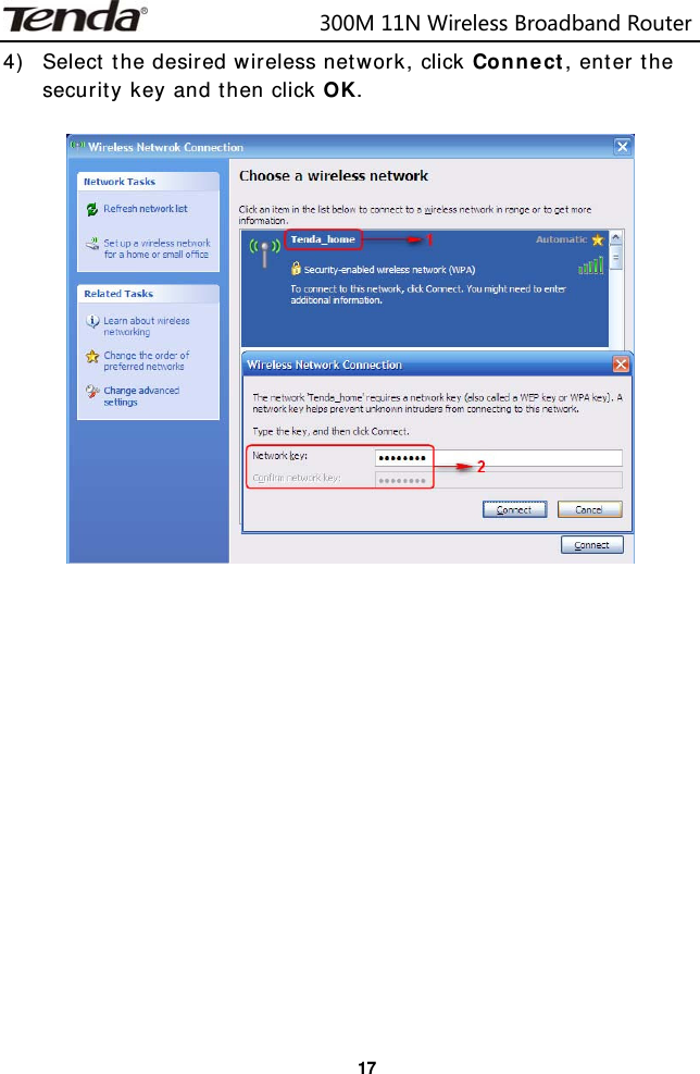
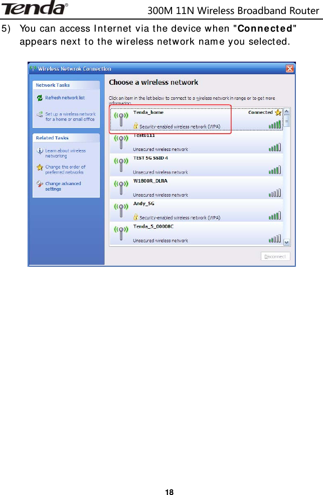
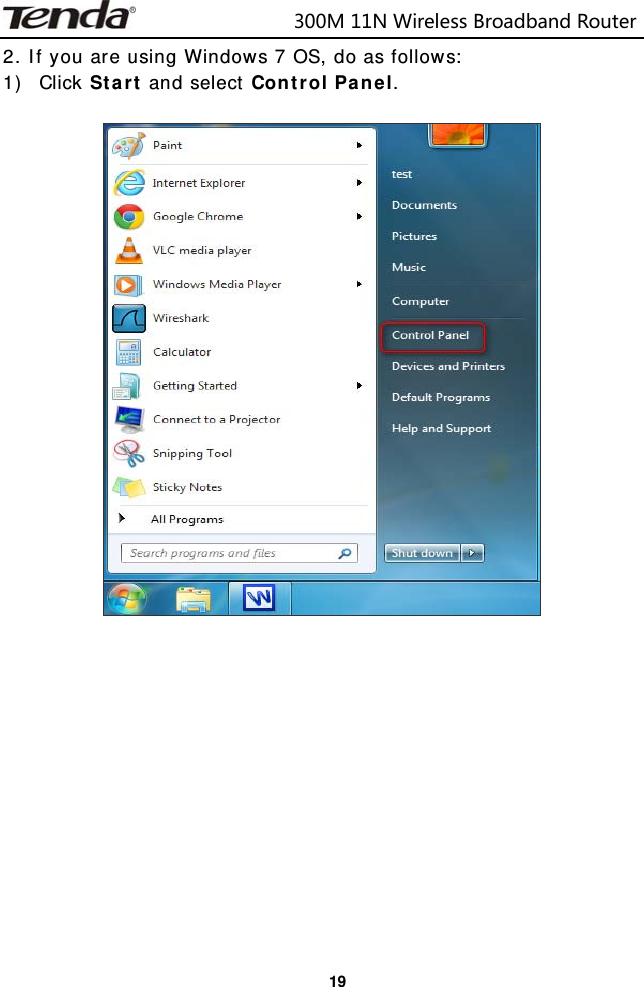
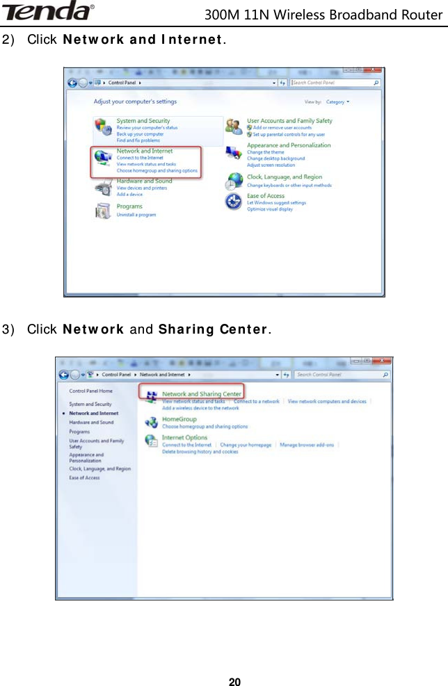
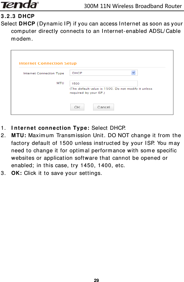
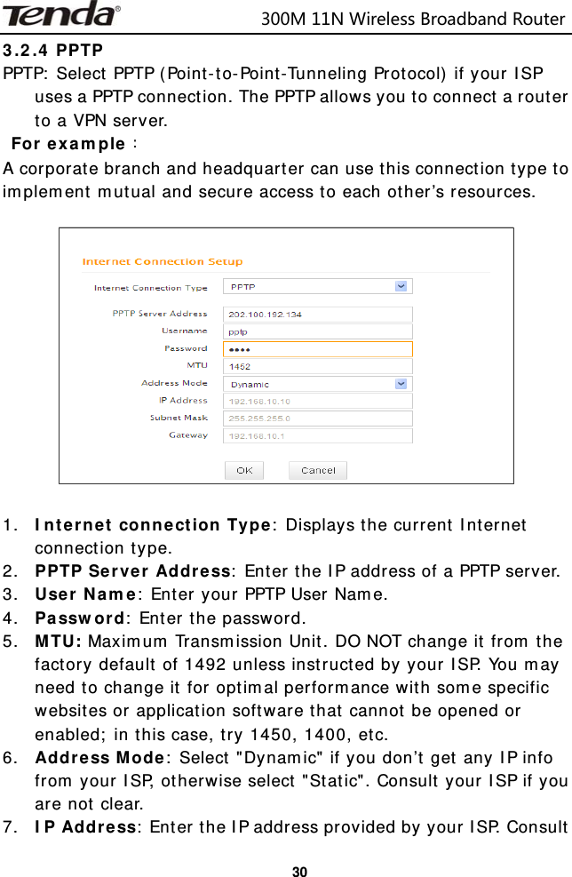
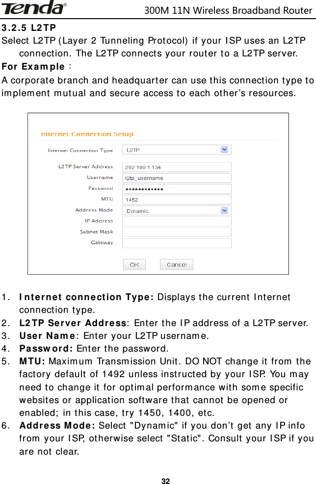
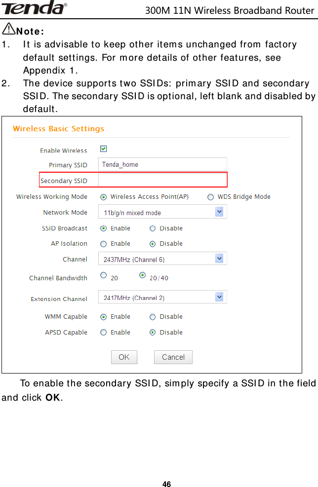
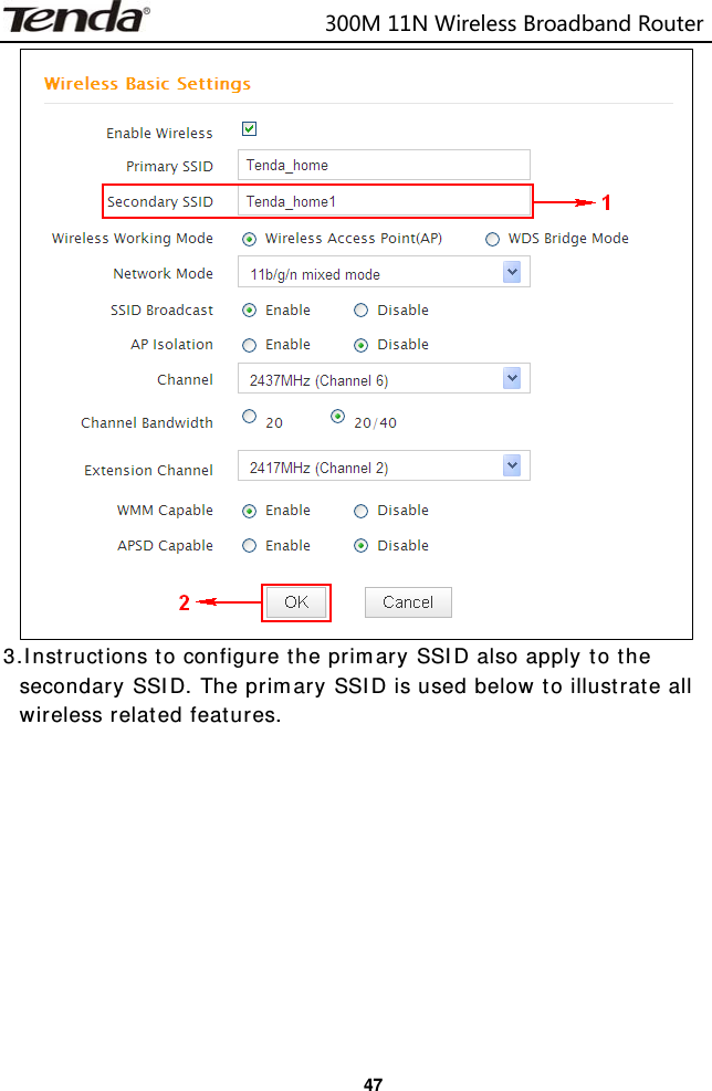
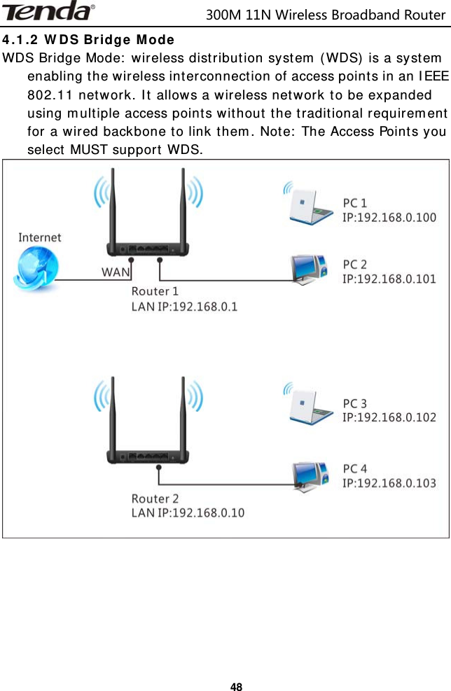
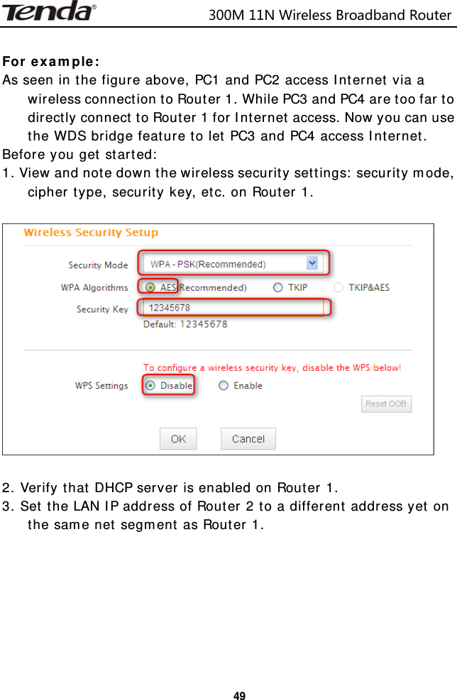
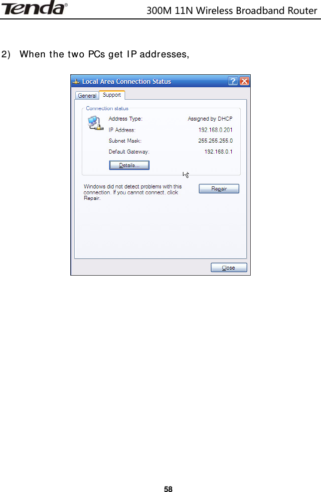
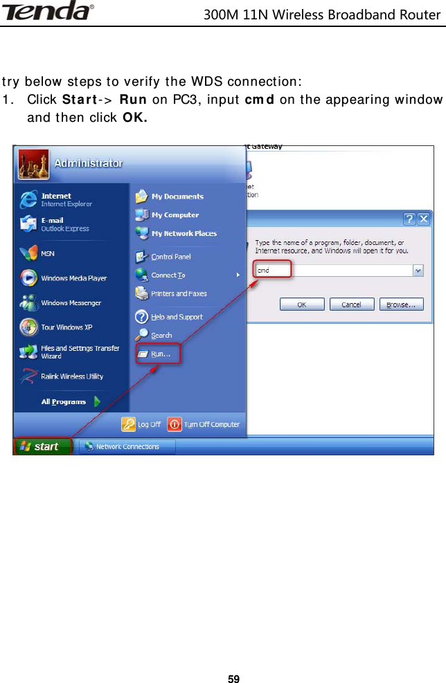
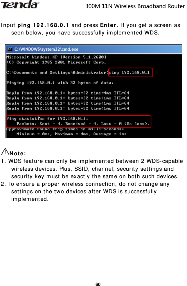
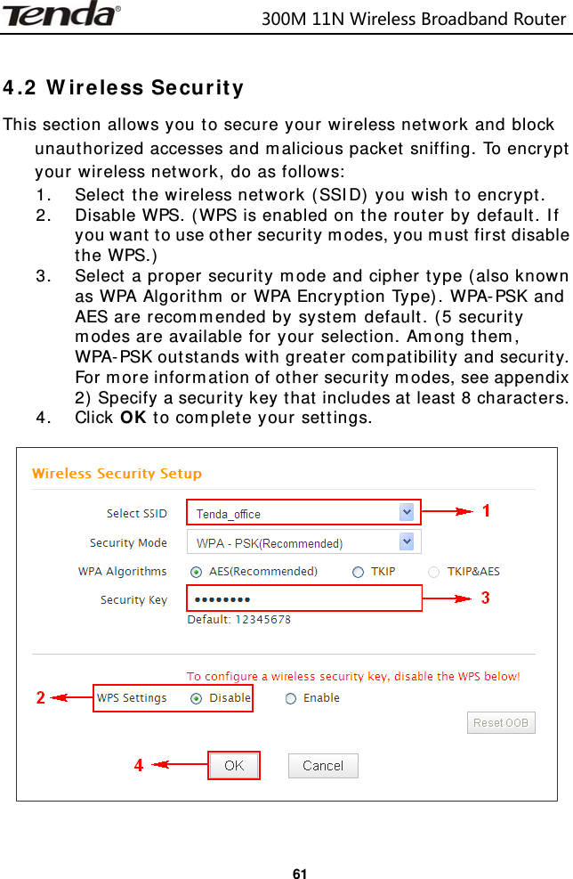
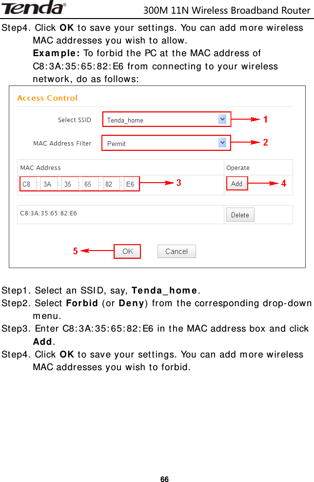
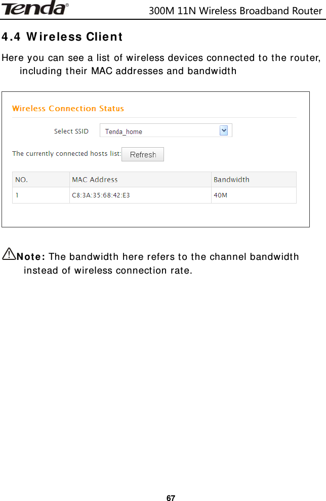
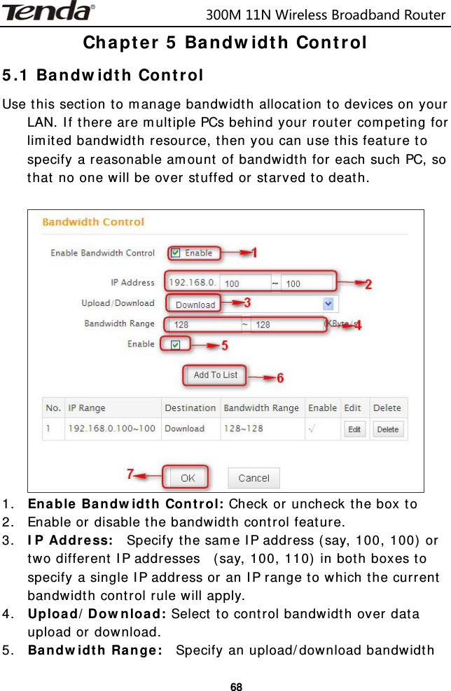
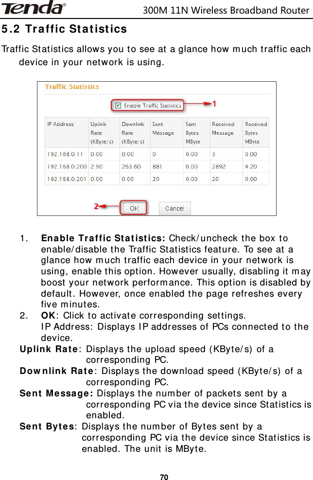
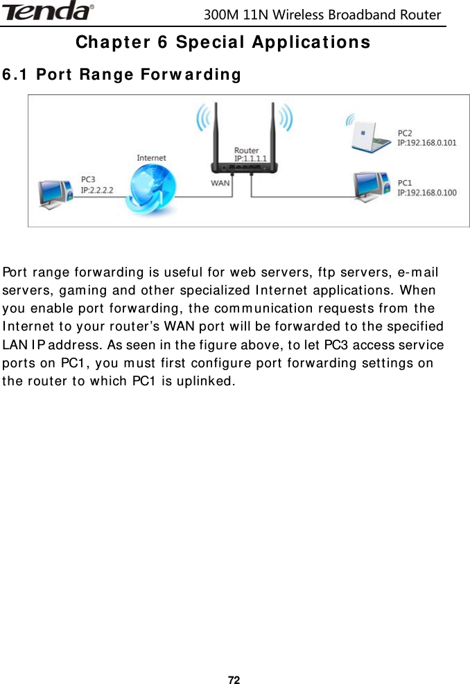
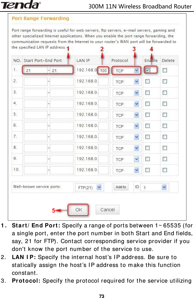
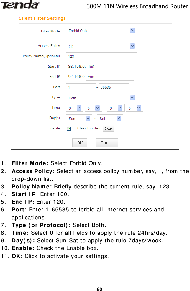
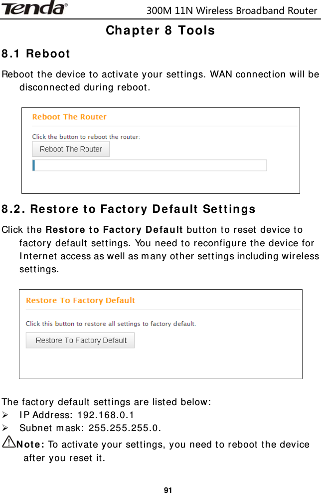
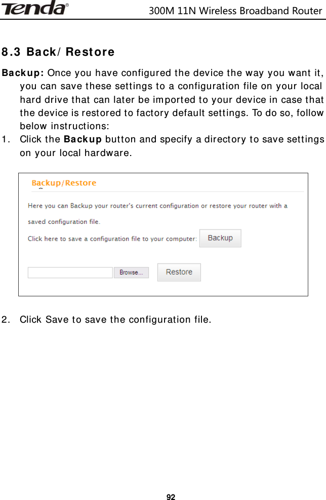
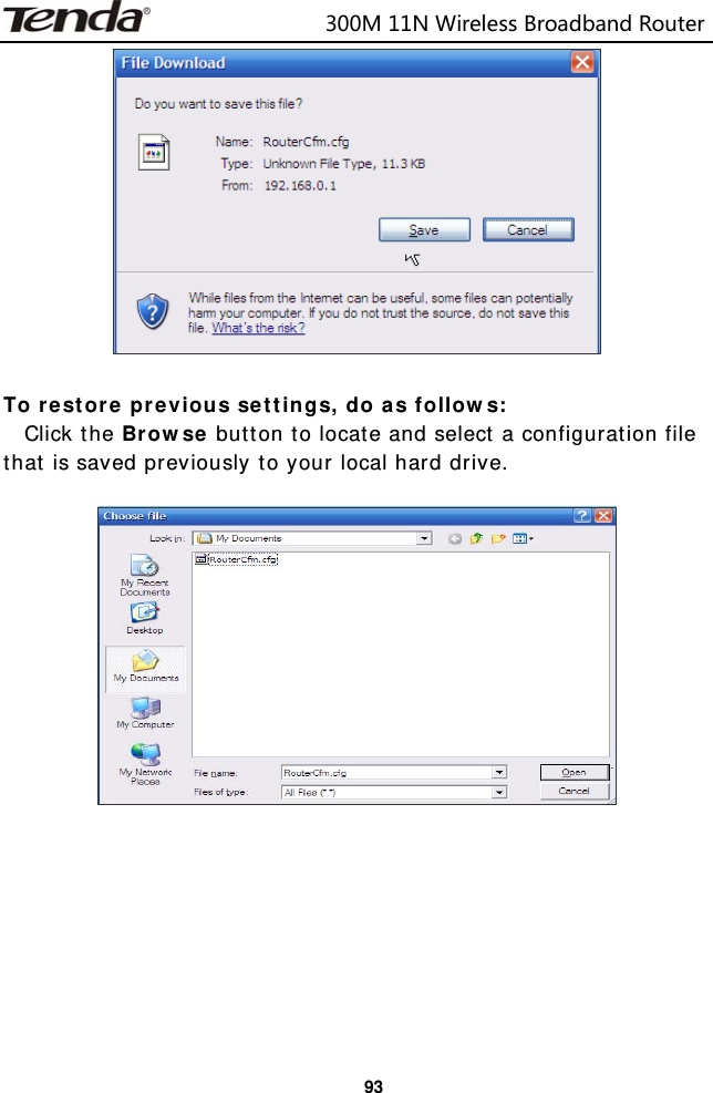
SHENZHEN TENDA TECHNOLOGY CO., LTD. 300M 11N Wireless Broadband Router

Users Manual

                        300M11NWirelessBroadbandRouter
                        300M11NWirelessBroadbandRouter   Copyright Statement is the registered trademark of Shenzhen Tenda Technology Co., Ltd. All the products and product names mentioned herein are the trademarks or registered trademarks of their respective holders. Copyright of the whole product as integration, including its accessories and software, belongs to Shenzhen Tenda Technology Co., Ltd. Without prior expressed written permission from Shenzhen Tenda Technology Co., Ltd, any individual or party is not allowed to copy, plagiarize, reproduce, or translate it into other languages. All photos and product specifications mentioned in this manual are for references only. Upgrades of software and hardware may occur; Tenda reserves the right to revise this publication and to make changes in the content hereof without obligation to notify any person or organization of such revisions or changes. If you would like to know more about our product information, please visit our website at http://www.tendacn.com.
                        300M11NWirelessBroadbandRouter  Table of Contents CHAPTER 1 PRODUCT OVERVIEW ...............................................1 1.1 WHAT IT DOES ............................................................................ 1 1.2 FEATURES ................................................................................. 1 CHAPTER 2 INSTALLATION AND QUICK SETUP GUIDE ...............3 2.1 OPEN PACKAGE ........................................................................... 3 2.2 PHYSICAL INSTALLATION ................................................................ 3 2.3 LOG IN TO WEB MANAGER .............................................................. 6 2.4 QUICK INTERNET CONNECTION SETUP ................................................ 8 2.5 VERIFY INTERNET CONNECTION SETTINGS ......................................... 10 2.6 WIRELESS SETTINGS .................................................................. 13 2.6.1 Wireless Basic Settings ................................................... 13 2.6.2 Wireless Security Settings ............................................... 14 2.7 CONNECT TO DEVICE WIRELESSLY................................................... 15 CHAPTER 3 ADVANCED SETTINGS ............................................ 24 3.1 STATUS .................................................................................. 24 3.2. INTERNET CONNECTION SETUP ..................................................... 26 3.2.1 PPPoE ........................................................................... 26 3.2.2 Static IP ........................................................................ 28 3.2.3 DHCP ............................................................................ 29 3.2.4 PPTP ............................................................................. 30 3.2.5 L2TP ............................................................................. 32 3.3 MAC CLONE ............................................................................. 34 3.4 WAN SPEED ............................................................................ 34 3.5 WAN MEDIUM TYPE ................................................................... 35 3.6 LAN SETTINGS ......................................................................... 40 3.7 DNS SETTINGS ......................................................................... 41 3.8 DHCP .................................................................................... 42 3.9 DHCP CLIENT LIST .................................................................... 42 CHAPTER 4 WIRELESS SETTINGS ............................................. 44 4.1 WIRELESS BASIC SETTINGS .......................................................... 44 4.1.1 Wireless AP Mode ........................................................... 45 4.1.2 WDS Bridge Mode .......................................................... 48 4.2 WIRELESS SECURITY .................................................................. 61 4.3 WIRELESS ACCESS CONTROL ........................................................ 65 4.4 WIRELESS CLIENT ...................................................................... 67 CHAPTER 5 BANDWIDTH CONTROL .......................................... 68 5.1 BANDWIDTH CONTROL ................................................................ 68
                        300M11NWirelessBroadbandRouter  5.2 TRAFFIC STATISTICS ................................................................... 70 CHAPTER 6 SPECIAL APPLICATIONS ........................................ 72 6.1 PORT RANGE FORWARDING ........................................................... 72 6.2 DMZ HOST ............................................................................. 75 6.3 DDNS ................................................................................... 76 6.4 UPNP .................................................................................... 78 6.5 STATIC ROUTING ....................................................................... 79 6.6 ROUTING TABLE ........................................................................ 81 CHAPTER 7 SECURITY ............................................................... 82 7.1 URL FILTER ............................................................................. 82 7.2 MAC FILTER ............................................................................ 85 7.3 CLIENT FILTER .......................................................................... 88 CHAPTER 8 TOOLS .................................................................... 91 8.1 REBOOT .................................................................................. 91 8.2. RESTORE TO FACTORY DEFAULT SETTINGS ........................................ 91 8.3 BACK/RESTORE ......................................................................... 92 8.4 SYSLOG .................................................................................. 95 8.5 REMOTE WEB-BASED MANAGEMENT ................................................. 96 8.6 TIME ..................................................................................... 97 8.7 LOGIN PASSWORD ..................................................................... 98 8.8 FIRMWARE UPGRADE .................................................................. 99 APPENDIX 1 GLOSSARY .......................................................... 100 APPENDIX 2 FAQS .................................................................. 104 APPENDIX 3 REMOVE WIRELESS NETWORK FROM YOUR PC .. 107 APPENDIX 4 SAFETY AND EMISSION STATEMENT .................. 110
                           300M11NWirelessBroadbandRouter  1Chapter 1 Product Overview 1.1 What it does Thanks for purchasing this Tenda router (collectively device or router). The device is an 802.11n compliant wireless router that delivers up to 4x faster wireless speeds and 3x farther range than 802.11g while staying backward compatible with 802.11g/b devices. Upgrading your home network to 150Mbps of Wireless N speed, the device provides an excellent solution for experiencing better wireless performance while sharing a broadband Internet connection with multiple computers over a secure wireless network. The router makes it easy to set up your wireless network in your home or office without professional installation. Thanks to the world’s most intuitive utility interface, it takes you to finish easily installing your wireless network and Internet connection in three steps. Once the setup process is complete, you can share a high-speed Internet connection, files, media, and more. Also, to prevent unauthorized access, it supports for WPA/WPA2 security standards ensure that you will be able to use the best possible encryption regardless of your other wireless devices. The router is ideal for sharing your Internet connection throughout home or small office. 1.2 Features ¾ Compliant with IEEE 802.11n, IEEE 802.11g, IEEE 802.11b, IEEE 802.3 and IEEE 802.3u standards ¾ 5dBi high gain omni-directional antenna delivers better signal and greater coverage ¾ Up to 300Mbps wireless rate; ¾ 1 10/100M WAN port for Internet connection; ¾ 4 10/100M Ethernet ports for LAN connection; ¾ Auto MDI/MDIX on each port; ¾ Provides Internet connection types: Dynamic/ static IP; can be connected to an xDSL/Cable MODEM; ¾ Combines the function of a wireless AP, router, 4-port switch and
                           300M11NWirelessBroadbandRouter  2firewall; ¾ WPA, WPA2 and WPA&WPA2 encryptions secure your wireless network against unauthorized access;   ¾ Simple and quick to secure a Wi-Fi connection at a push of the WPS button; ¾ Hidden/invisible SSID; ¾ MAC-based wireless access control; ¾ WMM streams your video and audio; ¾ SNTP to synchronize local time with Internet time servers; ¾ Supports UPnP and DDNS features; ¾ WDS support for extending existing wireless coverage; ¾ Provides virtual server and DMZ features; ¾ Provides logs to record device's usage status.
                           300M11NWirelessBroadbandRouter  3Chapter 2 Installation and Quick Setup Guide 2.1 Open package Unpack the box and verify the following items: ¾ Wireless Broadband Router ¾ Power Adapter ¾ Quick Install Guide If any of the above items is incorrect, missing, or damaged, please contact your Tenda reseller for immediate replacement. 2.2 Physical installation 1. Connect one end of the included power adapter to the device and plug the other end into a wall outlet nearby.(Using a power adapter with a different voltage rating than the one included with the device will cause damage to the device.)
                           300M11NWirelessBroadbandRouter  42. Connect one of the LAN ports on the Device to the NIC port on your PC using an Ethernet cable.     3. Connect the Ethernet cable from Internet side to the WAN port on the Device.
                           300M11NWirelessBroadbandRouter  54. Observe status of LEDs on the device and ensure that they are functioning correctly as stated in the table below.    LED Overview: LED Status Description POWER  Solid  Indicates a proper connection to the power supply SYS Blinking Indicates system is functioning improperly WAN  Solid  WAN port connected correctly Blinking WAN port is transferring data WLAN  Solid  Wireless is enabled. Blinking Transferring data LAN(1/2/3/4) Solid  LAN port connected correctly Blinking LAN port is transferring data WPS  Solid  WPS is enabled or Reset OOB is completed successfully Blinking Device is performing WPS authentication on a client device.
                           300M11NWirelessBroadbandRouter  62.3 Log in to Web Manager 1. 1). Launch a web browser; in the address bar, input 192.168.0.1 and press Enter; 2). Enter admin in the password field on the appearing login window and then click OK.
                           300M11NWirelessBroadbandRouter  7 2. Now you may access the device’s home page for quickly setting up Internet connection and wireless security.
                           300M11NWirelessBroadbandRouter  82.4 Quick Internet Connection Setup 2  common Internet connection types are available on the home page: PPPoE and DHCP. DHCP: Select DHCP (Dynamic IP) if you can access Internet as soon as your computer directly connects to an Internet-enabled ADSL/Cable modem; configure a security key (8-63 characters) to secure your wireless network and then click OK.
                           300M11NWirelessBroadbandRouter  9PPPoE: Select PPPoE (Point to Point Protocol over Ethernet) if you used to connect to the Internet using a broadband connection that requires a username and a password. Enter the user name and password provided by your ISP; configure a security key to secure your wireless network and then click OK.    Note: 1. DHCP is the default Internet connection type; 2. If you are not sure about your PPPoE username and password, contact your Internet service provider (ISP) for help. For other Internet connection types, please go to section 3.2: Internet Connection Setup.
                           300M11NWirelessBroadbandRouter  102.5 Verify Internet Connection Settings System automatically skips to the status page when you finish all needed settings on the home page. Here you can see the system status and WAN connection status of the device. 1. If you find "Connected" and a WAN IP address displayed there (as shown below), you have got a wired internet access now.
                           300M11NWirelessBroadbandRouter  11 2. If connection status displays "Disconnected" and there is no WAN IP address displayed (as seen below), connection between the Internet-enabled modem and your device may have failed. Please double check or re-connect all involved devices and cables properly and then refresh the page. If nothing is wrong, "Connecting" or "Connected" will be displayed.
                           300M11NWirelessBroadbandRouter  12 3. If "Connecting" is displayed and no WAN IP address is seen, try refreshing the page five times. And if it still displays "Connecting" try steps below: 1). Contact your ISP for assistance if you are using the DHCP connection type. 2). Read the connection diagnostic info on WAN status.    Note: Below diagnostic info will be displayed on particular occasions for your reference: 1). You have connected to Internet successfully. 2). You might have entered a wrong user name and/or a wrong password. Please contact your ISP for the correct user name and password and enter them again. 3). Ethernet cable is not connected or not properly connected to the WAN port on the device. Please reconnect it properly. 4). No response is received from your ISP. Please verify that you can
                           300M11NWirelessBroadbandRouter  13access Internet when you directly connect your PC to an Internet-enabled modem. If not, contact your local ISP for help. 2.6 Wireless Settings 2.6.1 Wireless Basic Settings If you want to create a WLAN for sharing Internet connection, simply click Wireless-> Wireless Basic Settings.  Change the SSID, you can name it whatever you like. Select 2437MHz (channel 6) and leave other options unchanged and then click OK.
                           300M11NWirelessBroadbandRouter  14 2.6.2 Wireless Security Settings If you want to encrypt your wireless network, click Wireless Security, disable WPS, specify a security key of down to 8 characters, and then click OK.
                           300M11NWirelessBroadbandRouter  152.7 Connect to Device Wirelessly Having finished above settings, you can search the device's wireless network (SSID) from your wireless devices (notebook, iPad, iPhone, etc) and enter a security key to connect to it wirelessly. 1. If you are using Windows XP OS, do as follows: 1) Click Start and select Control Panel.
                           300M11NWirelessBroadbandRouter  162) Click Network Connections.    3) Right click Wireless Network Connection and then select View Available Wireless Networks.
                           300M11NWirelessBroadbandRouter  174) Select the desired wireless network, click Connect, enter the security key and then click OK.
                           300M11NWirelessBroadbandRouter  185) You can access Internet via the device when "Connected" appears next to the wireless network name you selected.
                           300M11NWirelessBroadbandRouter  192. If you are using Windows 7 OS, do as follows: 1) Click Start and select Control Panel.
                           300M11NWirelessBroadbandRouter  202) Click Network and Internet.    3) Click Network and Sharing Center.
                           300M11NWirelessBroadbandRouter  214) Click Change adapter settings.    5) Select a desired wireless connection and click Connect/Disconnect.
                           300M11NWirelessBroadbandRouter  226)  Select the wireless network you wish to connect and click Connect.     7) Enter the security key and click OK.
                           300M11NWirelessBroadbandRouter  238) You can access Internet via the device when "Connected" appears next to the wireless network name you selected.
                           300M11NWirelessBroadbandRouter  24Chapter 3 Advanced Settings 3.1 Status Here you can see at a glance the operating status of the device.    1. Connection Status: Displays WAN connection status: Disconnected, Connecting or Connected. 2. Disconnected: Indicates that the Ethernet cable from your ISP side is not correctly connected to device's WAN port or the router is not logically connected to your ISP. 3. Connecting: Indicates that the WAN port is correctly connected and is requesting an IP address from your ISP. 4. Connected: Indicates that the router has been connected to your ISP. 5. Internet Connection Type: Displays current Internet connection type. 6. WAN IP: Displays the WAN IP address. 7. Subnet Mask: Displays WAN subnet mask provided by your ISP. 8. Gateway: Displays WAN gateway address. 9. DNS Server: Displays the preferred WAN DNS address. 10. Alternate DNS Server: Displays the alternate WAN DNS address if any.
                           300M11NWirelessBroadbandRouter  2511. Connection Time: Time duration since the device has been successfully connected to ISP.    1. LAN MAC Address: Displays device’s LAN MAC address. 2. WAN MAC Address: Displays device’s WAN MAC address. 3. System Time: Displays device’s system time either customized or obtained from Internet. 4. Up Time: Displays device's uptime. 5. Connected Client(s): Displays the number of connected network devices (which obtain IP addresses from device DHCP server). 6. Firmware Version: Displays Device’s current firmware version. 7. Hardware Version: Displays Device’s current hardware version.
                           300M11NWirelessBroadbandRouter  263.2. Internet Connection Setup 3.2.1 PPPoE Select PPPoE (Point to Point Protocol over Ethernet) if you used to connect to the Internet using a broadband connection that requires a username and a password and enter the user name and password provided by your ISP.
                           300M11NWirelessBroadbandRouter  271. Internet connection Type: Select PPPoE.   2. PPPoE User Name: Enter the User Name provided by your ISP.  3. PPPoE Password: Enter the password provided by your ISP. 4. MTU: Maximum Transmission Unit. DO NOT change it from the factory default of 1492 unless necessary. You may need to change it for optimal performance with some specific websites or application software that cannot be opened or enabled; in this case, try 1450, 1400, etc. 5. Service Name: Description of PPPoE connection. Leave blank unless otherwise required. 6.  Server Name: Description of server. Leave blank unless otherwise required. 7.  Connect Automatically: Connect automatically to the Internet after rebooting the system or connection failure. Connect Manually: Require the user to manually connect to the Internet before each session. Connect On Demand: Re-establish connection to the Internet only when there is data transmission. Connect During Specified Time Period: Only connect to Internet during a specified time period. 8.  OK: Click it to save all your settings.
                           300M11NWirelessBroadbandRouter  283.2.2 Static IP Select Static IP if your ISP provides all the needed info. You will need to enter the provided IP address, subnet mask, gateway address, and DNS address(es) in corresponding fields.     1. Internet connection Type: Select Static IP. 2. IP Address: Enter the IP address provided by your ISP. Consult your ISP if you are not clear. 3. Subnet mask: Enter the subnet mask provided by your ISP. 4.  Gateway: Enter the WAN Gateway provided by your ISP. Consult your ISP if you are not clear. 5. DNS Server: Enter the DNS address provided by your ISP. 6. Alternate DNS Server: Enter the other DNS address if your ISP provides 2 such addresses (optional). 7. OK: Click it to save all your settings.
                           300M11NWirelessBroadbandRouter  293.2.3 DHCP Select DHCP (Dynamic IP) if you can access Internet as soon as your computer directly connects to an Internet-enabled ADSL/Cable modem.     1. Internet connection Type: Select DHCP. 2. MTU: Maximum Transmission Unit. DO NOT change it from the factory default of 1500 unless instructed by your ISP. You may need to change it for optimal performance with some specific websites or application software that cannot be opened or enabled; in this case, try 1450, 1400, etc. 3. OK: Click it to save your settings.
                           300M11NWirelessBroadbandRouter  303.2.4 PPTP  PPTP: Select PPTP (Point-to-Point-Tunneling Protocol) if your ISP uses a PPTP connection. The PPTP allows you to connect a router to a VPN server.  For example: A corporate branch and headquarter can use this connection type to implement mutual and secure access to each other’s resources.    1. Internet connection Type: Displays the current Internet connection type. 2. PPTP Server Address: Enter the IP address of a PPTP server. 3. User Name: Enter your PPTP User Name. 4. Password: Enter the password. 5. MTU: Maximum Transmission Unit. DO NOT change it from the factory default of 1492 unless instructed by your ISP. You may need to change it for optimal performance with some specific websites or application software that cannot be opened or enabled; in this case, try 1450, 1400, etc. 6. Address Mode: Select "Dynamic" if you don’t get any IP info from your ISP, otherwise select "Static". Consult your ISP if you are not clear. 7. IP Address: Enter the IP address provided by your ISP. Consult
                           300M11NWirelessBroadbandRouter  31your ISP if you are not clear. 8. Subnet mask: Enter the subnet mask provided by your ISP. 9. Gateway: Enter the WAN Gateway provided by your ISP. Consult your ISP if you are not clear.
                           300M11NWirelessBroadbandRouter  323.2.5 L2TP  Select L2TP (Layer 2 Tunneling Protocol) if your ISP uses an L2TP connection. The L2TP connects your router to a L2TP server.  For Example:  A corporate branch and headquarter can use this connection type to implement mutual and secure access to each other’s resources.    1. Internet connection Type: Displays the current Internet connection type. 2. L2TP Server Address: Enter the IP address of a L2TP server. 3. User Name: Enter your L2TP username. 4. Password: Enter the password. 5. MTU: Maximum Transmission Unit. DO NOT change it from the factory default of 1492 unless instructed by your ISP. You may need to change it for optimal performance with some specific websites or application software that cannot be opened or enabled; in this case, try 1450, 1400, etc. 6. Address Mode: Select "Dynamic" if you don’t get any IP info from your ISP, otherwise select "Static". Consult your ISP if you are not clear.
                           300M11NWirelessBroadbandRouter  337. IP Address: Enter the IP address provided by your ISP. Consult your ISP if you are not clear. 8. Subnet mask: Enter the subnet mask provided by your ISP. 9. Gateway: Enter the WAN Gateway provided by your ISP. Consult your ISP if you are not clear.  Note:  1. PPPOE, PPTP and L2TP cannot be used simultaneously!  2. For PPTP and L2TP Internet connections, only Static IP or Dynamic IP is available. 3. Note that PPTP and L2TP may not be available on some products.
                           300M11NWirelessBroadbandRouter  34 3.3 MAC Clone This section allows you to configure Device’s WAN MAC address.    1. MAC Address: Config device’s WAN MAC address. 2. Clone MAC Address: Click to copy your PC's MAC address to the device as a new WAN MAC address. 3. Restore Default MAC: Reset device’s WAN MAC to factory default.  3.4 WAN Speed Here you can set the speed and duplex mode for WAN port. It is advisable to keep the default Auto setting to get the best speed.
                           300M11NWirelessBroadbandRouter  353.5 WAN Medium Type The device supports two WAN medium types: wired and wireless. Select Wired WAN if you need to connect to your ISP via an Ethernet cable or select Wireless WAN if you directly connect to your WISP wirelessly. The default WAN Medium Type is Wired WAN, so no settings are required here if you connect to your ISP via an Ethernet cable. If you connect to your WISP wirelessly, do as follows: 1. Select Wireless WAN and enable the scan feature.
                           300M11NWirelessBroadbandRouter  36 2. Select the wireless network you wish to connect, say, Tenda_office, and click OK. Then close scan.     3.  1). Verify that SSID and channel on this page are exactly the same as they are on the uplink wireless network you just selected.  2). Configure the same security mode, security key, cipher type (or WPA Algorithm) as they are on the uplink wireless network you just selected. Click OK.
                           300M11NWirelessBroadbandRouter  37   1. WAN Medium Type: Select the WAN medium type you are going to use. 2. Open Scan (or Scan): Click to search for available wireless networks in the area and select the one you wish to connect. 3. SSID: The wireless network name of the uplink wireless device. 4. Channel: The channel used by the uplink wireless device. 5. Security Mode: The security mode used by the uplink wireless device. 6. WPA Algorithms (or Cipher Type): The WPA Algorithm (or Cipher Type) used by the uplink wireless device. 7. Key (or Security Key): The security key used by the uplink wireless device. 8. OK: Click this button and the router will restart to save your settings.
                           300M11NWirelessBroadbandRouter  38Note: If you change the device’s LAN IP address, you must use the new one to log on to the web-based configuration utility.  For example: If SSID, security mode, cipher type (WPA Algorithm), security key and channel your WISP AP are respectively Myhome, WPA2-PSK,AES, Tenda_router and 11, then simply enter them in corresponding fields as seen below.
                           300M11NWirelessBroadbandRouter  39Or you can use the Open Scan (or Scan) option to have the SSID and channel of the uplink wireless device automatically copied to this page. When you finish all these settings, go to Advanced-> Internet Connection Setup and select a proper Internet connection type (If your ISP is using a DHCP connection, simply select DHCP).
                           300M11NWirelessBroadbandRouter  403.6 LAN Settings Click Advanced -> LAN Settings to enter the screen below.    1. LAN MAC Address: Displays device's LAN MAC address, which is NOT changeable. 2. IP Address: Device's LAN IP address. The default is 192.168.0.1. You can change it according to your need. 3. Subnet Mask: Device’s LAN subnet mask, 255.255.255.0 by default. 4. OK: Click to save your settings.
                           300M11NWirelessBroadbandRouter  413.7 DNS Settings DNS is short for Domain Name System or Domain Name Service.     1. Enable Manual DNS Assignment: Check to activate DNS settings. 2. Primary DNS Server:Enter the primary DNS address provided by your IPS. 3. Alternate DNS Server:Enter the other DNS address if your ISP provides 2 such addresses (optional). 4. OK: Click to save your settings. Note: 1. Web pages are not able to open if DNS server addresses are entered incorrectly.  2. Do remember to restart the device to activate new settings when you finish all settings.
                           300M11NWirelessBroadbandRouter  423.8 DHCP The Dynamic Host Configuration Protocol (DHCP) is an automatic configuration protocol used on IP networks. If you enable the built-in DHCP server on the device, it will automatically configure the TCP/IP settings for all your LAN computers (including IP address, subnet mask, gateway and DNS etc), eliminating the need of manual intervention. Just be sure to set all computers on your LAN to be DHCP clients by selecting "Obtain an IP Address Automatically" respectively on each such PC. When turned on, these PCs will automatically load IP information from the DHCP server. (This feature is enabled by default. Do NOT disable it unless necessary)        3.9 DHCP Client List DHCP Client List displays information of devices that have obtained IP addresses from the device’s DHCP Server. If you would like some devices on your network to always get the same IP addresses, you can manually add a static DHCP reservation entry
                           300M11NWirelessBroadbandRouter  43for each such device.    1. IP Address: Enter the IP address for static DHCP reservation. 2. MAC Address: Enter the MAC address of a computer to always receive the same IP address (the IP you just specified). 3. Add: Click to add the entry to the MAC address reservation list. 4. OK: Click to save your settings. Note: If the IP address you have reserved for your PC is currently used by another client, then you will not be able to obtain a new IP address from the device's DHCP server, instead, you must manually specify a different IP address for your PC to access Internet.
                           300M11NWirelessBroadbandRouter  44Chapter 4 Wireless Settings 4.1 Wireless Basic Settings Here you can expand your wireless coverage with the following modes: Wireless AP (default mode) and WDS.  1. Wireless Access Point (AP): Select this mode if you want to convert an existing wired network to a wireless network so as to extend Internet access to wireless clients. 2. WDS Bridge Mode: wireless distribution system (WDS) is a system enabling the wireless interconnection of access points in an IEEE 802.11 network. It allows a wireless network to be expanded using multiple access points without the traditional requirement for a wired backbone to link them. Select this mode if you want to extend an existing wireless network. The two modes are described as below:
                           300M11NWirelessBroadbandRouter  454.1.1 Wireless AP Mode        1. SSID: This is the public name of your wireless network. The default is Tenda_XXXXXX. XXXXXX is the last six characters in the device's MAC address. It is recommended that you change it for better security and identification. 2. Channel: Select a channel that is the least used by neighboring networks from the drop-down list or Auto. Channels 1, 6 and 11 are recommended. 3. OK: Click to save your settings.
                           300M11NWirelessBroadbandRouter  46Note: 1. It is advisable to keep other items unchanged from factory default settings. For more details of other features, see Appendix 1. 2. The device supports two SSIDs: primary SSID and secondary SSID. The secondary SSID is optional, left blank and disabled by default.  To enable the secondary SSID, simply specify a SSID in the field and click OK.
                           300M11NWirelessBroadbandRouter  47 3.Instructions to configure the primary SSID also apply to the secondary SSID. The primary SSID is used below to illustrate all wireless related features.
                           300M11NWirelessBroadbandRouter  484.1.2 WDS Bridge Mode WDS Bridge Mode: wireless distribution system (WDS) is a system enabling the wireless interconnection of access points in an IEEE 802.11 network. It allows a wireless network to be expanded using multiple access points without the traditional requirement for a wired backbone to link them. Note: The Access Points you select MUST support WDS.
                           300M11NWirelessBroadbandRouter  49 For example: As seen in the figure above, PC1 and PC2 access Internet via a wireless connection to Router 1. While PC3 and PC4 are too far to directly connect to Router 1 for Internet access. Now you can use the WDS bridge feature to let PC3 and PC4 access Internet. Before you get started: 1. View and note down the wireless security settings: security mode, cipher type, security key, etc. on Router 1.    2. Verify that DHCP server is enabled on Router 1. 3. Set the LAN IP address of Router 2 to a different address yet on the same net segment as Router 1.
                           300M11NWirelessBroadbandRouter  50 As shown below: Router 1:  LAN IP: 192.168.0.1; Subnet Mask: 255.255.255.0; Router 2:  LAN IP:192.168.0.10; Subnet Mask: 255.255.255.0;
                           300M11NWirelessBroadbandRouter  51Then do as follows: 1. Configure Router 2: 1) Wireless Working Mode: Select WDS Bridge Mode. 2) Click Open Scan (or Scan) to search for Router 1.
                           300M11NWirelessBroadbandRouter  52  3) Select the wireless network to connect and click OK.
                           300M11NWirelessBroadbandRouter  534) Verify that the SSID, channel, and AP MAC address on the page match those of the added wireless network. If not, manually correct them.
                           300M11NWirelessBroadbandRouter  54 5) Close Scan and click OK to save your settings.
                           300M11NWirelessBroadbandRouter  556) Go to Wireless Security page and set the wireless security settings exactly as they are on the link partner (Router 1).  7) Go to DHCP Server to disable the DHCP on Router 2. Now you have finished all settings on Router 2 required for WDS.  2. Configure Router 1: 1) Go to wireless section on Router 1 and specify WDS (or WDS Bridge) as its wireless working mode. 2) Manually enter Router 2's MAC address (Also, you can use the Scan option as mentioned above) and click OK to finish your settings.
                           300M11NWirelessBroadbandRouter  56
                           300M11NWirelessBroadbandRouter  57 3. Configure PC3 and PC4: 1) Set PC3 and PC4 to Obtain an IP address automatically.
                           300M11NWirelessBroadbandRouter  58  2) When the two PCs get IP addresses,
                           300M11NWirelessBroadbandRouter  59  try below steps to verify the WDS connection: 1. Click Start-> Run on PC3, input cmd on the appearing window and then click OK.
                           300M11NWirelessBroadbandRouter  60 Input ping 192.168.0.1 and press Enter. If you get a screen as seen below, you have successfully implemented WDS.    Note:  1. WDS feature can only be implemented between 2 WDS-capable wireless devices. Plus, SSID, channel, security settings and security key must be exactly the same on both such devices. 2. To ensure a proper wireless connection, do not change any settings on the two devices after WDS is successfully implemented.
                           300M11NWirelessBroadbandRouter  61 4.2 Wireless Security This section allows you to secure your wireless network and block unauthorized accesses and malicious packet sniffing. To encrypt your wireless network, do as follows: 1. Select the wireless network (SSID) you wish to encrypt. 2. Disable WPS. (WPS is enabled on the router by default. If you want to use other security modes, you must first disable the WPS.) 3. Select a proper security mode and cipher type (also known as WPA Algorithm or WPA Encryption Type). WPA-PSK and AES are recommended by system default. (5 security modes are available for your selection. Among them, WPA-PSK outstands with greater compatibility and security. For more information of other security modes, see appendix 2) Specify a security key that includes at least 8 characters. 4. Click OK to complete your settings.
                           300M11NWirelessBroadbandRouter  62 WPS Wi-Fi Protected Setup makes it easy for home users who know little of wireless security to establish a home network, as well as to add new devices to an existing network without entering long passphrases or configuring complicated settings. Simply enter a PIN code or press the software PBC button or hardware WPS button (if any) and a secure wireless connection is established.  Operation Instructions: PBC: To use WPS-PBC, try two ways below: 1) Press the hardware WPS button on the router for about 1 second and then enable WPS/PBC on the client device within 2 minutes; 2) Press the hardware WPS button on the router for about 1 second and then enable WPS/PBC on the client device within 2 minutes;
                           300M11NWirelessBroadbandRouter  63 PIN: On the wireless security page, enable WPS, select PIN and enter the 8-digit PIN code from network adapter; then, within 2 minutes, enable WPS/PIN on the client device;    Note: 1. With WPS successfully enabled, the WPS LED on the router keeps blinking for about 2 minutes, and during this time, you can enable WPS on a wireless adapter; if the adapter successfully joins the wireless network, the WPS LED will display a solid light. Repeat steps above if you want to add more wireless adapters to the router. 2. Reset OOB: Clicking this button will reset SSID to factory default and disable security mode. 3. Existing wireless settings will still be maintained by default after a successful WPS connection. Namely security settings and SSID on the router will still be the same. If you want to generate a random wireless key via WPS, click Reset OOB and then follow WPS setup instructions above.
                           300M11NWirelessBroadbandRouter  64     Note:  1. To use the WPS security, the wireless client must be also WPS-capable. 2. Before you press the hardware WPS button on the device for WPS/PBC connection, making sure the WPS feature has been enabled on the device.
                           300M11NWirelessBroadbandRouter  65 4.3 Wireless Access Control The Access Control feature allows you to specify a list of devices to Permit (Allow) or Forbid (Deny) a connection to your wireless network via the devices’ MAC addresses. All other devices not listed as Permitted will be Forbidden and vice versa. 1. Select the wireless network (SSID) you wish to enable Access Control on. 2. MAC Address Filter: Select Permit or Forbid from the drop-down list.    3. To permit a wireless device to connect to your wireless network, select Permit (or Allow), enter its MAC address, click Add and then OK. Then only this device listed as “Permitted” will be able to connect to your wireless network; all other wireless devices will forbidden.   Step1. Select the wireless network (SSID) you wish to enable Access Control on. Step2. Select Permit (or Allow) from the corresponding drop-down menu. Step3. Enter the MAC address you wish to permit in the MAC address box and click Add.
                           300M11NWirelessBroadbandRouter  66Step4. Click OK to save your settings. You can add more wireless MAC addresses you wish to allow.  Example: To forbid the PC at the MAC address of C8:3A:35:65:82:E6 from connecting to your wireless network, do as follows:   Step1. Select an SSID, say, Tenda_home. Step2. Select Forbid (or Deny) from the corresponding drop-down menu. Step3. Enter C8:3A:35:65:82:E6 in the MAC address box and click Add. Step4. Click OK to save your settings. You can add more wireless MAC addresses you wish to forbid.
                           300M11NWirelessBroadbandRouter  674.4 Wireless Client Here you can see a list of wireless devices connected to the router, including their MAC addresses and bandwidth    Note: The bandwidth here refers to the channel bandwidth instead of wireless connection rate.
                           300M11NWirelessBroadbandRouter  68Chapter 5 Bandwidth Control 5.1 Bandwidth Control Use this section to manage bandwidth allocation to devices on your LAN. If there are multiple PCs behind your router competing for limited bandwidth resource, then you can use this feature to specify a reasonable amount of bandwidth for each such PC, so that no one will be over stuffed or starved to death.   1. Enable Bandwidth Control: Check or uncheck the box to  2. Enable or disable the bandwidth control feature. 3. IP Address:  Specify the same IP address (say, 100, 100) or two different IP addresses  (say, 100, 110) in both boxes to specify a single IP address or an IP range to which the current bandwidth control rule will apply. 4. Upload/Download: Select to control bandwidth over data upload or download. 5. Bandwidth Range:  Specify an upload/download bandwidth
                           300M11NWirelessBroadbandRouter  69range limit on specified PC(s). The unit is KByte/s. 1M=128KByte/s. Note that maximum upload/download bandwidth should not exceed your router's WAN bandwidth limit. (Consult your ISP if you are not clear.). 6. Enable: Check to enable current rule. (When disabled, corresponding entry will not take effect though existing in fact.) 7. Add to List: Click to add current rule to the rule list. 8. OK: Click to activate your settings. For example: If you are sharing a 4M broadband connection with a neighbor, who always exhausts the bandwidth resource downloading data, this feature will help. Simply specify half of the 4M bandwidth for your neighbor's PC (say,    192.168.0.100) and you will no longer need to struggle for bandwidth and your neighbor will only get up to 2M bandwidth. To do so, follow instructions below: 11.. CChheecckk  EEnnaabbllee..  22. Input "192.168.0.100" in both IP address boxes. 33..  Select Download. 44..  Enter "256" in both bandwidth range fields. 55..  Check Enable. 66..  Click Add To List 77..  Click OK.
                           300M11NWirelessBroadbandRouter  705.2 Traffic Statistics Traffic Statistics allows you to see at a glance how much traffic each device in your network is using.     1. Enable Traffic Statistics: Check/uncheck the box to enable/disable the Traffic Statistics feature. To see at a glance how much traffic each device in your network is using, enable this option. However usually, disabling it may boost your network performance. This option is disabled by default. However, once enabled the page refreshes every five minutes. 2. OK: Click to activate corresponding settings. IP Address: Displays IP addresses of PCs connected to the device. Uplink Rate: Displays the upload speed (KByte/s) of a corresponding PC. Downlink Rate: Displays the download speed (KByte/s) of a corresponding PC. Sent Message: Displays the number of packets sent by a corresponding PC via the device since Statistics is enabled. Sent Bytes: Displays the number of Bytes sent by a corresponding PC via the device since Statistics is enabled. The unit is MByte.
                           300M11NWirelessBroadbandRouter  71Received Message: Displays the number of packets received by a corresponding PC via the device since Statistics is enabled. Received Bytes: Displays the number of Bytes received by a corresponding PC via the device since Statistics is enabled. The unit is MByte.
                           300M11NWirelessBroadbandRouter  72Chapter 6 Special Applications  6.1 Port Range Forwarding    Port range forwarding is useful for web servers, ftp servers, e-mail servers, gaming and other specialized Internet applications. When you enable port forwarding, the communication requests from the Internet to your router’s WAN port will be forwarded to the specified LAN IP address. As seen in the figure above, to let PC3 access service ports on PC1, you must first configure port forwarding settings on the router to which PC1 is uplinked.
                           300M11NWirelessBroadbandRouter  73 1. Start/End Port: Specify a range of ports between 1~65535 (for a single port, enter the port number in both Start and End fields, say, 21 for FTP). Contact corresponding service provider if you don't know the port number of the service to use. 2. LAN IP: Specify the internal host’s IP address. Be sure to statically assign the host’s IP address to make this function constant. 3. Protocol: Specify the protocol required for the service utilizing
                           300M11NWirelessBroadbandRouter  74the port(s). 4. Enable: Check to enable current settings. 5. OK: Click to activate your settings. Now, your friends only need to enter ftp://xxx.xxx.xxx.xxx:21 in their browsers to access your FTP server xxx.xxx.xxx.xxx is the router's WAN IP address. Assuming it is 172.16.102.89, and then your friends need to enter ftp://172.16.102.89:21 in their browsers.  For example: You want to share some large files with your friends who are not in your LAN; however it is not convenient to transfer such large files across network. Then, you can set up your own PC as a FTP server and use the Port (Range) Forwarding feature to let your friends access these files. Assuming that the static IP address of the FTP server (Namely, your PC) is 192.168.0.10, you want your friends to access this FTP server through default port of 21 using the TCP protocol, then do as follows: 1. Start/End Port: Enter 21 in both Start Port and End Port fields. 2. LAN IP: Enter 192.168.0.10 3. Protocol: Select TCP. 4. Enable: Check to enable current settings. 5. OK: Click to activate your settings.  Note: If you include port 80 on this section, you must set the port for remote (web-based) management to a different number than 80, such as 8080, otherwise the virtual server feature may not take effect.
                           300M11NWirelessBroadbandRouter  75  6.2 DMZ Host The DMZ (De-Militarized Zone) function disables the firewall on the router for one device for a special purpose service such as Internet gaming or video conferencing. Enabling DMZ host may expose your local network to potential attacks. So it is advisable to use it with caution.     1. DMZ Host IP Address: The IP Address of the device for which the router’s firewall will be disabled. Be sure to statically set the IP Address of that device for this function to be consistent. 2. Enable: Check/uncheck to enable/disable the DMZ host feature. 3. OK: Click to enable your settings. Note: Once enabled, the DMZ host loses protection from device's firewall and becomes vulnerable to attacks.
                           300M11NWirelessBroadbandRouter  76 6.3 DDNS Dynamic DNS or DDNS is a term used for the updating in real time of Internet Domain Name System (DNS) name servers. Dynamic DNS or DDNS is a term used for the updating in real time of Internet Domain Name System (DNS) name servers. We use a numeric IP address allocated by Internet Service Provider (ISP) to connect to Internet; the address may either be stable ("static"), or may change from one session on the Internet to the next ("dynamic"). However, a numeric address is inconvenient to remember; an address which changes unpredictably makes connection impossible. The DDNS provider allocates a static host name to the user; whenever the user is allocated a new IP address this is communicated to the DDNS provider by software running on a computer or network device at that address; the provider distributes the association between the host name and the address to the Internet's DNS servers so that they may resolve DNS queries. Thus, uninterrupted access to devices and services whose numeric IP address may change is maintained. (You need to have an account with one of the Service Providers in the drop-down menu first.)
                           300M11NWirelessBroadbandRouter  77    1. DDNS Service: Select to enable/disable the DDNS feature. 2. Service Provider: Select your DDNS service provider from the drop-down menu. (Here you can see a list of available service providers. Note that service providers not listed here are not available for use.) 3. User Name: Enter the registered user name. 4. Password: Enter the registered password. 5. Domain Name: Enter the domain name you register, say, tenda.dyndns.org. 6. OK: Click to activate your settings. Note:     This feature is usually used together with virtual server. Configure necessary settings on port forwarding interface and enter the information provided by your DDNS service provider on the DDNS screen. Others can access your web server by simply entering http://tenda.dyndns.org in their browser address bar.
                           300M11NWirelessBroadbandRouter  78 6.4 UPNP The Universal Plug and Play (UPnP) feature allows network devices, such as computers from Internet, to access resources on local host or devices as needed. UPnP-enabled devices can be discovered automatically by the UPnP service application on the LAN. This feature is enabled by default. No settings are required.    Enable UPnP: Check/uncheck to enable/disable the UPnP feature. OK: Click to complete your settings.
                           300M11NWirelessBroadbandRouter  79 6.5 Static Routing When there are several routers in the network, you may want to set up static routing. Static routing determines the path of the data in your network. You can use this feature to allow users on different IP domains to access the Internet via this device. It is not recommended to use this setting unless you are familiar with static routing. In most cases, dynamic routing is recommended, because this feature allows the router to detect the physical changes of the network layout automatically. If you want to use static routing, make sure the router’s DHCP function is disabled.    1. Destination Network IP Address: Specify a single IP address, say, 172.17.0.100, or an IP net segment, .say, 192.168.88.0. 2. Subnet Mask: Specify a Subnet Mask that corresponds to the specified destination IP. 3. Gateway: Specif the IP address for next hop. 4. OK: Click to activate your settings.
                           300M11NWirelessBroadbandRouter  80  Note:  1. Gateway must be on the same IP net segment as device's LAN/WAN IP address. 2. Subnet Mask must be entered 255.255.255.255 if destination IP address is a host. 3. Subnet Mask must be entered accordingly if destination IP address represents an IP network segment. It must correspond to the specified IP address. For example, for IP address of 10.0.0.0, you may enter a subnet mask of 255.0.0.0.
                           300M11NWirelessBroadbandRouter  81 6.6 Routing Table This page displays the device core routing table which lists destination IP, subnet mask, gateway, hop count and interface.    The principal task for a router is to look for an optimal transfer path for each data packet passing through it, and transfer it to the specified destination. To complete this work, the router stores and maintains related data of various transfer paths, i.e. establishing a routing table, for future route selection.
                           300M11NWirelessBroadbandRouter  82Chapter 7 Security 7.1 URL Filter To better control LAN PCs, you can use the URL filter functionality to allow or disallow such PCs to access certain websites within a specified time range.     1. Filter Mode: Select a proper filter mode, say, Forbid Only (or Forbid/Deny). 2. Access Policy:  Select an access policy number, say, 1, from the drop-down list. 3. Policy Name: Briefly describe the current rule, say, youtube, (It can only consist of numbers, letters, or underscore).
                           300M11NWirelessBroadbandRouter  834. Start IP/End IP: Enter the same IP address or 2 different IP addresses in both boxes to specify a single PC or a range of PCs for the current rule to apply to. 5. URL Character String: Enter the domain name you wish to filter out, say, youtube. 6. Time: Specify a time period for a current rule to take effect. If the field is set to 0:00-0:00, the rule will be applied 24hrs/day. 7. Day(s): Select a day or several days for a current rule to take effect. If Sun-Sat is selected, the rule will apply 7days/week. 8. Enable: Check/uncheck to enable/disable the feature. 9. OK: Click to activate your settings. Example: If you want to disallow all computers on your LAN to access youtube.com from 8:00 to 18:00 during working days: Monday- Friday, then do as follows:
                           300M11NWirelessBroadbandRouter  84    1. Filter Mode: Select Forbid Only. 2. Access Policy: Select an access policy number, say, 1, from the drop-down list. 3. Policy Name: Briefly describe the current rule, say, youtube, (It can only consist of numbers, letters, or underscore). 4. Start IP/End IP: Enter 2-254. 5. URL Character String: Enter youtube. 6. Time: Select 8:00-18:00.Day(s): Select Monday to Friday.   7. Enable: Check the Enable box.  8. OK: Click to save your settings. Note: Each rule can only include one domain name. Simply add more rules accordingly, if you want to filter multiple domain names.
                           300M11NWirelessBroadbandRouter  857.2 MAC Filter This section allows you to set the times specific clients can or cannot access the Internet via the devices’ MAC Addresses. Forbid Only (or Forbid or Deny): Specify a list of devices to Forbid (Deny) access to Internet. All other devices not listed as Forbidden (Denied) will be permitted. Permit Only (or Permit or Allow): Specify a list of devices to Permit (or Allow) access to Internet. All other devices not listed as Permitted (or Allowed) will be forbidden.     1. Filter Mode: Select a proper filter mode, say, Forbid Only (or Forbid/Deny). 2. Access Policy:  Select an access policy number, say, 1, from the drop-down list. 3. Policy Name: Briefly describe the current rule (It can only consist of numbers, letters, or underscore). 4. MAC Address: Specify a MAC address for a corresponding MAC filter rule to apply to. 5. Time: Specify a time period for a current rule to take effect. If the field is set to 0:00-0:00, the rule will be applied 24hrs/day.
                           300M11NWirelessBroadbandRouter  866. Day(s): Select a day or several days for a current rule to take effect. If Sun-Sat is selected, the rule will apply 7days/week. 7. Enable: Check/uncheck to enable/disable the feature. 8. OK: Click to activate your settings.   For Example: To allow a PC at the MAC address of   00:E4:A5:44:35:69 to access Internet from Monday to Friday.  1. Filter Mode: Select Permit Only. 2. Access Policy:  Select an access policy number, say, 1, from the drop-down list. 3. Policy Name: Briefly describe the current rule, say, Permit_only, (It can only consist of numbers, letters, or underscore). 4. MAC Address: Enter 00:E4:A5:44:35:69. 5. Time: Select 0 for all fields to apply the rule 24hrs/day.
                           300M11NWirelessBroadbandRouter  876. Day(s): Select Monday to Friday. 7. Enable: Check the Enable box. 8. OK: Click to save your settings.
                           300M11NWirelessBroadbandRouter  887.3 Client Filter This section allows you to set the times specific clients can or cannot access the Internet via the devices’ assigned IP addresses and service port. Forbid Only (or Deny/Forbid): Only PCs listed as Forbidden (or Denied) will be forbidden from accessing specified services; others are not restricted; Permit Only (or Permit/Allow): Only PCs listed as permitted (or allowed) will be permitted to access specified services; others will be forbidden.     1. Filter Mode: Select Permit Only. 2. Access Policy:  Select an access policy number, say, 1, from the
                           300M11NWirelessBroadbandRouter  89drop-down list. 3. Policy Name: Briefly describe the current rule, say, 80. 4. Start IP/End IP: Enter the same IP address, say, 110, or 2 different IP addresses, say, 110 and 120 in both boxes to specify a single PC or a range of PCs for the current rule to apply to. 5. Port: Specify TCP/UDP protocol port number (s), say, 80. 6. Type (or Protocol): Select Both. 7. Time: Specify a time period for a current rule to take effect. If the field is set to 0:00-0:00, the rule will be applied 24hrs/day. 8. Day(s): Specify a day or several days for a current rule to take effect. 9. Enable: Check/uncheck to enable/disable the feature. 10. OK: Click to activate your settings. For example:  If you want to prohibit PCs within the IP address range of 192.168.0.100--192.168.0.120 from accessing Internet, do as follows:
                           300M11NWirelessBroadbandRouter  90  1. Filter Mode: Select Forbid Only. 2. Access Policy: Select an access policy number, say, 1, from the drop-down list. 3. Policy Name: Briefly describe the current rule, say, 123. 4. Start IP: Enter 100. 5. End IP: Enter 120. 6. Port: Enter 1-65535 to forbid all Internet services and applications. 7. Type (or Protocol): Select Both. 8. Time: Select 0 for all fields to apply the rule 24hrs/day. 9. Day(s): Select Sun-Sat to apply the rule 7days/week. 10. Enable: Check the Enable box. 11. OK: Click to activate your settings.
                           300M11NWirelessBroadbandRouter  91Chapter 8 Tools 8.1 Reboot Reboot the device to activate your settings. WAN connection will be disconnected during reboot.   8.2. Restore to Factory Default Settings Click the Restore to Factory Default button to reset device to factory default settings. You need to reconfigure the device for Internet access as well as many other settings including wireless settings.    The factory default settings are listed below: ¾ IP Address: 192.168.0.1 ¾ Subnet mask: 255.255.255.0. Note: To activate your settings, you need to reboot the device after you reset it.
                           300M11NWirelessBroadbandRouter  92 8.3 Back/Restore Backup: Once you have configured the device the way you want it, you can save these settings to a configuration file on your local hard drive that can later be imported to your device in case that the device is restored to factory default settings. To do so, follow below instructions: 1. Click the Backup button and specify a directory to save settings on your local hardware.    2. Click Save to save the configuration file.
                           300M11NWirelessBroadbandRouter  93  To restore previous settings, do as follows:   Click the Browse button to locate and select a configuration file that is saved previously to your local hard drive.
                           300M11NWirelessBroadbandRouter  94Click the Restore button to reset your device to previous settings.
                           300M11NWirelessBroadbandRouter  958.4 Syslog Here you can view the history of the device’s actions. After 150 entries, the earliest logs will clear automatically.
                           300M11NWirelessBroadbandRouter  968.5 Remote Web-based Management The Remote management allows the device to be configured and managed remotely from the Internet via a web browser.     1. Enable: Check/uncheck to enable/disable the DMZ host feature. 2. Port: This is the management port to be open to outside access. The default setting is 8080. Do NOT change it unless instructed by your ISP. 3. IP Address: Here you can specify the IP Address Range for remote management (When set to 0.0.0.0, the device becomes remotely accessible to all the PCs on Internet or other external networks). 4. OK: Click to activate your settings. Note:  1. To access the device via port 8080, enter "http://x.x.x.x:8080" where "x.x.x.x" represents the the device's Internet IP address and 8080 is the remote admin port. Assuming the device's Internet IP address is 220.135.211.56, then, simply replace the "x.x.x.x" with "220.135.211.56" (namely, http://220.135.211.56:8080). 2. Leaving the IP address field at "0.0.0.0" makes the device
                           300M11NWirelessBroadbandRouter  97remotely accessible to all the PCs on Internet or other external networks; populating it with a specific IP address, say, 218.88.93.33, makes the device only remotely accessible to the PC at the specified IP address.  8.6 Time This page is used to set the router’s system time. You can choose to set the time manually or get the GMT time from the Internet and the system will automatically connect to NTP server to synchronize the time.    Note: Configured time and date info will be lost when the device gets disconnected from power supply. However, it will be updated automatically when the device reconnects to Internet. To activate time-based features (e.g. firewall), the time and date info shall be set correctly first, either manually or automatically.
                           300M11NWirelessBroadbandRouter  988.7 Login Password This section allows you to change login password for accessing device’s Web-based interface for better security.    1. New Password:    Enter a new password, say, 12345 (Note that the password can only be alphanumeric). 2. Confirm New Password: Re-enter the new password for confirmation. 3. OK: Click to activate your settings. Note: For security purpose, it is highly recommended that you change Device's default login password.
                           300M11NWirelessBroadbandRouter  99 8.8 Firmware Upgrade Firmware upgrade is released periodically to improve the functionality of your device and also to add new features. If you run into a problem with a specific feature of the device, log on to our website (www.tendacn.com) to download the latest firmware to update your device.      1. Browse:  Click to locate and select the firmware. 2. Upgrade (or Update): Click to update firmware. Device will restart automatically when update completes.  Note:  1. Before you upgrade the firmware, making sure you are having a correct firmware. A wrong firmware may damage the device. 2. Do NOT upgrade the firmware wirelessly or disconnect device from power supply while firmware update is in process. Note that you need to update the device's firmware via a wired connection.
                           300M11NWirelessBroadbandRouter  100Appendix 1 Glossary Channel  A communication channel, also known as channel, refers either to a physical transmission medium such as a wire or to a logical connection over a multiplexed medium such as a radio channel. It is used to transfer an information signal, such as a digital bit stream, from one or more transmitters to one or more receivers. If there is only one AP in the range, select any channel you like. The default is Auto. If there are several APs coexisting in the same area, it is advisable that you select a different channel for each AP to operate on, minimizing the interference between neighboring APs. For example, if 3 American- standard APs coexist in one area, you can set their channels respectively to 1, 6 and 11 to avoid mutual interference.  SSID  Service set identifier (SSID) is used to identify a particular 802.11 wireless LAN. It is the name of a specific wireless network. To let your wireless network adapter roam among different APs, you must set all APs’ SSID to the same name.  WPA/WPA2 The WPA protocol implements the majority of the IEEE 802.11i standard. It enhances data encryption through the Temporal Key Integrity Protocol (TKIP) which is a 128-bit per-packet key, meaning that it dynamically generates a new key for each packet. WPA also includes a message integrity check feature to prevent data packets from being hampered with. Only authorized network users can access the wireless network. The later WPA2 protocol features compliance with the full IEEE 802.11i standard and uses Advanced Encryption Standard (AES) in addition to
                           300M11NWirelessBroadbandRouter  101TKIP encryption protocol to guarantee better security than that provided by WEP or WPA. Currently, WPA is supported by Windows XP SP1.  IEEE 802.1X Authentication IEEE 802.1X Authentication is an IEEE Standard for port-based Network Access Control (PNAC). It is part of the IEEE 802.1 group of networking protocols. It provides an authentication mechanism to devices wishing to attach to a LAN or WLAN.IEEE 802.1X defines the encapsulation of EAP over LAN or EAPOL. 802.1X authentication involves three parties: a supplicant, an authenticator, and an authentication server. The supplicant is a client device (such as a laptop) that wishes to attach to the LAN/WLAN - though the term 'supplicant' is also used interchangeably to refer to the software running on the client that provides credentials to the authenticator. The authenticator is a network device, such as an Ethernet switch or wireless access point; and the authentication server is typically a host running software supporting the RADIUS and EAP protocols. The authenticator acts like a security guard to a protected network. The supplicant (i.e. client device) is not allowed access through the authenticator to the protected side of the network until the supplicant’s identity has been validated and authorized. With 802.1X port-based authentication, the supplicant provides credentials, such as user name / password or digital certificate, to the authenticator, and the authenticator forwards the credentials to the authentication server for verification. If the authentication server determines the credentials are valid, the supplicant (client device) is allowed to access resources located on the protected side of the network.
                           300M11NWirelessBroadbandRouter  102PPPOE The Point-to-Point Protocol over Ethernet (PPPoE) is a network protocol for encapsulating PPP frames inside Ethernet frames. Integrated PPP protocol implements authentication, encryption, and compression functions that traditional Ethernet cannot provide and can also be used in the cable modem and digital subscriber line (DSL) and Ethernet that provide access service to the users. Essentially, it is a protocol that allows to establish a point-to-point tunnel between two Ethernet interfaces within an Ethernet broadcast domain. DNS      The Domain Name System (DNS) is a hierarchical distributed naming system for computers, services, or any resource connected to the Internet or a private network. It associates various information with domain names assigned to each of the participating entities. A Domain Name Service resolves queries for these names into IP addresses for the purpose of locating computer services and devices worldwide. An often-used analogy to explain the Domain Name System is that it serves as the phone book for the Internet by translating human-friendly computer hostnames into IP addresses.  WDS       A wireless distribution system (WDS) is a system enabling the wireless interconnection of access points in an IEEE 802.11 network. It allows a wireless network to be expanded using multiple access points without the traditional requirement for a wired backbone to link them. All base stations in a wireless distribution system must be configured to use the same radio channel, method of encryption (none, WEP, or WPA) and the same encryption keys. They may be configured to different service set identifiers. WDS also requires every base station to be configured to forward to others in the system. WDS may also be considered a repeater mode because it appears to bridge and accept wireless clients at the same time (unlike traditional
                           300M11NWirelessBroadbandRouter  103bridging).WDS may be incompatible between different products (even occasionally from the same vendor) since it is not certified by the Wi-Fi Alliance. WDS may provide two modes of wireless AP-to-AP connectivity: Wireless bridging, in which WDS APs communicate only with each other and don't allow wireless clients or stations (STA) to access them. Wireless repeating, in which APs communicate with each other and with wireless STAs.  DMZ       In computer security, a DMZ (sometimes referred to as a perimeter networking) is a physical or logical subnetwork that contains and exposes an organization's external-facing services to a larger untrusted network, usually the Internet. The purpose of a DMZ is to add an additional layer of security to an organization's local area network (LAN); an external attacker only has access to equipment in the DMZ, rather than any other part of the network. Hosts in the DMZ have limited connectivity to specific hosts in the internal network, although communication with other hosts in the DMZ and to the external network is allowed. This allows hosts in the DMZ to provide services to both the internal and external network, while an intervening firewall controls the traffic between the DMZ servers and the internal network clients. Any services such as Web servers, Mail servers, FTP servers and VoIP servers, etc. that are being provided to users on the external network can be placed in the DMZ.
                           300M11NWirelessBroadbandRouter  104Appendix 2 FAQs  This section provides solutions to problems that may occur during installation and operation of the device. Read the following if you are running into problems. If your problem is not covered here, please feel free to go to www.tendacn.com to find a solution or email your problems to: support@tenda.com.cn or support02@tenda.com.cn. We will be more than happy to help you out as soon as possible. 1. Q: I entered the device’s LAN IP address in the web browser but cannot access the utility. What should I do? 1) Check whether device is functioning correctly. The SYS LED should blink a few seconds after device is powered up. If it does not light up, then some internal faults may have occurred. 2) Verify physical connectivity by checking whether a corresponding port’s link LED lights up. If not, try a different cable. Note that an illuminated light does NOT ALWAYS indicate successful connectivity. 3) Run the "ping 192.168.0.1" command. If you get replies from 192.168.0.1, open your browser and verify that Proxy server is disabled. In case that ping fails, press and hold the "RESET" button on your device for 7 seconds to restore factory default settings, and then run "ping192.168.0.1" again. 4) Contact our technical support for help if the problem still exists after you tried all the above. 2. Q: What should I do if I forget the login password to my device? A: Reset your device by pressing the Reset button for over 7 seconds. Note: All settings will be deleted and restored to factory defaults once you pressed the Reset button. 3. Q: My computer shows an IP address conflict error after having connected to the device. What should I do? 1) Check if there are other DHCP servers present in your LAN. If
                           300M11NWirelessBroadbandRouter  105there are other DHCP servers except your router, disable them immediately. 2) The default IP address of the device is 192.168.0.1; make sure this address is not used by another PC or device. In case that two computers or devices share the same IP addresses, change either to a different address. 4. Q: I cannot access Internet and send/receive emails; what should I do? This problem mainly happens to users who use the PPPoE or Dynamic IP Internet connection type. You need to change the MTU size (1492 by default). In this case, go to “WAN Settings” to change the MTU value from default 1480 to 1450 or 1400, etc.   5. Q: How do I share resources on my computer with users on Internet through the device? To let Internet users access internal servers on your LAN such as e-mail server, Web, FTP, via the device, use the "Virtual Server" feature. To do so, follow steps below: Step 1: Create your internal server, make sure the LAN users can access these servers and you need to know related service ports, for example, port number for Web server is 80; FTP is 21; SMTP is 25 and POP3 is 110. Step 2: Enter Port Forwarding (also called Port Range Forwarding on some products) screen from device web UI. Step 3: Complete the Start Port (also called External/Ext Port on some products) and End Port (also known as Internal/Int Port on some products) fields, say, 80-80. Step 5: Input the internal server’s IP address. For example, assuming that your Web server’s IP address is 192.168. 0.10, then simply input it. Step 6: Select a proper protocol type: TCP, UDP, or Both depending on which protocol(s) your internal host is using. Step 7: Click Enable and save your settings. For your reference, we collected a list of some well-known service ports as follows:
                           300M11NWirelessBroadbandRouter  106Server  Protocol  Service Port Web Server  TCP  80 FTP Server  TCP  21 Telnet TCP 23 Net Meeting  TCP  1503、1720 MSN Messenger  TCP/UDP File Send:6891-6900(TCP) Voice:1863, 6901(TCP) Voice:1863, 5190(UDP) PPTP VPN  TCP  1723 Iphone5.0 TCP 22555 SMTP TCP 25 POP3 TCP 110
                           300M11NWirelessBroadbandRouter  107Appendix 3  Remove Wireless Network from Your PC If you change wireless settings on your wireless device, you must remove them accordingly your PC; otherwise, you may not be able to wirelessly connect to the device. Below describes how to do remove a wireless network from your PC. If you are using Windows XP, do as follows: 1. Right click "My Network Places" and select "Properties".    2. Click “Wireless Network Connection” and then select “Properties”.
                           300M11NWirelessBroadbandRouter  108 3. Click "Wireless Networks", select the item under "Preferred networks" and then click the Remove button.    If you are using Windows 7, do as follows: 1. Click Network from your desktop and select Properties.
                           300M11NWirelessBroadbandRouter  109 2. Select "Manage Wireless Networks".    3. Click the wireless connection and select "Remove network".
                           300M11NWirelessBroadbandRouter  110 Appendix 4 Safety and Emission Statement  CE Mark Warning This is a Class B product In a domestic environment, this product may cause radio interference, in which case the user may be required to take adequate measures. This device complies with EU 1999/5/EC. FCC Statement This device complies with Part 15 of the FCC Rules. Operation is subject to the following two conditions: (1) This device may not cause harmful interference, and (2) this device must accept any interference received, including interference that may cause undesired operation.  This equipment has been tested and found to comply with the limits for a Class B digital device, pursuant to Part 15 of the FCC Rules. These limits are designed to provide reasonable protection against harmful interference in a residential installation. This equipment generates, uses and can radiate radio frequency energy and, if not installed and used in accordance with the instructions, may cause harmful interference to radio communications. However, there is no guarantee that interference will not occur in a particular installation. If this equipment does cause harmful interference to radio or television reception, which can be determined by turning the equipment off and on, the user is encouraged to try to correct the interference by one of the following measures: - Reorient or relocate the receiving antenna. - Increase the separation between the equipment and receiver. - Connect the equipment into an outlet on a circuit different from that to which the receiver is connected. - Consult the dealer or an experienced radio/TV technician for
                           300M11NWirelessBroadbandRouter  111help. FCC Caution: Any changes or modifications not expressly approved by the party responsible for compliance could void the user's authority to operate this equipment.  This transmitter must not be co-located or operating in conjunction with any other antenna or transmitter. The manufacturer is not responsible for any radio or TV interference caused by unauthorized modifications to this equipment. Radiation Exposure Statement This equipment complies with FCC radiation exposure limits set forth for an uncontrolled environment. This equipment should be installed and operated with minimum distance 20cm between the radiator & your body.  NOTE: 1. The manufacturer is not responsible for any radio or TV interference caused by unauthorized modifications to this equipment. 2. To avoid unnecessary radiation interference, it is recommended to use a shielded RJ45 cable

Navigation menu