TENDA TECHNOLOGY W1500A Wireless N150 Outdoor Long Range AP/Router User Manual

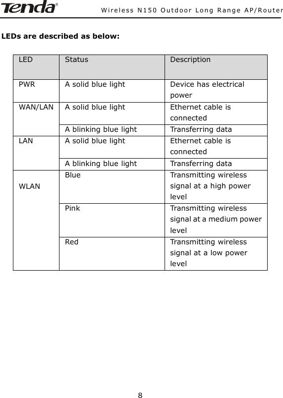
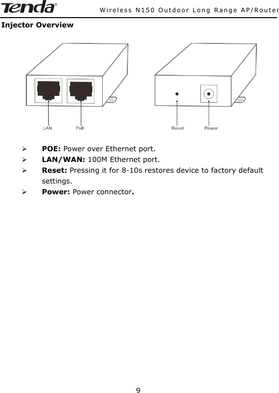
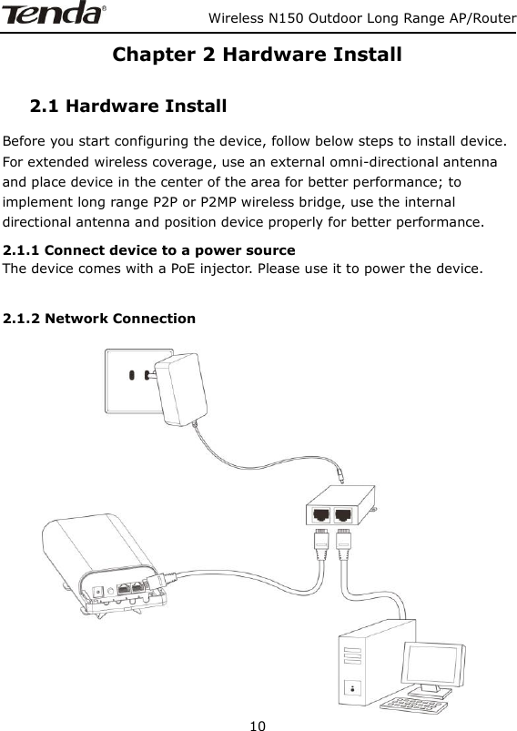
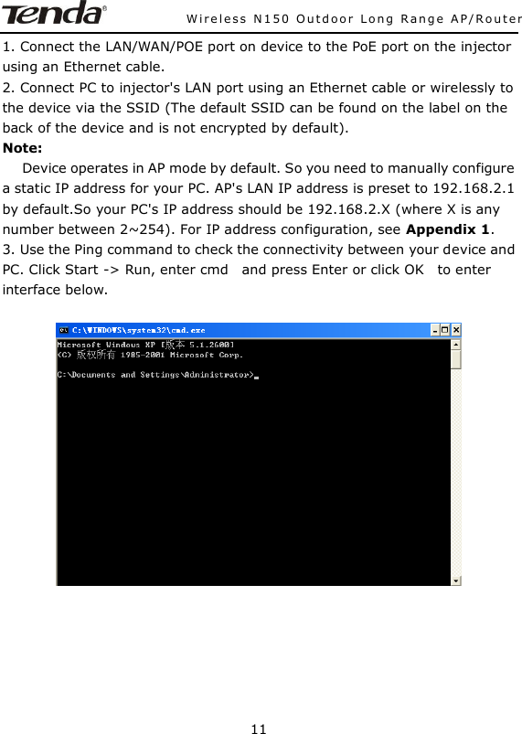
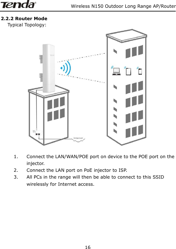
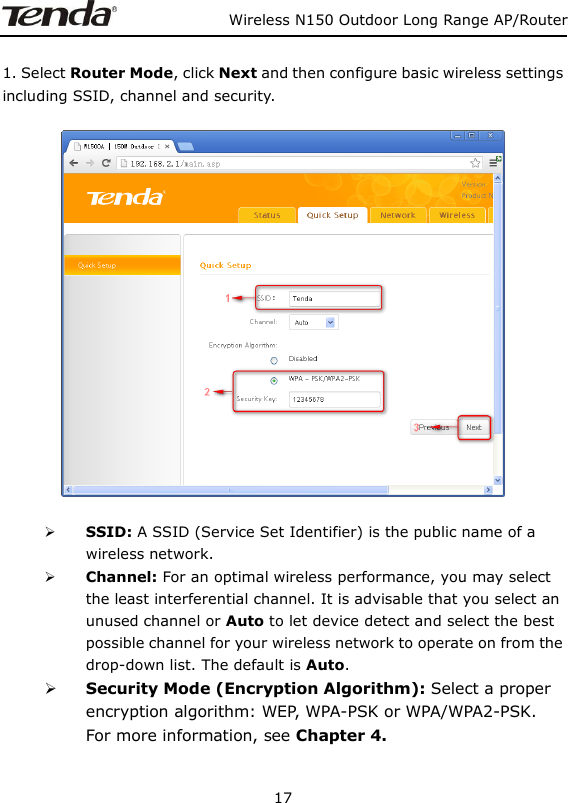
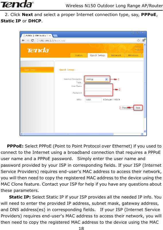
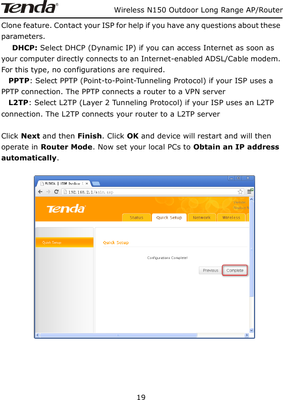
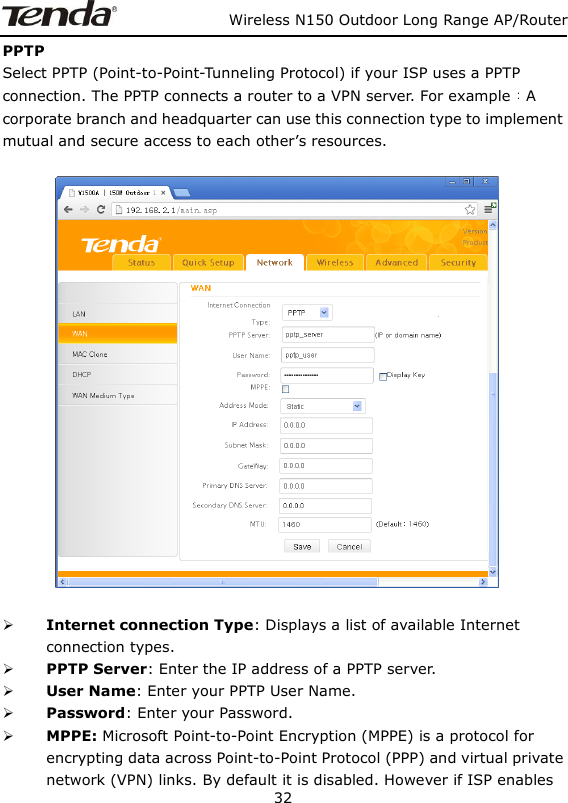
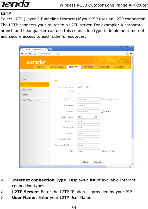
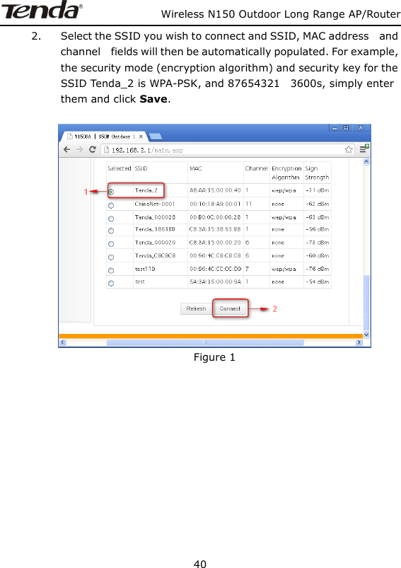
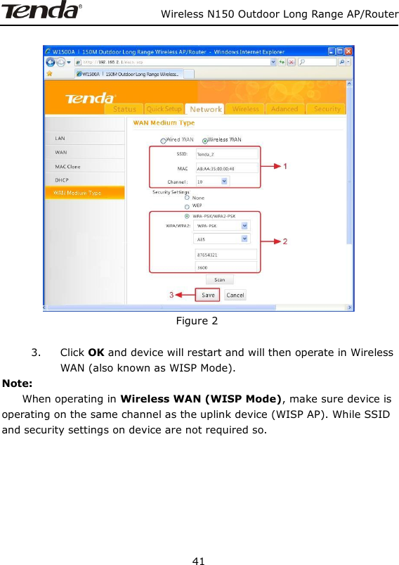
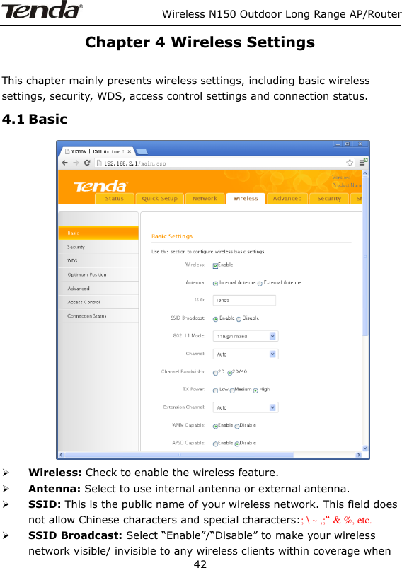
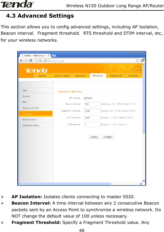
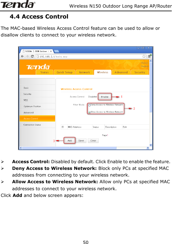
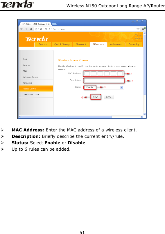
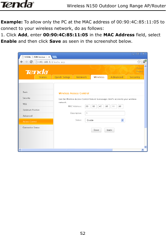
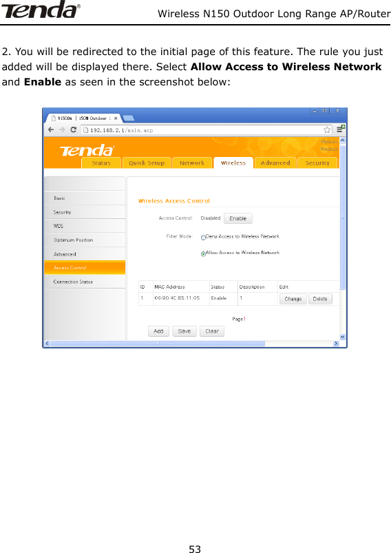
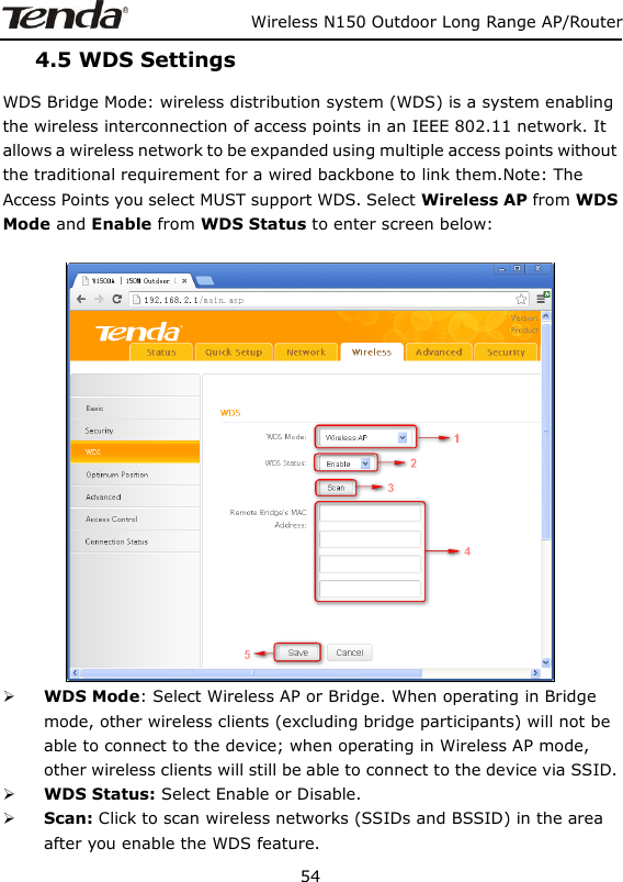
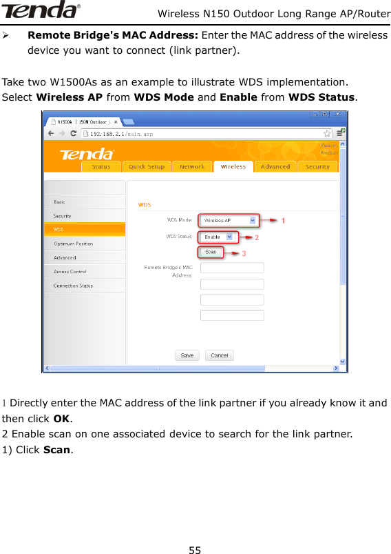
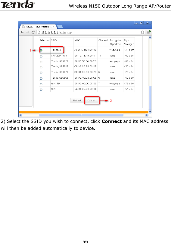
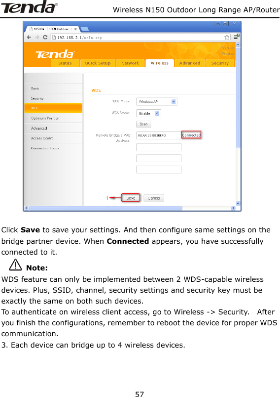
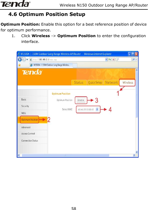
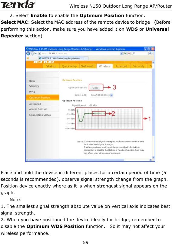
SHENZHEN TENDA TECHNOLOGY CO., LTD. Wireless N150 Outdoor Long Range AP/Router

User manual

                           Wireless N150 Long Range AP/Router 0
                  Wireless N150 Outdoor Long Range AP/Router 1   Copyright Statement is the registered trademark of Shenzhen Tenda Technology Co., Ltd. All the products and product names mentioned herein are the trademarks or registered trademarks of their respective holders. Copyright of the whole product as integration, including its accessories and software, belongs to Shenzhen Tenda Technology Co., Ltd. Without prior expressed written permission from Shenzhen Tenda Technology Co., Ltd, any individual or party is not allowed to copy, plagiarize, reproduce, or translate it into other languages. All photos and product specifications mentioned in this manual are for references only. Upgrades of software and hardware may occur; Tenda reserves the right to revise this publication and to make changes in the content hereof without obligation to notify any person or organization of such revisions or changes. If you would like to know more about our product information, please visit our website at http://www.tendacn.com.
             Wireless N150 Outdoor Long Range AP/Router  2  Table of Contents  Chapter 1 Product Overview ..........................................   5 1.1 Features   ............................................................................... 5 1.2 Package Content   .................................................................... 6 1.3 Panel Overview   ...................................................................... 7 Chapter 2 Hardware Install   .......................................... 10 2.1 Hardware Install   .................................................................. 10 2.1.1 Connect device to a power source   .................................. 10 2.1.2 Network Connection   ..................................................... 10 2.2 Quick Setup  ......................................................................... 13 2.2.1 AP Mode   ..................................................................... 15 2.2.2 Router Mode   ............................................................... 16 2.2.3 Universal Repeater Mode   .............................................. 20 Chapter 3 Network Setup   ............................................. 26 3.1 LAN Settings   ....................................................................... 26 3.2. WAN Settings ......................................................................   27 3.3 MAC Clone   .......................................................................... 36 3.4. DHCP   ................................................................................. 37 3.5 WAN Medium Type   ............................................................... 39 Chapter 4 Wireless Settings   ......................................... 42 4.1 Basic   .................................................................................. 42 4.2 Security   .............................................................................. 44 4.2.1 WPA-PSK   .................................................................... 44 4.2.2 WPA2-PSK   .................................................................. 46 4.2.3 WEP   ........................................................................... 47
             Wireless N150 Outdoor Long Range AP/Router  3  4.3 Advanced Settings  ................................................................ 48 4.4 Access Control   ..................................................................... 50 4.5 WDS Settings   ...................................................................... 54 4.6 Optimum Position Setup   ........................................................ 58 4.7 ConnectionStatus   ................................................................. 60 Chapter5 Advanced Applications   .................................. 61 5.1 Bandwidth Settings   .............................................................. 61 5.2 Connection status   ................................................................. 62 5.3 DDNS   ................................................................................. 63 5.4 Virtual Server   ...................................................................... 66 5.5 DMZ Host   ............................................................................ 68 5.6 UPnP   .................................................................................. 69 5.7 Routing Table   ....................................................................... 70 5.8 Static Routing   ...................................................................... 71 Chapter 6. Security Settings   ......................................... 72 6.1 Mac Address Filter   ................................................................ 72 6.2 Client Filter   ......................................................................... 75 6.3 URL Filter   ............................................................................ 78 6.4 Remote Web Management   ..................................................... 80 Chapter 7 SNMP   ............................................................ 82 Chapter 8 System tools   ................................................. 83 8.1 Syslog   ................................................................................ 83 8.2 Statistics   ............................................................................. 84 8.3 Time & Date   ........................................................................ 85 8.4 Change Password   ................................................................. 86 8.5 Backup ................................................................................   87 8.6 Restore   ............................................................................... 88 8.7 Firmware Update  .................................................................. 89 8.8 Restore to Factory Default   ..................................................... 90
                  Wireless N150 Outdoor Long Range AP/Router 4  8.9 Reboot 91 Appendix 1 TCP/IP Settings   ......................................... 92 Appendix 2: Glossary   .................................................... 99 Appendix 3 FAQs   ........................................................ 101 Appendix 4 Safety and Emission Statement   ................ 104
                  Wireless N150 Outdoor Long Range AP/Router 5  Chapter 1 Product Overview Thanks for purchasing thisW1500A Wireless N150 Outdoor Long Range AP/Router.    The Tenda W1500A is an outdoor long range wireless AP/router with wireless speed up to 150M. Combining the function of a wireless router, wireless AP, WISP, Client+AP and WDS, etc. the device nicely stands out in outdoor long range wireless connections, P2P, P2MP networking, wireless monitoring applications and much more.The W1500A is housed in an IP64 water/dust-proof enclosure. Also, it is lightning proof and power tunable. In addition to    internal antenna design, it comes with an optional external antenna connector    for DIY or upgrade. Plus, it is PoE capable and can be reset remotely.   1.1 Features  Compliant with IEEE802.11n and backward compatible with IEEE802.11g/b  Up to 150Mbps over 2.4G  5 operating modes: Wireless Router, Wireless AP, Wireless WAN (WISP), Universal Repeater (Client+AP) and Bridge  Internal 10dBi directional antenna;    plus optional external RP-SMA antenna connector    for DIY or upgrade (To use an external antenna, you must first shift antenna type from internal to external on wireless module)  Power tunable at 3 levels: high, medium and low  Able to be powered by a passive PoE injector; flexibly deploy your AP at ease  6000V lightning proof design (bidirectional);    Provides encryption methods of 64-/128-bit WEP, WPA-PSK and WPA2-PSK, etc to secure your wireless network  Provides 1 WAN/LAN/PoE interchangeable port and 1 separate LAN port
              Wireless N150 Outdoor Long Range AP/Router 6   Wireless Roaming technology to ensure high-efficiency wireless connectivity  Access Control based on MAC address  Provides logs    to record device's usage status;  Watchdog helps to recover system upon network failure  Able to reset AP using the Reset button on the PoE injector  Allow/disallow specified PCs on LAN to access Internet while operating in Router Mode  Support virtual server and DMZ host when operating in Router Mode  Support internal firewall to block attacks from hackers when operating in Router Mode 1.2 Package Content Unpack the box and verify the following items:  W1500A x 1  Screw x 2  Nylon Ligature x 2  Plastic Bag x 2  Ethernet Cable x 1  Power Adapter x 1  Injector x 1  Installation Guide x 1 If any of the above items are incorrect, missing, or damaged, please contact your Tenda reseller for immediate replacement.
             Wireless N150 Outdoor Long Range AP/Router 7  1.3 Panel Overview     LAN/WAN/POE: Provides 1 WAN/LAN/PoE interchangeable port, which functions as a WAN/PoE interchangeable port in router mode and a LAN/PoE port in AP mode.  LAN: Provides 1 10/100M LAN port.  SMA interface:RP-SMA connector for external antenna.  GND: Connect GND port on device to the ground using a copper wire for better lightning-proof
              Wireless N150 Outdoor Long Range AP/Router 8   LEDs are described as below:  LED Status Description PWR A solid blue light Device has electrical power WAN/LAN A solid blue light Ethernet cable is connected A blinking blue light Transferring data LAN A solid blue light Ethernet cable is connected A blinking blue light Transferring data  WLAN Blue Transmitting wireless signal at a high power level Pink Transmitting wireless signal at a medium power level Red Transmitting wireless signal at a low power level
              Wireless N150 Outdoor Long Range AP/Router 9  Injector Overview      POE: Power over Ethernet port.  LAN/WAN: 100M Ethernet port.  Reset: Pressing it for 8-10s restores device to factory default settings.  Power: Power connector.
                  Wireless N150 Outdoor Long Range AP/Router 10  Chapter 2 Hardware Install 2.1 Hardware Install Before you start configuring the device, follow below steps to install device. For extended wireless coverage, use an external omni-directional antenna and place device in the center of the area for better performance; to implement long range P2P or P2MP wireless bridge, use the internal directional antenna and position device properly for better performance. 2.1.1 Connect device to a power source The device comes with a PoE injector. Please use it to power the device.  2.1.2 Network Connection
              Wireless N150 Outdoor Long Range AP/Router 11  1. Connect the LAN/WAN/POE port on device to the PoE port on the injector using an Ethernet cable.   2. Connect PC to injector's LAN port using an Ethernet cable or wirelessly to the device via the SSID (The default SSID can be found on the label on the back of the device and is not encrypted by default). Note:    Device operates in AP mode by default. So you need to manually configure a static IP address for your PC. AP's LAN IP address is preset to 192.168.2.1 by default.So your PC's IP address should be 192.168.2.X (where X is any number between 2~254). For IP address configuration, see Appendix 1. 3. Use the Ping command to check the connectivity between your device and PC. Click Start -> Run, enter cmd    and press Enter or click OK    to enter interface below.
                 Wireless N150 Outdoor Long Range AP/Router 12  4. Input ping 192.168.2.1 and press Enter.      If you get a screen as shown in the screenshot above, your PC and device are interconnected.
                  Wireless N150 Outdoor Long Range AP/Router 13  If you get a screen as shown in the screenshot above, your PC and device are not interconnected. Please follow below steps to troubleshoot the problem. 1) Verify Ethernet cable connection The LAN LED on the device and PC's adapter LED should be on. 2) Verify TCP/IP settings on your    PC To access device web utility while operating in AP mode or universal repeater mode,    manually configure a static IP address for the PC. Just note that the IP address you configure must be on the same net segment as device LAN IP address. While in router mode, you can either manually specify an IP address for the PC or set it to Obtain an IP address automatically. 2.2 Quick Setup The device is configurable and manageable through a web browser. Launch a web browser, in the address bar, input 192.168.2.1 and press Enter. Enter admin in both User Name and Password fields (Both default user name and password are admin).
                  Wireless N150 Outdoor Long Range AP/Router 14  Click Login on    the login window, and then click Quick Setup. Select a proper mode for device to operate on from AP Mode, Router Mode and Universal Repeater Mode.     Operating Mode Overview:      AP Mode: In this mode, the device converts the wired signal into wireless signals, extending existing network coverage. It works as a central access point for multiple wireless clients (generally, wireless adapters) concurrently.  Router Mode: Operating in this mode, device functions as a regular wireless router. It supports PPPoE, dynamic IP (DHCP) , PPTP, L2TP and static IP Internet connection types and provide DHCP server feature that dynamically assigns IP addresses to DHCP-client-capable PCs for Internet connection sharing.   Wireless WAN (WISP) and WDS features are available in this mode.    Universal Repeater Mode(Client+AP): Device wirelessly bridges an uplink device to repeat wireless and extend coverage.
                  Wireless N150 Outdoor Long Range AP/Router 15  2.2.1 AP Mode       See below for the typical network topology. Position device properly according to practical network environment.    1. Connect the LAN/WAN/POE port on device to the POE port on the injector. 2. Connect the LAN port on the PoE injector to an uplink switch or router.   3. All PCs in the range will then be able to connect to this SSID wirelessly for Internet access.     Device operates in AP mode by default, so simply follow the topology above to establish th network. To configure other features like wireless, simply access the device web management utility.    For details, see Chapter
                  Wireless N150 Outdoor Long Range AP/Router 16  2.2.2 Router Mode    Typical Topology:   1. Connect the LAN/WAN/POE port on device to the POE port on the injector. 2. Connect the LAN port on PoE injector to ISP. 3. All PCs in the range will then be able to connect to this SSID wirelessly for Internet access.
                  Wireless N150 Outdoor Long Range AP/Router 17   1. Select Router Mode, click Next and then configure basic wireless settings including SSID, channel and security.               SSID: A SSID (Service Set Identifier) is the public name of a wireless network.  Channel: For an optimal wireless performance, you may select the least interferential channel. It is advisable that you select an unused channel or Auto to let device detect and select the best possible channel for your wireless network to operate on from the drop-down list. The default is Auto.  Security Mode (Encryption Algorithm): Select a proper encryption algorithm: WEP, WPA-PSK or WPA/WPA2-PSK.   For more information, see Chapter 4.
                  Wireless N150 Outdoor Long Range AP/Router 18    2. Click Next and select a proper Internet connection type, say, PPPoE, Static IP or DHCP.       PPPoE: Select PPPoE (Point to Point Protocol over Ethernet) if you used to connect to the Internet using a broadband connection that requires a PPPoE user name and a PPPoE password.    Simply enter the user name and password provided by your ISP in corresponding fields. If your ISP (Internet Service Providers) requires end-user's MAC address to access their network, you will then need to copy the registered MAC address to the device using the MAC Clone feature. Contact your ISP for help if you have any questions about these parameters.      Static IP: Select Static IP if your ISP provides all the needed IP info. You will need to enter the provided IP address, subnet mask, gateway address, and DNS address(es) in corresponding fields.    If your ISP (Internet Service Providers) requires end-user's MAC address to access their network, you will then need to copy the registered MAC address to the device using the MAC
                  Wireless N150 Outdoor Long Range AP/Router 19  Clone feature. Contact your ISP for help if you have any questions about these parameters.    DHCP: Select DHCP (Dynamic IP) if you can access Internet as soon as your computer directly connects to an Internet-enabled ADSL/Cable modem.   For this type, no configurations are required.   PPTP: Select PPTP (Point-to-Point-Tunneling Protocol) if your ISP uses a PPTP connection. The PPTP connects a router to a VPN server    L2TP: Select L2TP (Layer 2 Tunneling Protocol) if your ISP uses an L2TP connection. The L2TP connects your router to a L2TP server    Click Next and then Finish. Click OK and device will restart and will then operate in Router Mode. Now set your local PCs to Obtain an IP address automatically.
                  Wireless N150 Outdoor Long Range AP/Router 20  2.2.3 Universal Repeater Mode    Typical Topology:                     AP1 that operates in Router Mode has connected to Internet. AP2 connects to AP1 using the Universal Repeater Mode. So, clients that connect to AP2 can also access Internet.   1. Select Universal Repeater Mode on Quick Setup screen and then click   Next.
                  Wireless N150 Outdoor Long Range AP/Router 21  2. Click Scan and all wireless networks in the area will be displayed. Select the SSID (the name of a wireless network) you wish to connect, say, Tenda_2, and then click Next.
                  Wireless N150 Outdoor Long Range AP/Router 22   SSID, MAC address and channel fields will be populated automatically.
                  Wireless N150 Outdoor Long Range AP/Router 23   3. What you need to do is to configure the security settings. For example, the Security Mode, Security Key and Key Update Interval for the SSID Tenda_2is WPA-PSK, 87654321 and 3600s, simply enter them.
                  Wireless N150 Outdoor Long Range AP/Router 24   4. Click Next and configure wireless settings for the device. Device MUST operate on the same channel as the uplink AP for successful implementation of the feature. The channel field on device greyed out in this mode. SSID and security settings are configurable (both can be different from the uplink device).
                  Wireless N150 Outdoor Long Range AP/Router 25   5. Click Next and then Finish. Click OK and device will restart and will then operate in Universal Repeater Mode.   Now set your local PCs to Obtain an IP address automatically and these PCs will then use IP/gateway/DNS addresses assigned by the uplink device to access Internet.
                  Wireless N150 Outdoor Long Range AP/Router 26  Chapter 3 Network Setup    This chapter mainly explains LAN settings in AP Mode, Universal Repeater Mode and Router Mode, as well as WAN settings, MAC Clone, DHCP server and WAN Medium Type (Wired or Wireless WAN). 3.1 LAN Settings           IP Address: Device's LAN IP address, 192.168.2.1 by default. You can change it according to your needs; just remember to use the new one to log on to the device’s web utility if you changed it.  Subnet Mask: Device’s LAN subnet mask, 255.255.255.0 by default.  Note: If you change the device’s LAN IP address, you must use the new one to log on to the web-based configuration utility. To synchronize system time in AP Mode and Universal Repeater Mode, make sure your device's LAN IP address is on the same net segment as the uplink device, and set gateway and DNS addresses the same as uplink device's IP address.
                  Wireless N150 Outdoor Long Range AP/Router 27  3.2. WAN Settings WAN settings are only available in Router Mode. PPPoE     Internet connection Type: Displays the current Internet connection type.   User Name: Enter the User Name provided by your ISP.   Password: Enter the password provided by your ISP.  MPPE: Microsoft Point-to-Point Encryption (MPPE) is a protocol for encrypting data across Point-to-Point Protocol (PPP) and virtual private network (VPN) links.By default it is disabled. However if ISP enables MPPE on his PPPoE server, you must also enable it on
                  Wireless N150 Outdoor Long Range AP/Router 28  the device. Consult your ISP, if you don't know whether he has enabled the MPPE or not.  MTU: Maximum Transmission Unit. DO NOT change it from the factory default of 1492 unless necessary. You may need to change it for optimal performance with some specific websites or application software that cannot be opened or enabled; in this case, try 1450, 1400, etc.
                  Wireless N150 Outdoor Long Range AP/Router 29  Static IP    If your ISP assigns a fixed IP address to you, then select Static IP, and enter the IP address, subnet mask, primary DNS and secondary DNS (optional) info provided by your ISP in corresponding fields.  IP Address: Enter the WAN IP address provided by your ISP. Consult your ISP if you are not clear.  Subnet Mask: Enter WAN Subnet Mask provided by your ISP. The default is 255.255.255.0.  Gateway: Enter the WAN Gateway provided by your ISP. Consult your ISP if you are not clear.
                  Wireless N150 Outdoor Long Range AP/Router 30   Primary DNS Server: Enter the DNS address provided by your ISP.  Secondary DNS Server: Enter the other DNS address if your ISP provides 2 such addresses (optional).  MTU: Maximum Transmission Unit. DO NOT change it from the factory default of 1500 unless necessary. You may need to change it for optimal performance with some specific websites or application software that cannot be opened or enabled; in this case, try 1450, 1400, etc.
                  Wireless N150 Outdoor Long Range AP/Router 31  DHCP (Dynamic IP) Select DHCP (Dynamic IP) if you can access Internet as soon as your computer directly connects to an Internet-enabled ADSL/Cable modem. Device will automatically obtain an IP address from ISP.
                  Wireless N150 Outdoor Long Range AP/Router 32  PPTP Select PPTP (Point-to-Point-Tunneling Protocol) if your ISP uses a PPTP connection. The PPTP connects a router to a VPN server. For example:A corporate branch and headquarter can use this connection type to implement mutual and secure access to each other’s resources.                      Internet connection Type: Displays a list of available Internet connection types.  PPTP Server: Enter the IP address of a PPTP server.  User Name: Enter your PPTP User Name.  Password: Enter your Password.  MPPE: Microsoft Point-to-Point Encryption (MPPE) is a protocol for encrypting data across Point-to-Point Protocol (PPP) and virtual private network (VPN) links. By default it is disabled. However if ISP enables
                  Wireless N150 Outdoor Long Range AP/Router 33  MPPE on his PPPoE server, you must also enable it on the device. Consult your ISP, if you don't know whether he has enabled the MPPE or not.  Address mode: Select “Dynamic” if you don’t get any IP info from your ISP, otherwise select “Static”. Consult your ISP if you are not clear.  IP Address: Enter the IP address provided by your ISP. Consult your local ISP if you are not clear.  Subnet Mask: Enter the subnet mask provided by your ISP. Consult your ISP if you are not clear.  Gateway: Enter the gateway provided by your ISP. Consult your local ISP if you are not clear.  Primary/Secondary DNS Server: Enter the Primary and Secondary DNS Server Addresses. Consult your local ISP if you are not clear.  MTU: Maximum Transmission Unit. The factory default is 1460.
                  Wireless N150 Outdoor Long Range AP/Router 34  L2TP Select L2TP (Layer 2 Tunneling Protocol) if your ISP uses an L2TP connection. The L2TP connects your router to a L2TP server. For example: A corporate branch and headquarter can use this connection type to implement mutual and secure access to each other’s resources.     Internet connection Type: Displays a list of available Internet connection types.  L2TP Server: Enter the L2TP IP address provided by your ISP.  User Name: Enter your L2TP User Name.
                  Wireless N150 Outdoor Long Range AP/Router 35   Password: Enter your Password.  Address Mode: Select Dynamic if you don’t get any IP info from your ISP, otherwise select “Static”. Consult your ISP if you are not clear.  IP Address: Enter the IP address provided by your ISP. Consult your local ISP if you are not clear.  Gateway: Enter the gateway provided by your ISP. Consult your local ISP if you are not clear.  Primary/Secondary DNS Server: Enter the Primary and Secondary DNS Server Addresses. Consult your local ISP if you are not clear.  MTU: Maximum Transmission Unit. The factory default is 1458.
                  Wireless N150 Outdoor Long Range AP/Router 36  3.3 MAC Clone This section allows you to configure Device’s WAN MAC address. This feature is only available in Router Mode.      Normally you don't need to change device's default WAN MAC address. However, some ISPs may bind client PC's MAC address for Internet connection authentication. In this case, simply enter the bound MAC in the WAN MAC Address field or click "Copy My PC's MAC" (or Clone MAC) to copy your PC's MAC to the device.  MAC Address: Config device’s WAN MAC address and click Save to save your settings.  Clone MAC: Click to automatically copy your local PC's MAC address to the device as device's new WAN MAC address.  Restore to Factory Default MAC: Reset Device’s WAN MAC to factory default.
                  Wireless N150 Outdoor Long Range AP/Router 37  3.4. DHCP   The Dynamic Host Configuration Protocol (DHCP) is an automatic configuration protocol used on IP networks. If you enable the built-in DHCP server on this device, it will automatically configure TCP/IP protocol settings for all DHCP-Client-enabled PCs in your LAN (Namely, PCs are set to "Obtain an IP address automatically" and "Obtain DNS server address automatically"), including IP address, subnet mask, gateway and DNS etc, eliminating the need for manual intervention.    DHCP Server: enable or disable the device’s DHCP server feature. If enabled, the DHCP server will assign IP addresses to requesting clients.  Start IP Address: Specify the starting IP address for the DHCP server IP assignment.
                  Wireless N150 Outdoor Long Range AP/Router 38   End IP Address: Specify the ending IP address for the DHCP server IP assignment.  Primary DNS Server: Specify a primary DNS address for requesting clients.  Secondary DNS Server: Specify a secondary DNS address for requesting clients. This field is optional.  Lease Time: The length of time for the IP address lease. Configuring a proper lease time improves the efficiency for the DHCP server to reclaim disused IP addresses.  For example: If the lease time is set to one hour, then the DHCP server will reclaim disused IP addresses every hour.
                  Wireless N150 Outdoor Long Range AP/Router 39  3.5 WAN Medium Type      Here you can select a proper WAN medium type to use: Wireless WAN (WISP) or Wired WAN to connect to the uplink device. Internet connection types are the same for the two medium types.  Wired WAN: Connect to uplink device via an Ethernet cable.  Wireless WAN: Connect to uplink device (WISP AP) wirelessly. Please do following the steps as below if you connect to the Internet wirelessly.  1. Select Wireless WAN (WISP) and click Scan. Currently available wireless networks will then be displayed.
                  Wireless N150 Outdoor Long Range AP/Router 40  2. Select the SSID you wish to connect and SSID, MAC address    and channel    fields will then be automatically populated. For example, the security mode (encryption algorithm) and security key for the SSID Tenda_2 is WPA-PSK, and 87654321    3600s, simply enter them and click Save.     Figure 1
                  Wireless N150 Outdoor Long Range AP/Router 41                                  Figure 2  3. Click OK and device will restart and will then operate in Wireless WAN (also known as WISP Mode). Note:     When operating in Wireless WAN (WISP Mode), make sure device is operating on the same channel as the uplink device (WISP AP). While SSID and security settings on device are not required so.
                  Wireless N150 Outdoor Long Range AP/Router 42  Chapter 4 Wireless Settings This chapter mainly presents wireless settings, including basic wireless settings, security, WDS, access control settings and connection status. 4.1 Basic   Wireless: Check to enable the wireless feature.    Antenna: Select to use internal antenna or external antenna.  SSID: This is the public name of your wireless network. This field does not allow Chinese characters and special characters:; \ ~ ,;“ & %, etc.  SSID Broadcast: Select “Enable”/“Disable” to make your wireless network visible/ invisible to any wireless clients within coverage when
                  Wireless N150 Outdoor Long Range AP/Router 43  they perform a scan to see what’s available. When disabled, this SSID becomes invisible to any wireless clients within the coverage. Manually enter the SSID if you want to connect to it.  802.11 Mode:  Select a wireless network mode. 11b mode: Select it if you have only Wireless-B clients in your wireless network. 11g mode: Select it if you have only Wireless-G clients in your wireless network.  11b/g mixed mode: Select it if you have only Wireless-B and Wireless-G clients in your wireless network.  11b/g/n mixed mode: Select it if you have Wireless-b/g/n clients in your wireless network.  Channel: For an optimal wireless performance, you may select the least interferential channel. It is advisable that you select an unused channel or Auto to let device detect and select the best possible channel for your wireless network to operate on from the drop-down list.  Channel Bandwidth: Select a proper channel bandwidth to enhance wireless performance. When there are 11b/g and 11n wireless clients, please select the 802.11n mode of 40M frequency band; when there are only non-11n wireless clients, select 20M frequency band mode; when the wireless network mode is 11n mode, please select 20/40 frequency band to boost its throughput.  TX Power: Select a proper transmission power level for device (Low power: 100mW, medium power: 200mW, high power: 300mW). The default TX power level is High.  Extension Channel: It is used to ensure N speed for 802.11n devices on the network.  WMM-Capable: WMM is QoS for your wireless network. Enabling this option may better stream wireless multimedia data (such as video or audio).  ASPD Capable: Select to enable/disable the auto power saving mode.
                  Wireless N150 Outdoor Long Range AP/Router 44  4.2 Security This section allows you to secure your wireless network to block unauthorized accesses and malicious packet sniffing. For better security, it is advisable to use the WPA-AES encryption. 4.2.1 WPA-PSK   The WPA protocol implements the majority of the IEEE 802.11i standard. It enhances data encryption through the Temporal Key Integrity Protocol (TKIP) which is a 128-bit per-packet key, meaning that it dynamically generates a new key for each packet. WPA also includes a message integrity check feature to prevent data packets from being hampered with. Only authorized network users can access the wireless network. WPA adopts enhanced encryption algorithm over WEP.
                  Wireless N150 Outdoor Long Range AP/Router 45    Cipher Type: Select AES (advanced encryption standard),    or TKIP (temporary key integrity protocol).  Security Key: Enter a security key, which must be between 8-63 ASCII characters long or 64 HEX characters long.  Key Renewal Interval: Specify a valid time interval for the key to be updated.
                  Wireless N150 Outdoor Long Range AP/Router 46  4.2.2 WPA2-PSK   The later WPA2 protocol features compliance with the full IEEE 802.11i standard and uses Advanced Encryption Standard (AES) in addition to TKIP encryption protocol to guarantee better security than that provided by WEP or WPA.   Cipher Type: Select AES (advanced encryption standard) or TKIP (temporary key integrity protocol) &AES.  Security Key: Enter a security key, which must be between 8-63 ASCII characters long or 64 HEX characters long.  Key Renewal (Update)    Interval: Specify a valid time interval for the key to be updated.
                  Wireless N150 Outdoor Long Range AP/Router 47  4.2.3 WEP WEP is intended to provide data confidentiality comparable to that of a traditional wired network.     Authentication Type: Select a proper authentication type.  WEP Key Format: Select a proper key format: HEX or ASCII.  Key Select: Select a key from the preset keys 1-4 for current use.
                  Wireless N150 Outdoor Long Range AP/Router 48  4.3 Advanced Settings This section allows you to config advanced settings, including AP Isolation, Beacon interval,Fragment threshold,RTS threshold and DTIM interval, etc, for your wireless networks.     AP Isolation: Isolates clients connecting to master SSID.  Beacon Interval: A time interval between any 2 consecutive Beacon packets sent by an Access Point to synchronize a wireless network. Do NOT change the default value of 100 unless necessary.  Fragment Threshold: Specify a Fragment Threshold value. Any
                  Wireless N150 Outdoor Long Range AP/Router 49  wireless packet exceeding the preset value will be divided into several fragments before transmission. DO NOT change the default value of 2346 unless necessary.  RTS Threshold: If a packet exceeds such set value, RTS/CTS scheme will be used to reduce collisions. Set it to a smaller value provided that there are distant clients and interference. For normal SOHO, it is recommended to keep the default value unchanged; otherwise, device performance may be degraded.  DTIM Interval: A DTIM (Delivery Traffic Indication Message) Interval is a countdown informing clients of the next window for listening to broadcast and multicast messages. When such packets arrive at device’s buffer, the device will send DTIM (delivery traffic indication message) and DTIM interval to wake clients up for receiving these packets.
                  Wireless N150 Outdoor Long Range AP/Router 50  4.4 Access Control The MAC-based Wireless Access Control feature can be used to allow or disallow clients to connect to your wireless network.     Access Control: Disabled by default. Click Enable to enable the feature.  Deny Access to Wireless Network: Block only PCs at specified MAC addresses from connecting to your wireless network.  Allow Access to Wireless Network: Allow only PCs at specified MAC addresses to connect to your wireless network. Click Add and below screen appears:
                  Wireless N150 Outdoor Long Range AP/Router 51      MAC Address: Enter the MAC address of a wireless client.  Description: Briefly describe the current entry/rule.  Status: Select Enable or Disable.  Up to 6 rules can be added.
                  Wireless N150 Outdoor Long Range AP/Router 52   Example: To allow only the PC at the MAC address of 00:90:4C:85:11:05 to connect to your wireless network, do as follows: 1. Click Add, enter 00:90:4C:85:11:05 in the MAC Address field, select Enable and then click Save as seen in the screenshot below.
                  Wireless N150 Outdoor Long Range AP/Router 53   2. You will be redirected to the initial page of this feature. The rule you just added will be displayed there. Select Allow Access to Wireless Network and Enable as seen in the screenshot below:
                  Wireless N150 Outdoor Long Range AP/Router 54  4.5 WDS Settings WDS Bridge Mode: wireless distribution system (WDS) is a system enabling the wireless interconnection of access points in an IEEE 802.11 network. It allows a wireless network to be expanded using multiple access points without the traditional requirement for a wired backbone to link them.Note: The Access Points you select MUST support WDS. Select Wireless AP from WDS Mode and Enable from WDS Status to enter screen below:    WDS Mode: Select Wireless AP or Bridge. When operating in Bridge mode, other wireless clients (excluding bridge participants) will not be able to connect to the device; when operating in Wireless AP mode, other wireless clients will still be able to connect to the device via SSID.  WDS Status: Select Enable or Disable.  Scan: Click to scan wireless networks (SSIDs and BSSID) in the area after you enable the WDS feature.
                  Wireless N150 Outdoor Long Range AP/Router 55   Remote Bridge's MAC Address: Enter the MAC address of the wireless device you want to connect (link partner).  Take two W1500As as an example to illustrate WDS implementation.   Select Wireless AP from WDS Mode and Enable from WDS Status.   1 Directly enter the MAC address of the link partner if you already know it and then click OK. 2 Enable scan on one associated device to search for the link partner. 1) Click Scan.
                  Wireless N150 Outdoor Long Range AP/Router 56    2) Select the SSID you wish to connect, click Connect and its MAC address will then be added automatically to device.
                  Wireless N150 Outdoor Long Range AP/Router 57    Click Save to save your settings. And then configure same settings on the bridge partner device. When Connected appears, you have successfully connected to it.     Note: WDS feature can only be implemented between 2 WDS-capable wireless devices. Plus, SSID, channel, security settings and security key must be exactly the same on both such devices. To authenticate on wireless client access, go to Wireless -> Security.    After you finish the configurations, remember to reboot the device for proper WDS communication.   3. Each device can bridge up to 4 wireless devices.
                  Wireless N150 Outdoor Long Range AP/Router 58  4.6 Optimum Position Setup Optimum Position: Enable this option for a best reference position of device for optimum performance. 1. Click Wireless -> Optimum Position to enter the configuration interface.
                  Wireless N150 Outdoor Long Range AP/Router 59  2. Select Enable to enable the Optimum Position function. Select MAC: Select the MAC address of the remote device to bridge . (Before performing this action, make sure you have added it on WDS or Universal Repeater section)    Place and hold the device in different places for a certain period of time (5 seconds is recommended), observe signal strength change from the graph. Position device exactly where as it is when strongest signal appears on the graph. Note: 1. The smallest signal strength absolute value on vertical axis indicates best signal strength. 2. When you have positioned the device ideally for bridge, remember to disable the Optimum WDS Position function.    So it may not affect your wireless performance.

Navigation menu