TENDA TECHNOLOGY W312A Wireless N300 Wall Plate Access Point User Manual
SHENZHEN TENDA TECHNOLOGY CO., LTD. Wireless N300 Wall Plate Access Point
User Manual
i

ii
Copyright Statement
is the registered trademark of Shenzhen Tenda Technology Co., Ltd. All
the products and product names mentioned herein are the trademarks or registered
trademarks of their respective holders. Copyright of the whole product as integration,
including its accessories and software, belongs to Shenzhen Tenda Technology Co., Ltd.
No part of this publication can be reproduced, transmitted, transcribed, stored in a
retrieval system, or translated into any language in any form or by any means without the
prior written permission of Shenzhen Tenda Technology Co., Ltd. If you would like to know
more about our product information, please visit our website at http://www.tendacn.com.
Disclaimer
Pictures, images and product specifications herein are for references only. To improve
internal design, operational function, and/or reliability, Tenda reserves the right to make
changes to the products described in this document without obligation to notify any person
or organization of such revisions or changes. Tenda does not assume any liability that
may occur due to the use or application of the product or circuit layout(s) described herein.
Every effort has been made in the preparation of this document to ensure accuracy of the
contents, but all statements, information and recommendations in this document do not
constitute the warranty of any kind, express or implied.
Technical Support
Website: http://www.tendacn.com
TEL: (86 755) 2765 7180
Email: support@tenda.com.cn
iii
About This User Guide
Thank you for choosing Tenda! Please read this user guide before you start! This user
guide instructs you to install and configure the device.
This user guide uses the following formats to highlight special messages:
Icon
Description
Note
This format is used to highlight information of importance or
special interest. Ignoring this type of note may result in
ineffective configurations, loss of data or damage to device.
Tip
This format is used to highlight a procedure that will save
time or resources.
How to Use This Guide
Chapter
Content
Ⅰ Product Overview
Describes product appearance and lists features.
Ⅱ Install
Explains how to install hardware and connect cables.
Ⅲ Login
Explains how to logs in to the web interface.
Ⅳ Features & Configurations
Introduces how to configure the device features.
Ⅴ Appendix
Explains how to configure PC TCP/IP settings, lists default
feature values and Safety and Emission Statement.

iv
Contents
I PRODUCT OVERVIEW ........................................................................................................................................ 1
1 What It Does ....................................................................................................................................... 1
2 Package Content ................................................................................................................................. 1
3 LED ..................................................................................................................................................... 2
4 Button & Interface .............................................................................................................................. 2
5 Label ................................................................................................................................................... 3
Ⅱ INSTALL .............................................................................................................................................................. 4
Ⅲ LOGIN .................................................................................................................................................................. 6
1 Configure PC TCP/IP Settings ............................................................................................................... 6
2 Log in to Device ................................................................................................................................... 6
Ⅳ FEATURES & CONFIGURATIONS .................................................................................................................. 8
1 Status ................................................................................................................................................. 8
1.1 System Status ........................................................................................................................................ 8
1.2 Wireless Status ...................................................................................................................................... 9
1.3 Traffic Statistics ...................................................................................................................................... 9
1.4 Wireless Clients ................................................................................................................................... 10
2 LAN Settings ..................................................................................................................................... 10
3 DHCP Server...................................................................................................................................... 11
3.1 DHCP Server ........................................................................................................................................ 11
3.2 DHCP Client List ................................................................................................................................... 13
4 Wireless Settings ............................................................................................................................... 13
4.1 Basic Settings ....................................................................................................................................... 14
4.2 Radio ................................................................................................................................................... 19
4.3 Advanced Settings ............................................................................................................................... 21
4.4 Access Control ..................................................................................................................................... 22
4.5 QVLAN ................................................................................................................................................. 23
5 SNMP ............................................................................................................................................... 24

v
6 Tools ................................................................................................................................................. 25
6.1 Firmware Upgrade & Reboot .............................................................................................................. 26
6.2 System Time & Login Timeout Setup .................................................................................................. 27
6.3 Syslog ................................................................................................................................................... 29
6.4 Log Settings ......................................................................................................................................... 30
6.5 Backup & Restore ................................................................................................................................ 30
6.6 Restore to Factory Default................................................................................................................... 31
6.7 User Name & Password ....................................................................................................................... 32
6.8 Diagnostics .......................................................................................................................................... 33
Ⅴ APPENDIX ....................................................................................................................................................... 34
1 Configure PC TCP/IP Settings ............................................................................................................. 34
Windows 7 ................................................................................................................................................ 34
Windows XP .............................................................................................................................................. 36
2 Factory Default Settings .................................................................................................................... 38
3 Safety and Emission Statement ......................................................................................................... 40

1
Ⅰ Product Overview
1 What It Does
This Wireless N300 Wall Plate Access Point, is a best-in-class 802.11n indoor access
point designed specifically for business-class environments such as hotels, airports,
coffee shops, shopping centers, sporting venues, and university campus. With standard
install design and stylish appearance, it nicely fits into an 86-type wall jack and seamlessly
blends in with most interior decorations in an office or room. No need to rebuild or change
existing walls. The unit comes with a built-in USB port that charges mobile devices such
as a smart phone via a USB cable as well as a RJ11 port for connecting to your telephone.
Integrated 802.3af Power over Ethernet (PoE) allows installation in areas where power
outlets are not readily available. Plus, it supports port “Bypass”. Client connected to the
device’s LAN port can still communicate with the remote uplink device (PoE switch) even
when no power is supplied to this device or it goes dead).
2 Package Content
Unpack the package. Your box should contain the following items:
AP
2*Screws
Ethernet Cable
Install Guide
Resource CD
If any of the parts are incorrect, missing, or damaged, contact your dealer. Keep the
carton, including the original packing materials, in case you need to return the product for
repair.
2
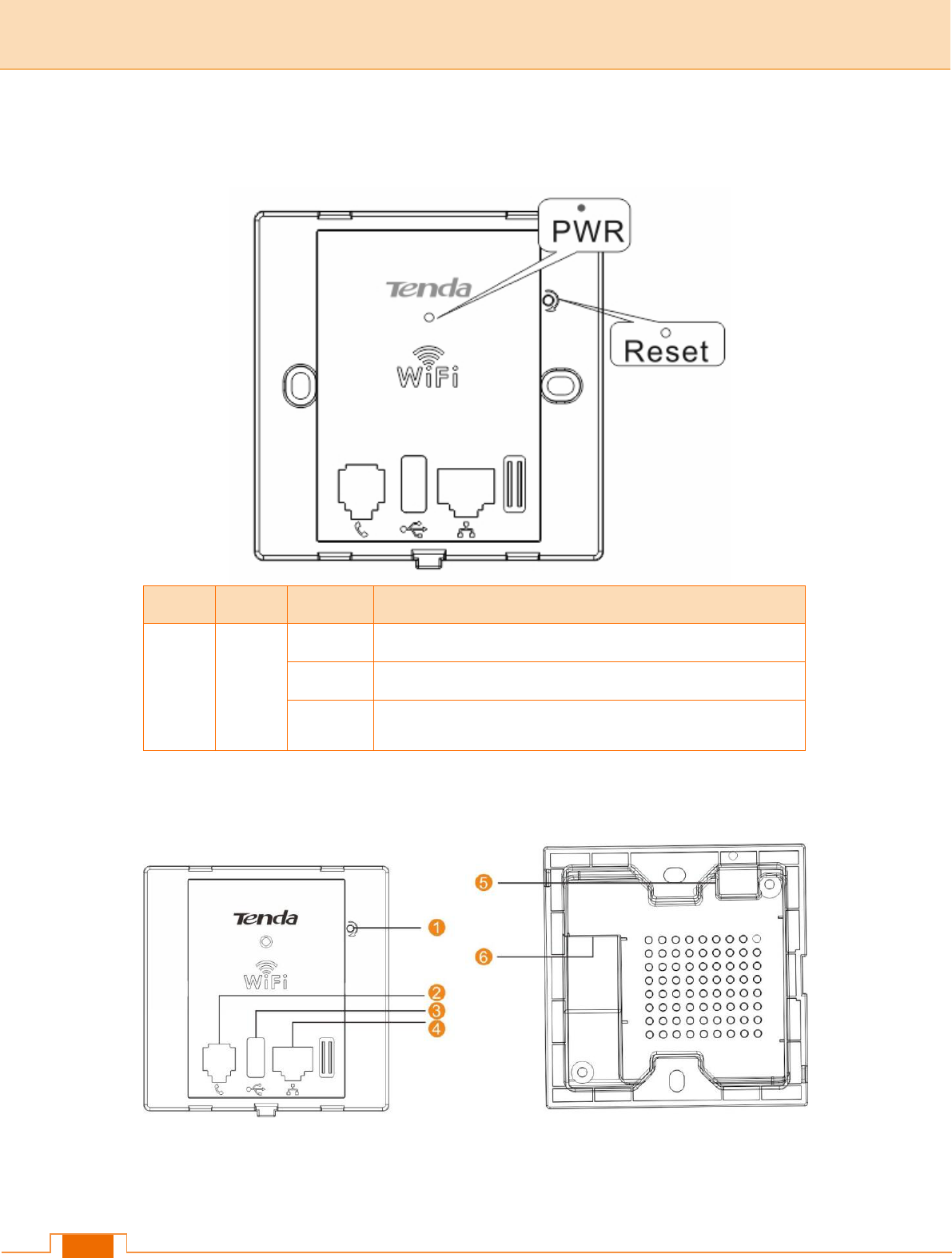
3 LED
LED
Color
Status
Description
PWR
Green
Solid
The device is connected to power supply.
Blinking
The device is functioning correctly.
Off
Power is not supplied to the device or the device is
malfunctioning.
4 Button & Interface
❶Reset: Open the housing of the AP and press this reset button with a needle for 7
seconds to restore the device to the factory default settings.
❷Phone Interface: For connection to a telephone.
3
❸USB Port: The USB port that charges terminal devices with a USB cable.
❹LAN: 100M Ethernet Port for connecting to an Ethernet LAN device such as a PC or
switch, etc. This port supports “Bypass”. Client connected to the device’s LAN port can still
communicate with the remote uplink device (PoE switch) even when no power is supplied
to this device or it goes dead).
❺Green Connector: For connecting to a 4-core phone cable.
❻RJ45: The RJ45 port for connecting to a PoE switch.
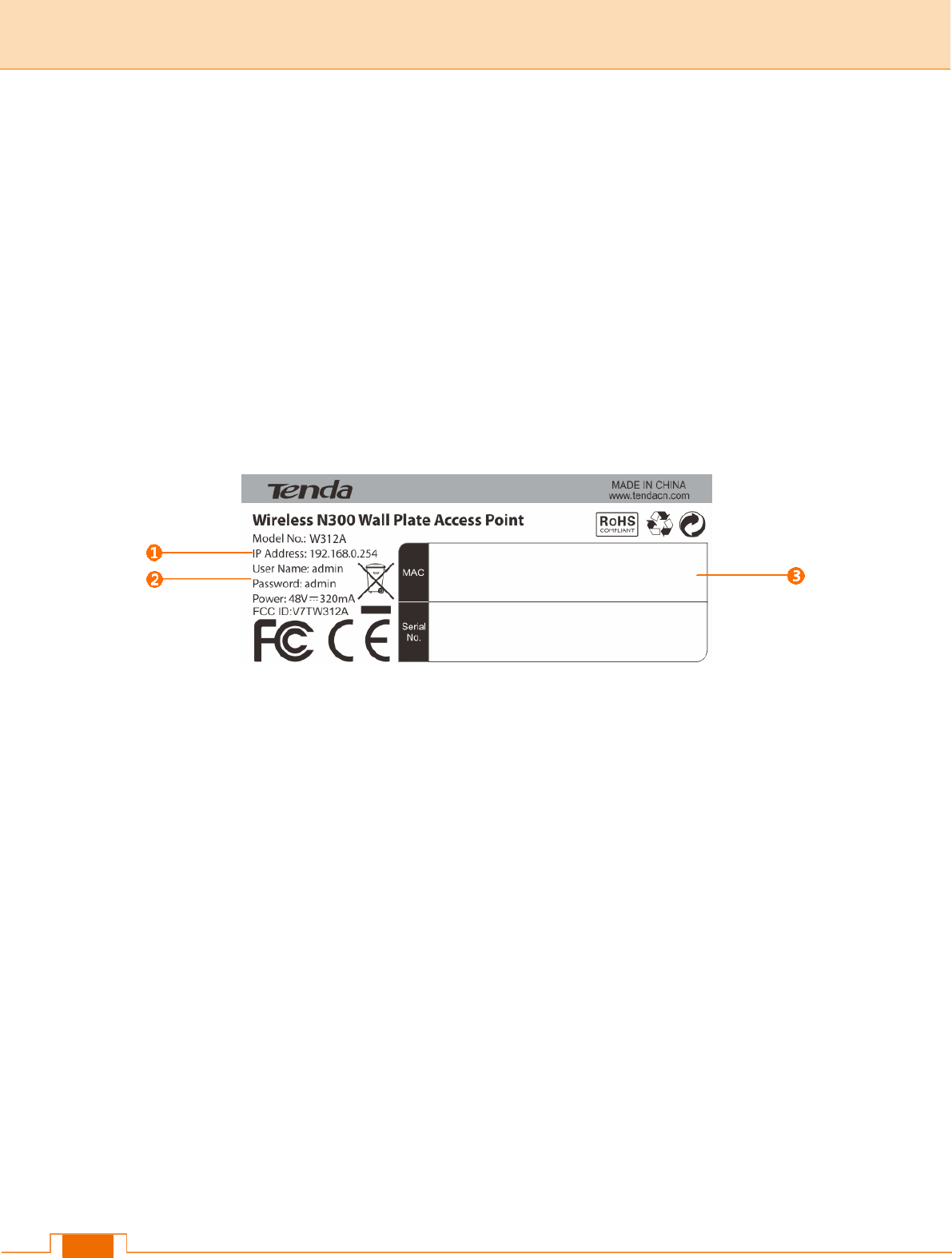
5 Label
❶Default Login IP address. This IP address is to be used to access the device’s
settings through a web browser. If you change it, you have to open a new connection to
the new IP address and log in again.
❷Administrator user name and password
❸This is the device’s MAC address. The device’s default primary SSID (wireless
network name) is Tenda_XXXXXX (where XXXXXX is the last 6 characters of this MAC
address).
4
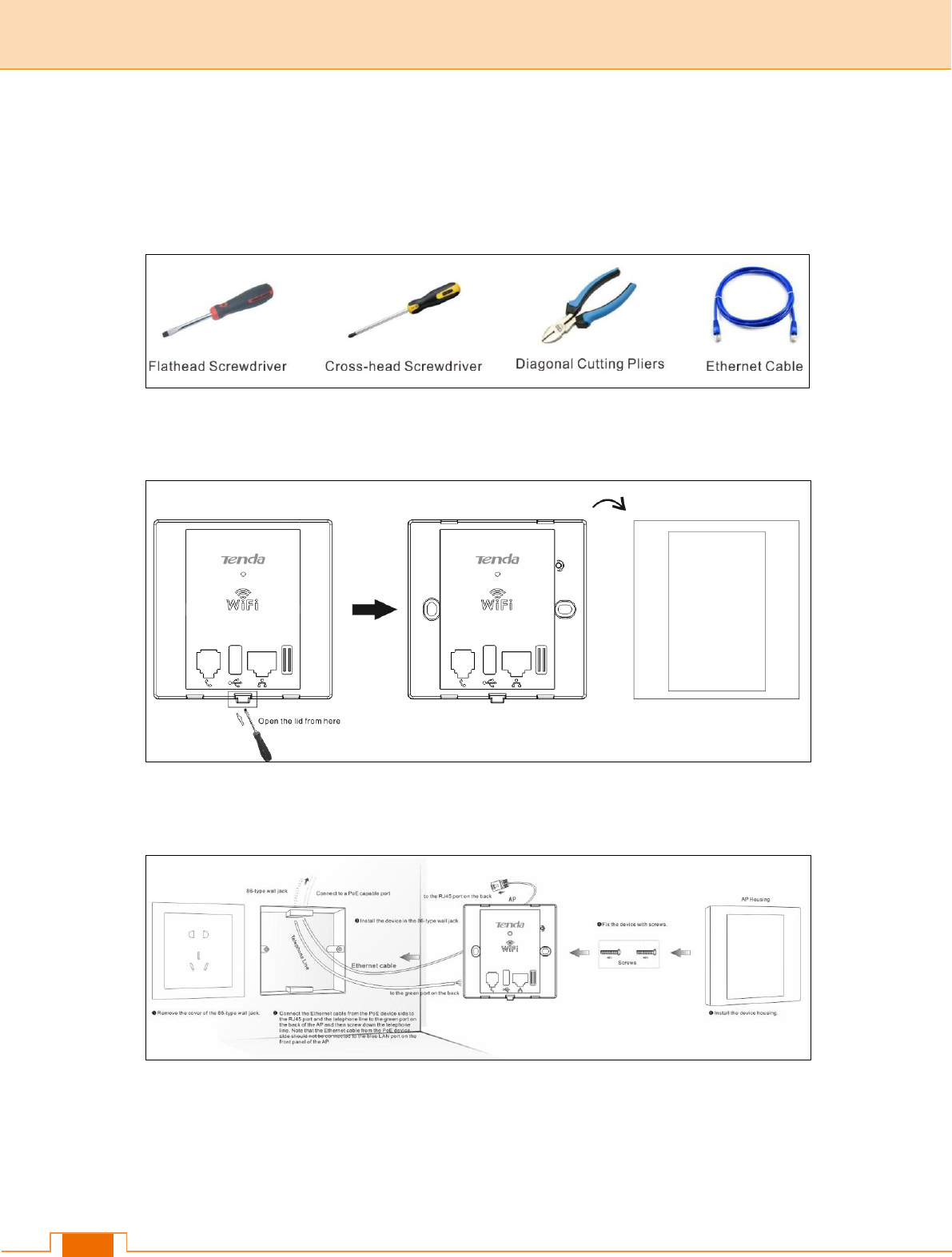
Ⅱ Install
Step 1: Prepare the following installation tools.
Step 2: Remove the device's lid with a flathead screwdriver.
Step 3: Install the device (For details, please go to the Install Guide).
5
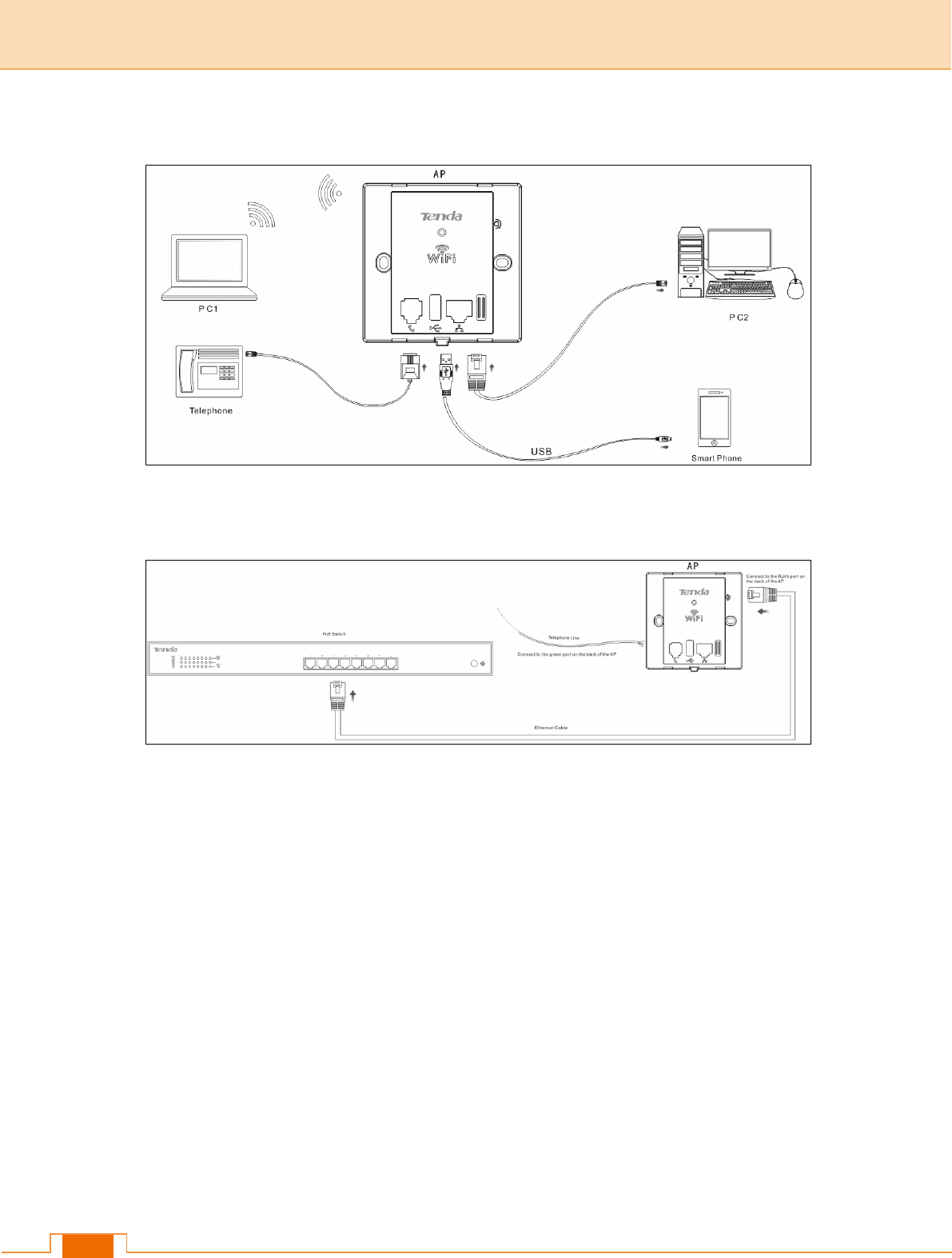
Step 4: Connect terminal device(s).
Step 5: Verify the network topology.

6
Ⅲ Login
1 Configure PC TCP/IP Settings
Connect your PC to this device wirelessly or using an Ethernet cable. The default IP
address of your wireless access point is 192.168.0.254. If you are using the default IP
subnet, the computer you are using to connect to the device should be configured with an
IP address that starts with 192.168.0.x (where x can be any integer between 2~253) and a
Subnet Mask of 255.255.255.0; if you have changed the subnet of the wireless access
point, the computer you are using to connect must be within the same subnet.
Tip
If you are not clear about how to set up your PC's IP address, see 1 Configure PC TCP/IP
Settings.
2 Log in to Device
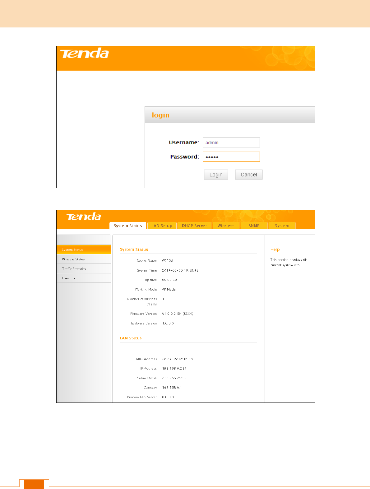
1) Launch a web browser, say, IE, input 192.168.0.254 and press Enter.
2) The login window appears. Enter the login user name and password (Both are
"admin" by default) and click Login.
Tip
You can click Tools -> User Name & Password to manage this user name and password.
For more information, see 6.7 User Name & Password.
7
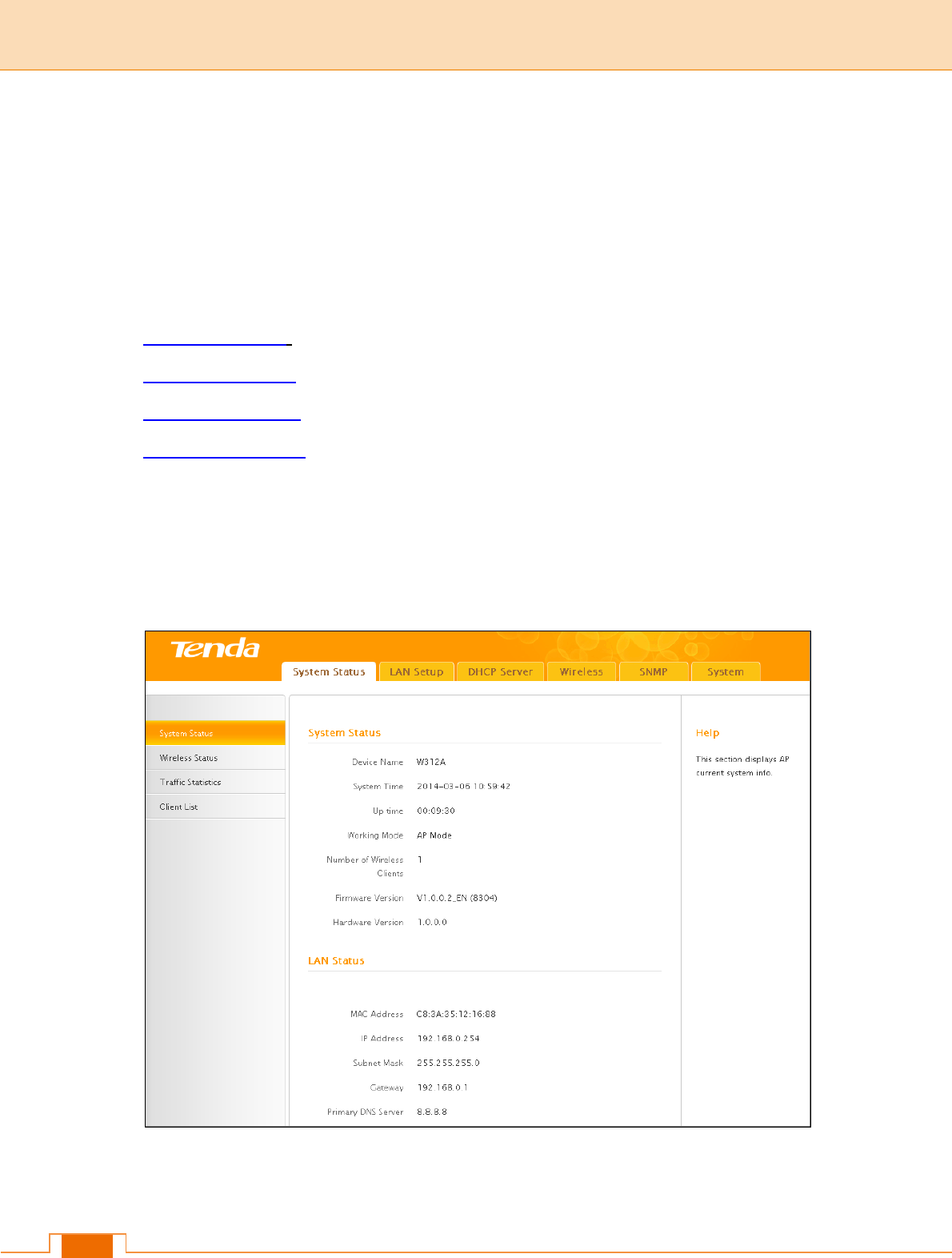
3) You will now enter the web configuration interface as seen below.
8
Ⅳ Features & Configurations
1 Status
This section includes the following:
1.1 System Status: View the device’s system information and LAN settings.
1.2 Wireless Status: View the device’s wireless information and current SSID settings.
1.3 Traffic Statistics: View current traffic statistics of each SSID.
1.4 Wireless Clients: View the MAC addresses and connection speed of the wireless
clients that currently connect to each SSID.
1.1 System Status
Here you can view the device’s system status and LAN status.
9
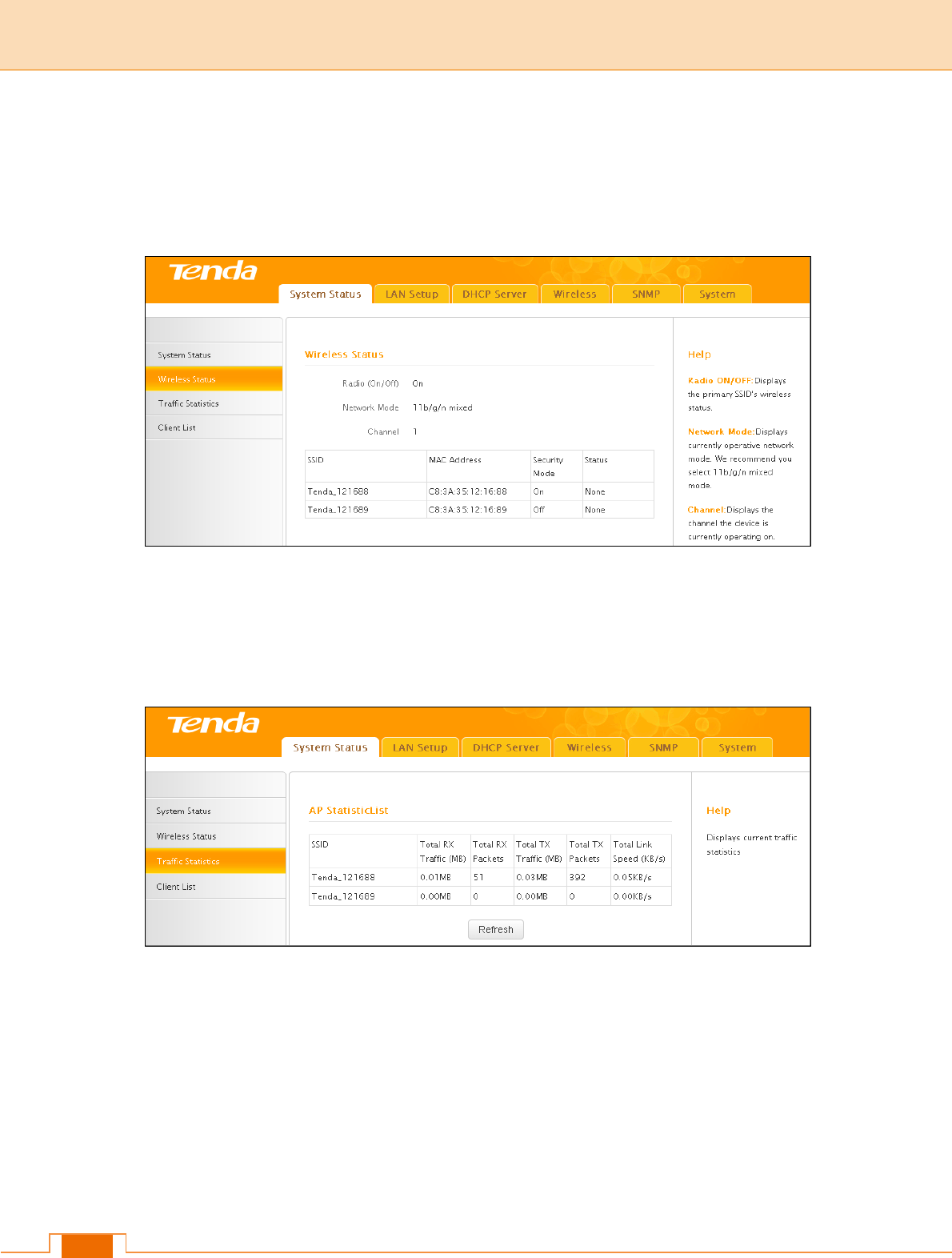
1.2 Wireless Status
Click Status -> Wireless Status and you can view the device’s wireless information and
current SSID settings.
1.3 Traffic Statistics
Click Status -> Traffic Statistics and you can view current traffic statistics of the device's
SSID.
10
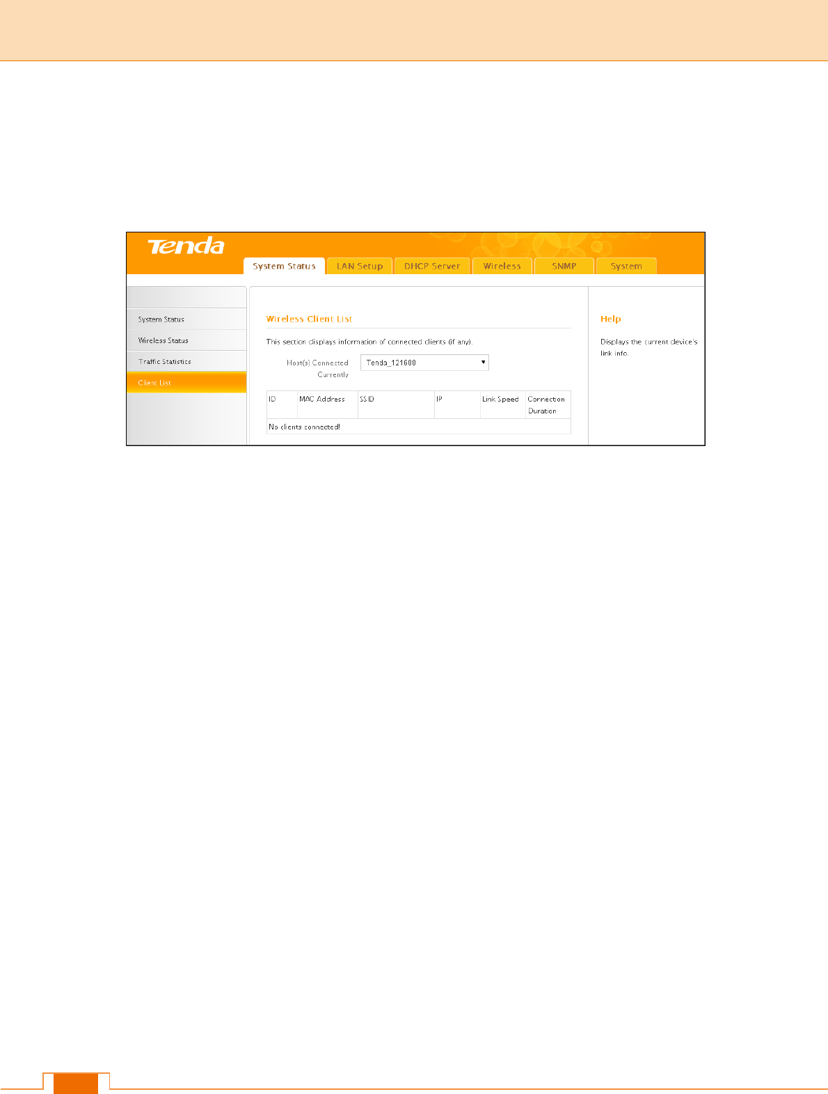
1.4 Wireless Clients
Here you can view the MAC addresses and connection speed of the wireless clients that
currently connect to each SSID.
To view wireless clients connected to a specific SSID, simply select it from the drop-down
list on the screen.
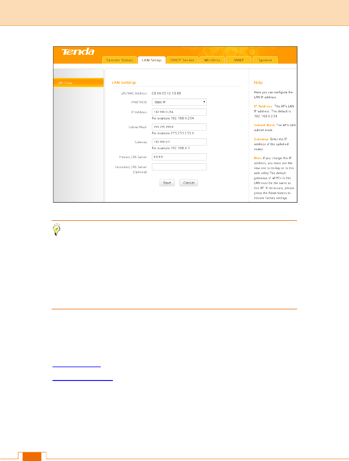
2 LAN Settings
Here you can configure the device's LAN IP address for Internet access. This IP address
is also to be used to access the device’s settings through a web browser. Most of the
default settings work in most cases. However, if your access point is part of a more
complex LAN network, then modify the settings to meet the requirements of your network
based on the explanation of the various fields.
Address Mode-Static IP: Manually specify the Static IP information (LAN IP address,
subnet mask, gateway, DNS server address) that corresponds with your existing
networking equipment.
Address Mode-Dynamic IP: Select it if you already have an active DHCP server on your
existing network. The wireless access point gets its IP address, subnet mask, and default
gateway settings automatically from the DHCP server on your network when you connect
the access point to your existing network.
11
Tip
1) Default IP address and subnet mask are respectively 192.168.0.254 and
255.255.255.0.
2) Be sure to make a note of any changes you apply to this page. If you change the LAN
IP address of this device, you have to update your PC’s TCP/IP settings and open a
new connection to the new IP address and then log in again.
3 DHCP Server
This section includes the following:
3.1 DHCP Server: Configure DHCP server settings.
3.2 DHCP Client List: View the information of the DHCP clients that currently obtain IP
addresses from the DHCP server.
3.1 DHCP Server
DHCP (Dynamic Host Configuration Protocol) assigns an IP address to each device on
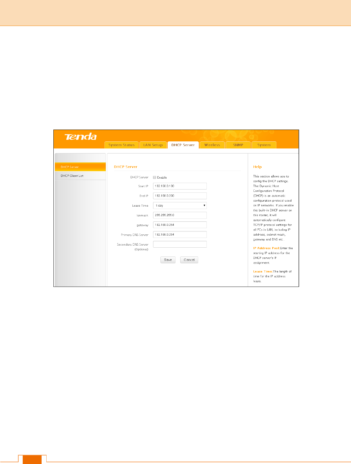
12
the LAN/private network. When you enable the DHCP Server, the DHCP Server will
automatically allocate an unused IP address from the IP address pool specified in this
screen to the requesting device as long as the device is set to "Obtain an IP Address
Automatically". If you disable this feature, you have to manually configure the TCP/IP
settings for all PCs on your LAN to access Internet.
Click DHCP Server to enter the configuration screen.
To set up the DHCP Server:
1) Enable the DHCP Server.
2) Specify the starting and ending address of the IP address pool. These addresses
should be part of the same IP segment as the remote Internet enabled device's LAN
IP Address.
3) Specify the lease time. It is a time length that the IP address is assigned to each
device before it is refreshed.
4) Specify the subnet mask. It should match the remote Internet enabled device's LAN
subnet.
5) Set the gateway address to the LAN IP address of the remote device.
6) Configure correct DNS settings. If a wrong DNS server address is entered, Web
13
pages may not be open.
Note
If there is already an active DHCP server on your network, make sure the IP address pool
you specified here is not a part of that existing DHCP server. Otherwise, IP collisions may
occur.
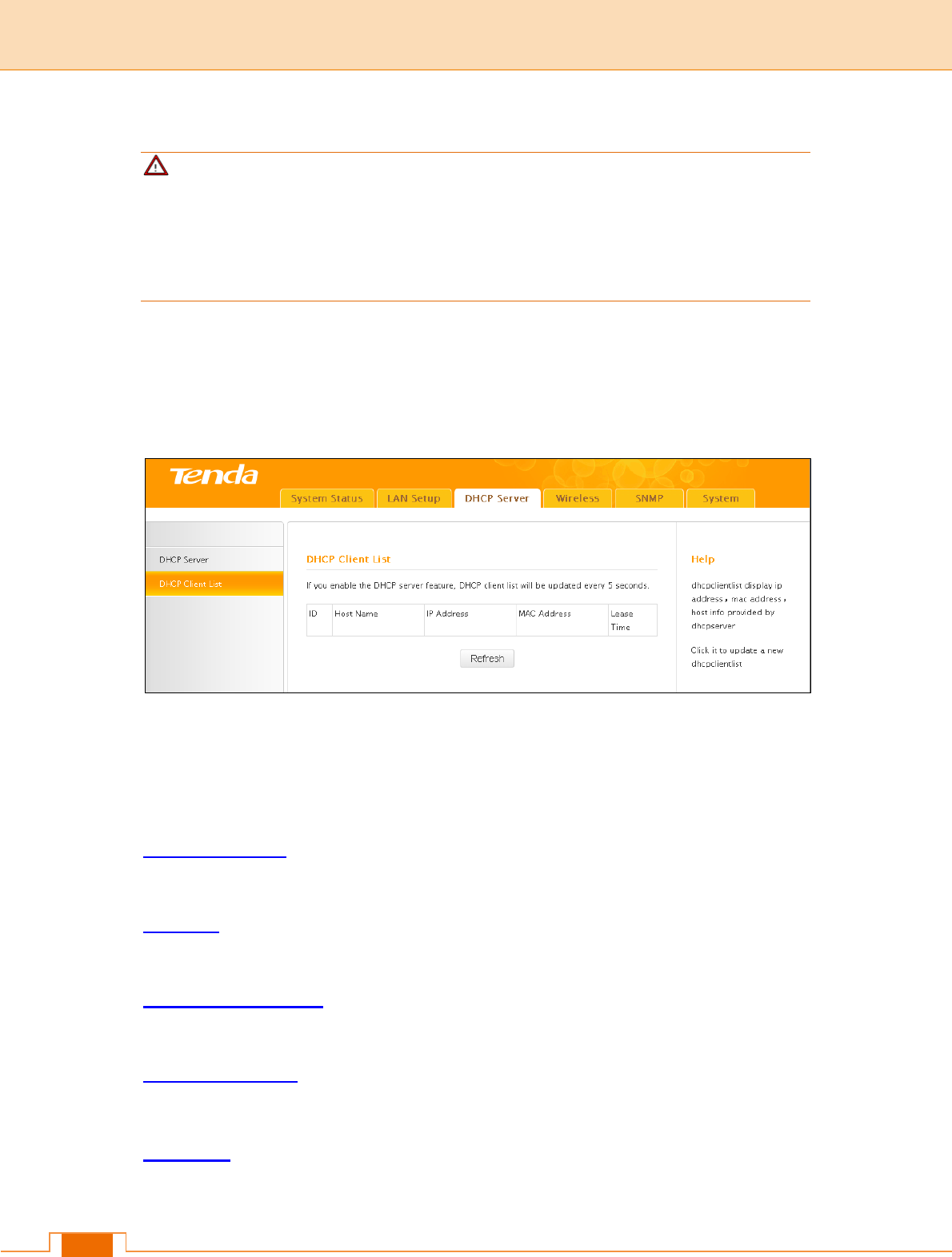
3.2 DHCP Client List
Click DHCP Server -> DHCP Client List to enter the DHCP clients screen. Here you can
view the host name, IP address, MAC address, and lease time information.
4 Wireless Settings
This section describes the following.
4.1 Basic Settings: Here you can configure the basic wireless settings of the device such
as the SSID (name of the network) and broadcast SSID, etc.
4.2 Radio: Here you can configure basic wireless settings including network mode and
channel, etc.
4.3 Advanced Settings: Here you can configure advanced wireless settings. This is only
recommended to advanced users.
4.4 Access Control: Specify a list of devices to allow or disallow a connection to your
wireless network via the device's MAC addresses.
4.5 QVLAN: Here you can configure the QVLAN feature to better manage wireless traffic
and enhance wireless security.
14
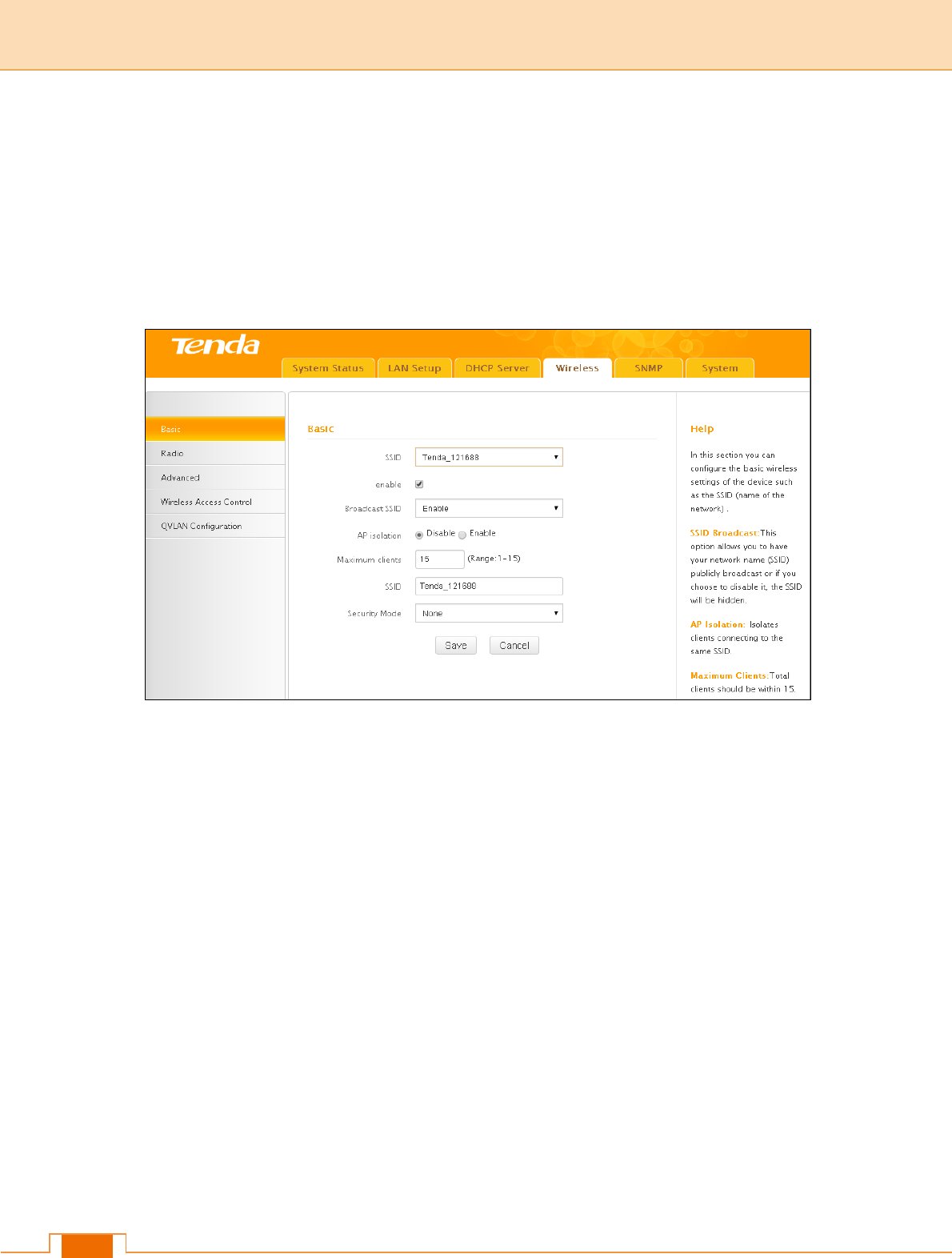
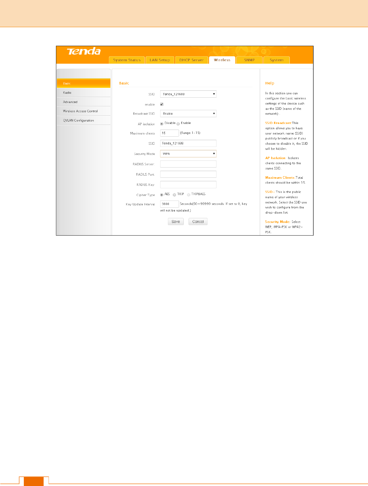
4.1 Basic Settings
Here you can configure the basic wireless settings of the device such as the SSID (name
of the network) and security.
Basic information
SSID: Select the SSID you wish to use. This is the public name of your wireless network.
Two SSIDs are supported.
Enable: Select whether to enable the selected SSID.
Broadcast SSID: This option allows you to have your network names (SSIDs) publicly
broadcast or if you choose to disable it, the SSIDs will be hidden. To join your hidden
wireless network, you must enter the SSID manually.
AP Isolation: Isolates clients connecting to this SSID.
Maximum Clients: Set the number of wireless clients that can join your wireless network.
When the number of wireless clients reaches the set value, new connections to this SSID
will be denied.
SSID: This field is configurable. You can change the current SSID.
Security Mode: Configure security settings for the current SSID. This device supports
WEP, WPA-PSK, WPA2-PSK, WPA/WPA2-PSK Mixed, WPA and WPA2 (To learn more,
15
read the following).
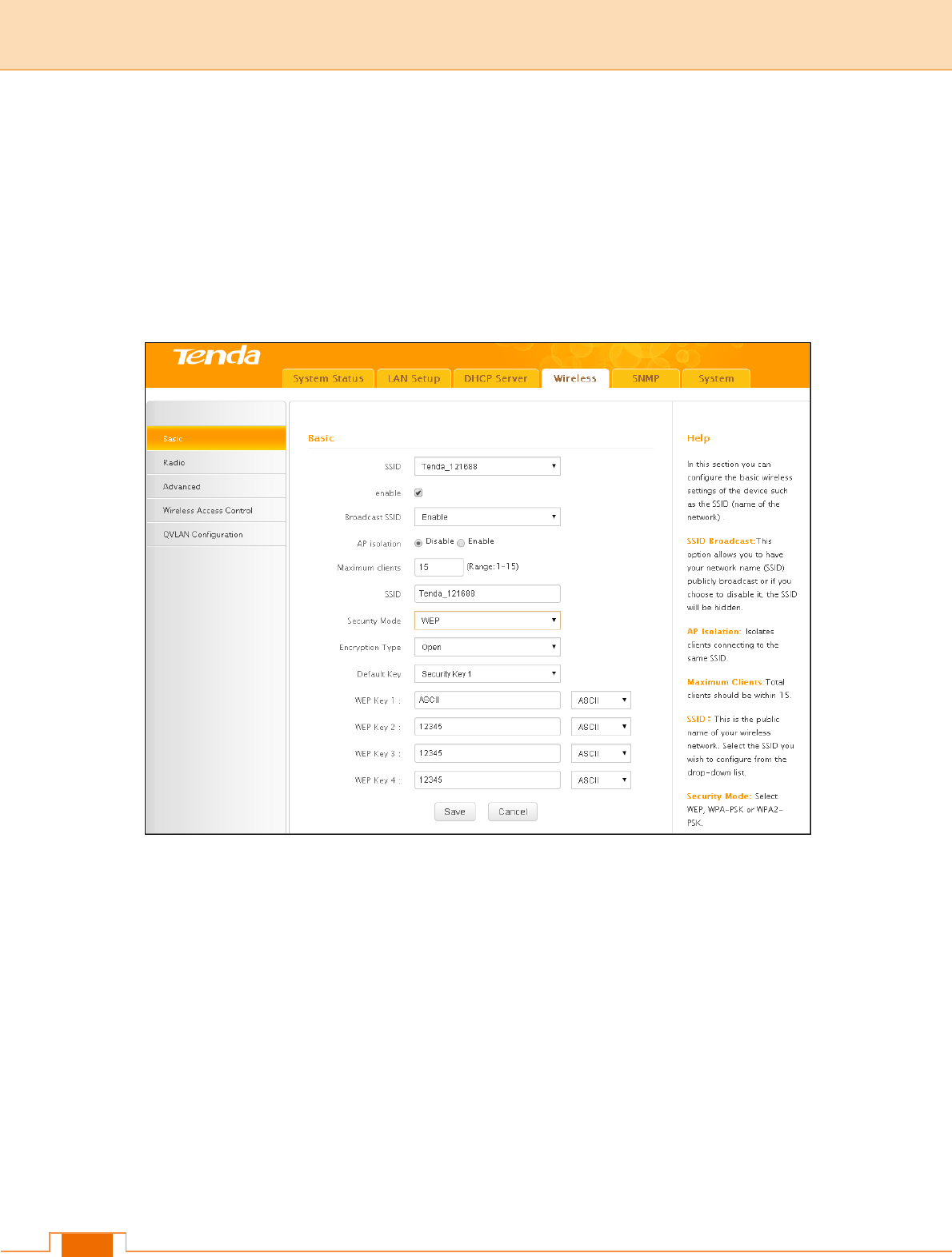
WEP
WEP (Wired Equivalent Privacy): WEP is a security algorithm for IEEE 802.11 wireless
networks. Introduced as part of the original 802.11 standard, its intention was to provide
data confidentiality comparable to that of a traditional wired network. Wireless speed can
reach up to 54Mbps if WEP is used.
Open, Shared and 802.1x are the same in encryption progression yet different in
authentication mode.
Open: Uses "no authentication" + WEP Encryption. Wireless clients can be associated
with the device without going through authentication. Only data in transmission is
encrypted with WEP encryption.
Shared: Uses shared key authentication + WEP Encryption. A WEP key that is mutually
agreed in advance is required from both sides while wireless clients try to associate with
the device. Association is established only if the two sides provide the same WEP key.
802.1x: Adopts802.1x identity authentication + WEP encryption mode. The supplicant (i.e.,
client device) is not allowed to access through the authenticator to the protected side of
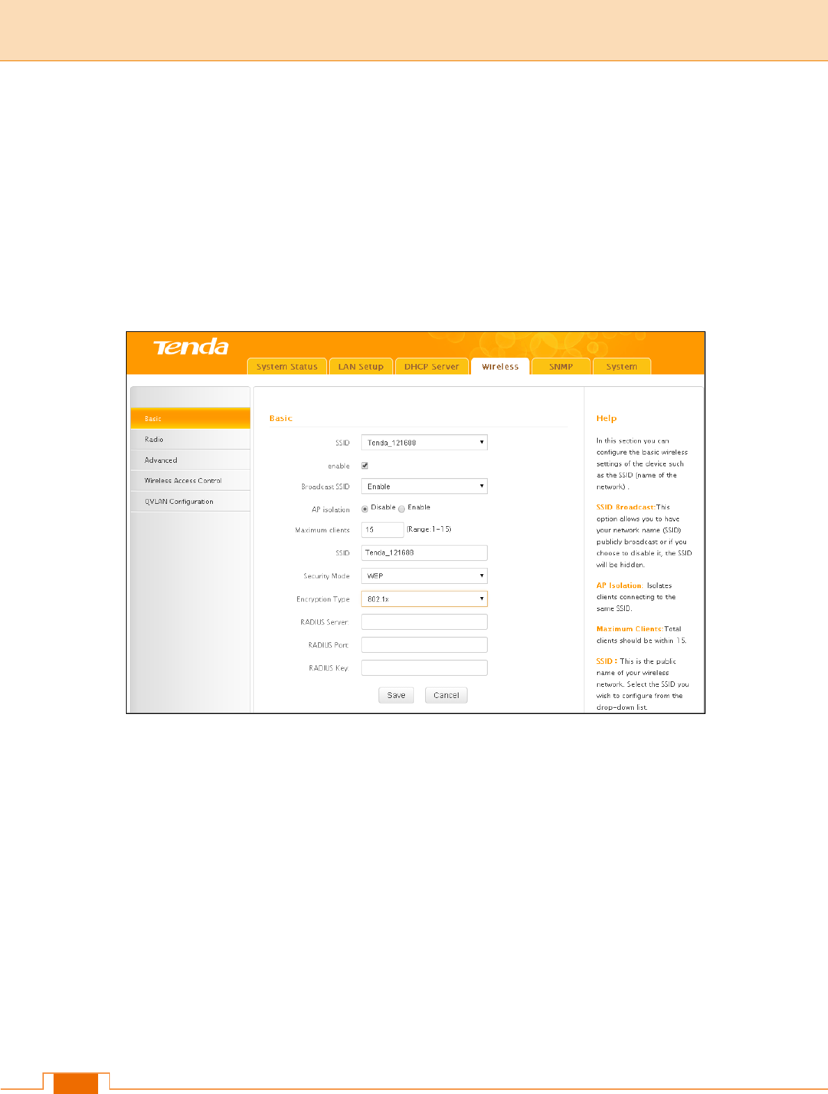
16
the network until the supplicant’s identity has been validated and authorized. If
authentication is successful, the authenticator sets the port to the "authorized" state and
normal traffic is allowed, if it is unsuccessful the port remains in the "unauthorized" state
and blocks traffic.
Default Key: Specify a WEP key from the preset keys for current use. For example, if you
select Key 2, wireless clients must join your wireless network using this Key 2.
WEP-802.1x Configuration Procedures:
SSID: This is the public name of your wireless network. Select the SSID you wish to
configure from the drop-down list.
Security Mode: Select WEP.
Encryption Mode: Select 802.1X.
Radius Server: Enter the IP address of Radius server on your LAN.
Radius Port: Enter the Authentication port for the Radius server on your LAN.
Radius Key: Enter the Authentication key for the Radius server.
WPA-PSK, WPA2-PSK
WPA: The WPA protocol implements the majority of the IEEE 802.11i standard. It
enhances data encryption through the Temporal Key Integrity Protocol (TKIP) which is a

17
128-bit per-packet key, meaning that it dynamically generates a new key for each packet.
WPA also includes a message integrity check feature to prevent data packets from being
tampered with. Only authorized network users can access the wireless network. WPA
adopts enhanced encryption algorithm over WEP.
WPA2: WPA2 is based on 802.11i and uses Advanced Encryption Standard (AES) instead
of TKIP. It is more secure than WPA and WEP.
Security Mode: Supports WPA-PSK, WPA2-PSK and WPA/WPA2-PSK Mixed.
WPA-PSK: Supports AES and TKIP cipher types.
WPA2-PSK: Supports AES, TKIP and TKIP+AES cipher types.
WPA/WPA2-PSK mixed: If selected, both WPA-PSK and WPA2-PSK secured wireless
clients can join your wireless network.
Cipher Type: Includes AES, TKIP and TKIP&AES.
AES: If selected, wireless speed can reach up to 300Mbps.
TKIP: If selected, wireless speed can reach up to 54Mbps.
TKIP+AES: If selected, both AES and TKIP secured wireless clients can join your wireless
network.
Key Update Interval: Enter a valid time period for the key to be changed.

18
Configuration Procedures:
1) SSID: This is the public name of your wireless network. Select the SSID you wish to
configure from the drop-down list.
2) Security Mode: Select WPA-PSK, WPA2-PSK or WPA/WPA2-PSK Mixed.
3) Cipher Type: Select the cipher type you wish to use.
4) Key: Enter a security key.
WPA, WPA2
The Wi-Fi Alliance defined the WPA/WPA2 in response to weaknesses found in WPA-PSK
or WPA2-PSK in key management. It uses 802.1x to authenticate users and generate a
root key for encrypting data instead of using a manually set pre-shared key.
With 802.1X authentication, the supplicant provides credentials, such as user
name/password or digital certificate, to the authenticator, and the authenticator forwards
the credentials to the authentication server for verification. If the authentication server
determines the credentials are valid, the supplicant (client device) is allowed to access
resources located on the protected side of the network. Data transmission over the
wireless network is encrypted with dynamic keys assigned by the Radius server, which
greatly enhances security. WPA/WPA2 becomes the most preferred security mode with its
offered better security.
19
Configuration Procedures:
1) SSID: This is the public name of your wireless network. Select the SSID you wish to
configure from the drop-down list.
2) Security Mode: Select WPA or WPA2.
3) RADIUS Server: Enter the IP address of Radius server on your LAN.
4) RADIUS Port: Enter the Authentication port for the Radius server on your LAN.
5) RADIUS Key: Enter the Authentication key for the Radius server.
6) Cipher Type: Select the cipher type you wish to use.
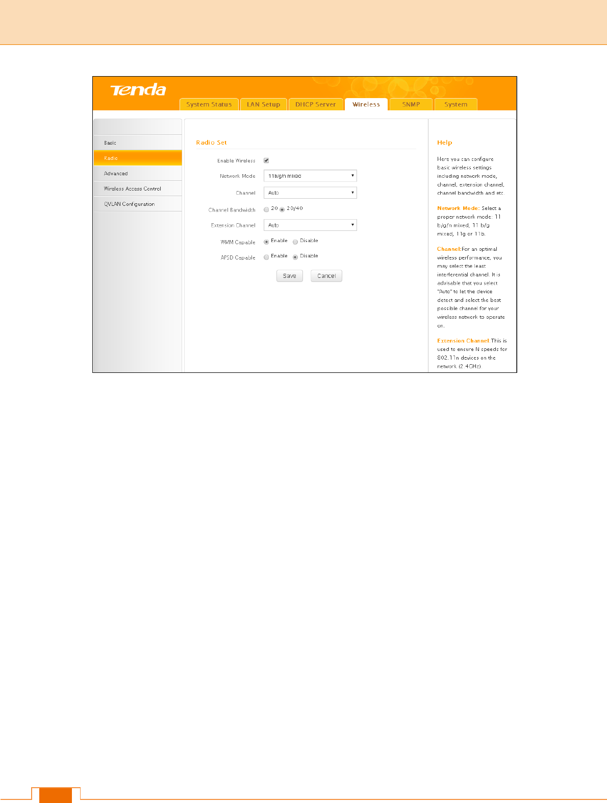
4.2 Radio
Click Wireless -> Radio to enter the configuration screen. Here you can configure basic
wireless settings including network mode, channel and etc.
20
Enable Wireless: Enable or disable the wireless feature.
Network Mode: Select a correct mode according to your wireless clients. The default is
11b/g/n mixed.
11b: This network mode delivers wireless speed up to 11Mbps and is only compatible with
11b wireless clients.
11g: This network mode delivers wireless speed up to 54Mbps and is only compatible with
11g wireless clients.
11b/g: This network mode delivers wireless speed up to 54Mbps and is compatible with
11b and 11g wireless clients.
11b/g/n mixed: This network mode delivers wireless speed up to 300Mbps and is
compatible with 11b/g/n wireless clients.
Channel: Select a channel or select Auto to let system automatically select one for your
wireless network to operate on if you are unsure. The best selection is a channel that is
the least used by neighboring networks.
Channel Bandwidth: Select a proper channel bandwidth to enhance wireless
performance. This option is available only in 802.11b/g/n. Wireless speed in the channel
bandwidth of 20/40 is 2 times in 20.
21
Extension Channel: This is used to ensure N speeds for 802.11n devices on the network.
This option is available in 11b/g/n mixed mode with channel bandwidth of 20/40.
WMM-Capable: WMM is QoS for your wireless network. Enabling this option may better
stream wireless multimedia data (such as video or audio).
ASPD Capable: Auto power saving mode. This option is effective only if WMM is enabled.
It is advisable to keep it disabled.
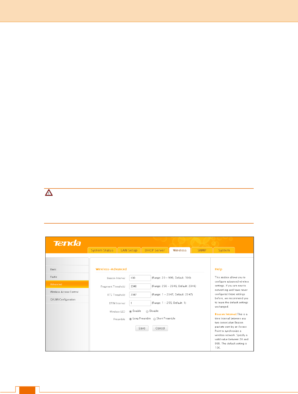
4.3 Advanced Settings
Here you can configure the advanced wireless settings including AP Isolation, Beacon
interval, Fragment threshold, RTS threshold and DTIM interval, etc, for your wireless
networks. Normally, the default settings will work. If not, change them according to the
suggestions given by your ISP or our technical staff. Click Wireless -> Advanced to enter
the configuration interface.
Note
Only change the default settings if instructed by your ISP or our technical staff. Wrong
configurations may degrade your wireless performance.
Beacon Interval: A time interval between any two consecutive Beacon packets sent by an
Access Point to synchronize a wireless network. The valid value range is between

22
20~999.
Fragment Threshold: Specify a Fragment Threshold value. Any wireless packet
exceeding the preset value will be divided into several fragments before transmission. The
valid value range is between 256~2346.
RTS Threshold: If a packet exceeds the set value, RTS/CTS scheme will be used to
reduce collisions. Set it to a smaller value provided that there are distant clients and
interference. For normal SOHO, it is recommended to keep the default value unchanged;
otherwise, device performance may be degraded. The valid value range is between
1~2347.
DTIM Interval: A DTIM (Delivery Traffic Indication Message) Interval is a countdown
informing clients of the next window for listening to broadcast and multicast messages.
When such packets arrive in the router’s buffer, the router will send DTIM (delivery traffic
indication message) and DTIM interval to alert clients of the receiving packets.
Wireless LED: Select to turn on or off the wireless LED.
Preamble: There are two types of preambles: long preamble and short preamble. The
preamble signals to the receiving node that data is incoming and indicates when the data
flow is about to begin. For wireless transmission, the longer the preamble is, the less the
data is. So support of a short preamble can boost the transmission efficiency of a wireless
interface. Support of short preamble is optional for 802.11b yet a must for 802.11g.
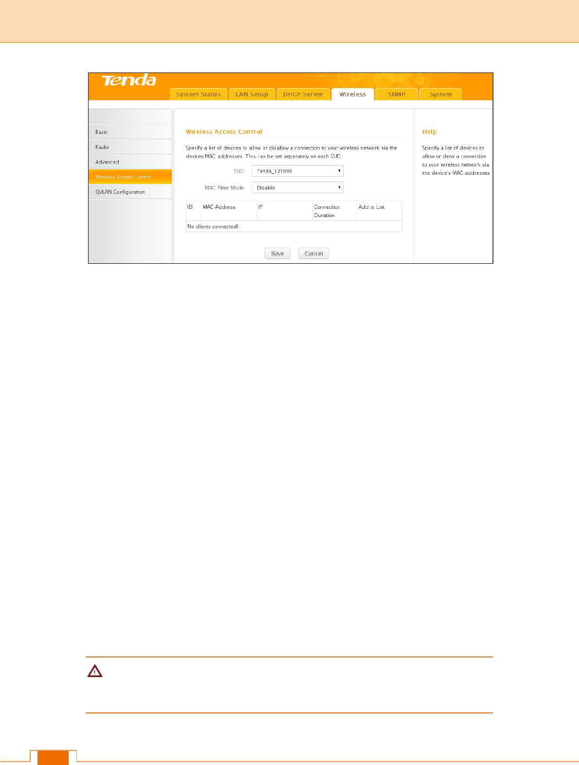
4.4 Access Control
Specify a list of devices to permit or forbid a connection to your wireless network via the
devices’ MAC Addresses. Click Wireless -> Access Control to enter the configuration
screen.
23
MAC Filter: There are three options available: Disable, Deny and Allow.
Disable: Disable the access control feature.
Allow: Allow only devices at specified MAC addresses to join your wireless network.
Deny: Blocks only devices at specified MAC addresses from joining your wireless
network.
Configuration Procedures:
1) SSID: This is the public name of your wireless network. Select the SSID you wish to
configure from the drop-down list.
2) MAC Filter Mode: Select a MAC filter mode from the drop-down list.
3) Enter the wireless MAC address you wish to restrict and click Add. (Also, you can
simply select a wireless MAC address from the MAC addresses displayed on this
page to quickly add it)
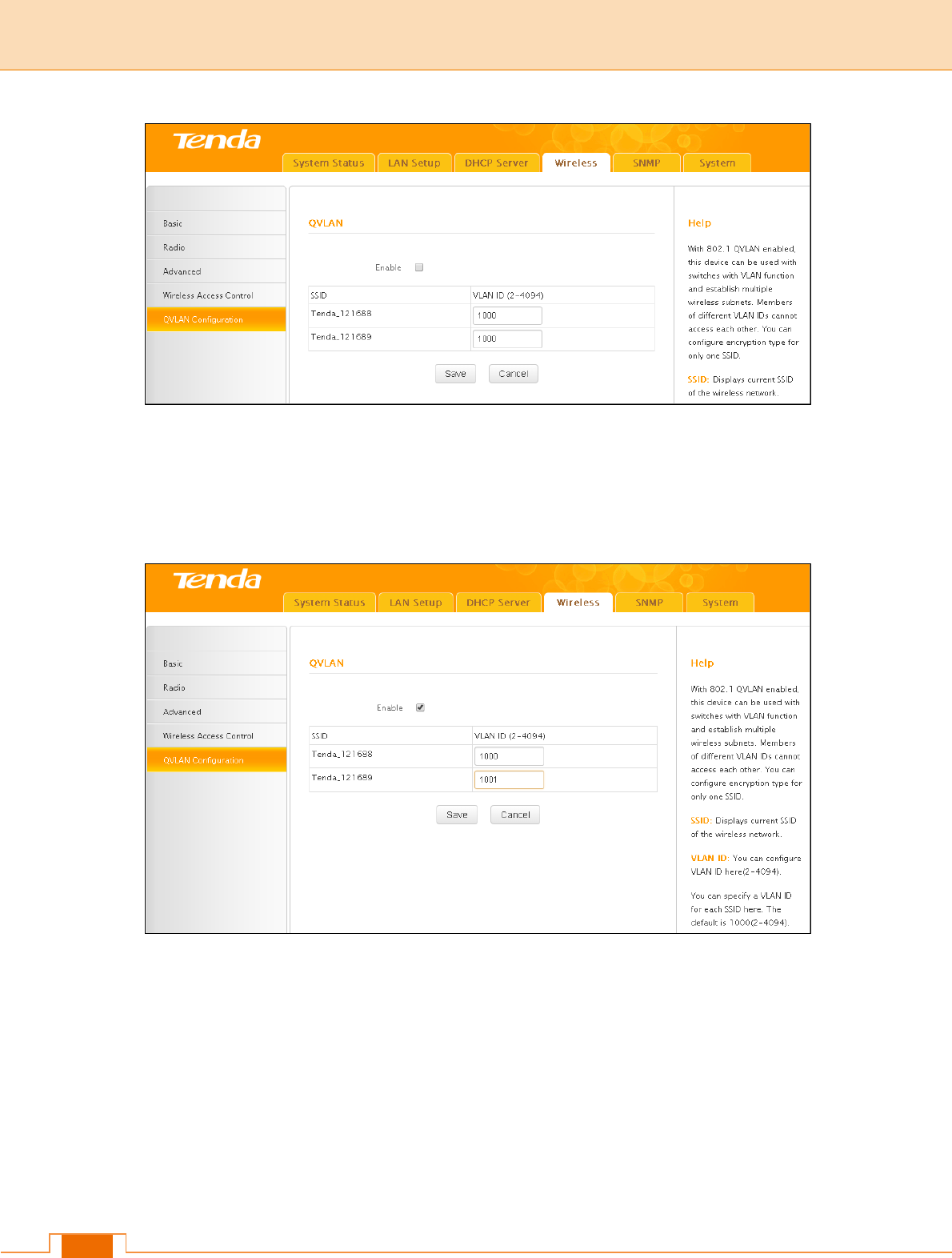
4.5 QVLAN
This device supports IEEE 802.1Q VLAN. With QVLAN enabled, this device can work
together with a VLAN capable switch to create multiple wireless subnets. Wireless
stations with different VLAN IDs will not be able to intercommunicate.
Note
When you enable QVLAN, only one SSID can be encrypted.
Click Wireless -> QVLAN Configuration to enter the configuration interface.
24
Configuration Procedures:
1) Check Enable.
2) Configure a VLAN ID for a corresponding SSID.
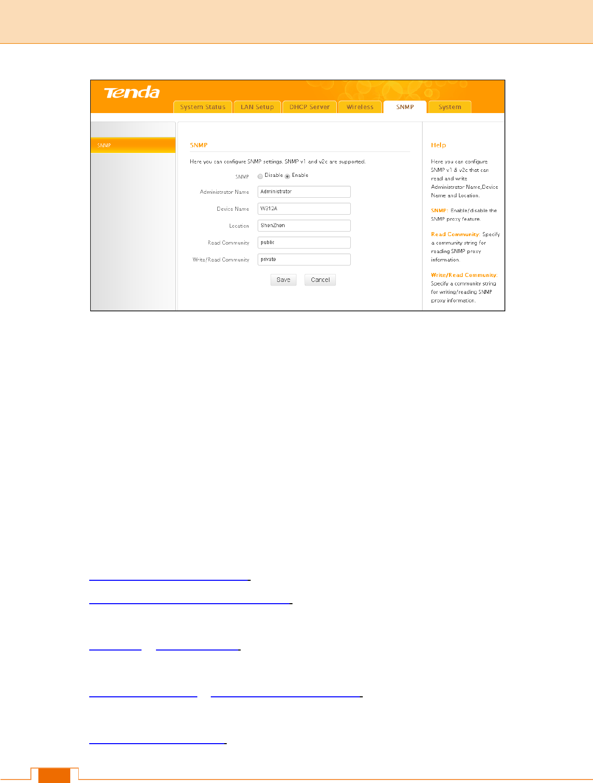
5 SNMP
This device can be managed from SNMP management utility. Click SNMP to enter the
configuration screen. Here you can configure the SNMP settings.
25
Configuration Procedures:
1) SNMP: Select Enable to enable the SNMP proxy feature.
2) Specify the Administrator Name, Device Name and Location.
3) Read Community: Specify a community string for SNMP management utility to read
the device's MIB information.
4) Write/Read Community: Specify a community string for SNMP management utility
to write/read the device's MIB information.
6 Tools
This section explains the following:
6.1 Firmware Upgrade & Reboot: Explains firmware upgrade and device reboot.
6.2 System Time & Login Timeout Setup: Explains how to set up system time and web
login timeout.
6.3 Syslog & 6.4 Log Settings: View the history of the device’s actions, log events and
simultaneously send them to the specified log server.
6.5 Backup & Restore & 6.6 Restore to Factory Default: Explains how to save, restore
configurations as well as restore factory defaults.
6.7 User Name & Password: Explains how to change login user name and password.
26
6.8 Diagnostics: Explains how to locate a network failure.
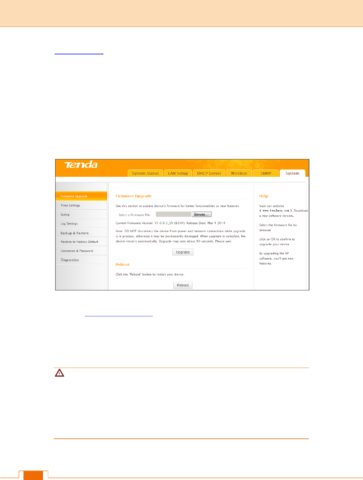
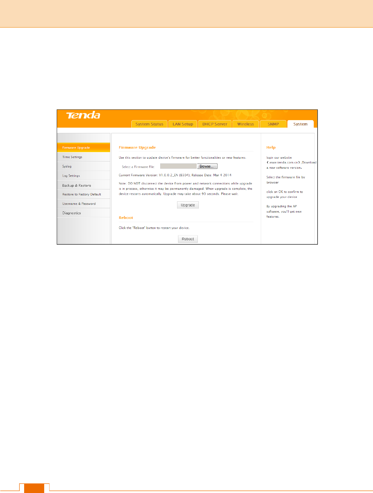
6.1 Firmware Upgrade & Reboot
Firmware Upgrade
Firmware upgrade is released periodically to improve the functionality of your device and
also to add new features. If you run into a problem with a specific feature of the device, log
on to Tenda website (http://www.tendacn.com) to download the latest firmware to update
your device.
To update firmware, do as follows:
1) Go to http://www.tendacn.com to download latest firmware.
2) Unzip the downloaded firmware and save it to your hard drive.
3) Click Browse to locate the firmware.
4) Click Upgrade and wait until the Progress Indicator bar shows 100% completed.
Note
Do NOT disconnect the device from power supply when uploading software to the device.
If the power supply is interrupted, the upload may fail, corrupt the software, and render the
device inoperable. When the upload completes, your wireless access point will
automatically restart. The upgrade process typically takes about several minutes.
To better experience stability or added features, restore the device to factory default
27
settings after upgrading firmware and then reconfigure it.
Reboot
For some settings to be effective, a reboot is required. All connections will be lost while
rebooting.
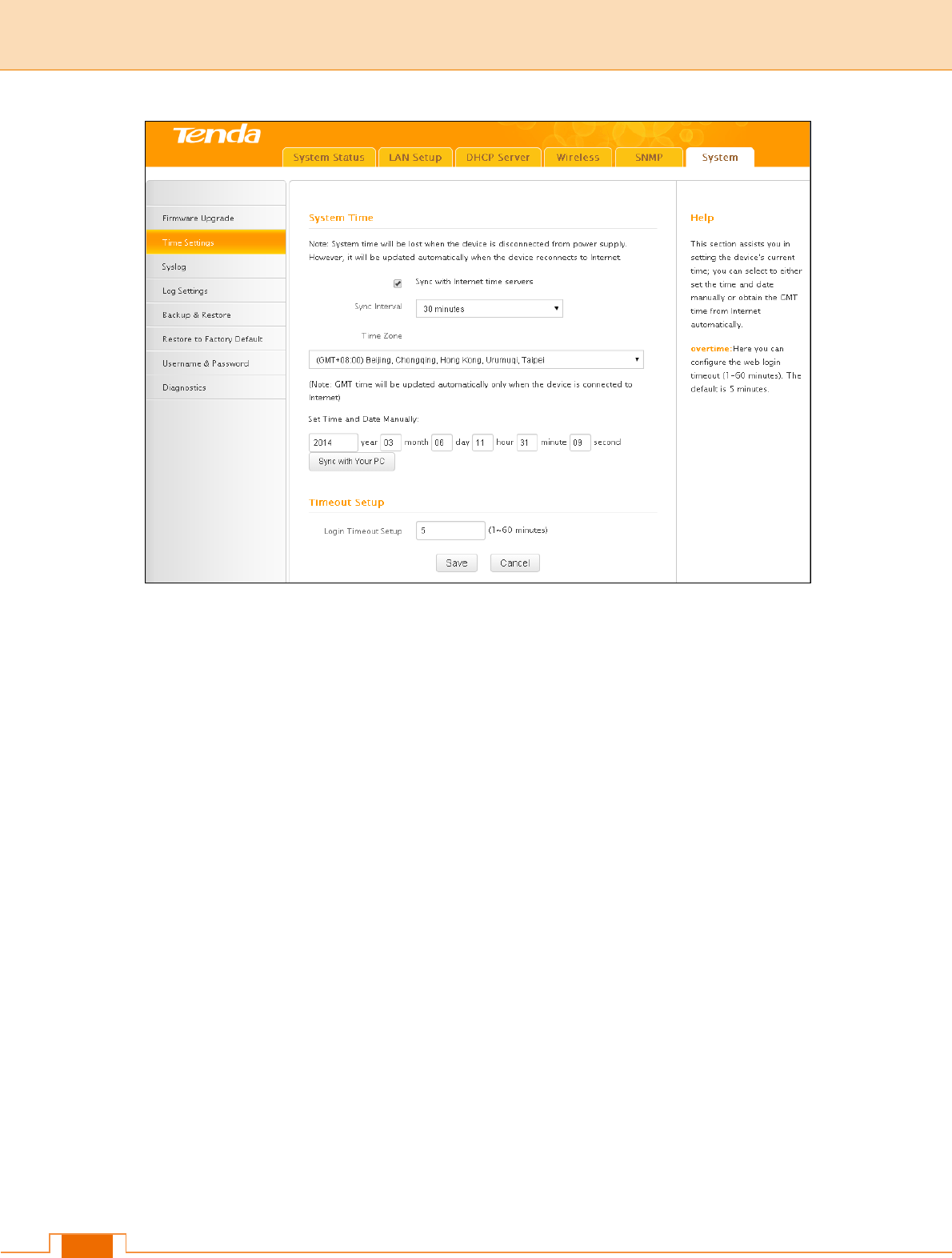
6.2 System Time & Login Timeout Setup
System Time
System can be configured using the following 2 methods:
Sync with Internet time servers: If enabled, system automatically connects to NTP
server on the Internet to synchronize the time.
Set Time and Date Manually/Sync with Your PC: Specify the time and date manually or
click Sync with Your PC to automatically copy your current PC's time to the device.
28
To Sync with Internet time servers:
1) Enable Sync with Internet time servers.
2) Select a Sync Interval from the drop-down list.
3) Select your time zone.
To set time and date manually:
1) Disable Sync with Internet time servers.
2) Specify the time and date manually or click Sync with Your PC to automatically copy
your PC's time to the device.
3) Go to Status to make sure the system time is correctly updated.
Web Login Timeout
Here you can set up the web Login Timeout. The device returns to login window
automatically depending on the specified login timeout and user name/password will be
required.
29
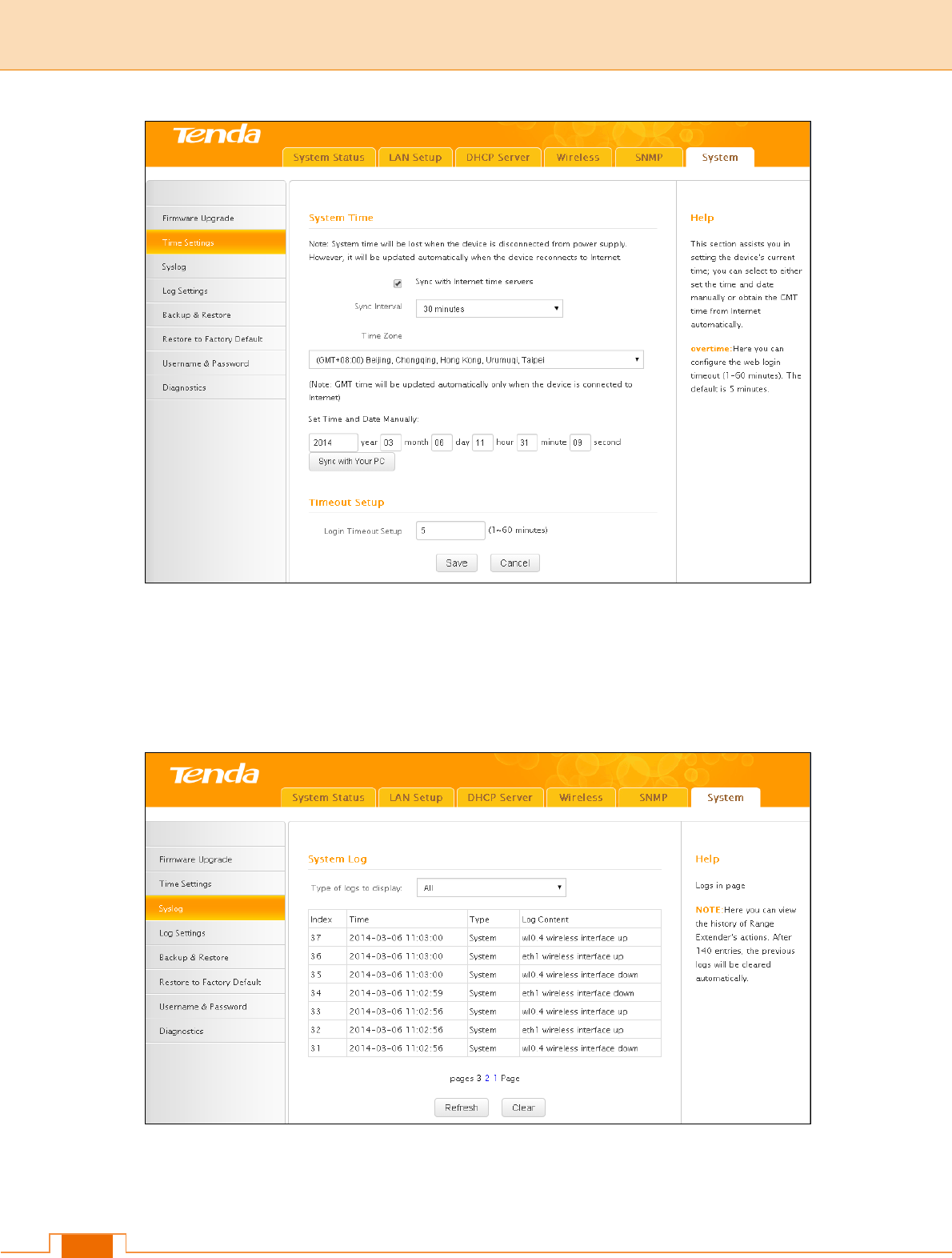
6.3 Syslog
View Logs
Here you can view the history of the device’s actions.
There are three types of logs are available: All, System and LAN. To view a specific type of
log, simply select it from the Type of logs to display drop-down list.
30
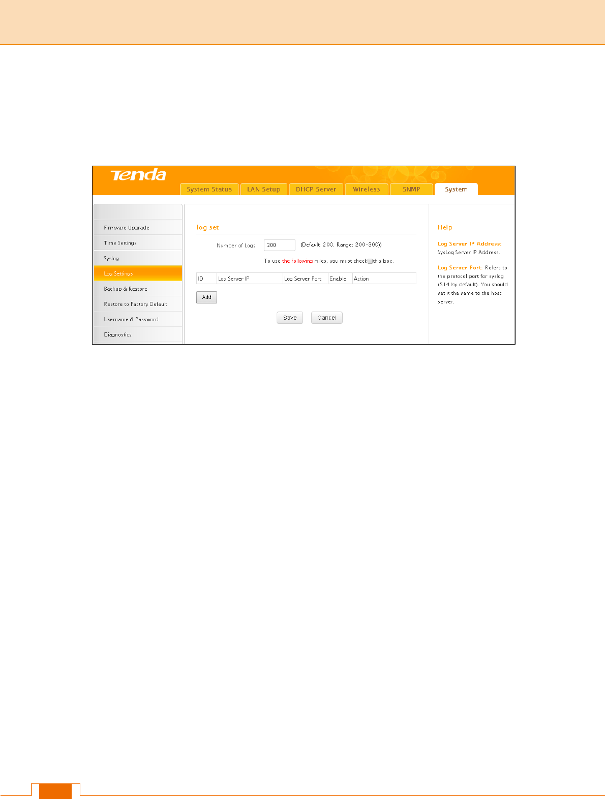
6.4 Log Settings
You can set the maximum number of logs that can be displayed and configure the log
server settings.
To configure the log server:
1) Click Add to add a log server.
2) Specify the IP address and port of the syslog server on your LAN and enable the log
server.
3) Check the "To use the following rules, you must check this box." option.
If configured successfully, the system will begin to log events and simultaneously send
them to the specified log server on your LAN. You can view all logs there.
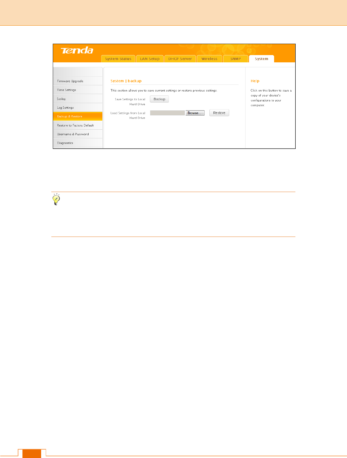
6.5 Backup & Restore
Once you have configured the device the way you want it, you can save these settings to
a configuration file on your local hard drive that can later be imported to your device in
case that the device is restored to factory default settings.
31
To back up configuration:
1) Click Backup.
2) Click Save on the File Download window and select a hard drive to save the file.
Tip
The default configuration file name is "APCfmfile.cfg". Do include the file name suffix of
".cfg" when renaming the file name to avoid problems.
To restore configuration:
1) Click Browse.
2) Select and load the configuration file that is saved previously to your local hard drive
and click the Restore button.
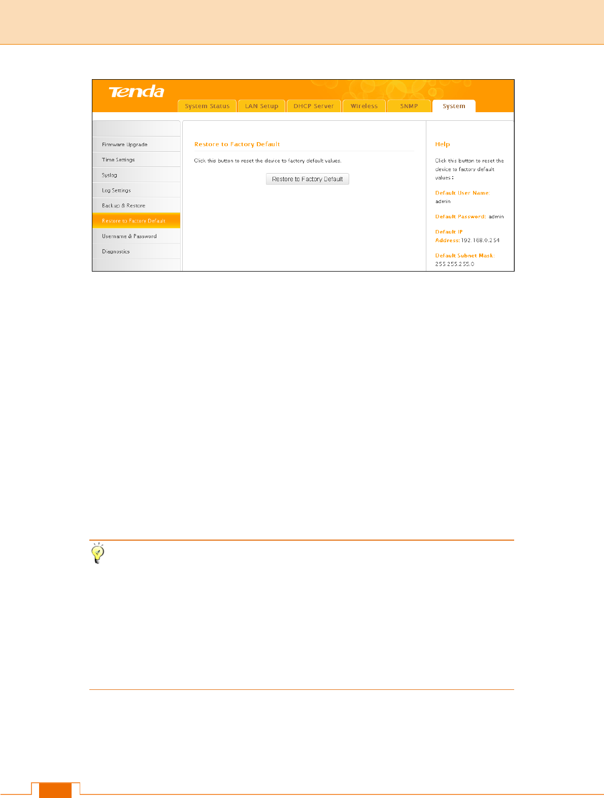
6.6 Restore to Factory Default
If the device or clients connected to the device fail to access the Internet due to incorrect
configurations and you cannot solve the problem, reset the device and then reconfigure it.
32
Method 1: To restore factory default using UI: Click the Restore to Factory Default
button and wait until the progress indicator displays 100% completed.
Method 2: To restore factory default by pressing the hardware reset button:
1) Remove the cover of the device.
2) Press the Reset button with a needle for about 7 seconds.
Factory Default Settings are listed below:
Default User Name: admin
Default Password: admin
Default LAN IP Address: 192.168.0. 254. This IP address is to be used to access the
device’s settings through a web browser.hg
Default LAN Subnet Mask: 255.255.255.0
Tip
1) The action of "restore factory default" removes all your configurations from the device.
So if you want to keep your configurations, do not perform this action.
2) Do not restore factory default settings unless the following happens:
You need to join a different network or unfortunately forget the login password.
You cannot access the Internet and Tenda technical staff asks you to reset the router.
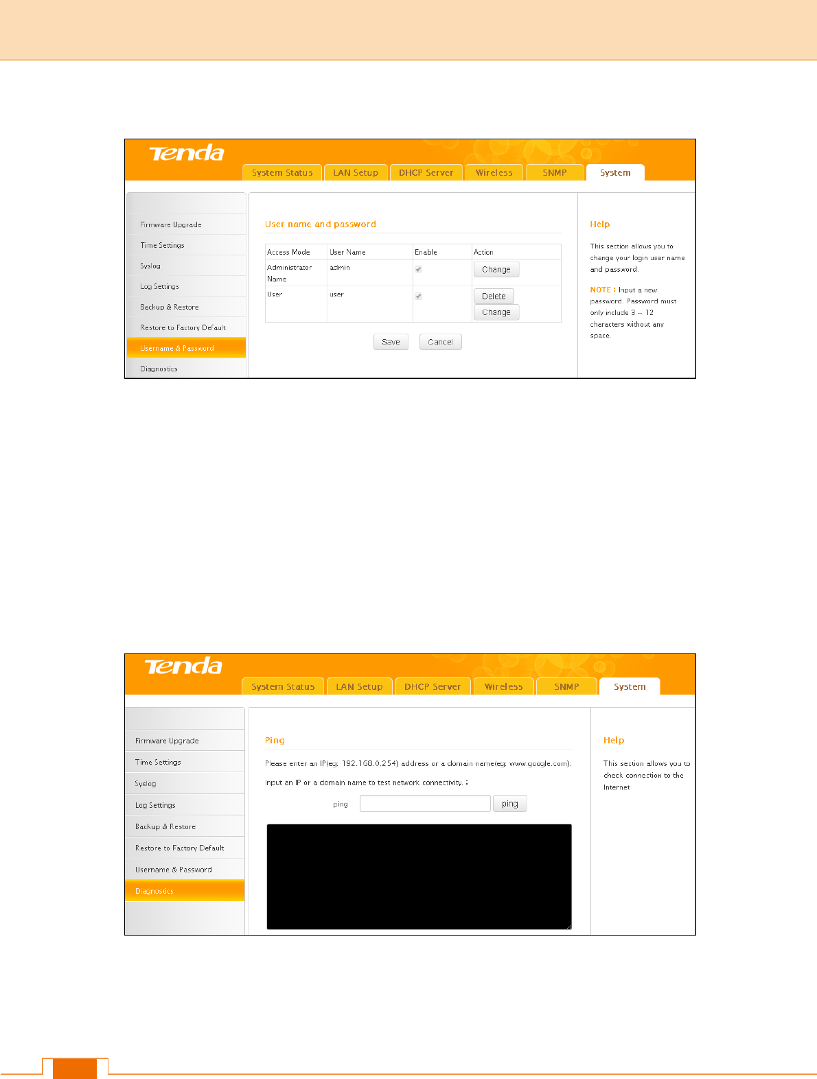
6.7 User Name & Password
Here you can change the user name and password for web login. We suggest that you
33
change the default password to a more secure password.
Administrator: If you log in to the device as an administrator, you have all available rights
to access the device.
User: If you log in to the device as a user, you can only view configurations instead of
configuring or changing any existing configurations.
6.8 Diagnostics
The device is capable of testing your connection. If your network is malfunctioning, use
the ping utility to test your network and find out where the problem is.
34
Ⅴ Appendix
1 Configure PC TCP/IP Settings
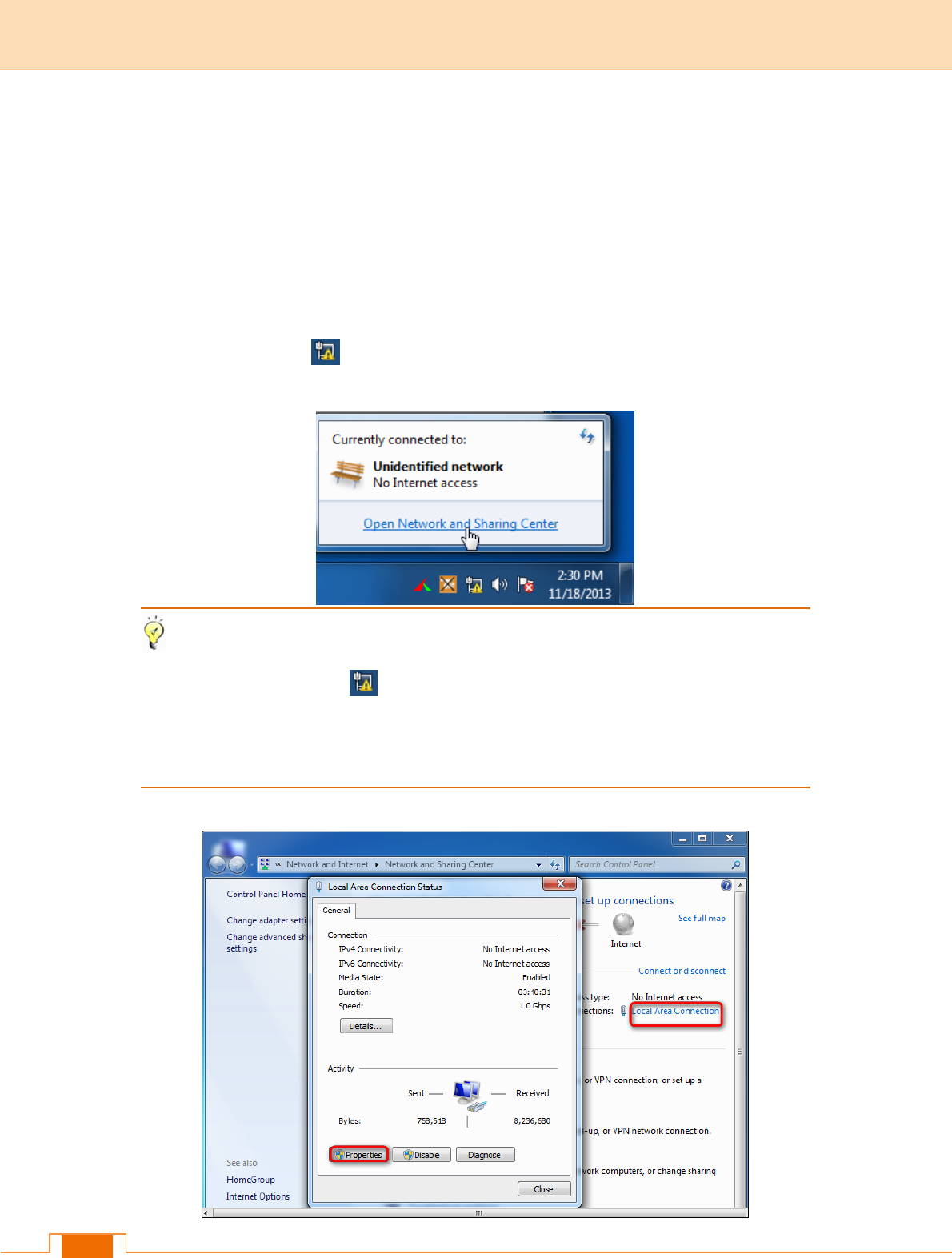
Windows 7
Step 1: Click the icon on the bottom right corner of your desktop.
Step 2: Click Open Network and Sharing Center.
Tip
If you cannot find the icon on the bottom right corner of your desktop, follow steps
below: Click Start -> Control Panel -> Network and Internet -> Network and Sharing
Center.
Step 3: Click Local Area Connection -> Properties.
35
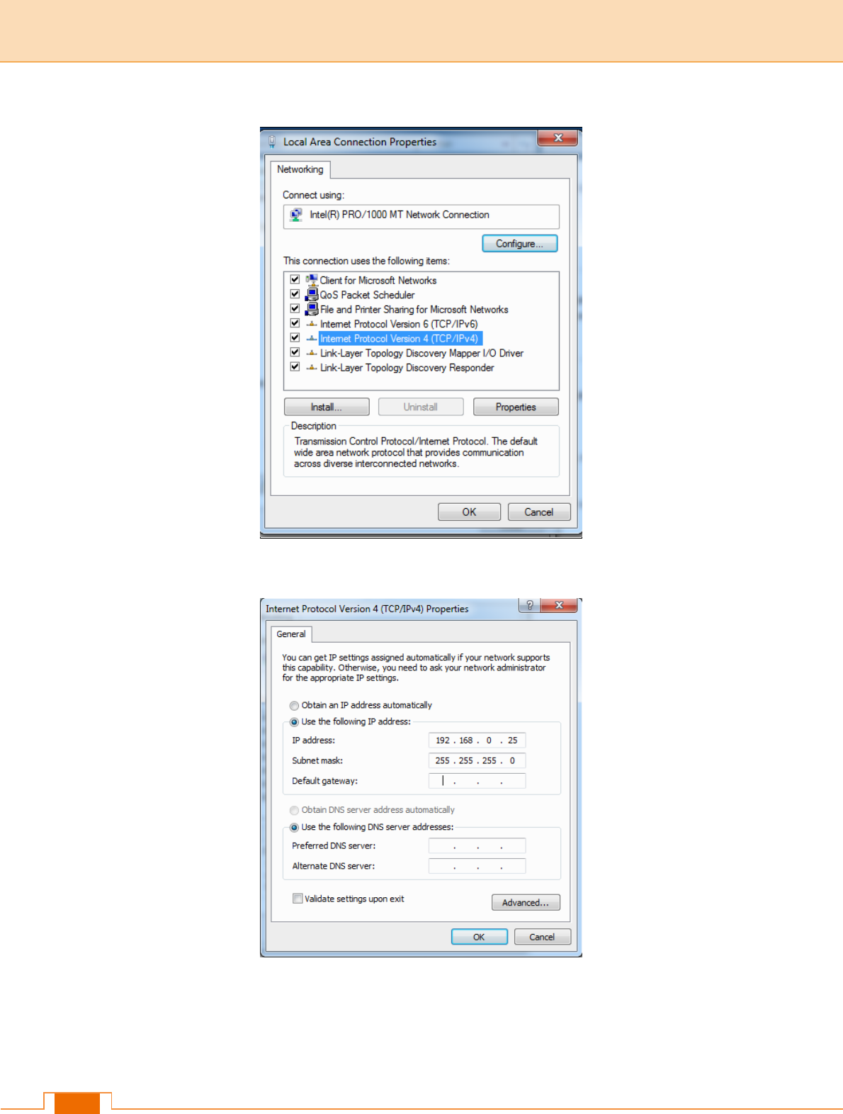
Step 4: Find and double click Internet Protocol Version 4(TCP/IPv4).
Step 5: Select Use the following IP address, IP address: 192.168.0.x (2~253); Subnet
mask: 255.255.255.0 and click OK.
Step 6: Click OK on the Local Area Connection Properties window (see Step 4 for the
screenshot).
36
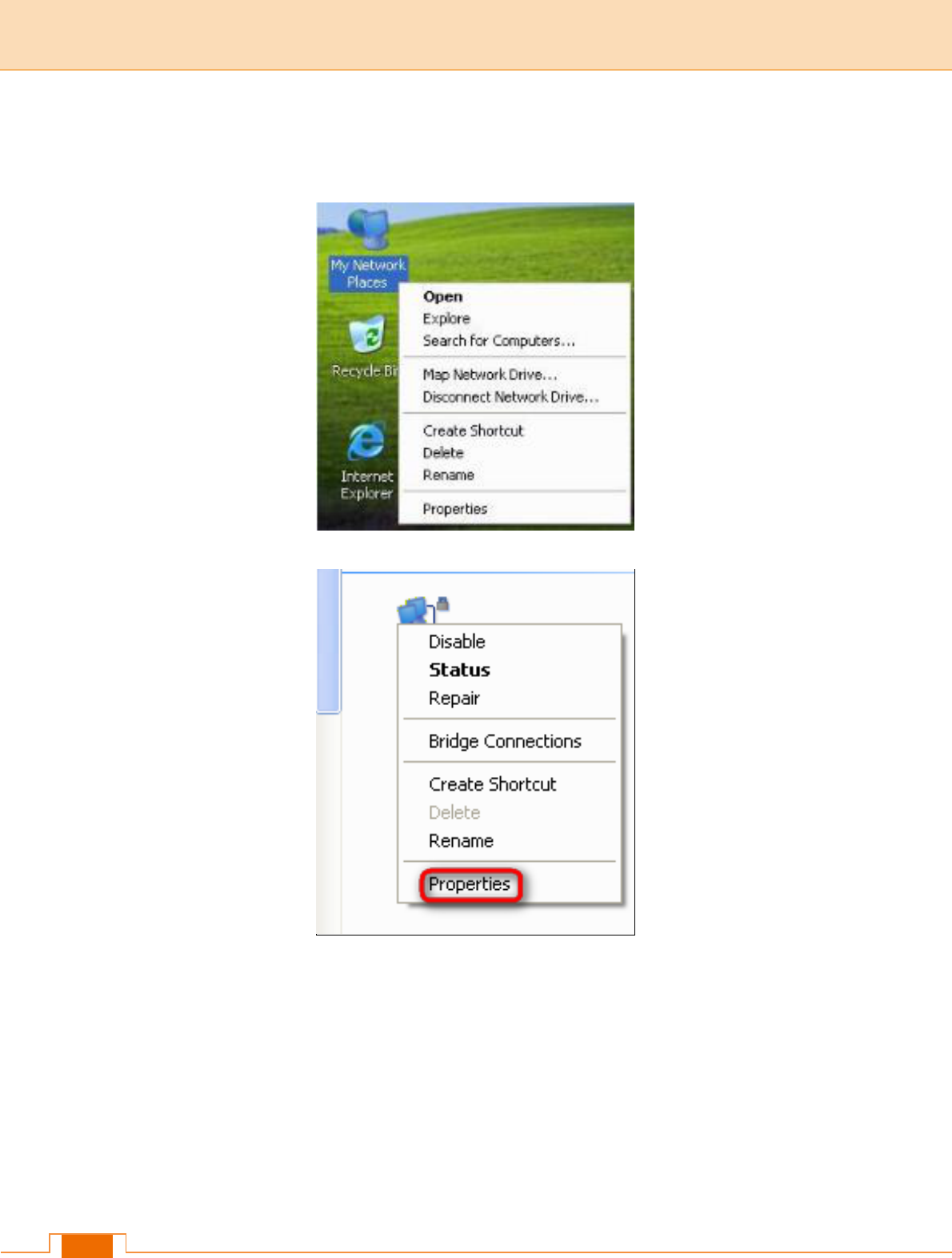
Windows XP
Step 1: Right click My Network Places on your desktop and select Properties.
Step 2: Right click Local Area Connection and select Properties.
Step 3: Scroll down to find and double click Internet Protocol (TCP/IP).
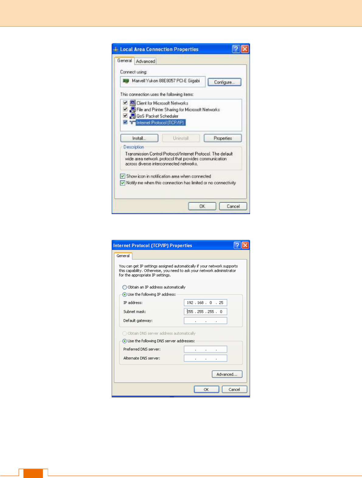
37
Step 4: Select Use the following IP address, IP address: 192.168.0.x (2~253); Subnet
mask: 255.255.255.0 and click OK.
Step 5: Click OK on the Local Area Connection Properties window (see Step 3 for the
screenshot).

38
2 Factory Default Settings
Item
Default Settings
Login
Login IP Address
192.168.0.254
Login User Name
admin
Login Password
admin
LAN Settings
(LAN)
IP Address
192.168.0.254
Subnet Mask
255.255.255.0
DHCP Server
Disabled
IP Pool
192.168.0.100~192.168.0.200
Wireless
Wireless
Enabled
Network Mode
11b/g/n mixed
Channel| Channel Bandwidth
Extension Channel
Auto|20/40|Auto
WMM
Enabled
APSD
Disabled
SSID
Primary SSID: Tenda_XXXXXX
Secondary SSID: Tenda_XXXXXY
(where “XXXXXX” is the last six characters of
the device's MAC address and Y = X+1.) You
can find the MAC address on the label
attached to the device.
SSID Status
Primary SSID: Enabled
Secondary SSID: Disabled
Broadcast SSID
Enabled
AP isolation
Disabled
Number of Clients
25
Beacon Interval
100ms
Fragment Threshold
2346

39
RTS Threshold
2347
DTIM Interval
1
Wireless LED On/Off
Enable
Preamble
Long Preamble
Wireless Security
Disabled
Wireless Access Control
Disabled
Tools
SNMP
Disabled
SNMP
Administrator Name: Administrator
Device Name: W312A
Location: Shenzhen
Read Community String: public
Write/Read Community String: private
System Time
Sync with Internet Time Servers
Time Zone: (GMT+08:00)Beijing, Chongqing,
Hong Kong, Urumqi
Web Login Timeout
5 minutes
Number of Logs
200
User Name & Password
Administrator: User Name | Password (admin
| admin)
User: User Name | Password (user | user)

40
3 Safety and Emission Statement
CE Mark Warning
This is a Class B product. In a domestic environment, this product may cause radio
interference, in which case the user may be required to take adequate measures. This
device complies with EU 1999/5/EC.
NOTE: (1) The manufacturer is not responsible for any radio or TV interference caused by
unauthorized modifications to this equipment. (2) To avoid unnecessary radiation
interference, it is recommended to use a shielded RJ45 cable.
FCC Statement
This device complies with Part 15 of the FCC Rules. Operation is subject to the following
two conditions: (1) This device may not cause harmful interference, and (2) this device
must accept any interference received, including interference that may cause undesired
operation.
This equipment has been tested and found to comply with the limits for a Class B digital
device, pursuant to Part 15 of the FCC Rules. These limits are designed to provide
reasonable protection against harmful interference in a residential installation. This
equipment generates, uses and can radiate radio frequency energy and, if not installed
and used in accordance with the instructions, may cause harmful interference to radio
communications. However, there is no guarantee that interference will not occur in a
particular installation. If this equipment does cause harmful interference to radio or
television reception, which can be determined by turning the equipment off and on, the
user is encouraged to try to correct the interference by one of the following measures:
- Reorient or relocate the receiving antenna.
- Increase the separation between the equipment and receiver.

41
- Connect the equipment into an outlet on a circuit different from that to which the
receiver is connected.
- Consult the dealer or an experienced radio/TV technician for help.
FCC Caution: Any changes or modifications not expressly approved by the party
responsible for compliance could void the user's authority to operate this equipment.
This transmitter must not be co-located or operating in conjunction with any other antenna
or transmitter.
The manufacturer is not responsible for any radio or TV interference caused by
unauthorized modifications to this equipment.
Radiation Exposure Statement
This equipment complies with FCC radiation exposure limits set forth for an uncontrolled
environment. This equipment should be installed and operated with minimum distance
20cm between the radiator & your body.
NOTE: (1) The manufacturer is not responsible for any radio or TV interference caused by
unauthorized modifications to this equipment. (2) To avoid unnecessary radiation
interference, it is recommended to use a shielded RJ45 cable.
NCC Notice
經型式認證合格之低功率射頻電機,非經許可,公司、商號或使用者均不得擅自變更頻率、
加大功率或變更設計之特性及功能。
低功率射頻電機之作用不得影響飛航安全及幹擾合法通信;經發現有幹擾現象時,應立即
停用,並改善至無幹擾時方得繼續使用。前項合法通信,指依電信規定作業之無線電信。
低功率射頻電機須忍受合法通信或工業、科學及醫療用電波輻射性電機設備之幹擾。