TES ELECTRONIC SOLUTIONS 9008251 Base Station User Manual INSTALLATION INSTRUCTIONS
TES ELECTRONIC SOLUTIONS Base Station INSTALLATION INSTRUCTIONS
Contents
- 1. USERS MANUAL
- 2. Installation Instructions
Installation Instructions
Final Draft
3M Building and Commercial Services Division
Communications Business
St Paul, MN 55144 ©3M 2008. All Rights Reserved
90-0024-0085-2
Digital Range Extender
78-6911-4961-7
Installation Instructions
PURPOSE
To "fill in" areas of poor radio coverage due to blockage of the RF signal by large metal objects and to extend
working distance from the digital system base station.
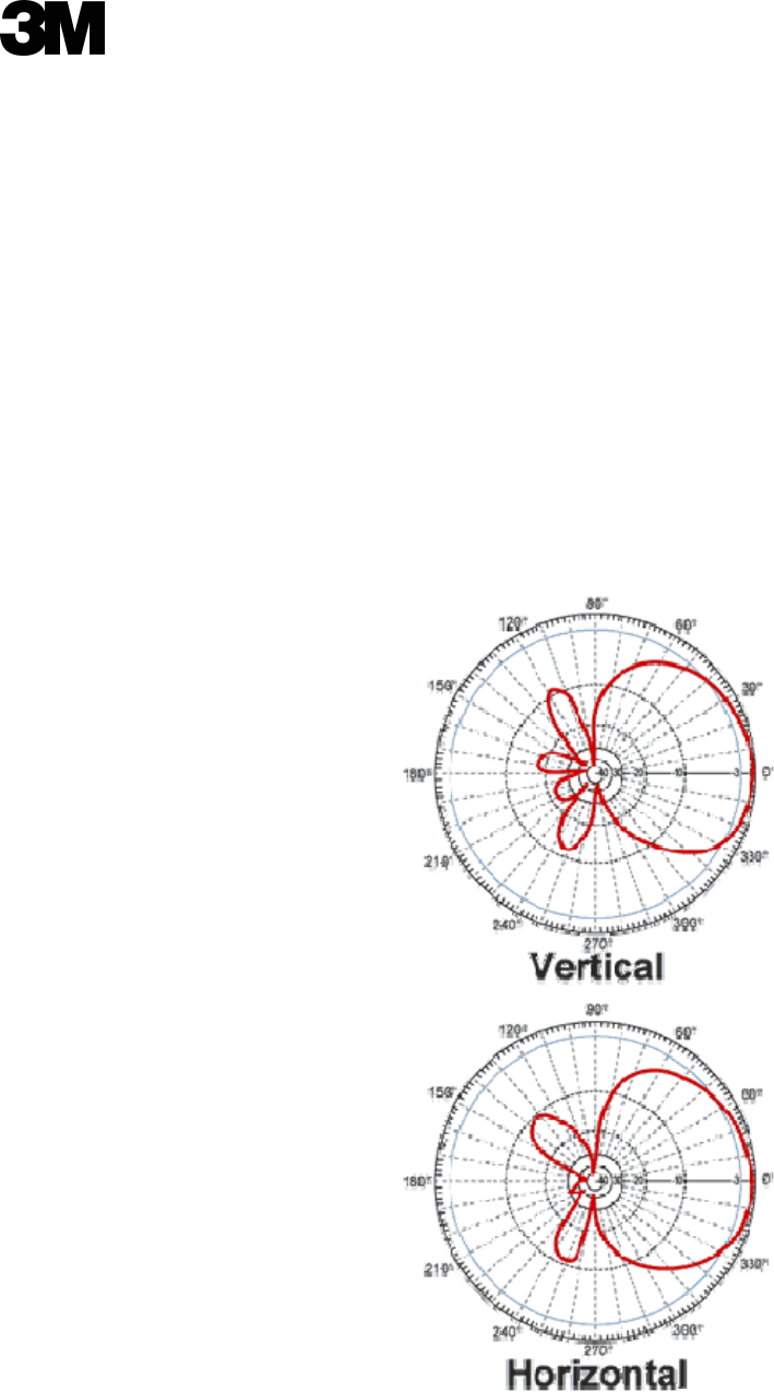
Radiation Pattern
The Digital Range Extender is not an omni-directional antenna similar to 3M’s previous Signal Enhancer; it is
more directional. The attached diagram shows its Radiation Pattern.
Final Draft
3M Building and Commercial Services Division
Communications Business
St Paul, MN 55144 ©3M 2008. All Rights Reserved
90-0024-0085-2
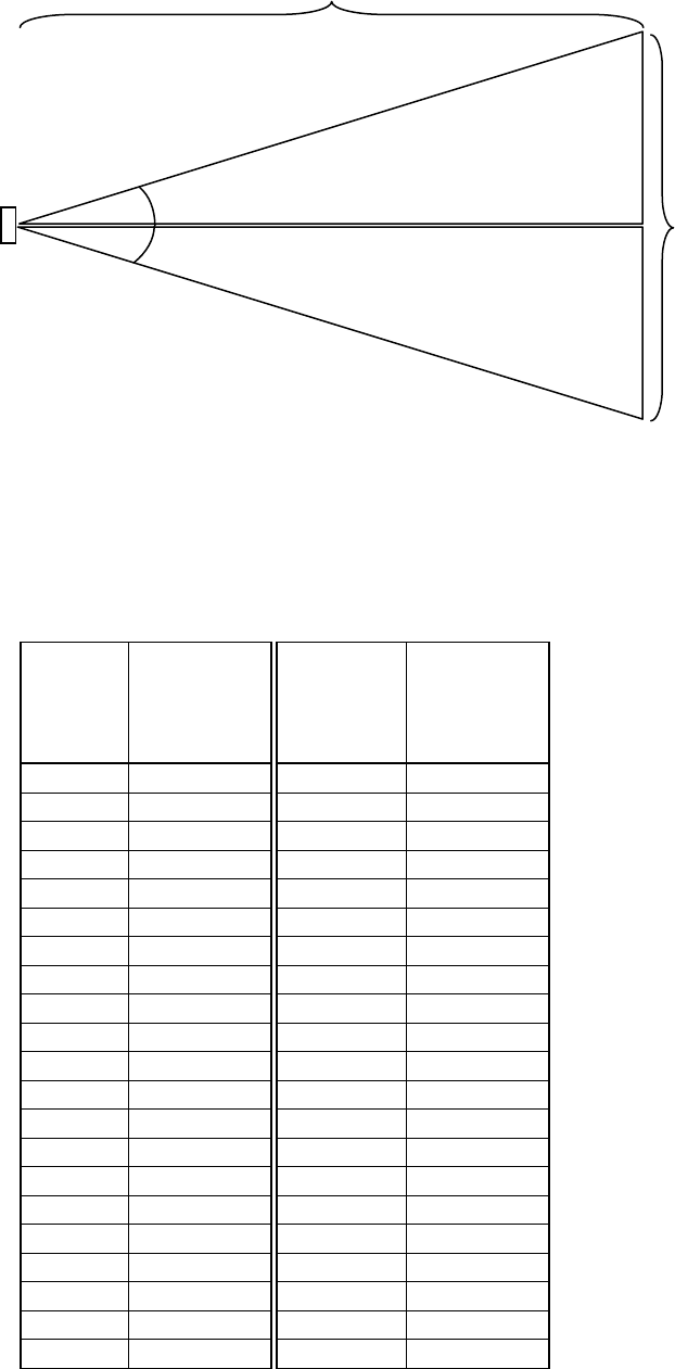
Distance From Antenna
Angle:37.5˚
Width Of Radio Coverag
e
Angle:37.5˚
HORIZONTAL BEAM WIDTH (Width)
Width Of Radio Coverage =2 * Distance From Antenna * (tan 37.5˚) or 1.53 * Distance From Antenna
Distance
From
Antenna
(feet)
Width Of
Radio
Coverage
(feet)
Distance
From
Antenna
(meters)
Width Of
Radio
Coverage
(meters)
3 4.6 0.9 1.4
4 6.1 1.2 1.9
5 7.7 1.5 2.3
6 9.2 1.8 2.8
7 10.7 2.1 3.3
8 12.2 2.4 3.7
9 13.8 2.7 4.2
10 15.3 3.0 4.7
11 16.8 3.4 5.1
12 18.4 3.7 5.6
13 19.9 4.0 6.1
14 21.4 4.3 6.5
15 23.0 4.6 7.0
16 24.5 4.9 7.5
17 26.0 5.2 7.9
18 27.5 5.5 8.4
19 29.1 5.8 8.9
20 30.6 6.1 9.3
21 32.1 6.4 9.8
22 33.7 6.7 10.3
23 35.2 7.0 10.7

Final Draft
3M Building and Commercial Services Division
Communications Business
St Paul, MN 55144 ©3M 2008. All Rights Reserved
90-0024-0085-2
24 36.7 7.3 11.2
25 38.3 7.6 11.7
26 39.8 7.9 12.1
27 41.3 8.2 12.6
28 42.8 8.5 13.1
29 44.4 8.8 13.5
30 45.9 9.1 14.0
31 47.4 9.5 14.5
32 49.0 9.8 14.9
33 50.5 10.1 15.4
34 52.0 10.4 15.9
35 53.6 10.7 16.3
36 55.1 11.0 16.8
37 56.6 11.3 17.3
38 58.1 11.6 17.7
39 59.7 11.9 18.2
40 61.2 12.2 18.7
41 62.7 12.5 19.1
42 64.3 12.8 19.6
43 65.8 13.1 20.1
44 67.3 13.4 20.5
45 68.9 13.7 21.0
46 70.4 14.0 21.5
47 71.9 14.3 21.9
48 73.4 14.6 22.4
49 75.0 14.9 22.9
50 76.5 15.2 23.3
Final Draft
3M Building and Commercial Services Division
Communications Business
St Paul, MN 55144 ©3M 2008. All Rights Reserved
90-0024-0085-2
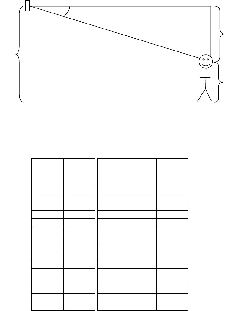
Minimum Distance
Angle:32.5˚
Height
Antenna
Height
Person Height:
4 feet
1.2 meters
VERTICAL BEAM WIDTH (Height)
Minimum Distance = (Height - Person Height) / (tan 32.5˚) or 1.57 * (Height - Person Height)
Antenna
Height
(feet)
Minimum
Distance
(feet)
Antenna Height
(meters)
Minimum
Distance
(meters)
6 3.1 1.8 1.0
7 4.7 2.1 1.4
8 6.3 2.4 1.9
9 7.9 2.7 2.4
10 9.4 3.0 2.9
11 11.0 3.4 3.3
12 12.6 3.7 3.8
13 14.1 4.0 4.3
14 15.7 4.3 4.8
15 17.3 4.6 5.3
16 18.8 4.9 5.7
17 20.4 5.2 6.2
18 22.0 5.5 6.7
19 23.6 5.8 7.2
20 25.1 6.1 7.7
Final Draft
3M Building and Commercial Services Division
Communications Business
St Paul, MN 55144 ©3M 2008. All Rights Reserved
90-0024-0085-2
How to determine the proper location of the antenna
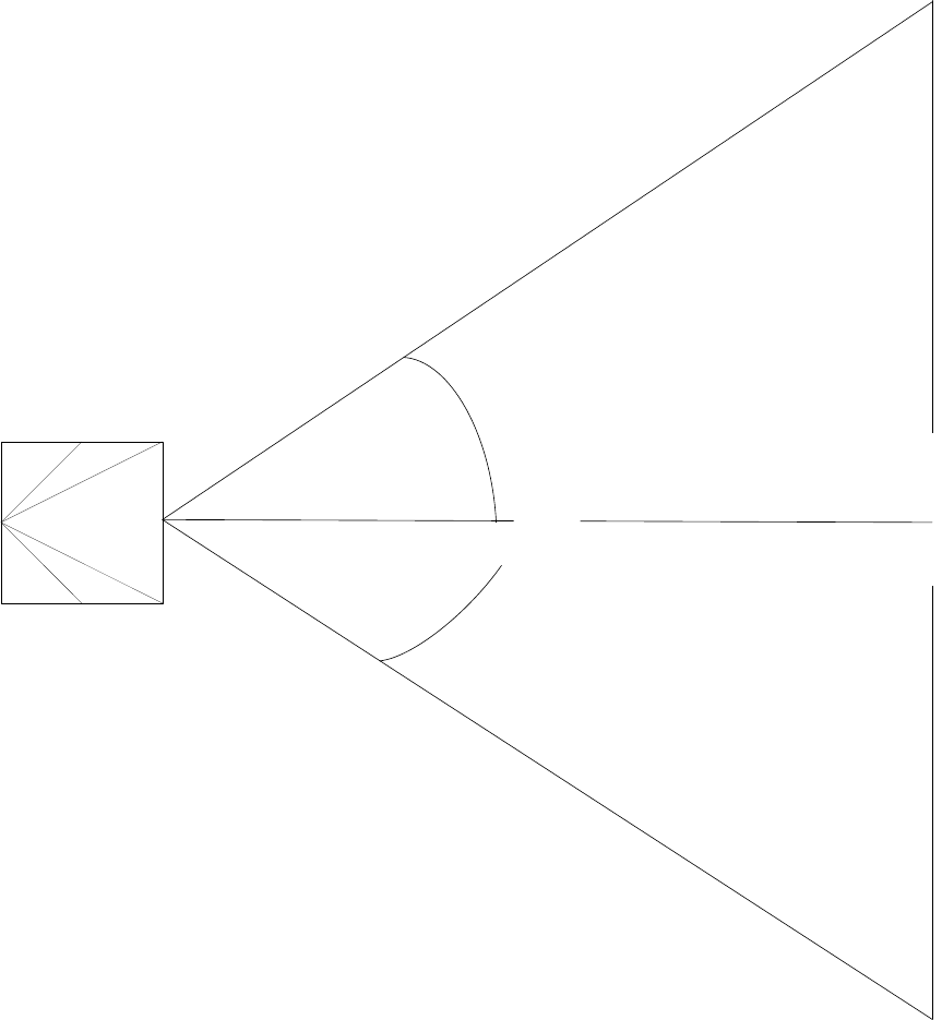
You can visualize the radio coverage area of the Digital Range Extender as a cone with a 75 degree dispersion
whose starting point is the antenna. Attached is a two dimensional drawing of the antenna radio coverage,
where the area inside the triangle has radio coverage.
C
MTX
Antenna 75°
Width = Target Area
Distance
Radio Coverage Area
The first step in achieving adequate radio coverage is determining the area where the customer requires increased
operations. Once the area has been identified, the distance of the antenna from the target coverage area is calculated as
follows:
Target Area = Distance * 1.5
Example:
Final Draft
3M Building and Commercial Services Division
Communications Business
St Paul, MN 55144 ©3M 2008. All Rights Reserved
90-0024-0085-2
If an area 15 ft wide needs radio coverage, the antenna needs to be at a distance of 10 ft or greater in
order to have adequate radio coverage.
EQUIPMENT NEEDED
• Wire (18 Gauge recommended) to connect lighting arrestor to Earth Ground
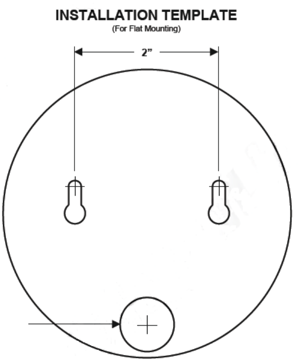
• Mounting Hardware for antenna
BILL OF MATERIALS
• 78-8117-4330-7 – Pigtail - SMA Male to N Female Adaptor Cable (90deg.)
• 78-8117-4331-5 – Lightning Arrestor (N Male to N Female)
• 78-8117-4332-3 – 2.4 GHz 8 dB Round Patch Antenna (Female)
• 78-8117-4333-1 – Coax Cable (100 ft) w/ N Male Connectors
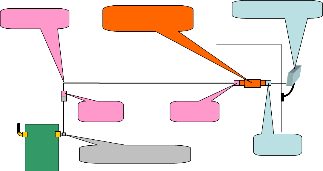
INSTALLATION WITH A DIGITAL WIRELESS BASE STATION
1. Remove the Base Station cover
2. Disconnect power to the Base Station
3. Remove either the left or right base station antenna
4. Connect the pigtail to base station antenna connector, in spot where antenna was removed
2.4 GHz, 8dBi Round Patch
Antenna (Female)
BaseStation
Pigtail SMA Male To N Female
Ada
p
ter Cable
N Male
Connector
N Female
Connector
Coax Cable
(100 ft)
N Male
Connector
Lightning Arresto
r
(N Male To N Female)
MUST BE EARTHED!!!!!!!!!
Final Draft
3M Building and Commercial Services Division
Communications Business
St Paul, MN 55144 ©3M 2008. All Rights Reserved
90-0024-0085-2
NOTE: DO NOT use a tool to tighten the pigtail to the Base Station, leave the connection finger tight.
5. Connect coaxial cable to pigtail.
NOTE: Be sure to form coaxial cable into a "drip loop" and secure to mounting surface when connecting to
Remote Antenna
6. Reconnect power to the Base Station
7. Attach the Base Station Cover.
8. Locate the area in which enhanced radio coverage is desired
NOTE: Obstruction-free line of sight to headsets is required with no large solid metal objects between Remote
Antenna and headset.
9. Pull the Coax Cable to desired antenna location.
10. Connect the lightning arrestor to Coax
11. Connect the lightning arrestor to antenna
12. Test the system range.
• Have someone hold the antenna in the selected location
• Verify antenna operation in required area
• If necessary reposition or move the antenna in order to get desired coverage
13. Mount Antenna in location in order to get desired coverage
14. Mount the lightning arrestor
15. Run 18 Gauge wire from lightning arrestor to an Earth Ground
16. Test the system range.
Final Draft
3M Building and Commercial Services Division
Communications Business
St Paul, MN 55144 ©3M 2008. All Rights Reserved
90-0024-0085-2
FCC NOTICE: The use of all radio equipment is subject to radio regulations in each country. It is the
responsibility of the purchaser/installer/operator to insure that only approved equipment/systems are
deployed. For the ISM band equipment manufactured, sold/or used in the USA, FCC Title 47, Part 15
governs the sale, lease, use and manufacture of equipment (wireless LAN cards, wireless Access points,
amplifiers, etc.) and prohibits the same unless such equipment is used in the FCC-certified system
configuration with which such equipment is authorized.
According to FCC rules, this equipment requires professional installation. This equipment must be
purchased only from 3M authorized dealers. Installation must be controlled and done by 3M certified
professionals. The installation of this equipment requires special training to ensure that placement and set
up is done appropriately to meet the needs of individual customers and locations. Installation of this
equipment also may require a trained electrician to ensure system components are installed in compliance
with applicable building codes. This equipment is intended for use in industrial or commercial
environments only, and is not intended for use by the general public.