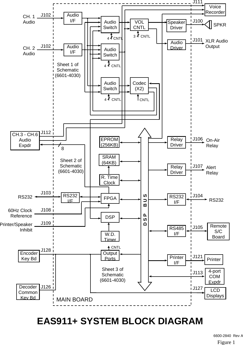
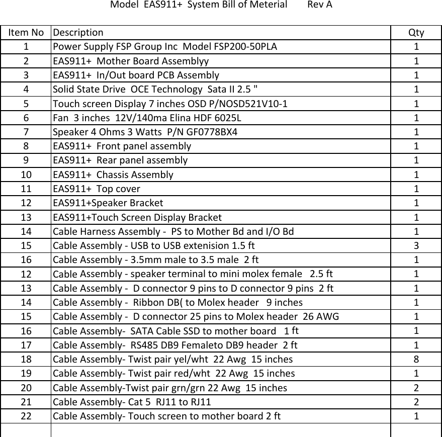
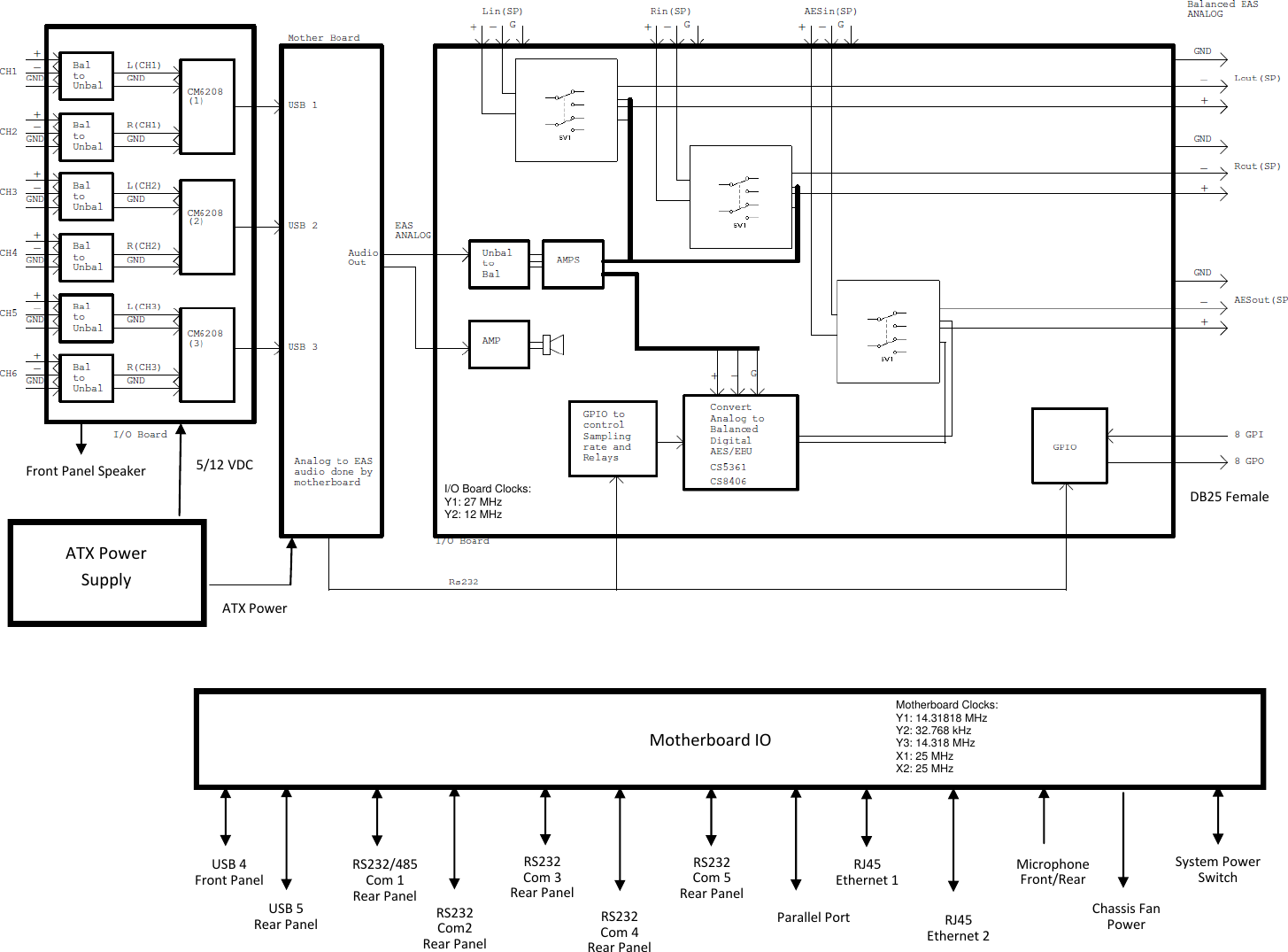
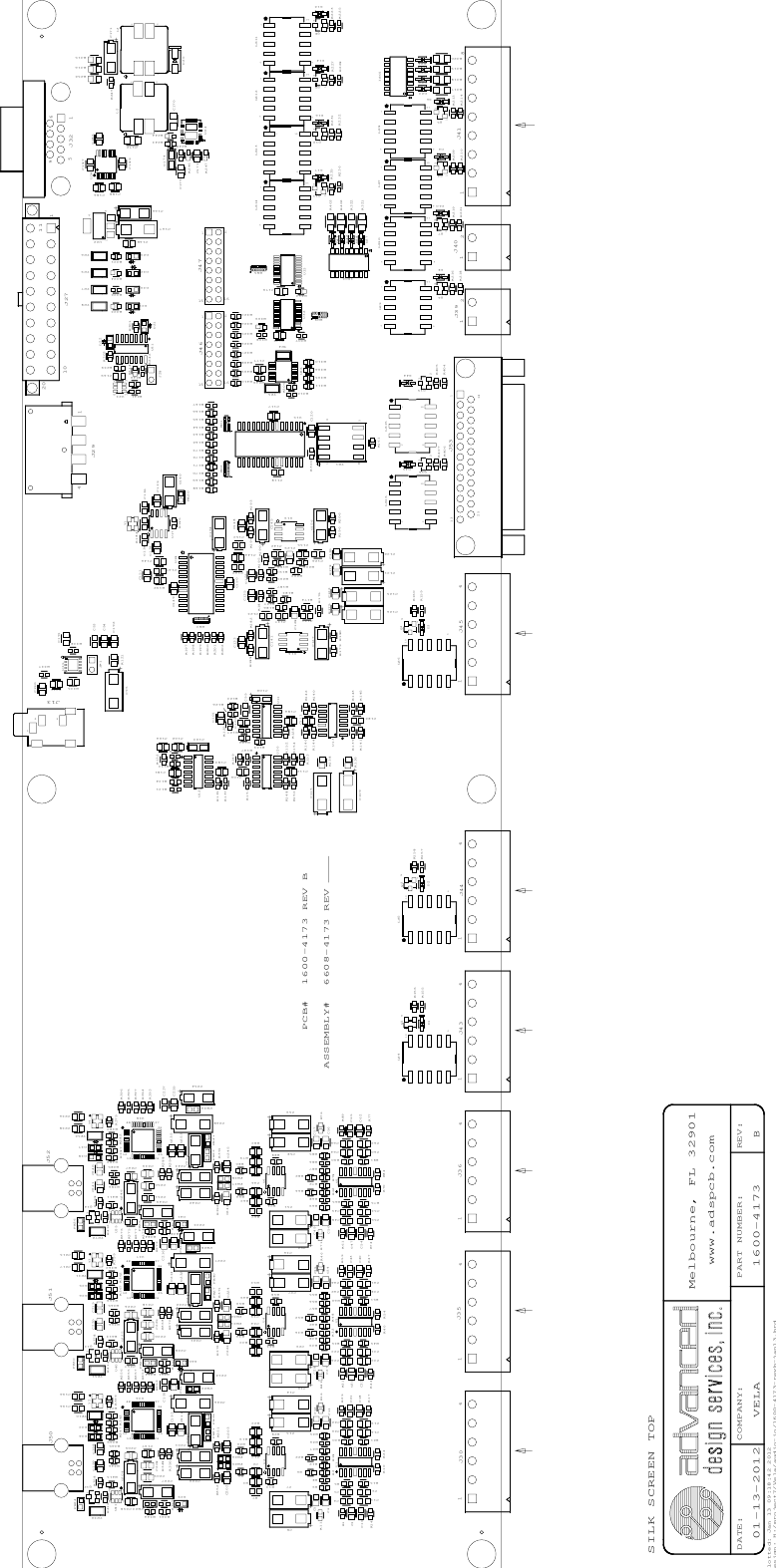
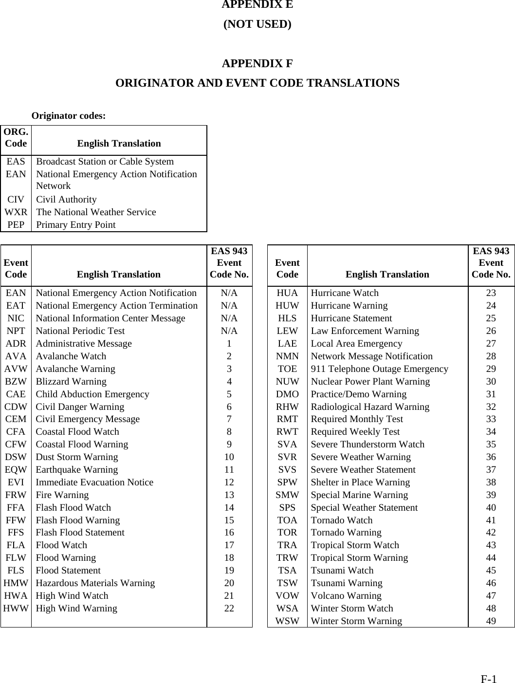
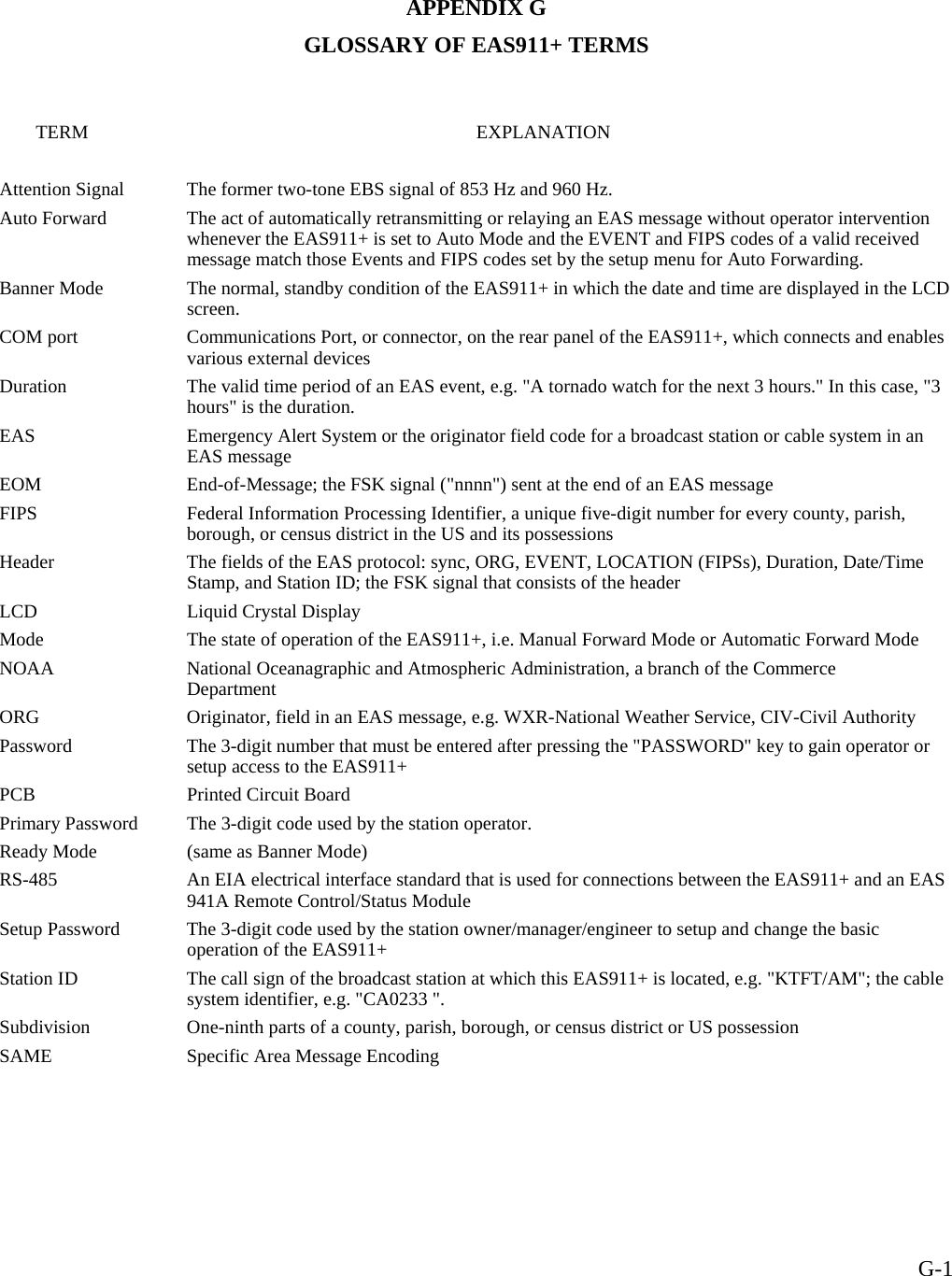
TFT EAS911PLUS EAS Encoder/Decoder User Manual

TFT Inc EAS Encoder/Decoder

User manual

 P/N 5004-EAS911+ REV. B  January 2013 EQUIPMENT SERIAL NO.    SHIPMENT DATE            MODEL EAS911+ EAS-CAP USER’S GUIDE                    TFT, INC. 1953 Concourse Drive San Jose, CA 95131-1708 TEL: (408) 943-9323 FAX: (408)432-9218 EMAIL: techsupport@TFTInc.com
  iCONTENTS  SECTION I - GENERAL INFORMATION Paragraph Title Page 1.1 EQUIPMENT DESCRIPTION  .............................................................................................................................. 1-1 1.2   SPECIFICATIONS. ................................................................................................................................................ 1-1 1.3     FCC COMPLIANCE STATEMENTS………………………………………………………………………….... 1-4 1.4   WARRANTY INFORMATION  ............................................................................................................................ 1-4 1.5   CLAIMS FOR DAMAGE IN SHIPMENT  ............................................................................................................ 1-4 1.6  TECHNICAL SUPPORT  ....................................................................................................................................... 1-4  SECTION II – PRE-INSTALLATION CHECKOUT 2.1   UNPACKING AND INSPECTION  ....................................................................................................................... 2-1 2.2   FRONT PANEL INDICATORS  ............................................................................................................................ 2-1 2.3   REAR PANEL CONNECTORS  ............................................................................................................................ 2-2 2.4   INTERNAL JUMPERS  .......................................................................................................................................... 2-3                        SECTION III - INSTALLATION Paragraph Title Page 3.1   INTRODUCTION  .................................................................................................................................................. 3-1 3.2  MOUNTING AND CONNECTION (ANALOG INSERT)  .................................................................................. 3-1 3.3   MOUNTING AND CONNECTION (DIGITAL INSERT)  ................................................................................. 3-21  SECTION IV – THEORY OF OPERATION 4.1   INTRODUCTION  .................................................................................................................................................. 4-1 4.2   SYSTEM BLOCK DIAGRAM  .............................................................................................................................. 4-1 4.3   DETECTION FRAMING CONTROL AND DETECTION VERIFICATION ...................................................... 4-1 4.4  DELAY AND SWITCH.......................................................................................................................................... 4-2 4.5 DETECTION AND CONTROL ............................................................................................................................. 4-3 4.6 POWER SUPPLY ................................................................................................................................................... 4-3   SECTION V – INSTALLATION 5.1     INTRODUCTION………………………………………………………………………………………………  5-1 5.2     ENCODER AUDIO OUTPUT LEVEL ADJUSTMENT……………………………………………………   5-1
  iiCONTENTS (Continued)  5.3     DECODER AUDIO INPUT LEVEL ADJUSTMENT………………………...………………………… 5-2    5,5     DIGITAL INTERFACE (RS232)……………………………………………………………………….… 5-2  5.6     DIGITAL INTERFACE (RS232)…………………………………………………………………………..5-2 5.7     DIGITAL INTERFACE (RS485)…………………………………………………………………………. 5-3 5.8     THE ON-AIR RELAY …………………………………………………………………………………….. 5-3 5.9     THE ALERT RELAY ………………………………………………………………………………………5-3 5.11    SPEAKER INHIBIT ……………………………………………………………………………………...  5-3 5.15    MOVING MESSAGE SIGNS ……………………………………………………………………………. 5-3  SECTION VI – OPERATION 6.1     INTRODUCTION …………………………………………………………………………………………  6-1 6.2     NETWORK CONNECTION  …………………………………………………………………………….. 6-1 6.3     OPERATING MODE DETAILS………………………………………………………………………….. 6-2 6.4     CAP SET UP MODE PROGRAMMING …………………………………………………………….....   6-3  SECTION VII – THEORY OP OPERATION 7.1     GENERAL DESCRIPTION AND PURPOSE …………………………………………………………..  7-1 SECTION VIII – MAINTENANCE AND REPAIRS 8.1    INTRODUCTION…………………………………………………………………………………………..  8-1 8.2    TOOL AND TEST EQUIPMENT REQUIREMENTS …………………………………………………   8-1 8.3    ROUTINE MAINTENANCE …………………………………………………………………….……….  8-1 8.5    DIAGNOSTICS AND REPAIRS …………………………………………………………………………  8-2 8.7    TROUBLE SHOOTING …………………………………………………………………………………    8-2 8.8     TFT SERVICE DEPARTMENT ……………………………………………………………………….     8-3  APPENDICES  APPENDIX A - ENGINEERING DRAWINGS APPENDIX B - PARTS LISTS APPENDIX C - FIPS CODE PART A  APPENDIX C - FIPS CODE PART B APPENDIX D - 911+ Menu Listing APPENDIX E_F_ ORIGINATOR and EVENT CODES TRANSLATIONS  APPENDIX G - GLOSSORY
 1-1SECTION I  GENERAL INFORMATION 1.1   INTRODUCTION This EAS911+ User’s Guide is arranged in seven sections, as follows: Section I: General Information A general description of the EAS911+, its purpose, its specifications, general information on the FCC designator, FCC compliance statement, warranty and damage claim procedures, and technical support information.  Section II Getting To Know Your EAS911+ and Related Equipment Overview of the various system components of the EAS911+ and related equipment. Control and Indicator functions, basic component functions,  and their interconnection. Section III: Pre-Installation Checkout Some basic test methodology on the EAS911+ and its related equipment. The user should find it useful to perform the tests in this section with all the EAS911+ equipment on a lab bench. Section IV: Programming The EAS911+ Detailed description of setup procedures of various EAS911+ system parameters, e.g. system date and time, station ORG and FIPS codes, Auto Forward events and locations selection, as well as enabling of optional features. Section V: Installation Instruction for  installing and adjusting various system components of the EAS911+. Section VII: Operation      Basic description of I/O control circuits. Section VIII: Maintenance and Repair     Describes routine maintenance procedures and tools and equipment requirements. 1.2 EQUIPMENT DESCRIPTION The EAS911+ is a combined Emergency Alert System (EAS) Encoder and Decoder and CAP (Common Alerting Protocol) receiver that enables broadcasters, cablecasters, and emergency managers to receive, store, forward, and originate Emergency Alert Messages as required by the FCC’s EAS Rules.  By using the EAS digital and CAP protocols prescribed by the FCC, the EAS911+ can function as a sentinel to alert operators to the receipt of emergency messages.  Forwarding of only certain messages with a minimum of operator intervention can be achieved selectively, simply, and automatically. The Encoder section of the EAS911+ is easily programmed to originate emergency alerts in the proper EAS protocol for specific geographic areas as small as one-ninth of an ordinary county.  Although the EAS911+ Decoder stores all received messages, it only forwards and interrupts programming for those messages that meet users’ specific instructions.  These instructions, protected by two levels of security, relieve the operator of needing to make crucial decisions at critical times.  Operators are guided by the EAS911+ Encoder section front panel layout to program event codes and locations.  Emergency messages can then travel quickly and efficiently through the Emergency Alert System. Note: EAS messages with the Event code “EAN” cannot be generated by the normal EAS911+. If origination of an EAN message is needed, contact the factory beforehand. The EAS911+ has two operating modes: automatic and manual.  In automatic mode, only those messages which meet specific criteria are forwarded to the transmitter.  With the exception of the required national level events, only messages “tagged” by management are allowed to interrupt programming.  For minimal or unattended operation, the EAS911+ can perform all the critical emergency alert functions in automatic mode with the optional voice recorder option without operator assistance.  For manual mode, no messages are forwarded, except for required national level messages, unless sent by an operator.  All incoming messages are recorded, and their header information is stored and available for review or subsequent manual forwarding. The digital voice message recording makes an incoming audio message, of up to two minutes, always available for the operator’s immediate review.  The operator can then decide whether to forward the last message received after review of the complete header and voice message.  With the EAS911+ voice recorder it is not necessary for the
 1-2operator to transcribe or remember text.  A touch screen display gives the operator instant access to the last ten messages either received or sent. Six audio inputs and two RS-232 data inputs are standard on the EAS911+ to connect to receivers for the two required monitoring assignments of the EAS911+.  An Internet/Ethernet connection is provided for connection to CAP servers. A single audio output connects to external audio switching and distribution systems or to an optional TFT EAS 940A transmitter/program interrupt unit.  This optional interrupt unit provides four balanced, isolated  input and output channels that are switched to a combined common signal during an emergency message transmission.  The common audio output provided by the EAS911+ contains all the Header, Attention Signal and EOM codes in proper EAS format for emergency alerting.   1.3   SPECIFICATIONS The EAS911+ performance and physical specifications are listed in Table 1.3-1.  Table 1.3-1.  EAS911+ Specifications   ENCODER SECTION Protocol ............................. FCC EAS codes, 520.83 bits per second.  2083.3 Hz mark and 1562.5 Hz space   frequency,  ASCII  8-bit characters Attention Signal ................. 853 and 960 Hz ±5 Hz. Default for 8 seconds, the FCC fixed duration. PASSWORD  Key ............. Enables 3-digit password entry for operator level .  Additional 3-digit password required for program changes EXIT Key ........................... Interrupts operation in progress and returns system to Banner/Ready mode PRACTICE  Key ................ Allows closed-loop self-test for training and unit performance verification; inhibits on-air relay closure and transmission of data to COM ports SEND HEADER  Key ........ Activates transmit relay and sends pre-constructed  header message SEND EOM Key ................ Activates transmit relay and sends End Of  Message code EVENT Keys ..................... 12 keys for user-assigned events WEEKLY TEST Key .......... Allows the EAS routine weekly test to be generated with a minimum of keystrokes LOCATION(S) Keys .......... 14-keys for user-assigned locations SUBDIVISION Keys .......... Allows selection of 9 subdivisions within a location  DURATION Keys .............. User-entered duration of the event in prescribed interval CONFIRM Keys ................ Confirms completion of each step in encoder programming  ON-AIR RELAY LED ......... Indicates that the On-Air relay is closed DECODER SECTION REVIEW  Key .................... Allows review of last valid received message  LED Indicators ................... 5  yellow  LEDs to indicate incoming EAS channel, four analog and one digital.  Two yellow LEDs to indicate AUTO or MANUAL forwarding mode of operation and one red LED to show ALERT relay status
 1-3OPERATION KEYS SPEAKER Key  ........................ Turns speaker ON and OFF;  monitors inputs PRINT Key  .............................. Commands the printer to print the item shown on the LCD Screen ENTER, EXIT, UP  ................... Assist initial setup and programming of the equipment  and DOWN Keys REAR PANEL Audio Inputs  ............................ Six audio channels for FCC EAS or NOAA SAME protocol.    Balanced  or  unbalanced,       10 k-Ohms, approx. 0.5 Vp-p to 2 Vp-p.  Internet/Ethernet Inputs.............Two RJ-45 jacks Data Channels  ........................ RS-232, 1200 baud ASCII, two for input and output Audio Output  ........................... -10 to +10 dBm, 600-ohm balanced, XLR connector On-Air Relay  ............................ Relay contact closure, energized when a selected message is decoded for automatic forwarding or when the Encoder is activated Message Alert Relay  ............... Relay contact closure, energized when an EAS or CAP message is decoded RS-485  .................................... Twisted pair wiring connection for optional remote control/status module Speaker Inhibit  ........................ Connects to external switch or relay contacts.  Normal operation on contact open.  Speaker operation inhibited (muted) on contact closure COM1, COM2, COM3  ............. Optional features when the COM Port Expander is installed and COM4 MECHANICAL AND ENVIRONMENTAL Input Power  ............................. 117 VAC ±10%,  60Hz, 40 watts maximum. Operating Temperature  ........... 0 °C to 50 °C Size  ......................................... 3.5" x 19" x 16" Net Weight ............................... Approximately 12 lbs. Shipping Weight  ...................... Approximately 14 lbs.
 1-41.4             Part 11 and Part 15 Compliance Statement FCC Information: FCC ID: BIOEAS911PLUS The TFT EAS911+ is fully compliant with FCC Part 11. This device complies with part 15 of the FCC Rules. Operation is subject to the following two conditions: (1) This device may not cause harmful interference, and (2) this device must accept any interference received, including interference that may cause undesired operation. NOTE: This equipment has been tested and found to comply with the limits for a Class A digital device, pursuant to part 15 of the FCC Rules. These limits are designed to provide reasonable protection against harmful interference when the equipment is operated in a commercial environment. This equipment generates, uses, and can radiate radio frequency energy and, if not installed and used in accordance with the instruction manual, may cause harmful interference to radio communications. Operation of this equipment in a residential area is likely to cause harmful interference in which case the user will be required to correct the interference at his own expense.  1.5  WARRANTY INFORMATION The following warranty policy and limitations are applicable to the Model EAS911+ . TFT, Inc. warrants each manufactured Model EAS911+ to meet published specifications and to be free from defects in material and workmanship. TFT will repair or replace, at its expense, for a period of one (1) year from the date of shipment of equipment, all parts which are defective from faulty material or workmanship. This Warranty does not cover equipment which has been misused and/or altered by the user. Units found to be defective during the warranty period shall be returned to TFT with transportation charges prepaid by the BUYER. It is expressly agreed that replacement and repair shall be the sole remedy of the SELLER with respect to any non-conforming equipment and parts thereof, and shall be in lieu of any other remedy available by applicable law. All returns to the factory must be authorized in advance by TFT. Upon examination by the factory, if any EAS911+ Equipment is found to be defective, the unit will be repaired and returned to the BUYER with transportation charges prepaid by TFT during the warranty period. Transportation charges for the Encoder and Decoder units found to be defective within the first 30 days of the warranty period will be paid both ways by TFT . Transportation charges for warranty returns wherein failure is found not to be the fault of TFT or one year after the delivery of the equipment shall be paid both ways by the BUYER. This warranty does not apply to equipment which, in the opinion of the SELLER, has been altered or misused. NO OTHER WARRANTY IS EXPRESSED OR IMPLIED. TFT IS NOT LIABLE FOR ANY CONSEQUENTIAL DAMAGES. 1.6          CLAIMS FOR DAMAGE IN SHIPMENT Your instrument should be inspected and tested by the method given in Section II of this manual as soon as it is received. If the instrument is damaged in any way or fails to operate properly due to transportation damage, file a claim with the carrier or, if insured separately, with the insurance company. 1.7   TECHNICAL SUPPORT OUR CUSTOMER SERVICE FOR EAS PRODUCTS IS AVAILABLE FROM 8:00AM TO 5:00PM PACIFIC TIME MONDAY THROUGH FRIDAY. PLEASE CONTACT US IF YOU NEED ASSISTANCE  TFT, Inc. 1953 Concourse Drive San Jose, CA 95131-1731   Tel: (408) 943-9323   Fax: (408) 943-9218 Email: techsupport@TFTInc.com
 2-1SECTION II GETTING TO KNOW YOUR EAS911+ AND RELATED EQUIPMENT 2.1   INTRODUCTION This section provides an overview description of the EAS911+ equipment including Front Panel controls and indicators, Rear Panel connectors,  options and other related peripheral equipment. 2.2   UNPACKING & INSPECTION Upon receiving the equipment, inspect its shipping container and contents for shipping damage. Keep all packing material until equipment performance is confirmed. If any of the equipment is damaged or fails to operate properly due to transportation damage, file a claim with the transportation company or, if insured separately, with the insurance company. The following items should come with the equipment. Please notify TFT if any items are missing. Description Part No Qty Installation and Operation Guide  5004-EAS911+  1 Power Cord  1950-7742  1 Warranty Notice  3002-0002  1 Warranty Card  3001-0420  1 2-PIN Female Terminal Block Connector  1700-1203  2 6-PIN Female Terminal Block Connector  1700-5007  6 8-PIN Female Terminal Block Connector    1    2.3   THE FRONT PANEL The EAS911+ Front Panel is a collection of input switches and touch screen display microphone input and USB port .   Functionally they are as illustrated in Figure 2.3.1 and and described in paragraphs 2.3.1. 2.3.1   Front Panel     Figure  2.3-1. 911+ EAS-CAP Front Panel
 2-2Table 2.3-1. Front Panel  ITEM TITLE  FUNCTION     1  Touch screen display  Color, interactive display and control surface to provide information about operation and programming. Different pages offer EAS and CAP message information and control of aspects of the EAS911+   2  Microphone input   3.5mm jack. To provide an microphone audio input to record an emergency audio message for EAS message origination, substitution of an audio message from a received message, or to record the pre-message audio announcement required for cable system.    3  USB Port  USB 2.0 To provide connection to various USB devices, typically an external printer or storage device.         2.4   THE REAR PANEL The EAS911+ Rear Panel has Input/Output connectors for EAS related or optional equipment. Figure 2.4 shows the Rear Panel Configuration.    Figure 2.4.1  Rear Panel   Table 2.4 Rear Panel Connectors ITEM TITLE  FUNCTION 1  CH 1, 2, 3, 4, 5, 6 AUDIO INPUT  Provides six balanced inputs for audio from EAS sources. 2  Program Audio IN/OUT  LEFT  High level analog loop through
 2-33  Program Audio IN/OUT  Right   High level analog loop through 4  AES Audio  6-pin connector for AES/EBU digital audio loop through  5  Alert Relay    2-pin connector.  2-wire relay contact.  Relay is normally open.  Relay contacts close when a valid EAS message header is decoded.       6  ON-AIR RELAY  2-wire relay contact.  Relay is normally open.  Relay contacts close when an EAS message is transmitted. 7  GPOUT and GPIN     6-pin connector for control and status of external devices and switches 8 GPIO Connector  THIS THIS THIS THIS 25-pin D-connector for control and status of external devices and switches 9  Accessory Port  25-pin D-connector for connection to TFT accessory devices, such as SDI/HDI video interrupt units      10  RS485,  COM1 Port  9-pin D-connector.   Bi-directional balanced RS-485 port for an optional TFT EAS 941A Remote Control/Status Module interface. Also serves as a tally input when external EAS 941A Remote Control/Status Modules are not used.  See 4.26.1 for operation as a tally input 11  Character Generator,  RS232  9-pin D-connector.   Used for digital decoder input and output (RS-232, 1200 baud).  Decodes, processes and forwards messages in standard ABAB...ZCZC...LLLL EAS protocol.  Also used for RS-232, 1200 baud ASCII output of all decoded EAS headers in EAS ABAB...ZCZC... protocol.  The protocol is preceded by an ASCII text translation of the header.  The translation is prefixed with PRESELECT: or NONPRESELECT:  to indicate whether the message passed the forwarding filter. 12  Sign, RS232  9-pin D-connector.   Used for digital encoder output (RS-232, 1200 baud) of EAS protocol ASCII headers.  Outputs all received and transmitted headers in standard ABAB...ZCZC...LLLL EAS protocol, as well as the three EOMs (ABAB...NNNN). 13  COM 5  Software defined RS-232 port 14  COM 6  Software defined RS-232 port 15  RS-232  9-pin D-connector.    16  USB   USB 2 for connection to external devices such as printer or storage devices 17  Ethernet 0  For Internet/Ethernet connection to CAP server 18  Ethernet 1  Not presently supported (future availability) 19 AC Power Switch   12  AC Power Input Socket  Recessed IEC connector for a standard U.S. 120 VAC, 60 Hz line cord.      2.5          OPTION 2.6   RELATED EQUIPMENT The EAS911+ can accommodate various external equipment to comprise a complete Emergency Alert System. Some of this equipment is described in the following paragraphs. 2.6.1   TFT EAS 930A Multi-Module Receiver The TFT Model 930A Receiver System is a separate, 1-3/4" rack-mount chassis. It can accommodate six different plug-in receiver types for four available slots:
 2-4•   AM  •   VHF LOW Public Safety •  FM  •   VHF HIGH Public Safety •  NOAA Weather Radio  •   UHF Public Safety These receivers can be used as sources for the EAS911+ audio inputs. This allows a user to plug up to four different receivers, each with automatic switchover capability, into the chassis, then connect them to the EAS911+. There is one output per receiver. A separate data sheet is available for the TFT EAS 930A receiver. 2.6.2   TFT EAS 940A Program/Transmitter Interrupt Unit The TFT Model EAS 940A Program transmitter Interrupt unit interrupts a station's audio program to insert an EAS Header and voice message. Normal program audio is resumed at the conclusion of the message. The EAS 940A has four program inputs, an EAS audio input and four program outputs.  During an EAS alert, the EAS audio  is routed to all four program outputs. It uses internal audio relays, and it connects to ON-AIR relay contacts J106 and audio output J101 on the EAS911+ rear panel. The EAS 940A can be located up to 2,000 feet from the EAS911+. 2.6.3   TFT EAS 941A Remote Control/Status Module The EAS 941A Remote Control/Status Module allows limited operation of the EAS911+ from a remote location. It duplicates certain major functions of the EAS911+ front panel. Interfacing via RS485 single twisted pair wiring to the EAS911+,  the EAS 941A may be located at distances up to 2000 feet. 2.6.4   TFT EAS 943 Telephone Access Unit The EAS 943 Telephone Access Unit allows public officials, emergency management officials, and authorized personnel to generate, review, and forward EAS messages using a Touch-Tone telephone. It provides the capability of making direct “over the air” voice patch or recording and playback of voice messages using the EAS911+’s internal digital voice recorder. The EAS 943 translates DTMF codes into data commands that are interpreted by the EAS911+ EAS-CAP. 2.7 PRE-INSTALLATION INFORMATION Before installing your TFT EAS911+, you should be familiar with the requirements of Part 11 of the FCC rules, as amended. 2.7.1   Obtaining A Copy of the Operational Area/State Plan The TFT EAS911+ is very flexible and can be adapted to your Operational Area/State Plan. To obtain a copy of the plan, contact your State’s Emergency Coordinator or the broadcast representative for your operational area. Names of State and local contacts are available from the FCC website, www.fcc.gov. 2.7.2   Obtaining Monitoring Assignments The EAS Rules require monitoring two stations in your area and the FEMA IPAWS-OPEN CAP server at https://apps.fema.gov or other approved CAP server detailed in your State’s operational Area/State Plan. These stations are listed in the operational Area/State Plan and in the FCC Mapbook, which is also available from the FCC EAS office in Washington, D.C. In most, but not all cases, the FCC assigned stations will be AM or FM broadcast stations. 2.7.3   Optional/Additional Monitoring In addition to the FCC assigned stations it may be desirable to monitor other sources and originators of emergency information who may transmit EAS protocol messages or CAP messages, such as NOAA Weather Radio and local government authorities. 2.8   PROGRAMMING WORKSHEET FORM Completing the information on the following work sheet before programming the EAS911+ will greatly reduce the time required to program the Encoder/Decoder. The worksheet will also provide a convenient record should future re-programming be required.
 2-5 PROGRAMMING WORKSHEET   FCC Monitoring Assignment, CH 1               (Station)  (Frequency)   FCC Monitoring Assignment, CH 2               (Station)  (Frequency)   FCC Monitoring Assignment, CH 3               (Station)  (Frequency)   FCC Monitoring Assignment, CH 4               (Station)  (Frequency)   FCC Monitoring Assignment, CH 5               (Station)  (Frequency)   FCC Monitoring Assignment, CH 6               (Station)  (Frequency)  CAP Server  https://apps.fema.gov   or ________________   Setup Menu Menu # Description  Programmed Settings 3 DAYLIGHT SAVING?  DST: ENABLE DST: DISABLE  ___  ___ 2  SET STATION TIME ZONE  UTC ±   ____ Hours 1 SET CURRENT DATE/TIME  MON DAY YR HR:MIN    4  SET STATION ORG CODE  EAS CIV WXR  ____  ____  ____ 5  SET STATION FIPS CODE  0SSCCC (see Appendix C) SS=State & CCC=County 0__ __ __ __ __ 6 SET STATION IDENTIFICATION CODE  Station Call Ltrs or other Identifier  "__ __ __ __ __ __ __ __" 7  SET ATTENTION SIGNAL DURATION  0-25 SEC (default= 8sec)   ___ SEC 10  SELECT EVENTS TO AUTO FORWARD  ADR   ___ AVA   ___ AVW   ___ BZW   ___ CAE   ___ CDW ___ CEM   ___ CFA   ___ CFW   ___ DSW   ___ EQW  ___ EVI   ___   FRW   ___ FFA   ___ FFW   ___ FFS   ___ FLA   ___ FLW   ___ FLS   ___ HMW   ___ HWA   ___ HWW  ___ HUA   ___ HUW   ___ HLS   ___ LEW ___ LAE ___ NMN   ___ TOE   ___ NUW  ___ DMO  ___ RHW  ___ RMT   ___ RWT   ___ SVA   ___ SVR   ___ SVS   ___ SPW   ___ SMW   ___ SPS   ___ TOA   ___ TOR   ___ TRA   ___ TRW ___ TSA   ___ TSW   ___ VOW   ___ WSA   ___ WSW  ___
 2-6PROGRAMMING WORKSHEET (Continued) Setup Menu Menu # Description  Programmed Settings 11  ADD LOCATIONS TO AUTO FORWARD (256 Locations Max) __ __ __ __ __ __ __ __ __ __ __ __ __ __ __ __ __ __ __ __ __ __ __ __ __ __ __ __ __ __ __ __ __ __ __ __ __ __ __ __ __ __ __ __ __ __ __ __ __ __ __ __ __ __ __ __ __ __ __ __ __ __ __ __ __ __ __ __ __ __ __ __ __ __ __ __ __ __ __ __ __ __ __ __ __ __ __ __ __ __ __ __ __ __ __ __ __ __ __ __ __ __ __ __ __ __ __ __ __ __ __ __ __ __ __ __ __ __ __ __ __ __ __ __ __ __ __ __ __ __ __ __ __ __ __ __ __ __ __ __ __ __ __ __ __ __ __ __ __ __ __ __ __ __ __ __ __ __ __ __ __ __ __ __ __ __ __ __ __ __ __ __ __ __ __ __ __ __ __ __ __ __ __ __ __ __ __ __ __ __ __ __ __ __ __ __ __ __ __ __ __ __ __ __ __ __ __ __ __ __ __ __ __ __ __ __ __ __ __ __ __ __ __ __ __ __ __ __ __ __ __ __ __ __ __ __ __ __ __ __ __ __ __ __ __ __ __ __ __ __ __ __ __ __ __ __ __ __ __ __ __ __ __ __ __ __ __ __ __ __ __ __ __ __ __ __ __ __ __ __ __ __ __ __ __ __ __ __ 13  ASSIGN, CHANGE OR VERIFY ENCODER EVENT KEYS Note: The card may be easily removed from the holder by using a folded piece of paper to push the card up from the bottom opening slot of the holder.  Three folds approximatly .1 inch wide should be sufficient. WEEKLY TEST _____________ _____________ _____________ _____________ _____________ _____________ _____________ _____________ _____________ _____________ _____________ STATEMENT WATCH WARNING CONFIRM 14  ASSIGN OR RE-ASSIGN ENCODER LOCATION KEYS (31 Locations Max per Key) Note: The card may be easily removed from the holder by using a folded piece of paper to push the card up from the bottom opening slot of the holder.  Three folds approximatly .1 inch wide should be sufficient. 1. __________________________ 2. __________________________ 3. __________________________ 4. __________________________ 5. __________________________ ____________________________ ____________________________ ____________________________ 6. __________________________ 7. __________________________ 8. __________________________ 9. __________________________ 0. __________________________ ____________________________ SUBDIVISION CONFIRM 16 ENABLE INTERNAL VOICE RECORDER  VOICE RECORDER YES (NO)  YES ___   NO  ___ 17  SET REMOTE SIGN PROTOCOL (Requires 4-port COM Expander Module) NO SIGN BETA-BRITE FRIEND SPRING PRO-LITE V.1 PRO-LITE V.2  ____  ____  ____  ____  ____ 18 ENABLE CHAR GEN INTERFACE (Requires 4-port COM Expander Module) CHAR GEN I/F: OFF STD CODI VDS ALT1 ALT2  ____  ____  ____  ____  ____  ____ 19 REMOTE INTERFACE DEFINITION  NO INTERFACE PC/DTMF INTERFACE  ____  ____ PASSWORD    ___  ___  ___ 23 ENABLE REMOTE CONTROL/STATUS MODULE INTERFACE 0 REM/TALLY OFF O REM/TALLY ON 1-16 REMOTE(S)  ____  ____  ____ LOCAL ON AIR REMOTE ON AIR  ____  ____
 2-7PROGRAMMING WORKSHEET (Continued) Setup Menu Menu # Description  Programmed Settings 24 SET ONE-BUTTON WEEKLY TEST OPTION  FAST RWT YES FAST RWT NO  ____  ____ FAST RWT FIPS __ __ __ __ __ __ __ __ __ __ __ __ __ __ __ __ __ __ __ __ __ __ __ __ __ __ __ __ __ __ __ __ __ __ __ __ __ __ __ __ __ __ __ __ __ __ __ __ __ __ __ __ __ __ __ __ __ __ __ __ __ __ __ __ __ __ __ __ __ __ __ __ __ __ __ __ __ __ __ __ __ __ __ __ __ __ __ __ __ __ 25  SET ALERT TIMEOUT (2-15 Minutes) ____  MINUTES 26 SET ONE-BUTTON MANUAL FORWARD  FAST FWD: YES FAST FWD: NO  ____  ____ 27  ENABLE C.G. TEXT FOR RWT (Requires 4-port COM Expander Module) RWT CG: NO RWT CG: YES  ____  ____ 28  SET AUTO MODE TIMER  AUTO MODE: OFF AUTO MODE: ON  ____  ____  AUTO ON: 00:00 AUTO OFF: 00:00  ____:____  ____:____ 31 SET RANDOM REQUIRED WEEKLY TEST  RANDOM RWT: OFF RANDOM RWT: ON  ____  ____  EARLIEST: 00:00 LATEST: 00:00  ____:____  ____:____ 32  SET TRANSMIT DELAY TIME (0-10 Seconds) DELAY  __.__ SECONDS
 3-1SECTION  III PRE-INSTALLATION CHECKOUT 3.1   INTRODUCTION This section describes a functional bench test that should be performed before installing and programming the EAS911+ according to the procedures given in Section IV. By completing the pre-installation checkout, the user can be certain that the equipment is operating properly. 3.2  EAS 911+ QUICK START GUIDE  (For user to become familiar with the display and function of the tabs) 3.2.1 Power Connection Connect the EAS 911+ to a 120 VAC power source.  Note: The unit may take as long as 30 seconds to boot up.   In case of a power failure, the unit will automatically power on after the power is restored.  If it does not, push and hold the Power Switch on the rear of the unit on the rear of the unit above the power plug receptacle and hold it for one second and then release. 3.2.2 Operating Mode Overview   After the unit is plugged in it boots-up in approximately one minute and at that time it will display the default DECODER screen with the DECODER tab highlighted in yellow at the top left of the touch screen. The various tabs at the top of the touch screen turn yellow when touched and access different screens that are briefly explained below:  DECODER tab  Accesses the screen that displays all the decoder operation functions.   ENCODER tab    Accesses the screen for transmitting an EAS message CAP tab  Accesses the screen that displays a real-time log of the last 100 CAP message received whether they match the FIPS Include list or not.
 3-2AUDIO INPUTS tab  Displays a full-scale screen view of the 6 audio input channel levels on bar graphs.  Each channel may be heard on the speaker separately. INFO tab  Gives information about the SYSTEM as a whole, the EAS SERVER, and the CAP SERVER. WARNINGS tab  Displays information messages should the unit not have received or transmitted a weekly or monthly test within eight days. 3.2.3  OPERATING MODE DETAILS  The touch screen has a permanent portion that essentially never changes.  It includes the bottom row and the right edge column of the touch screen. The touch screen is also composed of the various tabs at the top of the screen which bring up various screens.      3.2.4  PERMANENT PORTION OF THE TOUCH SCREEN The permanent portion of the touch screen includes the bottom row and a right edge column.    3.2.4.1  The bottom row includes a yellow window box and the CANCEL key.  The yellow window box normally displays the date and time but can also display other messages about the status of the unit.  The CANCEL key is used to cancel a particular function and return to the default DECODER tab.  3.2.4.2  The right column contains the SPEAKER up and down keys to adjust the speaker volume, the SPEAKER MUTE/ UNMUTED key, SETUP and OPERATION CONFIGURATION keys to gain access the the SETUP and OPERATION mode programming via password protection, and the ON-AIR and ALERT RELAYS status.  3.2.5            TOP PORTION TABS OF THE TOUCH SCREEN 3.2.6 DECODER TAB  This tab accesses the screen that displays all the decoder operation functions.  It includes the following:  MODE key which toggles between the manual forward and the automatic forward modes via password protection.    AUDIO INPUTS with mini- bargraphs to display audio inputs from Audio Inputs channels 1 – 6.  The CAP indicator displays incoming CAP messages, and the RX-D indicator displays input on the COM 5 1200-baud data channel.  MESSAGE WAITING key which flashes for each valid incoming EAS message.  Touch the flashing MESSAGE WAITING key to acknowledge the incoming message and extinguish the key and to proceed with other DECODER functions.  RX LOG window shows the last valid or duplicate alert decoded.    REVIEW RX LOG keys include the NEWEST, NEWER, and the OLDER keys for accessing the last 10 received EAS messages be they valid, duplicate, or expired.
 3-3PRINT key to allow printing of the message displayed in the RX LOG window to an external printer via the front or rear USB port.  VOICE MSG key to permit the previewing of the voice message for the alert shown in the RX LOG.     The EAS 911+ is capable of recording and storing ten distinct voice messages, one for each of the ten alerts in the RX LOG messages.    FORWARD key to permit manual forwarding, with password protection, or one-button forwarding, without password protection, of a valid alert as long as the time duration of the incoming message has not expired.    3.2.2 ENCODER TAB This tab accesses the screen that displays all the encoder operation functions.  It includes the following:  PRACTICE key to allow the user to send a practice RWT or OTHER  alert without engaging the ON-AIR RELAY or activating the character generator interface.  To send a practice alert, touch the PRACTICE key first, followed by touching either the RWT key or the OTHER key.  RWT key to allow the user to send a one-button or (Fast RWT) if this feature has been programmed and enabled.  OTHER key to allow the user to manually encode and send an alert other than RWT.    TX LOG window shows the last alert transmitted.  REVIEW TX LOG keys include the NEWEST, NEWER, and the OLDER keys for accessing the last 10 transmitted EAS messages.   PRINT key to allow printing of the message displayed in the TX LOG window to an external printer via the front or rear USB port.  3.2.3 CAP TAB This tab accesses the screen that displays a real-time log of the last 100 CAP messages received regardless whether they match the FIPS Include list or not. It also includes the following:  CAP LOG window to show the last CAP message decoded.  A lengthy messages may be accessed by using the up and down scroll keys.   REVIEW CAP LOG keys include the NEWEST, NEWER, and the OLDER keys for accessing the last 100 received CAP messages received.  PRINT key to allow printing of a  CAP message displayed in the CAP LOG window to an external printer via the front or rear USB port.
 3-4 VOICE MSG key to permit preview of the voice message for the alert shown in the CAP LOG window.  If the Enable Text-to-Speech On Forwarded Messages function is enabled, a text-to-speech conversion of approximately one minute will take place if the VOICE MSG key is touched to preview a message before sending it; otherwise, the text-to-speech conversion will take place just before the header is transmitted for manual forwarding or at the beginning of an auto forward.  FORWARD key to permit manual forwarding, with password protection, or one-button forwarding, without password protection, of a valid message  so long as the time duration has not expired.  VIEW XML SOURCE key, if touched,  to permit viewing of the current CAP message displayed in the CAP LOG.  3.2.7  AUDIO INPUTS TAB Accesses the screen that displays a full scale screen view of the 6 Audio Input Channel levels on 6 individaul bar graphs.    By touching the respective CH key, a channel’s audio can be heard on the speaker provided the speaker mute key is not set to MUTE and the speaker volume is not set to 0.  3.2.8 WARNINGS TAB  This tab displays informational messages should the unit not have received or transmitted a  test within eight days.  Should a warning message be issued, a flashing WARNING WAITING key will flash next to the lower yellow window box.  Touch this key to acknowledge and extinguish it.  3.3   TEST WITH ANCILLARY EQUIPMENT   3.3.1 Test With EAS 930A Multi-Module Receiver Connect the Audio Output of the EAS 930A Multi-Module Receiver to the EAS911+ Channel 1 Audio Input at CH 1  of the EAS911+ Rear Panel. Press the SPKR key and listen to the EAS 930A broadcast Audio Output through the EAS911+ speaker. At this time it may be convenient to set the audio input levels to the EAS911+. Use an oscilloscope or audio voltmeter to set the input voltages to approximately 1.5 Volt peak-to- peak. 3.3.2 Test with EAS 940A Program/Transmitter Interrupt Unit Refer to the instructions for the EAS 940A Program/Transmitter Interrupt Unit. 3.3.3 Test with EAS 941A Remote Control Status Module Refer to the instructions for the EAS 941A Remote Control/Status Module 3.4  TESTING THE DIGITAL VOICE RECORDER Connect the EAS 930A Multi-Module Receiver or any other audio source to the EAS911+ Channel 1 Audio Input at CH 1  of the EAS911+ Rear Panel. Enter the primary and setup passwords by pressing the Front Panel keys in the followingorder:  Press PASSWORD  The screen will read PASSWORD? And the LOCATION(S) numeric keys will illuminate. Press 9,1,1  The screen will read SELECT EVENT and the EVENT keys will flash. (or Primary Password)
 3-5Press PASSWORD  The TOUCH SCREEN  will read PASSWORD? And the LOCATION(S) numeric keys will illuminate. Press 9,1,2    The TOUCH SCREEN  will read SETUP MENU before changing to read 1. SET CURRENT (or Secondary Password)  DATE/TIME. Press the   Arrow key until the TOUCH SCREEN  Screen displays "21. RECORD VOICE ANNOUNCEMENT". Press ENTER twice to start the Digital Voice Recorder recording. Press EXIT after recording is completed. The Digital Voice Recorder immediately plays back the announcement that was just recorded. Press EXIT to exit. 3.5 TESTING WITH A VIDEO CHARACTER GENERATOR Refer to section 4.21 of this Guide and the Character Generator operation manual. 3.6 TESTING WITH A MOVING MESSAGE SIGN Connect the 2-wire interface cable of the Moving Message Sign to the SIGN RS-232  connector at the Rear Panel of the EAS911+ (refer to section 5.15 of this Guide). Enable the EAS911+ Remote sign option by following the instructions outlined in section 4.20 of this Guide, and ensure the power supply for the sign is turned on. Perform the Required Weekly Test as described in section 3.3, Encoder-to-Decoder Self Test. The EAS message will be displayed on the Moving Message Sign.
 4-1SECTION IV PROGRAMMING THE EAS911+  4.1   INTRODUCTION  The EAS911+ can be programmed to customize its configuration and to automate its operation. EAS911+ programming techniques are described in this section. Programming the EAS911+ is very similar to programming its predecessor, the EAS911. 4.2  EAS MESSAGE OVERVIEW A four-part message is used to activate the Emergency Alert System: 1. Preamble and EAS Header Codes 2. Two-tone audio Attention Signal* 3. Voice or text message* 4. Preamble and EAS End Of Message (EOM) Codes.  * Not used in the required weekly tests. The message is shown pictorially in Figure 4.2-1. Figure 4.2-1 EAS Message Timing Diagram The Preamble and EAS Header Codes are transmitted using Frequency Shift Keying (FSK) at a rate of 520.83 bits per second.  Mark frequency is 2083.3 Hz,  and Space frequency is 1562.5 Hz. Mark and Space times are 1.92 milliseconds. Characters are ASCII 7-bit  as defined in ANSI X3.4-1977. Typical EAS Message Timing Diagram  Notes: (1)  Headers are repeated 3 times. (2)  Not used in weekly tests. Not used for signalling. (3)  Optional (4)  EOM is repeated 3 times. (5)  Event duration is displayed in hhmm format.  i.e. 24 hrs 30 min would be displayed as 2430. (6)  0762049 UTC – (Julian date, Hrs, Min) refers to day 76 @ 2049 hrs. The sys. takes the local time and adds the time-zone offset from menu 2. PREAMBLE SYNC CODE ORIGINATOR ID EVENTCODE LOCATIONCODE EVENTDURATION UTC TIME STAMP STATIONID WHO WHAT WHERE WHEN WHOZCZC- ORG- EEE- PSSCCC+ TTTT- JJJHHMM LLLLLLLL-FSK SIGNAL, APPROXIMATELY ONE SECONDEAS HEADERS TWO-TONE ATTENTION SIGNAL VOICE,  TEXT, or  VIDEO MSG EAS EOM CODE ExampleZCZC- EAS- RWT 006085+ 0015- 0762049- TFT_EAS-(1) (2) (3) (4)Broadcast Station Or Cable System  Transmitted Alert Event Code  FIPS of Locations Affected by Alert  15 Minute Alert Duration  MAR 17, 2003 @ 12:49 PM PST (UTC-8 Hrs) Msg Transmitter/ Re-transmitter ID (5) (6)
 4-2The Attention Signal is transmitted after the EAS header codes and is made up of two simultaneously transmitted tones. The fundamental frequencies of these tones are 853 and 960 Hz. 4.2.1   The EAS Header The EAS header consists of seven segments: 1. Preamble Sync Code 2. Originator ID* 3. Event Code*  4. Location code (including county subdivision code)* 5. Event Duration 6. Time Stamp*   7. Station ID*   * Requires user programming before installation. Details of these codes are described in the FCC Rules and Regulations Part 11, Subpart B, Section 11.31/EAS Protocol and in Appendix C of this guide. The following paragraphs provide a user guide for setting the programmable segments of the EAS Header. 4.2.2  Two-Tone Attention Signal The two-tone attention signal is the same as the old EBS: 853 Hz and 960 Hz tones. It is used only in the required monthly tests and activation of the EAS.  It is not used in the required weekly test (RWT). It is no longer used for signaling. The default duration of the two-tone signal is 8 seconds; however, its duration is user programmable up to 25 seconds.  See Section 4.9 for details. 4.2.3  Getting Started – Setup Menu Programming The display on the EAS911+ contains “soft” keys, color indications, and information to guide you through the setup and operation procedures. Programming the EAS911+ is very similar to programming its predecessor EAS911. It is very important to assemble the information in Section 2, Paragraph 2.8, before you begin. The programming follows the same order as shown in the Programming Summary Sheet. Programming the EAS911+ requires entry of a Primary Password and a Setup Password to allow access to the Setup Menu. The default passwords are 911 and 912, respectively. See Section 4.10 and 4.11 for information on changing the default passwords.  Proceed as follows: 1.  Enter the Primary password by pressing PASSWORD and entering 9, 1, 1,  the  3-digit password, using the 0-9 numeric keys under LOCATION(S). 2. Press PASSWORD and enter 9, 1, 2,  the  3-digit Setup password,  using the 0-9 numeric keys under LOCATION(S). Once the correct passwords have been entered, the LCD Screen will display SETUP MENU briefly then display the first menu item:  1. SET CURRENT DATE/TIME Use the Arrow keys (∆ ∇) to scroll through the Setup Menu items. The Setup Menu items are listed in Table 4.3-1. When a desired menu item is displayed, press ENTER to select it. 4.3   Menu Item 1.  SET CURRENT DATE/TIME NOTE: In order to properly set the Date/Time, program in the following order: A)  Setup Menu 3. DAYLIGHT SAVING? B)  Setup Menu 2. SET STATION TIME ZONE C)  Setup Menu 1. SET CURRENT DATE/TIME This menu sets the current date and local time. Press the ENTER key while 1. SET CURRENT DATE/TIME is displayed on the LCD Screen. The LCD Screen will display the current date and time in 24-hour format. EXAMPLE: JAN 01 95 18:00 JAN will flash, indicating that it may be changed using the Arrow (∆ ∇) keys.
 4-3After finding the correct month with the Arrow keys, press ENTER to accept the displayed month. The Day, Year, Hour and Minute are set in the same manner. Clock seconds are not shown, but are zeroed when ENTER is pressed for selecting the desired minute.
 4-4Table 4.3-1.  Setup Menu Items Menu Item  Refer to Manual Section 1. SET CURRENT DATE/TIME  4.3 2. SET STATION TIME ZONE  4.4 3. DAYLIGHT SAVING?  4.5 4. SET STATION ORG CODE  4.6 5. SET STATION FIPS CODE  4.7 6. SET STATION IDENTIFICATION CODE  4.8 7. SET ATTENTION SIGNAL DURATION  4.9 8. CHANGE PRIMARY PASSWORD  4.10 9. CHANGE SETUP PASSWORD  4.11 10. SELECT EVENTS TO AUTO FORWARD  4.13 11. ADD LOCATIONS TO AUTO FORWARD  4.14 12. VERIFY OR DELETE LOCATIONS TO AUTO FORWARD  4.15 13. ASSIGN, CHANGE OR VERIFY ENCODER EVENT KEYS  4.16 14. ASSIGN OR RE-ASSIGN ENCODER LOCATION KEYS  4.17 15. VERIFY/EDIT ENCODER LOCATION KEY ASSIGNMENT  4.18 16. ENABLE INTERNAL VOICE RECORDER  4.19 17. SET REMOTE SIGN PROTOCOL  4.20 18. ENABLE CHAR GEN INTERFACE  4.21 19. REMOTE INTERFACE DEFINITION  4.22 20. SET LCD CONTRAST  4.23 21. RECORD VOICE ANNOUNCEMENT  4.24 22. VERIFY VOICE ANNOUNCEMENT  4.25 23. ENABLE REMOTE CONTROL/STATUS MODULE INTERFACE  4.26 24. SET ONE-BUTTON WEEKLY TEST OPTION  4.27 25. SET ALERT TIMEOUT  4.28 26. SET ONE-BUTTON MANUAL FORWARD  4.29 27. ENABLE C.G. TEXT FOR RWT  4.30 28. SET AUTO MODE TIMER  4.31 29. RECORD ALERT VOICE MESSAGE  4.32 30. VERIFY ALERT VOICE MESSAGE  4.33 31. SET RANDOM REQUIRED WEEKLY TEST  4.34 32. SET TRANSMIT DELAY TIME  4.35
 4-5 4.4  Menu Item 2. SET STATION TIME ZONE This command permits setting the number of hours that must be added to local Standard Time to reach Universal Coordinated Time (UTC), also known as Greenwich Mean Time (GMT).  Proceed as follows: 1.  Use the Arrow keys to change to menu item 2.  2. Press the ENTER key while 2. SET STATION TIME ZONE is displayed on the LCD Screen. The Arrow keys can be used to adjust the offset from -12 to +12 hours.  3. Press ENTER to accept the correct displayed UTC offset. UTC offsets for the U.S. are listed in Table 4.3-2. Table 4.3-2. UTC Offsets for the U.S. TIME ZONE  UTC OFFSET Eastern Standard Time  - 05 Hours Central Standard Time  - 06 Hours Mountain Standard Time  -07 Hours Pacific Standard Time  -08 Hours Alaskan Standard Time  -09 Hours Hawaiian Standard Time  -10 Hours Note The UTC offset is always calculated with respect to standard time, not daylight saving time. 4.5   Menu Item 3. DAYLIGHT SAVING? Daylight saving time starts at 2 a.m. standard time on the first Sunday in April and ends on the last Sunday in October at 2 a.m. daylight time. The EAS911+ automatically adjusts the local time for daylight saving time if enabled.  Proceed as follows: 1. Press the ENTER key while 3. DAYLIGHT SAVING? is displayed on the LCD Screen.  The LCD Screen will then display DST: ENABLE or DST: DISABLE. 2.  When the desired condition is displayed on the LCD Screen, press ENTER to accept it. EXAMPLE: DST: ENABLE appears on the LCD Screen. If necessary, press Arrow key ∆ or ∇ to toggle to DST: DISABLE. When the desired condition is displayed on the LCD Screen, press ENTER to accept it.   Recommended: Set for daylight saving time ENABLE.
 4-64.6   Menu Item 4. SET STATION ORG CODE The ORIGINATOR code for the station must be selected from Table 4.6-1: Table 4.6-1 Originator Codes ORG CODE  ORIGINATOR CIV Civil Authority EAS  Broadcast Stations or Cable System WXR  National Weather Service PEP  PRIMARY ENTRY POINT Proceed as follows: 1. Press the ENTER key while 4. SET STATION ORG CODE is displayed on the LCD Screen.  The LCD Screen will display the currently selected 3-character ORG code. EXAMPLE: EAS Broadcast Station or Cable System As the Arrow keys are pressed, the LCD Screen will display the ORG codes available, and a description of each. Press ENTER to select a displayed ORG code. 4.7   Menu Item 5. SET STATION FIPS CODE The Federal Information Processing System (FIPS) code (See Appendix C of this Guide) consists of six digits: PSSCCC. P   Defines a subdivision, and must be 0 for station FIPS identification. SS   Is a 2-digit State code. CCC   Is a 3-digit County code. Press the ENTER key while 5. SET STATION FIPS CODE is displayed on the LCD Screen.  The LCD Screen will display the currently selected station FIPS code. EXAMPLE: STATION: 006085 Flashing digits will prompt for entry of the 2-digit state code followed by the 3-digit county code. Use numeric keys 0-9 to enter FIPS code digits. The ∇ key will backspace; the ∆ key will forward space. After the last digit is entered, the selected location will be displayed to prompt the operator to accept it. Press ENTER to accept the displayed FIPS code. Press EXIT to cancel an entry. EXAMPLE:  006085 SANTA CLARA CA The 006085 will be stationary and flashing; SANTA CLARA CA will scroll from right to left. For the Cable Version of the EAS911+: Press the SUBDIVISION key. ZONE: ♦ code appears on the LCD, when code is ALL or 1 to 16. Use the arrow keys (∆ ∇) to scroll through the list of 16 zones. Select a zone for encoding by pressing the ENTER key.  The presence of the  indicates that the zone is selected. Pressing the ENTER key will toggle the diamond  (♦) to change the status of each zone. Press EXIT to confirm and end.
 4-74.8   Menu Item 6. SET STATION IDENTIFICATION CODE This is the call sign of a broadcast station or other identification of a cable station, or NWS office transmitting or forwarding the message. This code is automatically affixed to all outgoing messages by the EAS encoder. It is limited to 8 characters. 1. Press the ENTER key while 6. SET STATION IDENTIFICATION CODE is displayed on the LCD Screen.   The LCD Screen will display the currently selected identification code. EXAMPLE: “WTFT/FM “ is displayed on the LCD Screen. W will begin flashing, indicating that it may be changed using the Arrow keys. After finding the correct alphanumeric character with the Arrow keys, press ENTER to accept. T will begin flashing, indicating that it may now be changed in the same way using the Arrow keys and the  ENTER key to accept. This procedure is repeated until all the characters have been updated. 4.9   Menu Item 7. SET ATTENTION SIGNAL DURATION The attention signal is made up of 853 Hz and 960 Hz tones and is sent after the Headers. The duration of this signal is programmable from 0 to 25 seconds. 1. Press the ENTER key while 7. SET ATTENTION SIGNAL DURATION is displayed on the LCD Screen. The LCD Screen will display the currently selected Attention Signal duration. EXAMPLE: 08 SECONDS is displayed on the LCD Screen with 08 flashing. The Arrow keys increment (∆) and decrement (∇) the duration in 1-second steps. Pressing ENTER accepts the indicated duration. 4.10   Menu Item 8. CHANGE PRIMARY PASSWORD The primary password is used for Encoder access and consists of 3 digits. It is set to 911  at the factory and is configurable from 000 to 999. Press the ENTER key while 8. CHANGE PRIMARY PASSWORD is displayed on the LCD Screen. The LCD Screen will display the current primary password. EXAMPLE: 911 PRIMARY is displayed on the LCD Screen. The first digit, 9, will begin flashing, indicating that it may be changed by pressing one of the numeric entry keys 0-9. After a digit is entered, the next digit will begin flashing. After all three digits have been entered, the entire password will flash, prompting for verification. EXAMPLE: 911 VERIFY will be displayed, with 911 flashing. Press ENTER to accept; press EXIT to leave the password unchanged. 4.11  Menu Item 9. CHANGE SETUP PASSWORD The Setup Password is used for Setup Menu access and consists of 3 digits. It is set to 912 at the factory and is configurable from 000 to 999. Press the ENTER key while 9. CHANGE SETUP PASSWORD is displayed on the LCD Screen. The LCD Screen will display the current Setup password. EXAMPLE: 912 SETUP is displayed on the LCD Screen, with 9 flashing. The Setup password may be changed in the same manner as the Primary password.
 4-84.12 RECOVER LOST PASSWORD If a changed password is lost or forgotten, it cannot be recovered; however, the default Primary and Setup passwords can be restored by entering the following key sequence when in Ready mode. Each of the following key entries will cause PRESS PASSWORD to appear in the LCD.  Do NOT press PASSWORD, but WAIT FOR THE DATE AND TIME TO RETURN before pressing the next key: Press CANCEL, EVENT CONFIRM, 4, 0, 8, 7, 2, 7, 7, 2, 7, 2, LOCATION(S) CONFIRM. (Do This SLOWLY) You will hear a tone acknowledging restoration of the default passwords.  The default Primary password is 911; the default Setup password is 912. 4.13   Menu Item 10. SELECT EVENTS TO AUTO FORWARD EAS events may be selected for auto forwarding. When in Auto Mode, the event code contained in a header will be compared with the event codes selected for automatic forwarding to help decide whether the message should be forwarded. In Auto Mode, priority EAN events will be forwarded automatically without delay.  In Manual Mode, EAN events must be manually forwarded without delay by the operator. Press ENTER while 10. SELECT EVENTS TO AUTO FORWARD is displayed on the LCD Screen. The first EAS event will be displayed. The event will appear in a static display, the description will scroll. EXAMPLE: ♦ ADR Administrative Message The ♦ character indicates that the event has been selected for automatic forwarding. If the diamond is absent, the event has not been selected. The ENTER key selects or deselects an event. The Arrow keys select the next event in alphabetical order. The ENTER key is again used to choose to forward the next displayed event. The process continues until all events have been defined. Press EXIT to end. 4.14   Menu Item 11. ADD LOCATIONS TO AUTO FORWARD  A list of locations to Auto Forward should be specified. When in Auto Mode, the location code contained in a header will be compared with the location codes selected for automatic forwarding to help decide whether the message should be forwarded. A maximum of 256 locations may be forwarded. Press ENTER while 11. ADD LOCATIONS TO AUTO FORWARD is displayed on the LCD Screen. The LCD Screen will display a location of 000000. EXAMPLE: FORWARD: 000000 appears on the LCD Screen. Flashing digits prompt for entry of the 2-digit state and 3-digit county code. Use the numeric 0-9 keys to enter FIPS code digits. the ∇ key will backspace; the ∆ key will forward space. When the last digit is entered, the selected location will be displayed for acceptance. EXAMPLE: 006085 SANTA CLARA CA The FIPS code will flash in a static display; a description of that location will scroll. Press ENTER to add the location displayed; press EXIT to reject it. More locations may be added in the same manner. Duplicate locations are not permitted. The Cable version of the EAS911+ has the capability of addressing additional zones through an RF modulator when used with the TFT cable in-home alerting device.  Zone programming is described in Section 4.15 below.
 4-94.15   Menu Item 12. VERIFY OR DELETE LOCATIONS TO AUTO FORWARD This menu item permits verification or deletion of location codes previously selected for automatic forwarding. Press ENTER while 12. VERIFY OR DELETE LOCATIONS TO AUTO FORWARD is displayed on the LCD Screen. The first of the locations selected for automatic forwarding is displayed on the LCD Screen. The FIPS code is shown in a static display, and a description of that location scrolls. EXAMPLE: ♦ 006085 SANTA CLARA, CA appears on the LCD Screen.  The ♦ indicates that this location has been selected for automatic forwarding. The ENTER key will toggle the diamond off/on, changing the status of each location. The ∆ and ∇ keys can be used to scroll through the list. Press EXIT after deleting locations to forward. Press ENTER to accept changes to the list of locations to forward. If EXIT is pressed, no changes will be made. Duplicate locations are allowed. For the Cable Version of the EAS911+: The cable version of the EAS911+ has the capability of addressing zones of a cable system through an RF modulator.  TFT cable in-home alerting devices can be addressed at one of 16 zones and be selectively alerted by the modulator to Events specific to that zone.  Any zone or combination of zones can be assigned to one of the first 20 FIPS codes to be auto forwarded. In Setup Menu 12. VERIFY OR DELETE LOCATIONS TO AUTO FORWARD, select the desired FIPS code, for example:  ♦ 006085 SANTA CLARA CA appears on the LCD. Press the SUBDIVISION key. ZONE: ♦ code appears on the LCD, when code is ALL or 1 to 16. Use the arrow keys (∆ ∇) to scroll through the list of 16 zones. Select a zone for auto forward by pressing the ENTER key.  The presence of the ♦ indicates that the zone is selected. Pressing the ENTER key will toggle the diamond  (♦) to change the status of each zone   Press EXIT to confirm and end.  4.16   Menu Item 13. ASSIGN, CHANGE OR VERIFY ENCODER EVENT KEYS There are 11 encoder event keys that may be customized by assigning events appropriate to a station's broadcast area. Each key may be assigned either a defined EAS event code or an event code template based on the currently defined EAS event codes. An event code template may be used, along with the STATEMENT,  WATCH, and WARNING keys, to encode an EAS event code when in Encoder Operational Mode. Note that the WEEKLY TEST key is pre-assigned with the EAS event code for the Required Weekly Test event (RWT) and cannot be changed. Access to certain event codes with national significance (for example EAN, EAT, NPT, NIC) is restricted. Press ENTER while 13. ASSIGN, CHANGE OR VERIFY ENCODER EVENT KEYS is displayed on the LCD Screen. The Encoder event LEDs will begin flashing, and the LED screen will display EVENT KEY? When an event key is pressed, the LED for that key will illuminate, and all other event key LEDs will extinguish. The LCD Screen will then prompt by displaying the event currently assigned to that event key. The EAS event code or an event code template will be shown in a static display, and a description of that event code or template will scroll. However, the LCD Screen will display NOT ASSIGNED if a previously unassigned event key is selected.
 4-10EXAMPLES: RMT Required Monthly Test CEM Civil Emergency SVS Severe Weather Statement TO? Tornado Template Actual EAS event codes appear in the static display. The Arrow keys select the next EAS event code or event code template in alphabetical order. Press the ENTER key to select the currently displayed event. Other encoder event keys may then be assigned in an identical manner. After that particular key is assigned, all the event LEDs will begin flashing for the next encoder event key assignment in an identical manner. To verify encoder EVENT key assignments, select an EVENT key as described above, then press EXIT after verifying the event or template assigned to that key. 4.17  Menu Item 14. ASSIGN OR RE-ASSIGN ENCODER LOCATION KEYS Encoder LOCATION keys may be customized by assigning to them locations relevant to a station’s broadcast area. A maximum of 31 locations may be assigned to each LOCATION key. Press ENTER while 14. ASSIGN OR RE-ASSIGN ENCODER LOCATION KEYS is displayed on the LCD Screen. The encoder LOCATION LEDs will begin flashing, and the LCD Screen will display LOCATION KEY? When a LOCATION key is pressed, the LED for that key will be lit, and all other encoder LOCATION key LEDs will be extinguished.  A 000000 FIPS code will be displayed to serve as a starting point for assigning FIPS codes to the selected LOCATION key. EXAMPLE: FIPS 01: 000000 Flashing digits on the LCD will prompt for entry of the 1-digit subdivision code, the 2-digit state code followed by the 3-digit county code. Use the numeric keys 0-9 to enter FIPS code digits. The ∇ key will backspace; the ∆ key will forward space. After the last digit is entered, the selected location will be displayed to prompt the operator to accept it. Press ENTER to accept the displayed FIPS code. 006085 SANTA CLARA The FIPS code will flash in a static display; a description of the location will scroll. Press ENTER to accept the location displayed and add it to the list of locations assigned to the selected LOCATION key. Press EXIT to reject. If accepted, the LCD Screen will be updated. Other FIPS codes may be assigned to the selected LOCATION key in the same manner. Press EXIT to end.  The system will return to the Setup Menu after 31 FIPS codes have been assigned. For cable versions zone programming in Setup Menu 14. ASSIGN OR RE-ASSIGN ENCODER LOCATION KEYS is similar to that in Section 4.15 above.  After all FIPS codes have been assigned to a Location key,  For the Cable Version of the EAS911+: Press the SUBDIVISION key. ZONE: ♦ code appears on the LCD, when code is ALL or 1 to 16. Use the arrow keys (∆ ∇) to scroll through the list of 16 zones. Select a zone for encoding by pressing the ENTER key.  The presence of the ♦ indicates that the zone is selected for encoding. Pressing the ENTER key will toggle the diamond  (♦) to change the status of each zone Press EXIT to confirm and end.
 4-114.18   Menu Item 15. VERIFY/EDIT ENCODER LOCATION KEY ASSIGNMENT Permits a review of the locations previously assigned to the encoder LOCATION keys. Press ENTER while 15. VERIFY/EDIT ENCODER LOCATION KEY ASSIGNMENT is displayed on the LCD Screen. The Encoder LOCATION key LEDs will begin flashing; the LCD Screen will display: LOCATION KEY? When a LOCATION key is pressed, the LED for that key will light, and all other Encoder LOCATION keys will extinguish. If the selected LOCATION key has not yet been assigned, the LCD Screen will display NOT ASSIGNED! briefly, and another LOCATION key may then be selected. If the selected LOCATION key has been assigned, the first location assigned to that key will be displayed on the LCD Screen. The FIPS code will be static and a description of that location will scroll. EXAMPLE: 006085 SANTA CLARA CA Use the Arrow keys to view other locations assigned to the LOCATION key. To verify another LOCATION key, press that key. Press EXIT to return to the Setup Menu. To delete a FIPS code: Select the FIPS code to be deleted with the Arrow (∆ ∇) keys. Press CANCEL. The LCD will display DELETE FIPS? Press ENTER to delete, or: Press EXIT to leave the FIPS unchanged.  4.19   Menu Item 16. ENABLE INTERNAL VOICE RECORDER Verify the presence of the internal voice recorder. Press ENTER while 16. ENABLE INTERNAL VOICE RECORDER is displayed on the LCD Screen. The LCD Screen will display VOICE RECORDER: YES (NO). YES indicates that the voice recorder is installed and enabled. NO indicates that the voice recorder is not installed or it is not enabled. Hardware will detect the presence of the voice recorder and automatically enable it if installed. This function can be used to enable or disable the voice recorder via software. 4.20   Menu Item 17. SET REMOTE SIGN PROTOCOL The COM4 port on the 4-Port Communication Expander Option Module sends serial data to a remote electronic sign through a single twisted-pair interface using RS-232 levels. The protocol must be set for the particular electronic sign being used. Press ENTER while 17. SET REMOTE SIGN PROTOCOL is displayed on the LCD Screen. The LCD Screen displays the name of the electronic sign manufacturer. EXAMPLE: FRIEND SPRING Press the Arrow keys to view other protocols. Press the ENTER key to select the desired protocol when displayed. Press EXIT for no change. 4.21   Menu Item 18. ENABLE CHAR GEN INTERFACE This command enables or disables the character generator interface. The COM2 port on the Four Port Communications Expander Option Module sends serial data to remote character generators using RS-232 levels.  Press ENTER while 18. ENABLE CHAR GEN INTERFACE is displayed on the LCD Screen. The LCD Screen will display STD.  It will then scroll the following: Standard TFT I/F for BSS, Frontline, and D Co. EAS Systems
 4-12The following six submenus are available: CHAR_GEN_I/F:OFF STD Standard TFT I/F for BSS, Frontline, and D Co. EAS Systems CODI  Direct Interface to CHYRON CODI VDS  Direct Interface to VDS 840 ALT1  Alternate TFT I/F for Trilithic EAS Systems ALT2  Alternate TFT I/F for Next Level EAS Systems     Use the Arrow keys to select the desired submenu, then press ENTER to select the displayed setting. If the TFT standard interface is enabled, a character generator must communicate properly in the TFT protocol in order for the EAS911+ to forward EAS alerts automatically.  If the TFT interface is enabled and a character generator is not connected or communicating, all auto-forwarded messages will be aborted.  A message can always be manually forwarded to allow the audio to be transmitted even if the character generator is not connected.  If the CODI interface is enabled, messages will not be aborted if the CODI is not connected. If the CODI interface is selected by pressing ENTER when CHYRON CODI I/F is displayed, you may use the arrow keys and ENTER to select the sub menus listed below.  Again use the arrow keys to select the desired value and press ENTER to store the value.  Press the EXIT key to move one level up in the menu selection process.  The factory set default parameters are shown first in the menu listing below. Note:  Horizontal Phase, Subcarrier Phase and Key Delay should only be adjusted using the alignment procedures described in the Chyron CODI Operator Manual.  SET CHAR HEIGHT  Height = 5 (range is 1-7) SET COLOR  Color:White (also Magenta, Blue, Cyan, Yellow, Green, Red, Black) SET CRAWL SPEED  Speed = 2 (range is 1-6) SET CRAWL COUNT  Crawl Count = 1 (range is 1-8) SET DISPLAY LINE  Line = 50 (range is 30-160) SET HORIZ PHASE  H Phase = 0 (range exceeds ± 90) SET SUBCA PHASE  SubC Phase = 0 (range exceeds ± 90) SET KEY DELAY  Key Delay = 0 (range is ± 10) If the VDS interface is selected by pressing ENTER when VDS I/F is displayed, you may use the arrow keys and ENTER to select the submenus listed below.  Again use the arrow keys to select the desired value and press ENTER to store the value.  Press the EXIT key to move one level up in the menu selection process.  The factory set default parameters are shown first in the menu listing below.  SET CHAR HEIGHT  Height = 3 (range is 1 to 4) SET COLOR  Color:White (also Yellow Cyan, Green, Magenta, Red, Blue or Black) SET CRAWL SPEED  Speed = 2 (range is 1-3) SET CRAWL TIME  Time = 2 MIN (range is 1-9 min)  SET DISPLAY LINE  Line = 40 (range is 40-100) SET VDS EDITOR  OFF   (When ON, the ALERT RELAY will close during EAS transmission to control VDSs second COM port.  The relay will stay closed until the VDS’s timeout. When OFF, all operation is normal.)
 4-134.22  Menu Item 19. REMOTE INTERFACE DEFINITION The COM3 port on the Four-Port Communications Expander Option Module uses full duplex serial data to communicate with a remote telephone interface using RS-232 levels.   Press ENTER while 19. REMOTE INTERFACE DEFINITION is displayed on the LCD Screen. The following two submenus are available:  NO INTERFACE  PC/DTMF INTERFACE   When PC/DTMF interface is enabled, COM3 must be connected to the EAS 943 telephone interface. 4.23   Menu Item 20. SET LCD SCREEN CONTRAST This menu item is used to set the LCD Screen contrast. There are 4 contrast levels (0 to 3), with 0 giving the least,  and 3 giving the most contrast. Press ENTER while 20. SET LCD CONTRAST is displayed on the LCD Screen. The LCD Screen displays the current LCD Screen contrast setting. EXAMPLE: LCD CONTRAST: 2 is displayed on the LCD Screen. Press the Arrow keys to select other contrast settings. The LCD Screen will reflect the new contrast setting. Press ENTER to accept the displayed setting. Press EXIT for no change. 4.24   Menu Item 21. RECORD VOICE ANNOUNCEMENT (for cable systems only) For cable pointer to details channel, an announcement may be prerecorded for later playback. To record the announcement, the Voice Recorder must be installed and enabled. Connect the audio source to the Channel 1 (CH1) audio input of J102 on the EAS911+ rear panel or connect a microphone to the 3.5 mm TRS jack on the front panel. The maximum announcement duration is 25 seconds. Press ENTER while 21. RECORD VOICE ANNOUNCEMENT is displayed on the LCD Screen. The LCD Screen will display a bar graph of the signal level on CH1. The audio from CH1 will be heard through the speaker. Use the bar graph to adjust the input signal level. Press ENTER to begin recording. The LCD Screen will display the elapsed duration as the announcement is recorded. EXAMPLE: RECORDING: 01 Press EXIT to terminate recording. After the announcement has been recorded, it will automatically be replayed. Press EXIT to end. 4.25   Menu Item 22. VERIFY VOICE ANNOUNCEMENT (for cable systems only) The prerecorded voice announcement can be played back from the Voice Recorder. The Voice Recorder must be installed and enabled and the announcement must have been recorded previously. Press ENTER while 22. VERIFY VOICE ANNOUNCEMENT is displayed on the LCD Screen. The SPKR LED lights to allow adjustment of speaker volume. The LCD Screen will display: ANNOUNCEMENT: 25 (or the length of the recorded announcement in seconds). The speaker will play back the prerecorded announcement. The LCD Screen will count down as the announcement is replayed. Press EXIT to interrupt playback and return to the Setup Menu.
 4-144.26   Menu Item 23. ENABLE REMOTE CONTROL/STATUS MODULE INTERFACE The EAS911+ can communicate with a maximum of sixteen EAS Model 941 Remote Control/Status Modules. Press ENTER while 23. ENABLE REMOTE CONTROL/STATUS MODULE INTERFACE is displayed on the LCD Screen. The number of Remote Control/Status Modules currently configured will be displayed on the LCD Screen. EXAMPLE: 0 REMOTES Use the Arrow keys to select the number of Remote Control/Status Modules connected to the EAS911+. Select 0 to disable. Press ENTER to set the number of remotes selected. Press EXIT for no change. If one or more remotes are selected, the ON AIR RELAY of the EAS911+ can be activated locally or remotely.  Use the arrow keys to select either Local On Air or Remote On Air and press ENTER. When Local On Air is selected, the On-Air relay for the EAS911+ closes only when the EAS911+ initiates an On-Air action.  This permits independent On-Air control for individual stations when EAS 941A Remote Control/Status Modules are used with the EAS911+ in a multi-station application.  When Remote On Air is selected, the On-Air relay for the EAS911+ closes when the EAS911+ or any connected EAS 941A Remote Control/Status Module requests an On-Air action.  4.26.1   Tally Mode Operation  In Auto Forward Mode, the RS-485 Remote Control and Status interface can be used as a Tally input when EAS 941A Remote Control/Status Modules are not used.  To enable this mode, select 0 REM/TALLY ON from the Remote Control/Status Module menu (SETUP item 23).  The mode is disabled by selecting 0 REM/TALLY OFF from the menu. Biasing the input as shown below in Figure 4-26-1 will permit a Normally Open tally contact to delay an Auto-forwardable message, then release it for forwarding with a momentary closure. When viewing the rear of the EAS911+, pin 1 of J105 is on the left; pin 2 is on the right.  The Alert Relay contacts, J107, can be used to notify the automation system that an alert has been received.  If the tally contacts do not close, the alert will be forwarded automatically after 15 minutes.  The +12V can be supplied externally, or is available on J103 pins 7 and 4 and on J104 pins 7 and 4.  Figure 4.26-1.  Tally Input External Biasing  4.27   Menu Item 24. SET ONE-BUTTON WEEKLY TEST OPTION This menu item enables a One-Button Required Weekly Test to be transmitted without password protection.  It also enables a One-Button Weekly Test from EAS 941A Remote Control/Status Modules connected to the EAS911+.  Tally Contact OPEN  = Hold Tally Contact CLOSED  = Forward Message
 4-15Press ENTER while 24. SET ONE-BUTTON WEEKLY TEST OPTION is displayed on the LCD Screen.  The LCD Screen will display FAST RWT: YES (NO).  Use the arrow keys to select Yes or No, then press ENTER to accept.  See section 6.2.2 for details on sending the Required Weekly Test. If YES is selected, the LCD Screen will display ASSIGN RWT FIPS.  The default FIPS is 000000 UNITED STATES.  If no other FIPS codes are desired to be transmitted with the One-Button Weekly Test Option, press EXIT to return to the Setup Menu. If other FIPS codes are desired, press ENTER when ASSIGN RWT FIPS is displayed. The Station FIPS can now b e replaced by a list of FIPS codes by using the numeric keys to enter the new FIPS codes.  If the Station FIPS is one of the desired FIPS, it must be entered manually at this time.  When a FIPS entry is complete, press ENTER to accept.  When all FIPS codes have been entered, press EXIT to return to the ASSIGN RWT FIPS display. To verify the FIPS entries use the ∆ or  ∇ key to display VERIFY RWT FIPS, press ENTER.  Use arrow keys to display the other FIPS codes that were assigned.  When verification is completed, press EXIT twice to return to the Setup Menu   For the Cable Version of the EAS911+: Press the SUBDIVISION key. ZONE: ♦ code appears on the LCD, when code is ALL or 1 to 16. Use the arrow keys (∆ ∇) to scroll through the list of 16 zones. Select a zone for encoding by pressing the ENTER key.  The presence of the ♦ indicates that the zone is selected. Pressing the ENTER key will toggle the diamond  (♦) to change the status of each zone Press EXIT to confirm and end. 4.28   Menu Item 25. SET ALERT TIMEOUT Press ENTER while 25. SET ALERT TIMEOUT is displayed on the LCD.  The LCD will display 2 MINUTES.  Use the arrow keys to select the desired Alert Timeout from 2 to 15 minutes, then press ENTER to accept.  The Alert Timeout is used to terminate an alert sequence that did not conclude with a proper EOM (End of Message). 4.29   Menu Item 26. SET ONE-BUTTON MANUAL FORWARD Press ENTER while 26. SET ONE-BUTTON MANUAL FORWARD is diplayed on the LCD.  The LCD will display FAST FWD: YES (NO).  Use the arrow keys to select YES or NO, then press ENTER to accept.  See section 6.4.5 for details on manually forwarding messages. CAUTION: One-Button Manual Forward bypasses password protection. This menu item also enables a One-Button Manual Forward from EAS 941A Remote Control/Status Modules connected to the EAS911+. 4.30   Menu Item 27. ENABLE C.G. TEXT FOR RWT This menu item allows the user to enable or disable the text output to an external character generator for the Required Weekly Test. Press ENTER while 27. ENABLE C.G. TEXT FOR RWT is displayed on the LCD Screen.  RWT CG: NO will be displayed.  Use the ∆ or  ∇ key to select RWT CG:YES if desired.  Press ENTER   when the desired setting is displayed.   4.31   Menu Item 28. SET AUTO MODE TIMER This menu item allows the user to program the EAS911+ to automatically switch between AUTO and MANUAL mode at selected times.  Press ENTER while 28. SET AUTO MODE TIMER is displayed on the LCD Screen.  AUTO MODE: OFF will be displayed.  Use the ∆ or  ∇ key to select AUTO MODE: ON if desired.  Press ENTER when the desired setting is displayed.   If AUTO MODE: ON is selected, SET AUTO ON will be displayed next.  Press ENTER to allow entry of time to switch AUTO mode ON.  AUTO ON: 00:00 will be displayed.  Use the ∆ and  ∇ keys to select the hour, then press ENTER.  Use the ∆ and  ∇ keys again to select the minute, then press ENTER.  SET AUTO ON will now be displayed.  Use the ∆ and  ∇ keys to display SET AUTO OFF and press ENTER to enter the time to switch AUTO mode OFF.  AUTO OFF: 00:00 will be displayed.  Use the ∆ and  ∇ keys to select the hour, then press ENTER.  Use the ∆ and  ∇ keys again to select the minute, then press ENTER.  SET AUTO OFF will now be displayed.  Press EXIT to return to the Setup Menu.
 4-16The AUTO/MANUAL mode can still be set manually from the front panel.  However, if the Auto Mode Timer is enabled, it will override the mode at the first occurrence of the ON or OFF time.  If the ON time is set equal to the OFF time, the Auto Mode Timer will have no effect on the mode. 4.32   Menu Item 29. RECORD ALERT VOICE MESSAGE An alert voice message may be prerecorded for later playback with the next manually encoded message.  To record the announcement, the Voice Recorder must be enabled.  Connect the audio source to the Channel 1 (CH1) audio input of J102 on the EAS911+ rear panel.  The maximum announcement duration is 2 minutes.  This recording will be overwritten by the next EAS voice message. Press ENTER while 29. RECORD ALERT VOICE MESSAGE is displayed on the LCD Screen. The LCD Screen will display a bar graph of the signal level on CH1.  The audio from CH1 will be heard through the speaker.  Use the bar graph to adjust the input signal level.  Press ENTER to begin recording.  The LCD Screen will display the elapsed duration as the announcement is recorded.  EXAMPLE: RECORDING: 00:01 Press EXIT to terminate recording.  After the voice message has been recorded, it will automatically be replayed.  Press EXIT to end. 4.33   Menu Item 30. VERIFY ALERT VOICE MESSAGE The prerecorded alert voice message can be played back from the Voice Recorder.  The Voice Recorder must be enabled, and a voice message must have been recorded previously. Press ENTER   while 30. VERIFY ALERT VOICE MESSAGE is displayed on the LCD Screen. The SPKR LED will light to allow adjustment of speaker volume. The LCD Screen will display: VOICE MSG: 02:00 (or the length of the recorded announcement in seconds). The speaker will play back the pre-recorded voice message. The LCD Screen will count down as the message is replayed.  Press EXIT to interrupt playback and return to the Setup Menu. 4.34   Menu Item 31. SET RANDOM REQUIRED WEEKLY TEST This menu item allows a user to program an automatic random One-button Weekly Test (see section 4.27).  The test will occur on a random day of the week and at a random time between the programmed Earliest and Latest times. The time duration is fixed at 15 minutes. Location FIPS Codes used will be those programmed in Setup Menu 24. SET ONE-BUTTON WEEKLY TEST OPTION (see section 4.27). Press ENTER while 31. SET RANDOM REQUIRED WEEKLY TEST is displayed on the LCD screen.  RANDOM RWT: OFF will be displayed.  Use the arrow keys to select RANDOM RWT: ON if desired.  Press ENTER when the desired setting is displayed.  If RANDOM RWT: ON is selected, SET EARLY TIME will be displayed.  Press ENTER to allow entry of the Earliest time.  EARLIEST: 00:00 will be displayed with the Hours digits flashing.  Use the arrow keys to set the Earliest Hour, then press ENTER.  The Minutes digits will flash.  Use the arrow keys to set the minutes, and press ENTER.  SET LATEST TIME will be displayed on the LCD screen.  Press ENTER to allow entry of the Latest time.  LATEST: 00:00 will be displayed with the Hours digits flashing.  Use the arrow keys to set the Latest Hour, then press ENTER.  The Minutes digits will flash.  Use the arrow keys to set the minutes, and press ENTER.  Press EXIT to return to the Setup Menu. The initial RWT will be transmitted approximately 5 minutes after exiting, and then the Random RWT cycle will begin. 4.35   Menu Item 32. SET TRANSMIT DELAY TIME This menu item allows a user to program a delay time between closure of the On-Air Relay and the start of transmission of the EAS header, voice or EOM audio.  This delay is commonly referred to as transmitter key-up time. Press ENTER while 32. SET TRANSMIT DELAY TIME is displayed on the LCD screen.  DELAY 0.0 SEC will be displayed on the LCD screen.  Use the Arrow keys to select the delay time in 0.5 second increments.  Press ENTER when the desired delay is displayed.  The maximum delay time is 10.0 seconds.
 5-1SECTION V INSTALLATION 5.1 INTRODUCTION This section describes the installation of the EAS911+ and its related options and equipment after it has been programmed according to methods described in Section IV. The EAS911+ installation requires the Encoder output and Decoder input level adjustment, as well as connecting the various optional and related equipment onto the EAS911+ Rear Panel. Electrical ground for the EAS911+ is established through the AC power cord. If a more substantial technical ground is available, it may be connected to the chassis box directly, using a short piece of braid. Proper grounding, good engineering practice, and safety depend on the knowledge and care of the installing engineer. The EAS911+ is designed to mount in a 19” rack or cabinet using (4) 12-24 pan head machine screws. Mounting requirements:  Size: 5.25”H x 19”W x 12”D Maximum.  Weight: Approximately 12 lbs. Power requirements:  Input power: 117 VAC @ 60 Hz, 40 watts maximum, 3 Prong Power Cord - UL style SVT Environmental requirements:  0°C to 50°C (32°F to 122°F). General Hazards: a.  Elevated Operating Ambient Temperature - If installed in a closed or multi-unit rack assembly, the operating ambient temperature of the rack environment may be  greater than room ambient. Therefore, consideration should be given to installing the equipment in an environment compatible with the maximum rated ambient temperature. b.  Reduced Air Flow - Installation of the equipment in a rack should be such that the amount of airflow required for safe operation of the equipment is not compromised. c.  Mechanical Loading - Mounting of the equipment in a rack should be such that a hazardous condition is not achieved due to uneven mechanical loading. d.  Circuit Overloading - Consideration should be given to the connection of the equipment to the supply circuit and the effect that overloading of the circuit might have on over-current protection and supply wiring. A continuous AC source UPS is recommended. e.  Reliable Earthing - Reliable earthing of rack-mounted equipment should be maintained. Particular attention should be given to supply connections other than direct connections to the branch circuit (e.g., power strip use) 5.2   ENCODER AUDIO OUTPUT LEVEL ADJUSTMENT FCC regulations state that Broadcast stations are responsible for ensuring that the equipment for generating the EAS codes and the Attention Signal can modulate a broadcast station transmitter at no less than 80% of main channel modulation. Measured at peak modulation levels, each of the Attention Signal tones should modulate the transmitter at not less than 40%. These two calibrated modulation levels should have values that are within 1 dB of each other. This procedure sets the proper signal level at the audio output of the EAS911+ ENCODER. Connections are made to the AUDIO OUTPUT. 1.   Enter the primary password. The EVENT keys will begin flashing and the TOUCH SCREEN DISPLAY Screen will display SELECT EVENT. 2.   Press the ENTER key in the Decoder section of the front panel. The TOUCH SCREEN DISPLAY Screen will display OPERATION MENU briefly and then display 1. REVIEW RECEIVED MESSAGES. 3.   Use the Arrow (▲▼) keys to scroll through the Operations Menu to 5. SET OUTPUT LEVEL: ON-AIR RELAY OPEN. 4   Press the ENTER key to select. The TOUCH SCREEN DISPLAY Screen will display LEVEL: 0.5 Vp-p 5   Adjust the audio output level by using the Arrow keys while reading the level indication on the TOUCH SCREEN DISPLAY Screen. As the Arrow keys are pressed, the output level will be incremented or decremented in 0.1 Volt steps Press ENTER to accept an indicated output.  Set the output to comply with the modulation percentage stated above.
 5-25.3   DECODER AUDIO INPUT LEVEL ADJUSTMENT This procedure adjusts the signal level to the EAS DECODER Decoder.  Connections are made with the supplied mating connectors.  The pins are numbered from left to right when viewing the back panel.      Description         CH6 + AUDIO INPUT        CH6 SHIELD GROUND         CH6 - AUDIO INPUT         CH5 + AUDIO INPUT        CH5 SHIELD GROUND         CH5- AUDIO INPUT         CH4 + AUDIO INPUT        CH4 SHIELD GROUND         CH4 - AUDIO INPUT         CH3 + AUDIO INPUT        CH3 SHIELD GROUND         CH3- AUDIO INPUT         CH2 + AUDIO INPUT        CH2 SHIELD GROUND         CH2 - AUDIO INPUT         CH1 + AUDIO INPUT        CH1 SHIELD GROUND         CH1- AUDIO INPUT Note: The Decoder input can accommodate signals at levels of 0.5 Vp-p to 2 Vp-p. It is desirable to keep the Decoder input level at 1.5 Vp-p to utilize its full dynamic range. 1.   Connect the received audio  source to Channel 1 (+ to +, - to -, GND to GND). 2.   Press the SPKR key to activate the speaker on Channel 1. The TOUCH SCREEN DISPLAY Screen will show the channel number followed by the audio signal level in bar chart form. 3.   Observe the incoming level of the source. 4.   If necessary, adjust the monitoring source output level for proper indication. Do not allow audio level to exceed 2 V on peaks. 5.   Each time the SPKR key is pressed,  it advances to the next channel in sequence. The speaker mutes after the last channel is exited. The SPKR LED illuminates when the speaker is active. 6.   Repeat Steps 1 through 4 for Channels 2, 3, 4, 5, and 6 . 5.5   DIGITAL INTERFACE (RS-232) The Digital Interface Port COM5 is the digital data input required by 11.33(a)(1) of the FCC Rules. It is mandated to be RS-232C with standard protocol and 1200 baud rate. Although it could be used, as described by the FCC, for Radio Broadcast Data System (RBDS), NWR, satellite, public switched telephone network, or other sources that may in future applications use EAS protocol, no specific standard is defined. Therefore, this interface connector is reserved for future expansion. 5.6   DIGITAL INTERFACE (RS-232) The Digital Interface Port COM6 is the digital data output required by 11.32(a)(3) of the FCC Rules. It is mandated to be for data messages (RS-232C with standard protocol and 1200 baud rate) for future applications.
 5-35.7   DIGITAL INTERFACE (RS-485) This is a two-conductor balanced, twisted-pair interface to the TFT EAS 941A Remote Control/Status Module. It operates at 1200 bps half duplex and can drive up to 16 remote EAS 941A Modules. Maximum wiring distance is 2000 feet, and ground-shielded twisted-pair 24 AWG or heavier is requested. 5.8   THE ON-AIR RELAY The On-Air Relay operates (closes) when an alert is generated by the Encoder, or when the EAS Decoder is in Auto mode and a valid and "tagged" EAS message is received, or when a message is manually forwarded. The relay provides a single set of dry contacts, rated 3A, 250 VAC.  Contacts are Normally Open. The relay can be used to control the TFT Model 940A Program/Transmitter Interrupt unit. The On-Air Relay releases when an EOM tone is completed. The relay contacts are available at rear panel connector. 5.9   THE ALERT RELAY The Alert Relay operates (closes) when a valid EAS header is detected by the Decoder. The relay provides a single set of dry contacts, rated 3 A, 250 VAC. Contacts are Normally Open. When the relay operates, it remains closed until reset or upon detection of an EOM. If no EOM is detected the relay will reset after the timeout period programmed in Setup menu 25. SET ALERT TIMEOUT (see section 4.28) except during an EAN or EAT alert. Note: Receipt of an EAN alert defeats the manual reset capability of the Alert Relay. When an EAN alert is received, the relay will reset only upon detection of an EOM. The Alert Relay contacts are available at rear panel connector. 5.11   SPEAKER INHIBIT   This 2 pin connector is provided to inhibit (mute) the speaker when desired. A normally open switch or relay can be connected. When the contacts are open, the EAS911+ the speaker will operate normally. When the contacts are closed, the speaker will be muted. Incoming messages will continue to be logged and can be printed at the operator's convenience using an external printer or storage device connected to the front panel or rear panel USB port.  5.15   MOVING MESSAGE SIGNS Moving Message Signs can be connected to Sign RS232 connector on the rear  of the EAS911+ The RS-232 twisted-pair drives remote Moving Message Signs via serial data.
 6-1SECTION VI OPERATION  6.1   INTRODUCTION This section describes EAS911+ operating procedures. The encoding of events and locations, and the transmission of alerts and required tests are described in detail. EAS Event Codes are described in FCC Part 11.31(e) and in Appendix F of this User Guide. Federal Information Processing System (FIPS) codes used to designate geographical locations are included in Appendix C of this User Guide. A Primary, r Operator, password must be entered into the EAS911+ to originate an EAS alert. A Secondary, or Setup,  Password is required, in addition, to set and/or modify programmed operating parameters. As shipped from the factory, the EAS911+ has Primary and Secondary passwords programmed to default values of “9-1-1” and “9-1-2”, respectively.  EAS 911+ CAP-TO-EAS AND EAS OPERATION                                                                   1.  INSTALLATION – REAR PANEL CONNECTIONS   1.1  POWER CONNECTION   Connect the EAS 911+ to a 120 VAC power source.  2.0 NETWORK CONNECTION  Connect the Ethernet 0 port to a TCP/IP (Internet) network with access to a designated CAP Server using a CAT5 to RJ45 cable.   After the unit is plugged in, a boot-up process of approximately one minute occurs followed by the touch screen displaying the default DECODER screen with the DECODER tab highlighted in yellow at the top left of the touch screen. The various tabs at the top of the touch screen turn yellow when touched and access different screens that are briefly explained below.   DECODER tab  Accesses the screen that displays all the decoder operation functions including valid decoded CAP messages that match the FIPS Include list.       ENCODER tab    Accesses the screen for transmitting an EAS message.  CAP tab  Accesses the screen that displays a real-time log of the last 100 CAP message received regardless if they match the FIPS Include list or not.  AUDIO INPUTS tab  Displays a full-scale screen view of the 6 audio input channel levels on bar graphs.  Each channel may be heard on the speaker separately.  INFO tab  Gives information about the SYSTEM as a whole, the EAS SERVER, and the CAP SERVER.  WARNINGS tab  Displays information messages should the unit not have received or transmitted a weekly or monthly test within eight days.
 6-2    2.1  PERMANENT PORTION OF THE TOUCH SCREEN  The touch screen is composed of a permanent portion that essentially never changes.  It includes the bottom row and the right edge column of the touch screen. The touch screen is also composed of the various tabs at the top of the screen, which bring up various screens that were discussed is Section 2.    The permanent portion of the touch screen includes the bottom row and a right edge column.    2.1.1  The bottom row includes a yellow window box and the CANCEL key.  The yellow window box normally displays the date and time but can also display other messages about the status of the unit.  The CANCEL key is used to cancel a particular function and return to the default DECODER tab.  2.1.2  The right column contains the SPEAKER up and down keys to adjust the speaker volume, the SPEAKER MUTE/ UNMUTED key, SETUP and OPERATION CONFIGURATION keys to gain access the the SETUP and OPERATION mode programming via password protection, and the ON-AIR and ALERT RELAYS status.    3. OPERATING MODE DETAILS  3.1 DECODER TAB  This tab accesses the screen that displays all the decoder operation functions.  It includes the following:  MODE key, which toggles between the manual forward and the automatic forward modes via password protection.    AUDIO INPUTS mini bargraphs displays mini bargraphs for each of the 6 Audio Inputs channels.  The CAP indicator briefly illuminates for incoming CAP messages, and the RX-D indicator briefly illuminates for incoming messages on the COM 5 1200-baud data channel.  The MESSAGE WAITING key flashes for each valid incoming EAS message.  Touch the flashing MESSAGE WAITING key to acknowledge the incoming message and extinguish the key and to proceed with other DECODER functions.  The RX LOG window shows the last valid or duplicate alert decoded on the audio input or data channels.  Only valid CAP messages, which match the FIPS Include list, are posted in the DECODER RX LOG window.    The REVIEW RX LOG keys include the NEWEST, NEWER, and the OLDER keys for accessing the last 10 received EAS messages be they valid, duplicate, or expired.  The PRINT key allows printing of the message displayed in the RX LOG window to an external printer via the front or rear USB port.  The VOICE MSG key permits the previewing of the voice message for the alert shown in the RX LOG.  The EAS 911+ is capable of recording and storing ten distinct voice messages, one for each of the ten alerts in the RX LOG messages.    The FORWARD key permits the manual forwarding, with password protection, or one-button forwarding, without password protection, of a valid alert so long as the time duration has not expired.
 6-3 3.2 CAP TAB  This tab accesses the screen that displays a real-time log of the last 100 CAP messages received from one or more URL’s selected regardless if they match the FIPS Include list or not. It also includes the following:  The CAP LOG window shows the last CAP message decoded.  Lengthy messages may be accessed by using the up and down scroll keys.   The REVIEW CAP LOG keys include the NEWEST, NEWER, and the OLDER keys for accessing the last 100 received CAP messages received.  The PRINT key allows printing of the CAP message displayed in the CAP LOG window to an external printer via the front or rear USB port.  The VOICE MSG key permits the previewing of the voice message for the alert shown in the CAP LOG window.  If the Enable Text-to-Speech On Forwarded Messages function is enabled, a text-to-speech conversion of approximately one minute will take place if the VOICE MSG key is touched to preview a message before sending it; otherwise, the text-to-speech conversion will take place just before the header is transmitted for manual forwarding or at the beginning of an auto forward.  The FORWARD key permits the manual forwarding, with password protection, or one-button forwarding, without password protection, of a valid alert so long as the time duration has not expired.  The VIEW XML SOURCE key if touched permits viewing of the currently displayed CAP message XML source file.    4.0  CAP SETUP MODE PROGRAMMING  4.1  ENTERING THE SETUP MODE  With the unit showing any screen, touch the SETUP key in the CONFIGURE box in the lower right side of the touch screen.  Enter password “9-1-,2” and then touch ENTER.  If successful the unit emits a high 2 kHz confirmation tone with the speaker unmuted and set to a non-zero speaker level.  And unsuccessful password entry is followed by a low 400 Hz error tone.   The SETUP mode opens with the top left System and Time tabs highlighted in yellow.    NOTE:    At any time during SETUP mode programming, touching the OK key at the bottom of the touch screen enters the particular tabs entry or entries into memory and then exits the Setup Mode the unit returns to the default DECODER screen.    If multiple SETUP items from different tabs are to be programmed, it is recommended that all the items be programmed tab by tab before touching the OK key.    Once the OK key has been touched, all the programmed settings from all the different tabs will be entered into memory and the Setup Mode exited with the unit returning to the default DECODER screen.     4.2  DATE AND TIME PROGRAMMING  While in the SETUP mode, verify the System and the Time tabs are highlighted in yellow at the top left corner of the touch screen.  If they are not, touch each of these tabs to bring up the time setting screen. Enter the date and time in the various entry boxes using the up and down keys.  When programming is completed touch the SET DATE TIME key. DO NOT TOUCH THE OK KEY AT THE BOTTOM OF THE TOUCH SCREEN.
 6-4 4.3 TIME ZONE PROGRAMMING  While in the SETUP mode, touch the System tab and then the Time Zone tab at the top left corner of the touch screen so that they are both highlighted in yellow.   Select the correct time zone setting by touching the up and down keys.  When the correct time zone is displayed in the window, touch the SET TIME ZONE key.  DO NOT TOUCH THE OK KEY AT THE BOTTOM OF THE TOUCH SCREEN.  4.4 CAP PROGRAMMING  4.4.1  CAP NETWORK PROGRAMMING  While in the SETUP mode, touch the CAP tab at the lower left side of the touch screen and then the Network tab at the top left side of the touch screen so that they are both highlighted in yellow.  The default setting is DHCP, where the EAS 911+ is automatically assigned with a network address upon connection.  To set a Static IP Address, touch the Use Static IP Address key to fill in the circle with a dot.  To edit the Address, touch the Edit key and enter the static IP address in each of the four numbers in the address.  After each number is properly entered, touch the Done key below the number; otherwise, touch the Edit key above the number. After all four numbers have been correctly entered, touch the OK key at the top portion of the touch screen and not the OK key at the bottom of the touch screen, otherwise touch CANCEL at the top portion of the touch screen and not the CANCEL at the bottom portion of the touch screen.       To edit the Netmask, Gateway, and DNS, follow the same procedure stated above for the Address.  4.4.2 CAP URL PROGRAMMING  While in the SETUP mode, touch the CAP tab at the lower left side of the touch screen and then the URL tab at the topside of the touch screen so that they are both highlighted in yellow.    The EAS 911+ provides up to three CAP server poll URLs.  Each URL can be enabled or disabled.  URL #1 FEMA IPAWS address can only be enabled or disabled and not changed, while URLs #2 and #3 addresses can be both enabled and disabled and changed.  To enable or a particular URL, touch the  “Poll this URL” key to put a check mark in the box and enable the URL.  To disable the URL, touch the “Poll this URL” key with a check mark to remove it and disable the URL.    To edit URLs #2 or #3 addresses, touch the Edit key and enter the address on the keyboard.  When the desired address has been correctly entered, touch the Done key.  4.4.3  CAP MISC TAB PROGRAMMING (SERVER POLL INTERVAL, ENABLE TEXT- TO-SPEECH, CAP ALERT HTTP PROXY)  While in the SETUP mode, touch the CAP tab at the lower left side of the touch screen and then the Misc tab at the topside of the touch screen so that they are both highlighted in yellow.    To set the Server Poll Interval use the nearby up and down keys.  The range is 60 seconds to 900 seconds increments of 60 seconds.  The Enable Text-to-Speech On Forwarded Messages function can be enabled or disabled by touching the key.  A check mark in the left side box means the function is enabled.  No check mark means this function is not enabled.
 6-5To use a CAP Alert http Proxy, touch the Use Proxy box so that a check mark appears.  The web site address for the proxy can be entered by touching the Edit key and using the keyboard to enter the address.  When the desired address has been correctly entered, touch the Done key.   4.4.4  CAP FIPS INCLUDE LIST  Only the valid CAP messages whose FIPS Codes match those programmed in the FIPS Include List will be eligible for forwarding and posted in the DECODER RX LOG.  All CAP messages, including those that do not match the FIPS Include list, will be posted in the general CAP log accessed under the CAP tab in the regular operating mode. The FIPS Include List can only be programmed for a maximum of 100 FIPS codes.  While in the SETUP mode, touch the CAP tab at the lower left side of the touch screen and then the FIPS Include tab at the topside of the touch screen so that they are both highlighted in yellow.    To enter FIPS code in the FIPS Include list, first touch the Select State key.  Use the up and down keys to select a state and then touch the Set State key when done.  Next, use the up and down keys to select a FIPS code.  If a subdivision of the FIPS code shown is needed touch the Location Subdivision up and down keys to select a location subdivision. Touch the Add key to add a FIPS code to the list.  To add multiple FIPS codes continue in the same process.    To remove a FIPS, touch the Remove FIPS key.  This brings up a sub-menu.  Touch the Remove or the Remove All key as needed.  If done removing FIPS codes and done programming the FIPS Include list, touch the OK key.  If not, touch the Add key to return to the FIPS Include programming.
  7-1SECTION VII  Theory of Operation  7.1        GENERAL DESCRIPTION AND PURPOSE The EAS911+ is a rack mount unit that consists of a computer with Linux-based operating software and peripherals for digital and analog interface. The software programming resident in the EAS911+ performs all the tasks necessary for FCC Part 11 and FEMA Compliance. The EAS911+ is a combined Emergency Alert System (EAS) Encoder and Decoder and CAP Receiver (Decoder) that enables broadcasters, cablecasters, and emergency managers to receive, store, forward, and originate Emergency Alert Messages as required by the FCC’s EAS Rules.  By using the EAS digital protocol prescribed by the FCC, the EAS911+ can function as a sentinel to alert operators to the receipt of emergency messages.  Forwarding of only certain messages with a minimum of operator intervention can be achieved selectively, simply, and automatically. The EAS911+ has two operating modes: automatic and manual.  In automatic mode, only those messages which meet specific criteria are forwarded to the transmitter.  With the exception of the required national level events, only messages “tagged” by management are allowed to interrupt programming.  For minimal or unattended operation, the EAS911+ can perform all the critical emergency alert functions in automatic mode with the optional voice recorder option without operator assistance.  For manual mode, no messages are forwarded, except for required national level messages, unless sent by an operator.  All incoming messages are recorded, and their header information is stored and available for review or subsequent manual forwarding. The digital voice message recording makes an incoming audio message, of up to two minutes, always available for the operator’s immediate review.  The operator can then decide whether to forward the last message received after review of the complete header and voice message.  With the EAS911+ voice recorder it is not necessary for the operator to transcribe or remember text.  A touch screen display gives the operator instant access to the last ten messages either received or sent. Six audio inputs and two RS-232 data input are standard on the EAS911+ to connect to receivers for the two required monitoring assignments of the EAS911+.   A single audio output connects to external audio switching and distribution systems or to an optional TFT EAS 940A transmitter/program interrupt unit.  This optional interrupt unit provides four balanced, isolated  input and output channels that are switched to a combined common signal during an emergency message transmission.  The common audio output provided by the EAS911+ contains all the Header, Attention Signal and EOM codes in proper EAS format for emergency alerting.   TFT, Inc. 1953 Concourse Drive San Jose, CA 95131-1731   Tel: (408) 943-9323   Fax: (408) 943-9218 Email: techsupport@TFTInc.com
 8-1SECTION VIII MAINTENANCE AND REPAIR  8.1   INTRODUCTION The EAS911+ has no moving parts or components that require routine replacement. It requires only minor audio adjustment, which will be described later in this section.  8.2   TOOL AND TEST EQUIPMENT REQUIREMENTS The following tools and equipment are required for EAS911+ maintenance: • Hand Tools • Digital Voltmeter • Oscilloscope • Audio generator  8.3   ROUTINE MAINTENANCE The EAS911+ should require no routine maintenance.  As equipment and systems external to the EAS911+ change, audio level adjustments may be necessary.   8.3.1   Calibration The 911+ EAS-CAP does not require routine calibration. 8.3.2   Audio Levels The EAS911+ Encoder Output Audio Level and the Decoder Input Audio Level can be adjusted periodically as described below. 8.3.2.1   Encoder Audio Output Level Adjustment This procedure sets the proper signal level at the audio output of the Encoder portion of the EAS911+ (J101). Proceed as follows: 1.  To access the Operation Menu, enter the Primary Password, then press ENTER. The TOUCH SCREEN DISPLAY will display OPERATION MENU briefly, then 1. REVIEW RECEIVED MESSAGES. 2.  Use the up/down arrow keys (∆∇) to scroll to 6. Set Output Level: On-Air Relay Open. Press the ENTER key to activate the displayed menu selection. The TOUCH SCREEN DISPLAY will display the output audio level. 3.  Adjust the audio output level by using the up/down arrow keys while reading the level indication on the TOUCH SCREEN DISPLAY display. As ∆∇ keys are pressed, the audio output level will be incremented or decremented in 0.1 volt steps. Press ENTER to accept an indicated output. The output should be set to comply with the modulation percentage stated above. A level of 2.2 V p-p corresponds to 0 dBm. 4.  The two tones of the Attention Signal can be accessed individually by using the ∆ TIME ∆∇ arrows.  The 960 Hz tone, both, or the 853 Hz tone can be selected. 5.  Press EXIT twice to return to the Ready mode. 8.3.2.2   Decoder Audio Input Level Adjustment 1. Connect the monitoring source to the audio input CH1. 2. Press the SPKR key to activate the speaker on Channel 1. The TOUCH SCREEN DISPLAY displays  the channel number followed by the audio signal level in bar chart form.
 8-2Note: The Decoder input can accommodate signals at levels of 0.7 Vp-p to 2 Vp-p. It is desirable to keep the Decoder input at 1.5 Vp-p to utilize its full dynamic range. 3. Observe the incoming level of the source. 4. If necessary, adjust the monitoring source output level for proper indication. Do not allow audio level to exceed 2 Vp-p on peaks. 5. Each time the SPKR key is pressed it advances to the next channel in sequence. The speaker mutes after the last channel is exited. The SPKR key illuminates when the speaker is active. 6. Repeat Steps 1 through 4 for Channel 2. 7. Repeat Steps 1 through 4 for each of the remaining Audio channels.  8.5    DIAGNOSTICS AND REPAIR Some general (and very important) observations on repair: 1.  The EAS911+ series of equipment uses static sensitive components. ESD (Electrostatic Discharge) precautions must therefore be observed during any attempted repairs. This is extremely important. 2.   The EAS911+ breaks down into subassemblies and, in general, subassembly replacement is best maintenance philosophy.  8.7   TROUBLESHOOTING Most of the EAS911+ functions can be troubleshot by performing the Encoder to Decoder self test as described below. This self-test will check both the operation of the Encoder and one Decoder Audio Input channel. This test may be repeated for any or all of the other Decoder Audio Input channels if desired. Connect a XLR out to 3-pin AUDIO INPUT cable between Rear Panel J101 Audio Out and J102 CH1 Audio Input. Press front panel keys in the following order:  Press PASSWORD  The TOUCH SCREEN DISPLAY will read PASSWORD? And the LOCATION(S) numeric keys will illuminate. Press 9,1,1    The TOUCH SCREEN DISPLAY will read SELECT EVENT and the EVENT keys will flash. (or Primary Password) Press WEEKLY TEST   The TOUCH SCREEN DISPLAY will scroll RWT A REQUIRED WEEKLY TEST and the CONFIRM key will flash. Press EVENT CONFIRM   The TOUCH SCREEN DISPLAY will read EVENT DURATION before changing to read 00 HRS 15 MIN and the READY key will flash. Press READY   The TOUCH SCREEN DISPLAY will read SEND HEADER and the SEND HDR key will flash. Press SEND HDR   The TOUCH SCREEN DISPLAY will read SENDING HEADER and the Header Tones will be heard through the speaker. The printer will print the Station Transmit Log. After the Header Tones are sent the TOUCH SCREEN DISPLAY will scroll the received Alert Message text and the SEND HDR, SEND EOM, and MSG WAITING keys will flash. The printer will print the Station Receive Log.
 8-3Press SEND EOM   The EOM Tones will be heard through the speaker and the printer will print EOM Received log. The TOUCH SCREEN DISPLAY will continue scrolling the received message and the MSG WAITING key will continue flashing. Press MSG WAITING   The TOUCH SCREEN DISPLAY will read Date/Time and the unit will be returned to the Banner/Ready Mode.   8.8  TFT CUSTOMER SERVICE DEPARTMENT TFT emergency service is available 24 hours a day if your station is off the air. Please call us if you need assistance with any TFT products.  TFT, Inc. 1953 Concourse Drive San Jose, CA 95131-1708 Telephone: (408) 943-9323, Fax: (408) 943-9218 Email: techsupport@TFTInc.com
APPENDIX  A ENGINEERING DRAWINGS  FIG. TITLE    REV. 1.  EAS911+ System Block Diagram ............................................................   A 2.        EAS911+ System Bill of Material………………………………………..                  A 3.  I/O Interface Board Block Diagram and Schematic .................................   A 4.  I/O Interface Board Assembly .................................................................   A 5.        Mother Board  Block Diagram Layout and Specification……………….                   A         APPENDIX  B (Not used)
Figure 1 Audio I/F Audio I/F J102 J102 CH. 1AudioCH. 2AudioAudio SwitchAudio SwitchAudio Switch Codec(X2) VOL CNTL Audio DriverSpeakerDriver CNTL J101 SPKR J100 XLR Audio Output Voice Recorder CH.3 - CH.6 Audio Expdr EPROM(256KB)SRAM (64KB)R. TimeClockFPGADSP W.D. TimerOutputPortsRS232 I/FRS232 J103 J108 60Hz ClockReferenceJ109 Printer/SpeakerInhibitSheet 3 of Schematic (6601-4030)Encoder Key Bd Decoder Common Key BdJ128 J126 Relay Driver Relay Driver RS232I/F RS485I/FPrinterI/FJ106  On-Air Relay J107 Alert Relay J104  RS232 J105  RemoteS/C Board Printer 4-port COM Expdr LCD Displays J121 J113 J127 CNTLJ112 8 Sheet 2 of Schematic (6601-4030) Sheet 1 of Schematic (6601-4030) J111 MAIN BOARD EAS911+ SYSTEM BLOCK DIAGRAM D S P     B U S   4    CNTL  3     CNTL 4     CNTL 4     CNTL 6600-2840  Rev A
ModelEAS911+SystemBillofMeterialRevAItemNo Description Qty1 PowerSupplyFSPGroupIncModelFSP200‐50PLA 12 EAS911+MotherBoardAssemblyy 13 EAS911+In/OutboardPCBAssembly 14SolidStateDriveOCETechnologySataII2.5" 15 TouchscreenDisplay7inchesOSDP/NOSD521V10‐116 Fan3inches12V/140maElinaHDF6025L 17 Speaker4Ohms3WattsP/NGF0778BX4 18 EAS911+Frontpanelassembly 19 EAS911+Rearpanelassembly 110 EAS911+ChassisAssembly 111 EAS911+Topcover 112 EAS911+SpeakerBracket113 EAS911+TouchScreenDisplayBracket114 CableHarnessAssembly‐PStoMotherBdandI/OBd 115 CableAssembly‐USBtoUSBextenision1.5ft 316 CableAssembly‐3.5mmmaleto3.5male2ft 112 CableAssembly‐speakerterminaltominimolexfemale2.5ft 113 CableAssembly‐Dconnector9pinstoDconnector9pins2ft 114 CableAssembly‐RibbonDB(toMolexheader9inches 115 CableAssembly‐Dconnector25pinstoMolexheader26AWG116 CableAssembly‐SATACableSSDtomotherboard1ft 117 CableAssembly‐RS485DB9FemaletoDB9header2ft 118 CableAssembly‐Twistpairyel/wht22Awg15inches 819 CableAssembly‐Twistpairred/wht22Awg15inches 120 CableAssembly‐Twistpairgrn/grn22Awg15inches 221 CableAssembly‐Cat5RJ11toRJ11 222 CableAssembly‐Touchscreentomotherboard2ft1
Front Panel Speaker Motherboard IO USB 4 Front Panel USB 5 Rear Panel RS232/485 Com 1 Rear Panel RS232 Com2 Rear Panel RS232 Com 3 Rear Panel RS232 Com 4 Rear Panel RS232 Com 5 Rear Panel RJ45 Ethernet 1 RJ45 Ethernet 2 Parallel Port  Microphone Front/Rear Chassis Fan Power System Power Switch ATX Power Supply 5/12 VDC ATX Power DB25 Female IO Board Clocks 27 MHz 12 MHz  Audio I/O 0 - 20 kHz Motherboard Clocks:Y1: 14.31818 MHzY2: 32.768 kHzY3: 14.318 MHzX1: 25 MHzX2: 25 MHzI/O Board Clocks:Y1: 27 MHzY2: 12 MHz
20 11101101651016510165101651016510165101651016510165101651016510165101659651458181134613461346134632161616161616143214321411341321321321321321321321321321321321321321321321322121++++++++++++++++++++++++++++++++++++++++++++++++++++1215 161215 1611213 242536374811213 242536374811213 24253637481141325U24U15U18U32 U33J27RN8RN5RN3RN2 RN1ISO2ISO1U34U26U31U30U12U1 U3 U5U11U13LS9LS10LS6LS11LS7LS13LS4LS8LS5LS12LS14LS16 LS15J32TR1U4U2 U6U17U16U19J41U23U39U40U41J13J30 J35 J36 J43 J44 J45Y1Y2 Y3 Y4L3L2J29U22Q11Q2 Q3Q4Q5Q6Q7Q8Q9Q10Q1Q16Q15Q12Q14Q13R202R201R200R199R198R197R173R172R171R170R169R168R167R166R165R164R163R162R300R161R236 R232 R228 R225R221R218 R214R210R160R158R314R313R312R311R310R309R308R307R306R305R304R249R242R235 R231 R227 R223R219R216 R213R209R159R157R154R153R150R149R146R145R142R141R152R151R148R147R144R143R140R139R137R135R134R129R128R127R133R132R131R130R126R125R124R123R187R174R76R46R191R179R11R195R205R90R9R88R87R86R85R84R82R81R80R8R78R75R73R72R70R69R68R66R65R64R62R60R6R58R57R56R55R54R52R51R50R5R48R45R43R42R40R4R39R38R36R35R34R32R30R28R27R26R25R248R241R240R24R22R21R20R2R196R194R182R180R18R15R188R12R10R89R77R74R61R59R47R44R31R29R17R14R1R183R189R203R176R186R190R204R177R181R71R301R303R193R206R185R239R243R244R245R41R246R247R16R13R155R156R323R324R379R413R412R411R359R339R414R332R327R326R325R334R333R415R416R348R392 R391R372 R371R352 R351R386R385R366R365R346R345R401R400R399R389R387R369R367R349R347R331R398R397R396R395R394R393R390R388R384R381R378R377R376R375R374R373R370R368R364R361R358R357R356R355R354R353R350R344R341R407 R405R406 R404R337R410R409R408R383R382R363R362R343R342R338R320R321R322R317R318R319C172C170R403R402R178R175R138R136R121R83R7R67R53R37R23R79R63R49R33R3R19R184R252R315R316R192C183C185C173C175C138C152C135C136C134C155 C142C137C121C94C93C6C57C56C50C5C49C35C34C28C27C189C188C187C186C184C62C1C182C181C179C178C177C168C153C151C148C147C144C139C133C130C13C129C128C124C123C122C120C12C117C112C111C106C105C99C102C118C104C101C66C65C63C55C54C48C47C44C43C41C40C4C33C32C3C26C25C22C21C19C18C11C10C9C31C64C61C60C53C46C45C42C39C38C24C169C23C20C2C17C16C149C150C146C143R336R335C193C195C197C238C236C217C215C196C194C192C191C190C198C245C237C199C202C235C203C258C257C256C255C253C251C250C247C234C244C241 C240C239C224C219C205C232C230C229C226C218C223C220C214C213C216C211C209C208J40J39J28JP1FB20FB40FB39FB38FB32FB31FB41FB37FB36FB35FB34FB33FB30FB29FB28FB27FB26FB25FB24FB23FB22FB21D22D21D29D30D41D40D39D38D37D36D35D34D33D32D31D20D8D6D4D3D28D27D26D25D24D23D2D17D16D14D12D10D1D42D45D44D43C174C103C100C171C166C154C156C145C141C140C127C228C225C222C221C210C207C254C252C249C246C243C242C233C231C212C204C201C200C95C8C7C59C58C52C51C37C36C30C29C167C15C14C132C131C126C125C115C109C248C227C206TP5TP4TP7TP10TP9TP8TP6TP30TP72TP52TP51TP31J47J46J50 J51 J52U35U36U37U38J53BREV:PART NUMBER:COMPANY:01-13-2012www.adspcb.com1600-4173VELAMelbourne, FL 32901DATE:PCB#  1600-4173 REV BASSEMBLY#  6608-4173 REVSILK SCREEN TOPPlotted: Jan 13 09:18:42 2012Design: H:/project7/Vela/audio-io/1600-4173-revb-jan13.brd
BCM MX945GSE Mini ITX Motherboard
C-1 APPENDIX C FIPS CODE LISTINGS How to Use the FIPS Code Listings The Header of an EAS Alert Message contains a location code which designates the geographical area affected by the alert. The location code contains 6-digits formatted PSSCCC, where:         P indicates the county subdivision.         SS indicates the state.     CCC indicates the county. The P digit of the location code has a range of 0 to 9 and specifies a portion of a county:     1 = Northwest,     6 = East     2 = North    7 = Southwest     3 = Northeast,     8 = South     4 = West    9 = Southeast      5 = Central    0 = all or an unspecified portion of a county The SSCCC portion of the location code designates the State and County affected by the Alert message.  It uses the Federal Information Processing System (FIPS) code as described by the U.S. Department of Commerce in National Institute of Standards and Technology publication 772. Each state is assigned a 2-digit code (SS). Each county is assigned a 3-digit code (CCC). A CCC code of 000 refers to an entire State or Territory. State FIPS codes (SS) are 2-digit ascending numbers 01 to 56 assigned to an alphabetically ordered list of states as shown in Table C-1.  Table C-1. State FIPS Codes NOTE: United States has a FIPS Code of 000000. State FIPS State FIPS State FIPS State FIPS State FIPS AL 01  HI  15 MA 25 NM 35  SD  46 AK 02  ID  16 MI 26 NY 36 TN 47 AZ 04  IL  17 MN 27 NC 37 TX 48 AR 05 IN 18 MS 28 ND 38 UT 49 CA 06 IA 19 MO 29 OH 39 VT 50 CO 08 KS 20 MT 30 OK 40 VA 51 CT 09 KY 21 NE 31 OR 41 WA 53 DE 10 LA 22 NV 32 PA 42 WV 54 FL  12 ME 23 NH 33  RI  44 WS 55 GA 13 MD 24 NJ 34 SC 45 WY 56 District of Columbia - 11
C-2 County FIPS codes are 3-digit ascending numbers 000 to 999 assigned to an alphabetically ordered list of counties within a designated state as shown in Part A. U.S. Territories FIPS codes are 2-digit ascending numbers from 60 to 78 assigned to an alphabetically ordered list of Territories as shown in Table C-2. Table C-2.  U.S. Territories FIPS Codes Territory FIPS Code Territory FIPS Code Territory FIPS Code American Samoa  60  Marshall Islands  68  Puerto Rico  72 Federated States of Micronesia  64 Northern Mariana Islands  69 U.S. Minor Outlying Islands  74 Guam 66 Palau 70 Virgin Islands 78 U.S. Offshore (Marine Areas) FIPS codes are 2-digit numbers from 57 to 98 assigned to an ordered list of Territories as shown in Table C-3. Table C-3.  Offshore (Marine Areas) FIPS Codes Territory FIPS Code Eastern North Pacific Ocean, and along U.S. West Coast from Canadian border to Mexican border  57 North Pacific Ocean near Alaska, and along Alaska coastline, including the Bering Sea and the Gulf of Alaska  58 Central Pacific Ocean, including Hawaiian waters  59 South Central Pacific Ocean, including American Samoa waters  61 Western Pacific Ocean,  including Mariana Island waters  65 Western North Atlantic Ocean, and along U.S. East Coast, from Canadian border south to Currituck Beach Light, N.C.  73 Western North Atlantic Ocean, and along U.S. East Coast, South of Currituck Beach Light, N.C., following the coastline into Gulf of Mexico to Bonita Beach, FL.,, including the Caribbean Gulf of Mexico, and along the U.S. Gulf Coast from the Mexican border to Bonita Beach, FL.  75 Lake Superior  91 Lake Michigan  92 Lake Huron  93 Lake St. Clair  94 Lake Erie  96 Lake Ontario  97 St. Lawrence River above St Regis  98
C-3 APPENDIX C FIPS CODE LISTINGS CONTENTS Part A - U. S. State/County FIPS Codes  State Page Alabama  .................................................................. C-4 Alaska  ..................................................................... C-4 Arizona  ................................................................... C-4 Arkansas  ................................................................. C-4 California ................................................................. C-5 Colorado .................................................................. C-5 Connecticut  ............................................................. C-5 Delaware .................................................................. C-5 District of Columbia ................................................ C-5 Florida ..................................................................... C-6 Georgia .................................................................... C-6 Hawaii ..................................................................... C-7 Idaho ........................................................................ C-7 Illinois ...................................................................... C-7 Indiana ..................................................................... C-7 Iowa ......................................................................... C-8 Kansas ..................................................................... C-8 Kentucky ................................................................. C-9 Louisiana  ................................................................ C-9 Maine  .................................................................... C-10 Maryland  .............................................................. C-10 Massachusetts  ....................................................... C-10 Michigan  ............................................................... C-10 Minnesota  ............................................................. C-11 Mississippi  ............................................................ C-11 Missouri  ................................................................ C-11  State Page Montana  ............................................................... C-12 Nebraska  .............................................................. C-12 Nevada  ................................................................. C-13 New Hampshire  ................................................... C-13 New Jersey  ........................................................... C-13 New Mexico  ......................................................... C-13 New York  ............................................................. C-13 North Carolina  ..................................................... C-14 North Dakota  ........................................................ C-14 Ohio  ..................................................................... C-14 Oklahoma  ............................................................. C-15 Oregon  ................................................................. C-15 Pennsylvania  ........................................................ C-15 Rhode Island  ........................................................ C-16 South Carolina  ..................................................... C-16 South Dakota  ........................................................ C-16 Tennessee  ............................................................. C-16 Texas  .................................................................... C-17 Utah  ...................................................................... C-18 Vermont  ............................................................... C-18 Virginia  ................................................................ C-18 Washington  .......................................................... C-19 West Virginia  ....................................................... C-19 Wisconsin  ............................................................. C-19 Wyoming  ............................................................. C-20   Part B - U. S. Territories FIPS CodesTerritory Page American Samoa.................................................... C-21 Federated States of Micronesia .............................. C-21 Guam ..................................................................... C-21 Marshall Islands ..................................................... C-21 North Mariana Islands  .......................................... C-21  Territory Page Palau ...................................................................... C-21 Puerto Rico ........................................................... C-21 U.S. Minor Outlying Islands ................................. C-22 Virgin Islands ........................................................ C-22 Offshore (Marine Areas)   C-23
C-4 Part A - U. S. State/County FIPS Codes ALABAMA (01000) AUTAUGA  01001   CONECUH  01035   HOUSTON  01069   MORGAN  01103  BALDWIN  01003   COOSA  01037   JACKSON  01071   PERRY  01105 BARBOUR  01005   COVINGTON  01039   JEFFERSON  01073   PICKENS  01107 BIBB  01007   CRENSHAW  01041  LAMAR  01075   PIKE  01109  BLOUNT 01009  CULLMAN 01043 LAUDERDALE 01077  RANDOLPH 01111 BULLOCK  01011   DALE  01045   LAWRENCE  01079  RUSSELL  01113  BUTLER  01013   DALLAS  01047   LEE  01081   SAINT CLAIR  01115 CALHOUN  01015   DE KALB  01049   LIMESTONE  01083   SHELBY  01117  CHAMBERS  01017 ELMORE  01051 LOWNDES  01085  SUMTER  01119  CHEROKEE  01019   ESCAMBIA  01053   MACON  01087  TALLADEGA  01121  CHILTON  01021   ETOWAH  01055   MADISON  01089   TALLAPOOSA  01123  CHOCTAW 01023  FAYETTE  01057 MARENGO 01091  TUSCALOOSA 01125 CLARKE  01025   FRANKLIN  01059   MARION  01093   WALKER  01127  CLAY  01027   GENEVA  01061   MARSHALL  01095  WASHINGTON  01129  CLEBURNE  01029  GREENE  01063   MOBILE  01097   WILCOX  01131  COFFEE  01031   HALE  01065  MONROE  01099   WINSTON  01133  COLBERT  01033 HENRY  01067 MONTGOMERY  01101     ALASKA (02000) ALEUTIANS EAST   02013 FAIRBANKS NORTH STAR  02090 MATANUSKA- SUSITNA  02170 SKAGWAY- HOONAH-ANGOON  02232 ALEUTIANS WEST   02016 HAINES  02100 NOME   02180 SOUTHEAST FAIRBANKS  02240 ANCHORAGE  02020 JUNEAU  02110 NORTH SLOPE  02185 VALDEZ- CORDOVA  02261 BETHEL   02050 KENAI PENINSULA  02122 NORTHWEST ARCTIC  02188 WADE HAMPTON  02270 BRISTOL BAY  02060  KETCHIKAN GATEWAY  02130  PRINCE OF WALES- OUTER KETCHIKAN  02201 WRANGELL- PETERSBURG  02280 DENALI  02068 KODIAK ISLAND  02150 SITKA  02220 YAKUTAT  02282 DILLINGHAM 02070 LAKE AND PENINSULA  02164 SKAGWAY- YAKUTAT-ANGOON  02231 YUKON-KOYUKUK   02290  ARIZONA (04000) APACHE  04001   GRAHAM  04009   MOHAVE  04015   SANTA CRUZ  04023 COCHISE  04003   GREENLEE  04011   NAVAJO  04017   YAVAPAI  04025  COCONINO  04005   LA PAZ  04012  PIMA  04019    YUMA  04027 GILA  04007   MARICOPA  04013  PINAL  04021       ARKANSAS (05000) ARKANSAS  05001 DALLAS  05039  LEE  05077 POPE  05115 ASHLEY  05003 DESHA  05041 LINCOLN  05079  PRAIRIE  05117 BAXTER  05005 DREW  05043 LITTLE RIVER  05081  PULASKI  05119  BENTON  05007 FAULKNER  05045 LOGAN  05083 RANDOLPH  05121 BOONE  05009 FRANKLIN  05047  LONOKE  05085 SAINT FRANCIS  05123  BRADLEY  05011 FULTON  05049 MADISON  05087  SALINE  05125  CALHOUN 05013 GARLAND  05051  MARION  05089  SCOTT  05127 CARROLL  05015   GRANT  05053   MILLER  05091  SEARCY  05129  CHICOT  05017   GREENE  05055   MISSISSIPPI  05093  SEBASTIAN  05131 CLARK  05019  HEMPSTEAD  05057   MONROE  05095   SEVIER  05133  CLAY  05021   HOT SPRING  05059   MONTGOMERY  05097  SHARP  05135  CLEBURNE  05023  HOWARD  05061   NEVADA  05099   STONE  05137  CLEVELAND 05025  INDEPENDENCE  05063   NEWTON  05101  UNION  05139  COLUMBIA  05027   IZARD  05065  OUACHITA  05103   VAN BUREN  05141
C-5  ARKANSAS (05000) (Continued) CONWAY  05029 JACKSON  05067 PERRY  05105 WASHINGTON  05143 CRAIGHEAD  05031   JEFFERSON  05069   PHILLIPS  05107  WHITE  05145 CRAWFORD  05033 JOHNSON  05071  PIKE  05109 WOODRUFF  05147 CRITTENDEN  05035  LAFAYETTE  05073 POINSETT  05111 YELL  05149  CROSS  05037   LAWRENCE  05075   POLK  05113      CALIFORNIA (06000) ALAMEDA  06001   KINGS  06031   PLACER  06061  SIERRA  06091  ALPINE  06003   LAKE  06033   PLUMAS  06063  SISKIYOU  06093  AMADOR  06005   LASSEN  06035   RIVERSIDE  06065  SOLANO  06095 BUTTE  06007   LOS ANGELES  06037  SACRAMENTO  06067  SONOMA  06097  CALAVERAS  06009   MADERA  06039  SAN BENITO  06069   STANISLAUS  06099  COLUSA  06011   MARIN  06041  SAN BERNARDINO  06071   SUTTER  06101 CONTRA COSTA  06013   MARIPOSA  06043   SAN DIEGO  06073   TEHAMA  06103 DEL NORTE  06015  MENDOCINO  06045  SAN FRANCISCO  06075   TRINITY  06105  EL DORADO  06017 MERCED  06047 SAN JOAQUIN  06077 TULARE  06107  FRESNO  06019 MODOC  06049 SAN LUIS OBISPO  06079 TUOLUMNE  06109 GLENN  06021  MONO  06051 SAN MATEO  06081 VENTURA  06111 HUMBOLDT  06023   MONTEREY  06053   SANTA BARBARA  06083  YOLO  06113  IMPERIAL  06025   NAPA  06055  SANTA CLARA  06085   YUBA  061l5 INYO  06027 NEVADA  06057 SANTA CRUZ  06087    KERN 06029  ORANGE 06059 SHASTA 06089     COLORADO (08000) ADAMS  08001   DENVER  08031  KIT CARSON  08063   PHILLIPS  08095  ALAMOSA  08003   DOLORES  08033   LAKE  08065  PITKIN  08097 ARAPAHOE  08005   DOUGLAS  08035   LA PLATA  08067   PROWERS  08099  ARCHULETA  08007  EAGLE  08037   LARIMER  08069   PUEBLO  08101 BACA  08009 ELBERT  08039  LAS ANIMAS  08071 RIO BLANCO  08103 BENT  08011  EL PASO  08041   LINCOLN  08073   RIO GRANDE  08105  BOULDER  08013   FREMONT  08043   LOGAN  08075  ROUTT  08107 BROOMFIELD  08014   GARFIELD  08045   MESA  08077  SAGUACHE  08109 CHAFFEE  08015 GILPIN  08047 MINERAL  08079 SAN JUAN  08111 CHEYENNE  08017 GRAND  08049  MOFFAT  08081 SAN MIGUEL  08113 CLEAR CREEK  08019  GUNNISON  08051   MONTEZUMA  08083  SEDGWICK  08115  CONEJOS  08021   HINSDALE  08053   MONTROSE  08085   SUMMIT  08117 COSTILLA  08023   HUERFANO  08055   MORGAN  08087   TELLER  08119  CROWLEY  08025   JACKSON  08057   OTERO  08089  WASHINGTON  08121  CUSTER  08027   JEFFERSON  08059   OURAY  08091  WELD  08123  DELTA  08029 KIOWA  08061 PARK  08093 YUMA  08125  CONNECTICUT (09000) FAIRFIELD  09001   LITCHFIELD  09005  NEW HAVEN  09009   TOLLAND  09013  HARTFORD  09003   MIDDLESEX  09007  NEW LONDON  09011  WINDHAM  09015      DELAWARE (10000) KENT  10001  NEW CASTLE  10003    SUSSEX  10005      DISTRICT OF COLUMBIA  11001
C-6  FLORIDA (12000) ALACHUA  12001   FLAGLER  12035  LAKE  12069   PASCO  12101  BAKER  12003  FRANKLIN  12037 LEE  12071 PINELLAS  12103  BAY  12005   GADSDEN  12039   LEON  12073   POLK  12105  BRADFORD  12007 GILCHRIST  12041 LEW  12075 PUTNAM  12107  BREVARD  12009   GLADES  12043  LIBERTY  12077   SAINT JOHNS  12109  BROWARD  12011   GULF  12045   MADISON  12079   SAINT LUCIE  12111  CALHOUN  12013   HAMILTON  12047  MANATEE  12081   SANTA ROSA  12113  CHARLOTTE  12015   HARDEE  12049   MARION  12083   SARASOTA  12115  CITRUS  12017   HENDRY  12051   MARTIN  12085   SEMINOLE  12117  CLAY  12019 HERNANDO  12053  MIAMI-DADE  12086 SUMTER  12119  COLLIER  12021   HIGHLANDS  12055   MONROE  12087   SUWANNEE  12121  COLUMBIA  12023   HILLSBOROUGH  12057   NASSAU  12089   TAYLOR  12123  DADE  12025 HOLMES  12059 OKALOOSA  12091  UNION  12125  DE SOTO  12027   INDIAN RIVER  12061   OKEECHOBEE  12093   VOLUSIA  12127  DIXIE  12029   JACKSON  12063   ORANGE  12095   WAKULLA  12129  DUVAL  12031 JEFFERSON  12065 OSCEOLA  12097  WALTON  12131  ESCAMBIA  12033   LAFAYETTE  12067  PALM BEACH  12099   WASHINGTON  12133   GEORGIA (13000) APPLING  13001   DADE  13083   JEFFERSON  13163   RICHMOND  13245  ATKINSON  13003   DAWSON  13085   JENKINS  13165   ROCKDALE  13247  BACON  13005   DECATUR  13087   JOHNSON  13167   SCHLEY  13249  BAKER  13007   DE KALB  13089   JONES  13169   SCREVEN  13251  BALDWIN  13009   DODGE  13091   LAMAR  13171   SEMINOLE  13253  BANKS  13011   DOOLY  13093   LANIER  13173   SPALDING  13255  BARROW  13013   DOUGHERTY  13095   LAURENS  13175   STEPHENS  13257  BARTOW  13015   DOUGLAS  13097   LEE  13177   STEWART  13259 BEN HILL  13017   EARLY  13099   LIBERTY  13179   SUMTER  13261 BERRIEN  13019   ECHOLS  13101   LINCOLN  13181   TALBOT  13263  BIBB  13021   EFFINGHAM  13103   LONG  13183   TALIAFERRO  13265  BLECKLEY  13023   ELBERT  13105   LOWNDES  13185   TATTNALL  13267  BRANTLEY  13025   EMANUEL  13107   LUMPKIN  13187   TAYLOR  13269  BROOKS  13027   EVANS  13109   MCDUFFIE  13189   TELFAIR  13271  BRYAN  13029   FANN1N  13111   MCINTOSH  13191   TERRELL  13273  BULLOCH  13031   FAYETTE  13113   MACON  13193   THOMAS  13275  BURKE  13033   FLOYD  13115   MADISON  13195   TIFT  13277  BUTTS  13035   FORSYTH  13117   MARION  13197   TOOMBS  13279  CALHOUN  13037   FRANKLIN  13119   MERIWETHER  13199   TOWNS  13281  CAMDEN  13039   FULTON  13121   MILLER  13201   TREUTLEN  13283  CANDLER  13043   GILMER  13123   MITCHELL  13205   TROUP  13285  CARROLL  13045   GLASCOCK  13125   MONROE  13207   TURNER  13287  CATOOSA  13047   GLYNN  13127   MONTGOMERY  13209   TWIGGS  13289  CHARLTON  13049   GORDON  13129   MORGAN  13211   UNION  13291  CHATHAM  13051   GRADY  13131   MURRAY  13213   UPSON  13293  CHATTAHOOCHEE  13053   GREENE  13133   MUSCOGEE  13215   WALKER  13295  CHATTOOGA  13055   GWINNETT  13135   NEWTON  13217   WALTON  13297  CHEROKEE  13057   HABERSHAM  13137   OCONEE  13219   WARE  13299  CLARKE  13059   HALL  13139   OGLETHORPE  13221   WARREN  13301  CLAY  13061   HANCOCK  13141   PAULDING  13223   WASHINGTON  13303  CLAYTON  13063   HARALSON  13143   PEACH  13225   WAYNE  13305  CLINCH  13065   HARRIS  13145   PICKENS  13227   WEBSTER  13307  COBB  13067   HART  13147   PIERCE  13229   WHEELER  13309 COFFEE  13069   HEARD  13149   PIKE  13231   WHITE  13311  COLQUITT  13071   HENRY  13151   POLK  13233   WHITFIELD  13313  COLUMBUS  13073   HOUSTON  13153   PULASKI  13235   WILCOX  13315
C-7 COOK  13075   IRWIN  13155   PUTNAM  13237   WILKES  13317  GEORGIA (13000) (Continued) COWETA  13077   JACKSON  13157   QUITMAN  13239   WlLKlNSON  13319  CRAWFORD  13079   JASPER  13159   RABUN  13241   WORTH  13321  CRISP  13081   JEFF DAVIS  13161   RANDOLPH  13243       HAWAII (15000) HAWAII  15001   KALAWAO  15005   KAUAI  15007   MAUI  15009  HONOLULU  15003            IDAHO (16000) ADA  16001   BUTTE  16023   GEM  16045   MINIDOKA  16067  ADAMS  16003   CAMAS  16025   GOODING  16047   NEZ PERCE  16069  BANNOCK  16005   CANYON  16027   IDAHO  16049   ONEIDA  16071  BEAR LAKE  16007   CARIBOU  16029   JEFFERSON  16051   OWYHEE  16073  BENEWAH  16009   CASSIA  16031   JEROME  16053   PAYETTE  16075  BINGHAM  16011   CLARK  16033   KOOTENAI  16055   POWER  16077  BLAINE  16013   CLEARWATER  16035   LATAH  16057   SHOSHONE  16079  BOISE  16015   CUSTER  16037   LEMHI  16059  TETON  16081  BONNER  16017   ELMORE  16039   LEWIS  16061   TWIN FALLS  16083  BONNEVILLE  16019   FRANKLIN  16041   LINCOLN  16063   VALLEY  16085  BOUNDARY  16021   FREMONT  16043   MADISON  16065   WASHINGTON  16087   ILLINOIS (17000) ADAMS  17001   FORD  17053   LIVINGSTON  17105   RANDOLPH  17157  ALEXANDER  17003   FRANKLIN  17055   LOGAN  17107   RICHLAND  17159  BOND  17005   FULTON  17057   MCDONOUGH  17109   ROCK ISLAND  17161  BOONE  17007   GALLATIN  17059   MCHENRY  17111   SAINT CLAIR  17163  BROWN  17009   GREENE  17061   MCLEAN  17113   SALINE  17165  BUREAU  17011   GRUNDY  17063   MACON  17115   SANGAMON  17167  CALHOUN  17013   HAMILTON  17065   MACOUPIN  17117   SCHUYLER  17169  CARROLL  17015   HANCOCK  17067   MADISON  17119   SCOTT  17171  CASS  17017   HARDIN  17069   MARION  17121   SHELBY  17173  CHAMPAIGN  17019   HENDERSON  17071   MARSHALL  17123   STARK  17175  CHRISTIAN  17021   HENRY  17073   MASON  17125   STEPHENSON  17177  CLARK  17023   IROQUOIS  17075   MASSAC  17127   TAZEWELL  17179  CLAY  17025   JACKSON  17077   MENARD  17129   UNION  17181  CLINTON  17027   JASPER  17079   MERCER  17131   VERMILION  17183  COLES  17029   JEFFERSON  17081   MONROE  17133   WABASH  17185  COOK  17031   JERSEY  17083   MONTGOMERY  17135   WARREN  17187  CRAWFORD  17033   JO DAVIESS  17085   MORGAN  17137   WASHINGTON  17189  CUMBERLAND  17035   JOHNSON  17087   MOULTRIE  17139   WAYNE  17191  DE KALB  17037   KANE  17089   OGLE  17141   WHITE  17193  DE WITT  17039   KANKAKEE  17091   PEORIA  17143   WHITESIDE  17195  DOUGLAS  17041   KENDALL  17093   PERRY  17145   WILL  17197  DU PAGE  17043   KNOX  17095   PIATT  17147   WILLLEMSON  17199  EDGAR  17045   LAKE  17097   PIKE  17149   WINNEBAGO  17201  EDWARDS  17047   LA SALLE  17099   POPE  17151   WOODFORD  17203  EFFINGHAM  17049   LAWRENCE  17101   PULASKI  17153      FAYETTE  17051   LEE  17103   PUTNAM  17155        INDIANA (18000) ADAMS  18001   FRANKLIN  18047   LAWRENCE  18093   RUSH  18139  ALLEN  18003   FULTON  18049   MADISON  18095   SAINT JOSEPH  18141  BARTHOLOMEW  18005   GIBSON  18051   MARION  18097   SCOTT  18143  BENTON  18007   GRANT  18053   MARSHALL  18099   SHELBY  18145
C-8 BLACKFORD  18009   GREENE  18055   MARTIN  18101   SPENCER  18147  BOONE  18011   HAMILTON  18057   MIAMI  18103   STARKE  18149  INDIANA (18000) (Continued) BROWN  18013   HANCOCK  18059   MONROE  18105   STEUBEN  18151  CARROLL  18015   HARRISON  18061   MONTGOMERY  18107   SULLIVAN  18153  CASS  18017   HENDRICKS  18063   MORGAN  18109   SWITZERLAND  18155  CLARK  18019   HENRY  18065   NEWTON  18111   TIPPECANOE  18157  CLAY  18021   HOWARD  18067   NOBLE  18113   TIPTON  18159  CLINTON  18023   HUNTINGTON  18069   OHIO  18115   UNION  18161  CRAWFORD  18025   JACKSON  18071   ORANGE  18117   VANDERBURGH  18163  DAVIESS  18027   JASPER  18073   OWEN  18119   VERMILLION  18165  DEARBORN  18029   JAY  18075   PARKE  18121  VIGO  18167  DECATUR  18031   JEFFERSON  18077   PERRY  18123   WABASH  18169  DE KALB  18033   JENNINGS  18079   PIKE  18125   WARREN  18171  DELAWARE  18035   JOHNSON  18081   PORTER  18127   WARRICK  18173  DUBOIS  18037   KNOX  18083   POSEY  18129   WASHINGTON  18175  ELKHART  18039   KOSCIUSKO  18085   PULASKI  18131   WAYNE  18177  FAYETTE  18041   LAGRANGE  18087   PUTNAM  18133   WELLS  18179  FLOYD  18043   LAKE  18089   RANDOLPH  18135   WHITE  18181  FOUNTAIN  18045   LA PORTE  18091   RIPLEY  18137   WHITLEY  18183   IOWA (19000) ADAIR  19001   DAVIS  19051   JEFFERSON  19101   POCAHONTAS  19151  ADAMS  19003   DECATUR  19053   JOHNSON  19103   POLK  19153  ALLAMAKEE  19005   DELAWARE  19055   JONES  19105   POTTAWATTAMIE  19155  APPANOOSE  19007   DES MOINES  19057   KEOKUK  19107   POWESHIEK  19157  AUDUBON  19009   DICKINSON  19059   KOSSUTH  19109   RINGGOLD  19159  BENTON  19011   DUBUQUE  19061   LEE  19111   SAC  19161  BLACK HAWK  19013   EMMET  19063   LINN  19113   SCOTT  19163  BOONE  19015   FAYETTE  19065   LOUISA  19115   SHELBY  19165  BREMER  19017   FLOYD  19067   LUCAS  19117   SIOUX  19167  BUCHANAN  19019   FRANKLIN  19069   LYON  19119   STORY  19169  BUENA VISTA  19021   FREMONT  19071   MADISON  19121   TAMA  19171  BUTLER  19023   GREENE  19073   MAHASKA  19123   TAYLOR  19173  CALHOUN  19025   GRUNDY  19075   MARION  19125   UNION  19175  CARROLL  19027   GUTHRIE  19077   MARSHALL  19127   VAN BUREN  19177  CASS  19029   HAMILTON  19079   MILLS  19129   WAPELLO  19179  CEDAR  19031   HANCOCK  19081   MITCHELL  19131   WARREN  19181  CERRO GORDO  19033   HARDIN  19083   MONONA  19133   WASHINGTON  19183 CHEROKEE  19035   HARRISON  19085   MONROE  19135   WAYNE  19185  CHICKASAW  19037   HENRY  19087   MONTGOMERY  19137   WEBSTER  19187  CLARKE  19039   HOWARD  19089   MUSCATINE  19139   WINNEBAGO  19189  CLAY  19041   HUMBOLDT  19091   O’BRIEN  19141   WINNESHIEK  19191  CLAYTON  19043   IDA  19093   OSCEOLA  19143   WOODBURY  19193  CLINTON  19045   IOWA  19095   PAGE  19145   WORTH  19195  CRAWFORD  19047   JACKSON  19097   PALO ALTO  19147   WRIGHT  19197 DALLAS  19049   JASPER  19099   PLYMOUTH  19149        KANSAS (20000) ALLEN  20001   FINNEY  20055   LOGAN  20109   ROOKS  20163  ANDERSON  20003   FORD  20057   LYON  20111   RUSH  20165  ATCHISON  20005   FRANKLIN  20059   MCPHERSON  20113   RUSSELL  20167  BARBER  20007   GEARY  20061   MARION  20115   SALINE  20169  BARTON  20009   GOVE  20063   MARSHALL  20117   SCOTT  20171  BOURBON  20011   GRAHAM  20065   MEADE  20119   SEDGWICK  20173  BROWN  20013   GRANT  20067   MlAMI  20121   SEWARD  20175  BUTLER  20015   GRAY  20069   MITCHELL  20123   SHAWNEE  20177  CHASE  20017   GREELEY  20071   MONTGOMERY  20125   SHERIDAN  20179
C-9 CHAUTAUQUA  20019   GREENWOOD  20073   MORRIS  20127   SHERMAN  20181  CHEROKEE  20021   HAMILTON  20075   MORTON  20129   SMITH  20183  KANSAS (20000) (Continued) CHEYENNE  20023   HARPER  20077   NEMAHA  20131   STAFFORD  20185  CLARK  20025   HARVEY  20079   NEOSHO  20133   STANTON  20187  CLAY  20027   HASKELL  20081   NESS  20135   STEVENS  20189  CLOUD  20029   HOWEMAN  20083   NORTON  20137   SUMNER  20191  COFFEY  20031   JACKSON  20085   OSAGE  20139   THOMAS  20193  COMANCHE  20033   JEFFERSON  20087   OSBORNE  20141   TREGO  20195  COWLEY  20035   JEWELL  20089   OTTAWA  20143   WABAUNSEE  20197  CRAWFORD  20037   JOHNSON  20091   PAWNEE  20145   WALLACE  20199  DECATUR  20039   KEARNY  20093   PHILLIPS  20147   WASHINGTON  20201  DICKINSON  20041   KINGMAN  20095   POTTAWATOMIE  20149   WICHITA  20203  DONIPHAN  20043   KIOWA  20097   PRATT  20151   WILSON  20205  DOUGLAS  20045   LABETTE  20099   RAWLINS  20153   WOODSON  20207  EDWARDS  20047   LANE  20101   RENO  20155   WYANDOTTE  20209  ELK  20049   LEAVENWORTH  20103   REPUBLIC  20157      ELLIS  20051   LINCOLN  20105   RICE  20159      ELLSWORTH  20053   LINN  20107   RILEY  20161       KENTUCKY (21000) ADAIR  21001   EDMONSON  21061   KNOX  21121   NICHOLAS  21181  ALLEN  21003   ELLIOTT  21063   LARVE  21123   OHIO  21183 ANDERSON  21005   ESTILL  21065   LAUREL  21125   OLDHAM  21185  BALLARD  21007   FAYETTE  21067   LAWRENCE  21127   OWEN  21187  BARREN  21009   FLEMING  21069   LEE  21129   OWSLEY  21189  BATH  21011   FLOYD  21071   LESLIE  21131   PENDLETON  21191  BELL  21013   FRANKLIN  21073   LETCHER  21133   PERRY  21193  BOONE  21015   FULTON  21075   LEWIS  21135   PIKE  21195  BOURBON  21017   GALLATIN  21077   LINCOLN  21137   POWELL  21197  BOYD  21019   GARRARD  21079   LIVINGSTON  21139   PULASKI  21199  BOYLE  21021   GRANT  21081   LOGAN  21141   ROBERTSON  21201  BRACKEN  21023   GRAVES  21083   LYON  21143   ROCKCASTLE  21203  BREATHITT  21025   GRAYSON  21085   MCCRACKEN  21145   ROWAN  21205  BRECKINRIDGE  21027   GREEN  21087   MCCREARY  21147   RUSSELL  21207  BULLITT  21029   GREENUP  21089   MCLEAN  21149   SCOTT  21209  BUTLER  21031   HANCOCK  21091   MADISON  21151   SHELBY  21211  CALDWELL  21033   HARDIN  21093   MAGOFFIN  21153   SIMPSON  21213  CALLOWAY  21035   HARLAN  21095   MARION  21155   SPENCER  21215  CAMPBELL  21037   HARRISON  21097   MARSHALL  21157   TAYLOR  21217  CARLISLE  21039   HART  21099   MARTIN  21159   TODD  21219  CARROLL  21041   HENDERSON  21101   MASON  21161   TRIGG  21221  CARTER  21043   HENRY  21103   MEADE  21163   TRIMBLE  21223  CASEY  21045   HICKMAN  21105   MENIFEE  21165   UNION  21225  CHRISTIAN  21047   HOPKINS  21107   MERCER  21167   WARREN  21227  CLARK  21049   JACKSON  21109   METCALFE  21169   WASHINGTON  21229  CLAY  21051   JEFFERSON  21111   MONROE  21171   WAYNE  21231  CLINTON  21053   JESSAMINE  21113   MONTGOMERY  21173   WEBSTER  21233  CRITTENDEN  21055   JOHNSON  21115   MORGAN  21175   WHITLEY  21235  CUMBERLAND  21057   KENTON  21117   MUHLENBERG  21177   WOLFE  21237  DAVIESS  21059   KNOTT  21119  NELSON  21179   WOODFORD  21239   LOUISIANA (22000) ACADIA  22001   EAST BATON ROUGE  22033   MADISON  22065   SAINT LANDRY  22097  ALLEN  22003   EAST CARROLL  22035   MOREHOUSE  22067   SAINT MARTIN  22099  ASCENSION  22005   EAST FELICIANA  22037   NATCHITOCHES  22069   SAINT MARY  22101  ASSUMPTION  22007   EVANGELINE  22039   ORLEANS  22071   SAINT TAMMANY  22103  AVOYELLES  22009   FRANKLIN  22041   OUACHITA  22073   TANGIPAHOA  22105
C-10 BEAUREGARD  22011   GRANT  22043   PLAQUEMINES 22075  TENSAS  22107  BIENVILLE  22013   IBERIA  22045   POINTE COUPEE  22077   TERREBONNE  22109  LOUISIANA (22000) (Continued) BOSSER  22015   IBERVILLE  22047   RAPIDES  22079   UNION  22111  CADDO  22017   JACKSON  22049   RED RIVER  22081   VERMILION  22113  CALCASIEU  22019   JEFFERSON  22051   RICHLAND  22083   VERNON  22115  CALDWELL  22021   JEFFERSON DAVIS  22053   SABINE  22085   WASHINGTON  22117  CAMERON  22023   LAFAYETTE  22055   SAINT BERNARD  22087   WEBSTER  22119  CATAHOULA  22025   LAFOURCHE  22057   SAINT CHARLES  22089   WEST BATON ROUGE 22121  CLAIBORNE  22027   LA SALLE  22059   SA1NT HELENA  22091   WEST CARROLL  22123  CONCORDIA  22029   LINCOLN  22061   SA1NT JAMES  22093   WEST FELICIANA  22125  DE SOTO  22031   LIVINGSTON  22063   ST JOHN THE BAPTIST 22095   WINN  22127   MAINE (23000) ANDROSCOGGIN  23001   HANCOCK  23009   OXFORD  23017   SOMERSET  23025  AROOSTOOK  23003   KENNEBEC  23011   PENOBSCOT  23019   WALDO  23027  CUMBERLAND  23005   KNOX  23013   PISCATAQUIS  23021   WASHINGTON  23029  FRANKLIN  23007   LINCOLN  23015   SAGADAHOC  23023   YORK  23031   MARYLAND (24000) ALLEGANY  24001   CARROLL  24013   HARFORD  24025   SAINT MARY'S  24037  ANNE ARUNDEL  24003   CECIL  24015   HOWARD  24027   SOMERSET  24039  BALTIMORE  24005   CHARLES  24017   KENT  24029   TALBOT  24041  BALTIMORE CITY  24510  DORCHESTER  24019   MONTGOMERY  24031   WASHINGTON  24043  CALVERT  24009   FREDERICK  24021   PRINCE GEORGE'S  24033  WICOMICO  24045  CAROLINE  24011   GARRETT  24023   QUEEN ANNE'S  24035   WORCESTER  24047    MASSACHUSETTS (25000) BARNSTABLE  25001   ESSEX  25009   MIDDLESEX  25017   SUFFOLK  25025  BERKSHIRE  25003   FRANKLIN  25011   NANTUCKET  25019   WORCESTER  25027  BRISTOL  25005   HAMPDEN  25013   NORFOLK  25021      DUKES  25007   HAMPSHIRE  25015   PLYMOUTH  25023       MICHIGAN (26000) ALCONA  26001   DICKINSON  26043   LAKE  26085   OCEANA  26127 ALGER  26003   EATON  26045   LAPEER  26087   OGEMAW  26129  ALLEGAN  26005   EMMET  26047   LEELANAU  26089   ONTONAGON  26131  ALPENA  26007   GENESEE  26049   LENAWEE  26091   OSCEOLA  26133  ANTRIM  26009   GLADWIN  26051   LIVINGSTON  26093   OSCODA  26135  ARENAC  26011   GOGEBIC  26053   LUCE  26095   OTSEGO  26137  BARAGA  26013   GRAND TRAVERSE  26055  MACKINAC  26097   OTTAWA  26139  BARRY  26015   GRATIOT  26057   MACOMB  26099   PRESQUE ISLE  26141  BAY  26017   HILLSDALE  26059   MANISTEE  26101   ROSCOMMON  26143  BENZIE  26019   HOUGHTON  26061   MARQUETTE  26103   SAGINAW  26145  BERRIEN  26021   HURON  26063   MASON  26105   SAINT CLAIR  26147  BRANCH  26023   INGHAM  26065   MECOSTA  26107   SAINT JOSEPH  26149  CALHOUN  26025   IONIA  26067   MENOMINEE  26109   SANILAC  26151  CASS  26027   IOSCO  26069   MIDLAND  26111   SCHOOLCRAFT  26153  CHARLEVOIX  26029   IRON  26071   MISSAUKEE  26113   SHIAWASSEE  26155  CHEBOYGAN  26031   ISABELLA  26073  MONROE  26115   TUSCOLA  26157  CHIPPEWA  26033   JACKSON  26075  MONTCALM  26117   VAN BUREN  26159  CLARE 26035  KALAMAZOO 26077 MONTMORENCY 26119  WASHTENAW 26161 CLINTON  26037   KALKASKA  26079  MUSKEGON  26121   WAYNE  26163  CRAWFORD  26039   KENT  26081  NEWAYGO  26123   WEXFORD  26165  DELTA 26041  KEEWEENAW 26083 OAKLAND 26125
C-11  MINNESOTA (27000) AITKIN  27001   FILLMORE  27045   MARSHALL  27089   ROCK  27133  ANOKA  27003   FREEBORN  27047   MARTIN  27091   ROSEAU  27135  BECKER  27005   GOODHUE  27049   MEEKER  27093   SAINT LOUIS  27137  BELTRAMI  27007   GRANT  27051   MILLE LACS  27095   SCOTT  27139  BENTON  27009   HENNEPIN  27053   MORRISON  27097   SHERBURNE  27141  BIG STONE  27011   HOUSTON  27055   MOWER  27099   SIBLEY  27143  BLUE EARTH  27013   HUBBARD  27057   MURRAY  27101   STEARNS  27145  BROWN  27015   ISANTI  27059   NICOLLET  27103   STEELE  27147  CARLTON  27017   ITASCA  27061   NOBLES  27105   STEVENS  27149  CARVER  27019   JACKSON  27063   NORMAN  27107   SWIFT  27151  CASS  27021   KANABEC  27065   OLMSTED  27109   TODD  27153  CHIPPEWA  27023   KANDIYOHI  27067   OTTER TAIL  27111   TRAVERSE  27155  CHISAGO  27025   KITTSON  27069   PENNINGTON  27113   WABASHA  27157  CLAY  27027   KOOCHICHING  27071   PINE  27115   WADENA  27159  CLEARWATER  27029   LAC QUI PARLE  27073   PIPESTONE  27117   WASECA  27161  COOK  27031   LAKE  27075   POLK  27119   WASHINGTON  27163  COTTONWOOD  27033   LAKE OF THE WOODS  27077   POPE  27121   WATONWAN  27165  CROW WING  27035   LE SUEUR  27079   RAMSEY  27123   WILKIN  27167  DAKOTA  27037   LINCOLN  27081   RED LAKE  27125   WINONA  27169  DODGE  27039   LYON  27083   REDWOOD  27127   WRIGHT  27171  DOUGLAS  27041   MCLEOD  27085   RENVILLE  27129   YELLOW MEDICINE  27173  FARIBAULT  27043   MAHNOMEN  27087   RICE  27131       MISSISSIPPI (28000) ADAMS  28001   GRENADA  28043   LINCOLN  28085   SIMPSON  28127  ALCORN  28003   HANCOCK  28045   LOWNDES  28087   SMITH  28129  AMITE  28005   HARRISON  28047   MADISON  28089   STONE  28131  ATTALA  28007   HINDS  28049   MARION  28091   SUNFLOWER  28133  BENTON  28009   HOLMES  28051   MARSHALL  28093   TALLAHATCHIE  28135  BOLIVAR  28011   HUMPHREYS  28053   MONROE  28095   TATE  28137  CALHOUN  28013   ISSAQUENA  28055   MONTGOMERY  28097   TIPPAH  28139  CARROLL  28015   ITAWAMBA  28057   NESHOBA  28099   TISHOMINGO  28141  CHICKASAW  28017   JACKSON  28059   NEWTON  28101   TUNICA  28143  CHOCTAW  28019   JASPER  28061   NOXUBEE  28103   UNION  28145 CLAIBORNE  28021   JEFFERSON  28063   OKTIBBEHA  28105   WALTHALL  28147 CLARKE  28023   JEFFERSON DAVIS  28065   PANOLA  28107   WARREN  28149  CLAY  28025   JONES  28067   PEARL RIVER  28109   WASHINGTON  28151  COAHOMA  28027   KEMPER  28069   PERRY  28111   WAYNE  28153  COPIAH  28029   LAFAYETTE  28071   PIKE  28113   WEBSTER  28155 COVINGTON  28031   LAMAR  28073   PONTOTOC  28115   WILKINSON  28157  DE SOTO  28033   LAUDERDALE  28075   PRENTISS  28117   WINSTON  28159  FORREST  28035   LAWRENCE  28077   QUITMAN  28119   YALOBUSHA  28161  FRANKLIN  28037   LEAKE  28079   RANKIN  28121   YAZOO  28163  GEORGE  28039   LEE  28081   SCOTT  28123      GREENE  28041   LEFLORE  28083   SHARKEY  28125       MISSOURI (29000) ADAIR  29001   DALLAS  29059   LIVINGSTON  29117   RANDOLPH  29175  ANDREW  29003   DAVIESS  29061   MCDONALD  29119   RAY  29177  ATCHISON  29005   DE KALB  29063   MACON  29121   REYNOLDS  29179  AUDRAIN  29007   DENT  29065   MADISON  29123   RIPLEY  29181  BARRY  29009   DOUGLAS  29067   MARIES  29125   SAINT CHARLES  29183  BARTON  29011   DUNKLIN  29069   MARION  29127   SAINT CLAIR  29185  BATES  29013   FRANKLIN  29071   MERCER  29129  SAINT GENEVIEVE  29186  BENTON  29015   GASCONADE  29073   MILLER  29131   SAINT FRANCOIS  29187  BOLLINGER  29017   GENTRY  29075   MISSISSIPPI  29133   SAINT LOUIS  29189
C-12 MISSOURI (29000) (Continued) BOONE  29019   GREENE  29077   MONITEAU  29135   SALINE  29195  BUCHANAN  29021   GRUNDY  29079   MONROE  29137   SCHUYLER  29197  BUTLER  29023   HARRISON  29081   MONTGOMERY  29139   SCOTLAND  29199  CALDWELL  29025   HENRY  29083   MORGAN  29141   SCOTT  29201  CALLAWAY  29027   HICKORY  29085   NEW MADRID  29143   SHANNON  29203  CAMDEN  29029   HOLT  29087   NEWTON  29145   SHELBY  29205  CAPE GIRARDEAU  29031   HOWARD  29089   NODAWAY  29147   STODDARD  29207  CARROLL  29033   HOWELL  29091   OREGON  29149   STONE  29209  CARTER  29035   IRON  29093   OSAGE  29151  SULLIVAN  29211  CASS  29037   JACKSON  29095   OZARK  29153   TANEY  29213  CEDAR  29039   JASPER  29097   PEMISCOT  29155   TEXAS  29215  CHARITON  29041   JEFFERSON  29099   PERRY  29157   VERNON  29217  CHRISTIAN  29043   JOHNSON  29101   PETTIS  29159   WARREN  29219  CLARK  29045   KNOX  29103   PHELPS  29161   WASHINGTON  29221  CLAY  29047   LACLEDE  29105   PIKE  29163   WAYNE  29223  CLINTON  29049   LAFAYETTE  29107   PLATTE  29165   WEBSTER  29225  COLE  290S1   LAWRENCE  29109   POLK  29167   WORTH  29227  COOPER  29053   LEWIS  29111   PULASKI  29169   WRIGHT  29229  CRAWFORD  29055   LINCOLN  29113   PUTNAM  29171   SAINT LOUIS CITY  29510  DADE  29057   LINN  29115    RALLS  29173      MONTANA (30000) BEAVERHEAD  30001   GALLATIN  30031   MINERAL  30061   SHERIDAN  30091  BIG HORN  30003   GARFELD  30033   MISSOULA  30063   SILVER BOW  30093  BLAINE  30005   GLACIER  30035   MUSSELSHELL  30065   STILLWATER  30095  BROADWATER  30007   GOLDEN VALLEY  30037   PARK  30067   SWEET GRASS  30097  CARBON  30009   GRANITE  30039   PETROLEUM  30069   TETON  30099  CARTER  30011   HILL  30041   PHILLIPS  30071   TOOLE  30101  CASCADE  30013   JEFFERSON  30043   PONDERA  30073   TREASURE  30103  CHOUTEAU  30015   JUDITH BASIN  30045   POWDER RIVER  30075   VALLEY  30105  CUSTER  30017   LAKE  30047   POWELL  30077   WHEATLAND  30107  DANIELS  30019   LEWIS AND CLARK  30049   PRAIRIE  30079   WIBAUX  30109  DAWSON  30021   LIBERTY  30051   RAVALLI  30081   YELLOWSTONE  30111  DEER LODGE  30023   LINCOLN  30053   RICHLAND  30083   Y’STONE NAT’L PARK  30113  FALLON  30025   MCCONE  30055   ROOSEVELT  30085      FERGUS  30027   MADISON  30057   ROSEBUD  30087      FLATHEAD  30029   MEAGHER  30059   SANDERS  30089        NEBRASKA (31000) ADAMS  31001   DEUEL  31049   JOHNSON  31097   RED WILLOW  31145  ANTELOPE  31003   DIXON  31051   KEARNEY  31099   RICHARDSON  31147  ARTHUR  31005   DODGE  31053   KEITH  31101   ROCK  31149  BANNER  31007   DOUGLAS  31055   KEYA PAHA  31103   SALINE  31151  BLAINE  31009   DUNDY  31057   KIMBALL  31105   SARPY  31153  BOONE  31011   FILLMORE  31059   KNOX  31107   SAUNDERS  31155  BOX BUTTE  31013   FRANKLIN  31061   LANCASTER  31109   SCOTTS BLUFF  31157  BOYD  31015   FRONTIER  31063   LINCOLN  31111   SEWARD  31159  BROWN  31017   FURNAS  31065   LOGAN  31113   SHERIDAN  31161  BUFFALO  31019   GAGE  31067  LOUP  31115   SHERMAN  31163  BURT  31021   GARDEN  31069   MCPHERSON  31117   SIOUX  31165  BUTLER  31023   GARFIELD  31071   MADISON  31119  STANTON  31167  CASS  31025   GOSPER  31073   MERRICK  31121   THAYER  31169  CEDAR  31027   GRANT  31075   MORRILL  31123   THOMAS  31171  CHASE  31029   GREELEY  31077   NANCE  31125   THURSTON  31173  CHERRY  31031   HALL  31079   NEMAHA  31127   VALLEY  31175  CHEYENNE  31033   HAMILTON  31081   NUCKOLLS  31129   WASHINGTON  31177
C-13 NEBRASKA (31000) (Continued) CLAY  31035   HARLAN  31083   OTOE  31131   WAYNE  31179  COLFAX  31037   HAYES  31085   PAWNEE  31133   WEBSTER  31181  CUMING  31039   HITCHCOCK  31087   PERKINS  31135   WHEELER  31183  CUSTER  31041   HOLT  31089   PHELPS  31137   YORK  31185  DAKOTA  31043   HOOKER  31091   PIERCE  31139      DAWES  31045   HOWARD  31093   PLATTE  31141      DAWSON  31047   JEFFERSON  31095   POLK  31143       NEVADA (32000) CHURCHILL  32001   EUREKA  32011   MINERAL  32021   WHITE PINE  32033  CLARK  32003   HUMBOLDT  32013   NYE  32023   CARSON CITY  32510  DOUGLAS  32005   LANDER  32015   PERSHING  32027      ELKO  32007   LINCOLN  32017   STOREY  32029      ESMERALDA  32009   LYON  32019   WASHOE  32031       NEW HAMPSHIRE (33000) BELKNAP  33001   COOS  33007   MERRIMACK  33013   SULLIVAN  33019  CARROLL  33003   GRAFTON  33009   ROCKINGHAM  33015      CHESHIRE  33005   HILLSBOROUGH  33011   STRAFFORD  33017       NEW JERSEY (34000) ATLANTIC  34001   ESSEX  34013   MONMOUTH  34025   SUSSEX  34037  BERGEN  34003   GLOUCESTER  34015   MORRIS  34027   UNION  34039  BURLINGTON  34005   HUDSON  34017   OCEAN  34029   WARREN  34041  CAMDEN  34007   HUNTERDON  34019   PASSAIC  34031      CAPE MAY  34009   MERCER  34021   SALEM  34033      CUMBERLAND  34011   MIDDLESEX  34023   SOMERSET  34035       NEW MEXICO (35000) BERNALILLO  35001   EDDY  35015   LUNA  35029   SAN JUAN  35045  CATRON  35003   GRANT  35017   MCKINLEY  35031   SAN MIGUEL  35047  CHAVES  35005   GUADALUPE  35019   MORA  35033   SANTA FE  35049  CIBOLA  35006  HARDING  35021   OTERO  35035   SIERRA  35051  COLFAX  35007   HIDALGO  35023   QUAY  35037   SOCORRO  35053  CURRY  35009   LEA  35025   RIO ARRIBA  35039   TAOS  35055  DE BACA  35011   LINCOLN  35027   ROOSEVELT  35041   TORRANCE  35057  DONA ANA  35013   LOS ALAMOS  35028   SANDOVAL  35043   UNION  35059  VALENCIA  35061            NEW YORK (36000) ALBANY  36001   FRANKLIN  36033   ONEIDA  36065   SCHUYLER  36097  ALLEGANY  36003   FULTON  36035   ONONDAGA  36067   SENECA  36099  BRONX  36005   GENESEE  36037   ONTARIO  36069   STEUBEN  36101  BROOME  36007   GREENE  36039   ORANGE  36071   SUFFOLK  36103  CATTARAUGUS  36009   HAMILTON  36041   ORLEANS  36073   SULLIVAN  36105  CAYUGA  36011   HERKIMER  36043   OSWEGO  36075   TIOGA  36107  CHAUTAQUA  36013   JEFFERSON  36045   OTSEGO  36077   TOMPKINS  36109  CHEMUNG  36015   KINGS  36047   PUTNAM  36079   ULSTER  36111  CHENANGO  36017   LEWIS  36049   QUEENS  36081   WARREN  36113  CLINTON  36019   LlVINGSTON  36051   RENSSELAER  36083   WASHINGTON  36115  COLUMBIA  36021   MADISON  36053   RICHMOND  36085   WAYNE  36117 CORTLAND  36023   MONROE  36055   ROCKLAND  36087   WESTCHESTER  36119  DELAWARE  36025   MONTGOMERY  36057   ST.  LAWRENCE  36089   WYOMING  36121  DUTCHESS  36027   NASSAU  36059   SARATOGA  36091   YATES  36123  ERIE  36029   NEW YORK  36061   SCHENECTADY  36093      ESSEX  36031   NIAGARA  36063   SCHOHARIE  36095
C-14  NORTH CAROLINA (37000) ALAMANCE  37001   CUMBERLAND  37051   JOHNSTON  37101   RANDOLPH  37151  ALEXANDER  37003   CURRITUCK  37053   JONES  37103   RICHMOND  37153  ALLEGHANY  37005   DARE  37055   LEE  37105   ROBESON  37155  ANSON  37007   DAVIDSON  37057   LENOIR  37107   ROCKINGHAM  37157  ASHE  37009   DAVIE  37059   LINCOLN  37109   ROWAN  37159  AVERY  37011   DUPLIN  37061   MCDOWELL  37111   RUTHERFORD  37161  BEAUFORT  37013   DURHAM  37063   MACON  37113   SAMPSON  37163  BERTE  37015   EDGECOMBE  37065   MADISON  37115   SCOTLAND  37165  BLADEN  37017   FORSYTH  37067   MARTIN  37117   STANLY  37167  BRUNSWICK  37019   FRANKLIN  37069   MECKLENBURG  37119   STOKES  37169  BUNCOMBE  37021   GASTON  37071   MITCHELL  37121   SURRY  37171  BURKE  37023   GATES  37073   MONTGOMERY  37123   SWAIN  37173  CABARRUS  37025   GRAHAM  37075   MOORE  37125   TRANSYLVANIA  37175  CALDWELL  37027   GRANVILLE  37077   NASH  37127   TYRRELL  37177  CAMDEN  37029   GREENE  37079   NEW  HANOVER  37129   UNION  37179  CARTERET  37031   GUILFORD  37081   NORTHAMPTON  37131   VANCE  37181  CASWELL  37033   HALIFAX  37083   ONSLOW  37133   WAKE  37183  CATAWBA  37035   HARNETT  37085   ORANGE  37135   WARREN  37185  CHATHAM  37037   HAYWOOD  37087   PAMLICO  37137   WASHINGTON  37187  CHEROKEE  37039   HENDERSON  37089   PASQUOTANK  37139   WATAUGA  37189  CHOWAN  37041   HERTFORD  37091   PENDER  37141   WAYNE  37191  CLAY  37043   HOKE  37093   PERQUIMANS  37143   WILKES  37193  CLEVELAND  37045   HYDE  37095   PERSON  37145   WILSON  37195  COLUMBUS  37047   IREDELL  37097   PITT  37147   YADKIN  37197  CRAVEN  37049   JACKSON  37099   POLK  37149   YANCEY  37199    NORTH DAKOTA (38000) ADAMS  38001   CASS  38017   GOLDEN VALLEY  38033  MCHENRY  38049  BARNES  38003   CAVALIER  38019   GRAND FORKS  38035   MCINTOSH  38051  BENSON  38005   DICKEY  38021  GRANT  38037   MCKENZIE  38053  BILLINGS  38007   DIVIDE  38023   GRIGGS  38039   MCLEAN  38055  BOTTINEAU  38009   DUNN  38025   HETTINGER  38041   MERCER  38057  BOWMAN  38011   EDDY  38027   KIDDER  38043   MORTON  38059  BURKE  38013   EMMONS  38029   LA MOURE  38045   MOUNTRAIL  38061  BURLEIGH  38015   FOSTER  38031   LOGAN  38047   NELSON  38063  OLIVER  38065  RICHLAND  38077   STARK  38089   WARD  38101  PEMBINA  38067   ROLETTE  38079   STEELE  38091  WELLS  38103  PIERCE  38069  SARGENT  38081   STUTSMAN  38093   WILLIAMS   38105  RAMSEY  38071   SHERIDAN  38083   TOWNER  38095      RANSOM  38073   SIOUX  38085   TRAILL  38097      RENVILLE  38075   SLOPE  38087   WALSH  38099       OHIO (39000) ADAMS   39001   FAIRFIELD   39045   LICKING  39089   PORTAGE  39133  ALLEN   39003   FAYETTE  39047   LOGAN   39091   PREBLE  39135  ASHLAND  39005   FRANKLIN   39049   LORAIN   39093   PUTNAM  39137  ASHTABULA  39007   FULTON   39051   LUCAS  39095   RICHLAND  39139  ATHENS  39009   GALLIA   39053   MADISON  39097   ROSS  39141  AUGLAIZE   39011   GEAUGA   39055   MAHONING   39099   SANDUSKY  39143  BELMONT   39013   GREENE   39057   MARION   39101   SCIOTO  39145 BROWN   39015   GUERNSEY  39059   MEDINA   39103   SENECA  39147  BUTLER   39017   HAMILTON  39061   MEIGS  39105   SHELBY  39149  CARROLL   39019   HANCOCK  39063   MERCER   39107   STARK  39151  CHAMPAIGN   39021   HARDIN  39065   MIAMI  39109  SUMMIT  39153  CLARK  39023   HARRISON   39067   MONROE  39111   TRUMBULL  39155  CLERMONT  39025   HENRY  39069   MONTGOMERY  39113   TUSCARAWAS  39157
C-15 CLINTON  39027   HIGHLAND   39071   MORGAN   39115   UN1ON  39159  OHIO (39000) (Continued) COLUMBIANA  39029   HOCKING  39073   MORROW  39117   VAN WERT  39161  COSHOCTON  39031   HOLMES  39075   MUSKINGUM  39119   VINTON  39163  CRAWFORD  39033   HURON  39077   NOBLE  39121   WARREN  39165  CUYAHOGA  39035   JACKSON  39079   OTTAWA  39123   WASHINGTON  39167  DARKE  39037   JEFFERSON   39081   PAULDING  39125   WAYNE  39169  DEFIANCE  39039   KNOX   39083   PERRY  39127   WILLIAMS  39171  DELAWARE  39041   LAKE   39085   PICKAWAY  39129   WOOD  39173  ERIE  39043   LAWRENCE   39087   PIKE  39131   WYANDOT  39175   OKLAHOMA (40000) ADAIR  40001   DELAWARE  40041   LINCOLN  40081   PITTSBURG  40121  ALFALFA  40003   DEWEY  40043   LOGAN  40083   PONTOTOC  40123  ATOKA  40005   ELLIS  40045   LOVE  40085   POTTAWATOMIE  40125  BEAVER  40007   GARFIELD  40047   MCCLAIN  40087   PUSHMATAHA  40127  BECKHAM  40009   GARVIN  40049   MCCURTAIN  40089   ROGER MILLS  40129  BLAINE  40011   GRADY  40051   MCINTOSH  40091   ROGERS  40131  BRYAN  40013   GRANT  40053   MAJOR  40093   SEMINOLE  40133  CADDO  40015   GREER  40055   MARSHALL  40095   SEQUOYAH  40135  CANADIAN  40017   HARMON  40057   MAYES  40097   STEPHENS  40137  CARTER  40019   HARPER  40059   MURRAY  40099   TEXAS  40139  CHEROKEE  40021   HASKELL  40061   MUSKOGEE  40101   TILLMAN  40141  CHOCTAW  40023   HUGHES  40063   NOBLE  40103   TULSA  40143  CIMARRON  40025   JACKSON  40065   NOWATA  40105   WAGONER  40145  CLEVELAND  40027   JEFFERSON  40067   OKFUSKEE  40107   WASHINGTON  40147  COAL  40029   JOHNSTON  40069   OKLAHOMA  40109   WASHITA  40149  COMANCHE  40031   KAY  40071   OKMULGEE  40111   WOODS  40151  COTTON  40033   KINGFISHER  40073   OSAGE  40113   WOODWARD  40153  CRAIG  40035   KIOWA  40075   OTTAWA  40115      CREEK  40037   LATIMER  40077   PAWNEE  40117      CUSTER  40039   LE FLORE  40079   PAYNE  40119       OREGON (41000) BAKER  41001   CLACKAMAS  41005   COLUMBIA  41009   CROOK  41013  BENTON  41003   CLATSOP  41007   COOS  41011   CURRY  41015  DESCHUTES  41017   JEFFERSON  41031   MALHEUR  41045   UMATILLA  41059  DOUGLAS  41019   JOSEPHINE  41033   MARION  41047   UNION  41061  GILLIAM  41021   KLAMATH  41035   MORROW  41049   WALLOWA  41063  GRANT  41023   LAKE  41037   MULTNOMAH  41051   WASCO  41065  HARNEY  41025   LANE  41039   POLK  41053   WASHINGTON  41067  HOOD RIVER  41027   LINCOLN  41041   SHERMAN  41055   WHEELER  41069  JACKSON  41029   LINN  41043   TILLAMOOK  41057   YAMHILL  41071   PENNSYLVANIA (42000) ADAMS  42001   CLINTON  42035   LACKAWANNA  42069   PIKE  42103  ALLEGHENY  42003   COLUMBIA  42037   LANCASTER  42071   POTTER  42105  ARMSTRONG  42005   CRAWFORD  42039   LAWRENCE  42073   SCHUYLKILL  42107  BEAVER  42007   CUMBERLAND  42041   LEBANON  42075   SNYDER  42109  BEDFORD  42009   DAUPHIN  42043   LEHIGH  42077   SOMERSET  42111  BERKS  42011   DELAWARE  42045   LUZERNE  42079   SULLIVAN  42113  BLAIR  42013   ELK  42047   LYCOMING  42081   SUSQUEHANNA  42115  BRADFORD  42015   ERIE  42049   MCKEAN  42083   TIOGA  42117  BUCKS  42017   FAYETTE  42051   MERCER  42085   UNION  42119  BUTLER  42019   FOREST  42053   MIFFLIN  42087   VENANGO  42121  CAMBRIA  42021   FRANKLIN  42055   MONROE  42089   WARREN  42123  CAMERON  42023   FULTON  42057   MONTGOMERY  42091   WASHINGTON  42125  CARBON  42025   GREENE  42059   MONTOUR  42093   WAYNE  42127
C-16 CENTRE  42027   HUNTINGDON  42061   NORTHAMPTON 42095  WESTMORELAND 42129  PENNSYLVANIA (42000) (Continued) CHESTER  42029   INDIANA  42063   NORTHUMBERLAND  42097   WYOMING  42131  CLARION  42031   JEFFERSON  42065   PERRY  42099   YORK  42133  CLEARFELD  42033   JUNIATA  42067   PHILADELPHIA  42101       RHODE ISLAND (44000) BRISTOL  44001   NEWPORT  44005   WASHlNGTON  44009      KENT  44003   PROVIDENCE  44007           SOUTH CAROLINA (45000) ABBEVILLE  45001   CHESTERFELD  45025   HAMPTON  45049   OCONEE  45073  AIKEN  45003   CLARENDON  45027   HORRY  45051   ORANGEBURG  45075  ALLENDALE  45005   COLLETON  45029   JASPER  45053   PICKENS  45077  ANDERSON  45007   DARLINGTON  45031   KERSHAW  45055   RICHLAND  45079  BAMBERG  45009   DILLON  45033   LANCASTER  45057    SALUDA  45081 BARNWELL  45011   DORCHESTER  45035   LAURENS  45059   SPARTANBURG  45083  BEAUFORT  45013   EDGEFIELD  45037   LEE  45061   SUMTER  45085  BERKELEY  45015   FAIRFELD  45039   LEXINGTON  45063   UNION  45087  CALHOUN  45017   FLORENCE  45041   MCCORMICK  45065   WILLIAMSBURG  45089  CHARLESTON  45019   GEORGETOWN  45043   MARION  45067   YORK  45091  CHEROKEE  45021   GREENVILLE  45045   MARLBORO  45069      CHESTER  45023   GREENWOOD  45047   NEWBERRY  45071       SOUTH DAKOTA (46000) AURORA  46003   CHARLES MIX  46023   EDMUNDS  46045   HUGHES  46065  BEADLE  46005   CLARK  46025   FALL RIVER  46047   HUTCHINSON  46067  BENNETT  46007   CLAY  46027   FAULK  46049   HYDE  46069  BON HOMME  46009   CORSON  46031   GRANT  46051   JACKSON  46071  BROOKINGS  46011   CUSTER  46033   GREGORY  46053   IERAULD  46073  BROWN  46013   DAVISON  46035   HAAKON  46055   JONES  46075  BRULE  46015   DAY  46037   HAMLIN  46057   KINGSBURY  46077  BUFFALO  46017   DEUEL  46039   HAND  46059   LAKE  46079  BUTTE  46019   DEWEY  46041   HANSON  46061   LAWRENCE  46081  CAMPBELL  46021   DOUGLAS  46043   HARDING  46063   LINCOLN  46083  LYMAN  46085   MINNEHAHA  46099   SHANNON  46113   UNION  46127  MCCOOK  46087   MOODY  46101   SPINK  46115   WALWORTH  46129 MCPHERSON  46089   PENNINGTON  46103   STANLEY  46117   YANKTON  46135  MARSHALL  46091   PERKINS  46105   SULLY  46119   ZIEBACH  46137 MEADE  46093   POTTER  46107   TODD  46121      MELLETTE  46095   ROBERTS  46109   TRIPP  46123      MINER  46097   SANBORN  46111   TURNER  46125      TENNESSEE (47000) ANDERSON  47001   FENTRESS  47049   LAUDERDALE  47097   ROANE  47145 BEDFORD  47003   FRANKLIN  47051   LAWRENCE  47099   ROBERTSON  47147 BENTON  47005   GIBSON  47053   LEWIS  47101   RUTHERFORD  47149 BLEDSOE  47007   GILES  47055   LINCOLN  47103   SCOTT  47151 BLOUNT  47009   GRAINGER  47057   LOUDON  47105   SEQUATCHIE  47153 BRADLEY  47011   GREENE  47059   MCMINN  47107   SEVIER  47155 CAMPBELL  47013   GRUNDY  47061   MCNAIRY  47109   SHELBY  47157 CANNON  47015   HAMBLEN  47063   MACON  47111   SMITH  47159 CARROLL  47017   HAMILTON  47065   MADISON  47113   STEWART  47161 CARTER  47019   HANCOCK  47067   MARION  47115   SULLIVAN  47163 CHEATHAM  47021   HARDEMAN  47069   MARSHALL  47117   SUMNER  47165 CHESTER  47023   HARDIN  47071   MAURY  47119   TIPTON  47167 CLAIBORNE  47025   HAWKINS  47073   MEIGS  47121   TROUSDALE  47169 CLAY  47027   HAYWOOD  47075   MONROE  47123   UNICOI  47171
C-17 COCKE  47029   HENDERSON  47077   MONTGOMERY  47125   UNION  47173 TENNESSEE (47000) (Continued) COFFEE  47031   HENRY  47079   MOORE  47127   VAN BUREN  47175 CROCKETT  47033   HICKMAN  47081   MORGAN  47129   WARREN  47177 CUMBERLAND  47035   HOUSTON  47083   OBION  47131   WASHINGTON  47179 DAVIDSON  47037   HUMPHREYS  47085  OVERTON  47133   WAYNE  47181 DECATUR  47039   JACKSON  47087   PERRY  47135   WEAKLEY  47183 DE KALB  47041   JEFFERSON  47089   PICKETT  47137  WHITE  47185 DICKSON  47043   JOHNSON  47091   POLK  47139  WILLIAMSON  47187 DYER  47045   KNOX  47093   PUTNAM  47141  WILSON  47189 FAYETTE  47047   LAKE  47095   RHEA  47143      TEXAS (48000) ANDERSON  48001   CONCHO  48095   HALE  48189   LA SALLE  48283  ANDREWS  48003   COOKE  48097   HALL  48191   LAVACA  48285  ANGELINA  48005   CORYELL  48099  HAMILTON  48193   LEE  48287  ARANSAS  48007   COTTLE  48101   HANSFORD  48195   LEON  48289  ARCHER  48009   CRANE  48103   HARDEMAN  48197   LIBERTY  48291  ARMSTRONG  48011   CROCKETT  48105   HARDIN  48199   LIMESTONE  48293  ATASCOSA  48013   CROSBY  48107   HARRIS  48201   LIPSCOMB  48295  AUSTIN  48015   CULBERSON  48109   HARRISON  48203   LIVE OAK  48297  BAILEY  48017  DALLAM  48111   HARTLEY  48205   LLANO  48299  BANDERA  48019   DALLAS  48113   HASKELL  48207   LOVING  48301  BASTROP  48021   DAWSON  48115   HAYS  48209   LUBBOCK  48303  BAYLOR  48023   DEAF SMITH  48117   HEMPHILL  48211   LYNN  48305  BEE  48025   DELTA  48119   HENDERSON  48213   MCCULLOCH  48307  BELL  48027   DENTON  48121   HIDALGO  48215   MCLENNAN  48309  BEXAR  48029   DE WITT  48123   HILL  48217   MCMULLEN  48311  BLANCO  48031   DICKENS  48125   HOCKLEY  48219   MADISON  48313  BORDEN  48033   DIMMIT  48127   HOOD  48221   MARION  48315  BOSQUE  48035   DONLEY  48129   HOPKINS  48223   MARTIN  48317  BOWE  48037   DUVAL  48131   HOUSTON  48225   MASON  48319  BRAZORIA  48039   EASTLAND  48133   HOWARD  48227   MATAGORDA  48321  BRAZOS  48041   ECTOR  48135   HUDSPETH  48229   MAVERICK  48323  BREWSTER  48043   EDWARDS  48137   HUNT  48231   MEDINA  48325  BRISCOE  48045   ELLIS  48139   HUTCHINSON  48233   MENARD  48327  BROOKS  48047   EL PASO  48141   IRION  48235   MIDLAND  48329  BROWN  48049   ERATH  48143   JACK  48237   MILAM  48331  BURLESON  48051   FALLS  48145   JACKSON  48239   MILLS  48333  BURNET  48053   FANNIN  48147   JASPER  48241   MITCHELL  48335  CALDWELL  48055   FAYETTE  48149   JEFF DAVIS  48243   MONTAGUE  48337  CALHOUN  48057   FISHER  48151   JEFFERSON  48245   MONTGOMERY  48339  CALLAHAN  48059   FLOYD  48153   JIM HOGG  48247   MOORE  48341  CAMERON  48061   FOARD  48155   JIM WELLS  48249   MORRIS  48343  CAMP  48063   FORT BEND  48157   JOHNSON  48251   MOTLEY  48345  CARSON  48065   FRANKLIN  48159   JONES  48253   NACOGDOCHES  48347  CASS  48067   FREESTONE  48161   KARNES  48255   NAVARRO  48349  CASTRO  48069   FRIO  48163   KAUFMAN  48257   NEWTON  48351  CHAMBERS  48071   GAINES  48165  KENDALL  48259   NOLAN  48353  CHEROKEE  48073   GALVESTON  48167   KENEDY  48261   NUECES  48355  CHILDRESS  48075   GARZA  48169   KENT  48263   OCHILTREE  48357  CLAY  48077   GILLESPE  48171   KERR  48265   OLDHAM  48359  COCHRAN  48079   GLASSCOCK  48173   KIMBLE  48267   ORANGE  48361  COKE  48081   GOLIAD  48175  KING  48269   PALO PINTO  48363  COLEMAN  48083   GONZALES  48177   KINNEY  48271   PANOLA  48365  COLLIN  48085   GRAY  48179   KLEBERG  48273   PARKER  48367  COLLINGSWORTH  48087   GRAYSON  48181   KNOX  48275   PARMER  48369  COLORADO  48089   GREGG  48183   LAMAR  48277   PECOS  48371  COMAL  48091   GRIMES  48185   LAMB  48279   POLK  48373
C-18 COMANCHE  48093   GUADALUPE  48187   LAMPASAS  48281   POTTER  48375  TEXAS (48000) (Continued) PRESIDIO  48377   SAN SABA  48411   TERRY  48445   WEBB  48479  RAINS  48379   SCHLEICHER  48413   THROCKMORTON  48447  WHARTON  48481  RANDALL  48381   SCURRY  48415   TITUS  48449   WHEELER  48483  REAGAN  48383   SHACKELFORD  48417   TOM GREEN  48451   WICHITA  48485  REAL  48385   SHELBY  48419   TRAVIS  48453   WILBARGER  48487  RED RIVER  48387   SHERMAN  48421   TRINITY  48455   WILLACY  48489  REEVES  48389   SMITH  48423   TYLER  48457   WILLIAMSON  48491  REFUGIO  48391   SOMERVELL  48425   UPSHUR  48459   WILSON  48493  ROBERTS  48393   STARR  48427   UPTON  48461   WINKLER  48495  ROBERTSON 48395  STEPHENS  48429  UVALDE  48463  WISE  48497  ROCKWALL  48397   STERLING  48431   VAL VERDE  48465   WOOD  48499  RUNNELS  48399   STONEWALL  48433   VAN ZANDT  48467   YOAKUM  48501  RUSK  48401   SUTTON  48435   VICTORIA  48469   YOUNG  48503  SABINE  48403   SWISHER  48437   WALKER  48471   ZAPATA  48505  SAN AUGUSTINE  48405   TARRANT  48439   WALLER  48473   ZAVALA  48507  SAN JACINTO  48407   TAYLOR  48441   WARD  48475      SAN PATRICIO  48409   TERRELL  48443   WASHINGTON  48477       UTAH (49000) BEAVER  49001 GARFIELD  49017 RICH  49033  UTAH  49049  BOX ELDER  49003  GRAND  49019  SALT LAKE  49035   WASATCH  49051  CACHE  49005 IRON  49021 SAN JUAN  49037  WASHINGTON  49053 CARBON  49007 JUAB  49023 SANPETE  49039  WAYNE  49055  DAGGETT  49009 KANE  49025 SEVER  49041  WEBER  49057 DAVIS  49011 MILLARD  49027 SUMMIT  49043     DUCHESNE  49013 MORGAN  49029 TOOELE  49045     EMERY 49015 PIUTE  49031  UINTAH 49047      VERMONT (50000) ADDISON  50001   CALEDONIA  50005   ESSEX  50009   GRAND ISLE  50013  BENNINGTON  50003   CHITTENDEN  50007   FRANKLIN  50011   LAMOILLE  50015  ORANGE  50017   RUTLAND  50021   WINDHAM  50025     ORLEANS  50019   WASHlNGTON  50023   WINDSOR  50027      VIRGINIA (51000) ACCOMACK  51001   FAUQUIER  51061   MIDDLESEX  51119   TAZEWELL  51185  ALBEMARLE  51003   FLOYD  51063  MONTGOMERY  51121   WARREN  51187  ALLEGHANY  51005   FLUVANNA  51065  NELSON  51125   WASHINGTON  51191  AMELIA  51007   FRANKLIN  51067   NEW KENT  51127   WESTMORELAND  51193  AMEERST  51009   FREDERICK  51069   NORTHAMPTON  51131   WISE  51195  APPOMATTOX  51011   GILES  51071  NORTHUMBERLAND  51133   WYTHE  51197  ARLINGTON  51013   GLOUCESTER  51073   NOTTOWAY  51135   YORK  51199  AUGUSTA  51015   GOOCHLAND  51075   ORANGE  51137   ALEXANDRIA CITY  51510  BATH  51017   GRAYSON  51077   PAGE  51139   BEDFORD CITY  51515  BEDFORD  51019   GREENE  51079   PATRICK  51141   BRISTOL CITY  51520  BLAND  51021   GREENSVILLE  51081   PITTSYLVANIA  51143   BUENA VISTA CITY  51530  BOTETOURT  51023   HALIFAX  51083   POWHATAN  51145   CHARLOTTESVILLE CITY  51540  BRUNSWICK  51025   HANOVER  51085   PRINCE EDWARD  51147   CHESAPEAKE CITY  51550  BUCHANAN  51027   HENRICO  51087   PRINCE GEORGE  51149   CLIFTON FORGE CITY  51560  BUCKINGHAM  51029   HENRY  51089   PRINCE WILLIAM  51153   COLONIAL HEIGHTS CITY  51570  CAMPBELL  51031   HIGHLAND  51091   PULASKI  51155   COVINGTON CITY  51580 CAROLINE  51033   ISLE OF WIGHT  51093   RAPPAHANNOCK  51157   DANVILLE CITY  51590  CARROLL  51035   JAMES CITY  51095   RICHMOND  51159   EMPORIA CITY  51595  CHARLES CITY  51036   KING AND QUEEN  51097   ROANOKE  51161   FAIRFAX CITY  51600  CHARLOTTE  51037   KING GEORGE  51099   ROCKBRIDGE  51163   FALLS CHURCH CITY  51610
C-19 CHESTERFIELD  51041   KING WILLIAM  51101   ROCKINGHAM  51165   FRANKLIN CITY  51620  VIRGINIA (51000) (Continued) CLARKE  51043   LANCASTER  51103  RUSSELL  51167   FREDERICKSBURG CITY  51630  CRAIG  51045   LEE  51105   SCOTT  51169   GALAX CITY  51640  CULPEPER  51047   LOUDOUN  51107   SHENANDOAH  51171   HAMPTON CITY  51650  CUMBERLAND  51049   LOUISA  51109   SMYTH  51173   HARRISONBURG CITY  51660  DICKENSON  51051   LUNENBURG  51111   SOUTHAMPTON  51175   HOPEWELL CITY  51670  DINWIDDE  51053   MADISON  51113   SPOTSYLVANIA  51177   LEXINGTON CITY  51678  ESSEX  51057   MATLEWS  51115   STAFFORD  51179   LYNCHBURG CITY  51680  FAIRFAX  51059   MECKLENBURG  51117  SURRY  51181   SUFFOLK CITY  51800  MANASSAS CITY  51683   POQUOSON CITY  51735   RICHMOND CITY  51760   VIRGINIA BEACH CITY  51810  NEWPORT NEWS CITY  51700   PORTSMOUTH CITY  51740   ROANOKE CITY  51770   WAYNESBORO CITY  51820  NORFOLK CITY  51710   RADFORD CITY  51750   SALEM CITY  51775   WILLIAMSBURG CITY  51830 NORTON CITY  51720   MANASSAS PARK CITY  51685   STAUNTON CITY  51790   WINCHESTER CITY  51840  PETERSBURG CITY  51730   MARTINSVILLE CITY  51690   SUSSEX  51183      WASHINGTON (53000) ADAMS  53001   FRANKLIN  53021   LEWIS  53041   SNOHOMISH  53061  ASOTIN  53003   GARFIELD  53023   LINCOLN  53043   SPOKANE  53063  BENTON  53005   GRANT  53025   MASON  53045   STEVENS  53065  CHELAN  53007   GRAYS HARBOR  53027   OKANOGAN  53047   THURSTON  53067  CLALLAM  53009   ISLAND  53029   PACIFIC  53049   WAHKIAKUM  53069  CLARK  53011   JEFFERSON  53031   PEND OREILLE  53051   WALLA WALLA  53071  COLUMBIA  53013   KING  53033   PIERCE  53053   WHATCOM  53073  COWLITZ  53015   KITSAP  53035   SAN JUAN  53055   WHITMAN  53075  DOUGLAS  53017   KITTITAS  53037   SKAGIT  53057   YAKIMA  53077  FERRY  53019   KLICKITAT  53039   SKAMANIA  53059       WEST VIRGINIA (54000) BARBOUR  54001   HANCOCK  54029   MINERAL  54057   RITCHE  54085  BERKELEY  54003   HARDY  54031   MINGO  54059   ROANE  54087  BOONE  54005   HARRISON  54033   MONONGALIA  54061   SUMMERS  54089  BRAXTON  54007   JACKSON  54035   MONROE  54063   TAYLOR  54091  BROOKE  54009   JEFFERSON  54037   MORGAN  54065   TUCKER  54093  CABELL  54011   KANAWHA  54039   NICHOLAS  54067   TYLER  54095  CALHOUN  54013   LEWIS  54041   OHIO  54069   UPSHUR  54097  CLAY  54015   LINCOLN  54043   PENDLETON  54071   WAYNE  54099  DODDRIDGE  54017   LOGAN  54045   PLEASANTS  54073   WEBSTER  54101 FAYETTE  54019   MCDOWELL  54047   POCAHONTAS  54075   WETZEL  54103  GILMER  54021   MARION  54049   PRESTON  54077   WIRT  54105  GRANT  54023   MARSHALL  54051   PUTNAM  54079   WOOD  54107  GREENBRIER  54025   MASON  54053   RALEIGH  54081   WYOMING  54109  HAMPSHIRE  54027   MERCER  54055   RANDOLPH  54083       WISCONSIN (55000) ADAMS  55001   FLORENCE  55037   MARATHON  55073   RUSK  55107  ASHLAND  55003   FOND DU LAC  55039   MARINETTE  55075   SA1NT CROIX  55109  BARRON  55005   FOREST  55041   MARQUETTE  55077   SAUK  55111  BAYFELD  55007   GRANT  55043   MENOMINEE  55078   SAWYER  55113  BROWN  55009   GREEN  55045   MILWAUKEE  55079   SHAWANO  55115  BUFFALO  55011   GREEN LAKE  55047   MONROE  55081   SHEBOYGAN  55117  BURNETT  55013   IOWA  55049   OCONTO  55083   TAYLOR  55119  CALUMET  55015   IRON  55051   ONEIDA  55085   TREMPEALEAU  55121  CHIPPEWA  55017   JACKSON  55053   OUTAGAMIE  55087   VERNON  55123
C-20 CLARK  55019   JEFFERSON  55055   OZAUKEE  55089   VILAS  55125  COLUMBIA  55021   JUNEAU  55057   PEPIN  55091   WALWORTH  55127  WISCONSIN (55000) (Continued) CRAWFORD  55023   KENOSHA  55059   PIERCE  55093   WASHBURN  55129  DANE  55025   KEWAUNEE  55061   POLK  55095   WASHINGTON  55131  DODGE  55027   LA CROSSE  55063   PORTAGE  55097   WAUKESHA  55133  DOOR  55029   LAFAYETTE  55065   PRICE  55099   WAUPACA  55135  DOUGLAS  55031   LANGLADE  55067   RACINE  55101   WAUSHARA  55137  DUNN  55033   LINCOLN  55069   RICHLAND  55103   WINNEBAGO  55139  EAU CLAIRE  55035   MANITOWOC  55071   ROCK  55105   WOOD  55141   WYOMING (56000) ALBANY  56001   FREMONT  56013   NATRONA  56025   SWEETWATER  56037  BIG HORN  56003   GOSHEN  56015   NIOBRARA  56027   TETON  56039  CAMPBELL  56005   HOT SPRINGS  56017   PARK  56029   UINTA  56041 CARBON  56007   JOHNSON  56019   PLAITE  56031   WASHAKIE  56043 CONVERSE  56009   LARAMIE  56021   SHERIDAN  56033   WESTON  56045 CROOK  56011   LlNCOLN  56023   SUBLETTE  56035
C-21  APPENDIX C PART B - U. S. TERRITORIES FIPS CODES  AMERICAN SAMOA (60000) EASTERN  60010 MANUA  60020 ROSE ISLAND  60030 SWAINS ISLAND  60040 WESTERN  60050           FEDERATED STATES OF MICRONESIA (64000) CHUUK  64002 KOSRAE  64005 POHNPEI  64040 YAP  64060  GUAM 66000 GUAM  66010           MARSHALL ISLANDS (68000) AILlNGINAE  68007   ENEWETAK  68090  LIKIEP  68180   TOKE  68385  AILINGLAPLAP  68010   ERIKUB  68100   MAJURO  68190   UJAE  68390  AILUK  68030   JABAT  68110  MALOELAP  68300   UJELANG  68400  ARNO  68040   JALUIT  68120   MEJIT  68310   UTRIK  68410  AUR  68050   JEMO  68130   MILI  68320   WOTHO  68420  BIKAR  68060   KILI  68140   NAMORIK  68330   WOTJE  68430  BIKINI  68070   KWAJALEIN  68150   NAMU  68340      BOKAK  68073   LAE  68160   RONGELAP  68350      EBON  68080   LIB  68170   RONGRIK  68360       NORTHERN MARIANA ISLANDS (69000) NORTHERN ISLAND 69085 ROTA  69100 SAIPAN  69110 TINIAN  69120  PALAU (70000) AIMELIIK  70002   KAYANGEL  70100   NGARCHELONG  70218   NGEREMLENGUI  70227  AIRAI  70004   KOROR  70150   NGARDMAU  70222   NGIWAL  70228  ANGAUR  70010   MELEKEOK  70212   NGATPANG  70224   PELELIU  70350  HATOBOHEI  70050   NGARAARD  70214   NGCHESAR  70226   SONSOROL  70370   PUERTO RICO (72000) ADJUNTAS  72001   CIDRA  72041   LAJAS  72079   RIO GRANDE  72119  AGUADA  72003   COAMO  72043   LARES  72081   SABANA GRANDE  72121  AGUADILLA  72005   COMERIO  72045   LAS MARIAS  72083   SALINAS  72123  AGUAS BUENAS  72007   COROZAL  72047   LAS PEDRAS  72085   SAN GERMAN  72125  AIBONITO  72009   CULEBRA  72049   LOIZA  72087   SAN JUAN  72127  ANASCO  72011   DORADO  72051   LUQUILLO  72089   SAN LORENZO  72129  ARECIBO  72013   FAJARDO  72053   MANATI  72091   SAN SEBASTIAN  72131  ARROYO  72015   FLORIDA  72054   MARICAO  72093   SANTA ISABEL  72133  BARCELONETA  72017   GUANICA  72055  MAUNABO  72095   TOA ALTA  72135  BARRANQUITAS  72019   GUAYAMA  72057   MAYAGUEZ  72097   TOA BAIA  72137  BAYAMON  72021   GUAYANILLA  72059   MOCA  72099   TRUJILLO ALTO  72139  CABO ROlO  72023   GUAYNABO  72061   MOROVIS  72101   UTUADO  72141  CAGUAS  72025   GURABO  72063   NAGUABO  72103   VEGA ALTA  72143  CAMUY  72027   HATILLO  72065   NARANJITO  72105   VEGA BAJA  72145  CANOVANAS  72029   HORMIGUEROS  72067   OROCOVIS  72107   VIEQUES  72147  CAROLINA  72031   HUMACAO  72069   PATILLAS  72109   VILLALBA  72149  CATANO  72033   ISABELA  72071   PENUELAS  72111   YABUCOA  72151  CAYEY  72035   JAYUYA  72073   PONCE  72113   YAUCO  72153  CEIOA  72037   JUANA DIAZ  72075   QUEBRADILLAS  72115      CIALES  72039   JUNCOS  72077   RINCON  72117
C-22  U.S. MINOR OUTLYING ISLANDS (74000) BAKER ISLAND  74050   JOHNSTON ISLAND  74200   NAVASSA ISLAND  74350     HOWLAND ISLAMD  74100   KINGMAN REEF  74250   PALMYRA ATOLL  74400     JARVIS ISLAND  74150   MIDWAY ISLANDS  74300   WAKE ISLAND  74450      VIRGIN ISLANDS OF THE UNITED STATES (78000) ST. CROIX  78010 ST. JOHN  78020 ST. THOMAS  78030    PART C - U. S. OFFSHORE (MARINE AREAS) FIPS CODES  OFFSHORE (MARINE AREAS) EASTERN NORTH PACIFIC OCEAN, AND ALONG U.S. WEST COAST FROM CANADIAN BORDER TO MEXICAN BORDER  57000 NORTH PACIFIC OCEAN NEAR ALASKA, AND ALONG ALASKA COASTLINE, INCLUDING THE BERING SEA AND THE GULF OF ALASKA  58000 CENTRAL PACIFIC OCEAN, INCLUDING HAWAIIAN WATERS  59000 SOUTH CENTRAL PACIFIC OCEAN, INCLUDING AMERICAN SAMOA WATERS  61000 WESTERN PACIFIC OCEAN,  INCLUDING MARIANA ISLAND WATERS  65000 WESTERN NORTH ATLANTIC OCEAN, AND ALONG U.S. EAST COAST, FROM CANADIAN BORDER SOUTH TO CURRITUCK BEACH LIGHT, N.C.  73000 WESTERN NORTH ATLANTIC OCEAN, AND ALONG U.S. EAST COAST, SOUTH OF CURRITUCK BEACH LIGHT, N.C., FOLLOWING THE COASTLINE INTO GULF OF MEXICO TO BONITA BEACH, FL.,, INCLUDING THE CARIBBEAN GULF OF MEXICO, AND ALONG THE U.S. GULF COAST FROM THE MEXICAN BORDER TO BONITA BEACH, FL. 75000 LAKE SUPERIOR  91000 LAKE MICHIGAN  92000 LAKE HURON  93000 LAKE ST. CLAIR  94000 LAKE ERIE  96000 LAKE ONTARIO  97000 ST. LAWRENCE RIVER ABOVE ST REGIS  98000
 D-1APPENDIX D MENU LISTINGS EAS911+ Setup Menu 1.  Set Current Date/Time  17.  Set Remote Sign Protocol 2.  Set Station Time Zone  18.  Enable Char Gen Interface 3.  Daylight Saving?  19.  Remote Interface Definition 4.  Set Station ORG Code  20.  Set LCD Contrast 5.  Set Station FIPS Code  21.  Record Voice Announcement 6.  Set Station Identification Code  22.  Verify Voice Announcement 7.  Set Attention Signal Duration  23.  Enable Remote Control/Status Module Interface 8.  Change Primary Password  24.  Set One-Button Weekly Test Option 9.  Change Setup Password  25.  Set Alert Timeout 10.  Select Events to Auto Forward  26.  Set One-Button Manual Forward 11.  Add Locations to Auto Forward  27.  Enable C.G. Text For RWT 12.  Verify or Delete Locations to Auto Forward  28.  Set Auto Mode Timer 13.  Assign, Change or Verify Encoder Event Keys   29.  Record Alert Voice Message 14.  Assign or Re-assign Encoder Location Keys  30.  Verify Alert Voice Message 15.  Verify/Edit Encoder Location Key Assignment  31.  Set Random Required Weekly Test 16.  Enable Internal Voice Recorder  32.  Set Transmit Delay Time EAS911+ Operation Menu 1.  Review Received Messages     2.  Review Transmitted Messages     3. Test On-Air Relay     4.  Test Alert Relay     5.  Set Output Level: On-Air Relay Open     6.  Set Output Level: On-Air Relay Closed     7. Set Printer Operation     8.  Set Message Hold     9. Mark/Space Calibration     EAS911+ Help Menu 10.  Password Help  50.  Encoder Setup Help   101.  Access to Encoder    501.  To Set Current Date/Time   102.  Access to Setup Menu    502.  To Set Station Time Zone   103.  To Change Passwords    503.  Daylight Saving?   104.  Password Lost    504.  To Set Station Originator Code 20.  Encoder Operation Help    505.  To Set Station FIPS Code   201.  To Originate Weekly Test    506.  To Set Station Identification Code   202.  To Originate Monthly Test    507.  To Set Attention Signal Duration   203.  To Originate an Alert    508.  To Assign, Change or Verify Encoder Event Keys   204.  To Encode an Event    509.  To Assign or Re-assign Encoder Location Keys   205.  To Encode Locations    510.  To Verify Encoder Location Key Assignment   206.  To Encode Event Duration  60.  Decoder Setup Help   207.  To Practice Encoding    601.  To Select Events to Auto Forward   208.  To Send Header    602.  To Add Locations to Auto Forward   209.  To Review Transmit Message Log    603.  To Verify or Delete Locations to Auto Forward   210.  To Test On-Air Relay  70.  Accessory Setup Help 30.  Decoder Operation Help    701.  To Enable Character Generator Interface   301.  To Acknowledge a New Message    702.  Voice Recorder Status   302.  To Change Between Automatic and Manual Mode    703.  To Set Electronic Sign Protocol   303.  To Manual Forward a Message    704.  Record Voice Announcement   304.  To Review Received Message Log    705.  To Verify Voice Announcement 40. Audio/Printer Operation Help    706.  To Enable CPU Interface   401.  To Set Output Level On-Air    707.  To Install Program Interrupt Unit   402.  To Set Output Level Off-Air    708.  To Enable Remote Control Status Modules   403.  Speaker Volume Adjustment  80.  Maintenance and Technical Support Help   404.  To Print Screen    801.  To Replace Printer Paper       803.  TFT Customer Service
 F-1APPENDIX E (NOT USED)  APPENDIX F ORIGINATOR AND EVENT CODE TRANSLATIONS   Originator codes:        ORG. Code English Translation       EAS  Broadcast Station or Cable System          EAN  National Emergency Action Notification Network        CIV Civil Authority         WXR  The National Weather Service         PEP  Primary Entry Point                Event Code English Translation EAS 943 Event Code No. Event Code English Translation EAS 943 Event Code No.EAN  National Emergency Action Notification  N/A    HUA  Hurricane Watch  23 EAT  National Emergency Action Termination  N/A    HUW  Hurricane Warning  24 NIC  National Information Center Message  N/A    HLS  Hurricane Statement  25 NPT  National Periodic Test  N/A    LEW  Law Enforcement Warning  26 ADR  Administrative Message  1    LAE  Local Area Emergency  27 AVA  Avalanche Watch  2    NMN  Network Message Notification  28 AVW  Avalanche Warning  3    TOE  911 Telephone Outage Emergency  29 BZW Blizzard Warning  4    NUW  Nuclear Power Plant Warning  30 CAE  Child Abduction Emergency   5    DMO  Practice/Demo Warning  31 CDW  Civil Danger Warning  6    RHW  Radiological Hazard Warning  32 CEM  Civil Emergency Message  7    RMT  Required Monthly Test  33 CFA  Coastal Flood Watch  8    RWT  Required Weekly Test  34 CFW  Coastal Flood Warning  9    SVA  Severe Thunderstorm Watch  35 DSW  Dust Storm Warning  10    SVR  Severe Weather Warning  36 EQW  Earthquake Warning  11    SVS  Severe Weather Statement  37 EVI  Immediate Evacuation Notice  12    SPW  Shelter in Place Warning  38 FRW  Fire Warning  13    SMW  Special Marine Warning   39 FFA  Flash Flood Watch  14    SPS  Special Weather Statement  40 FFW  Flash Flood Warning  15    TOA  Tornado Watch  41 FFS  Flash Flood Statement  16    TOR  Tornado Warning  42 FLA  Flood Watch  17    TRA  Tropical Storm Watch  43 FLW  Flood Warning  18    TRW  Tropical Storm Warning  44 FLS  Flood Statement  19    TSA  Tsunami Watch  45 HMW  Hazardous Materials Warning  20    TSW  Tsunami Warning  46 HWA  High Wind Watch  21    VOW  Volcano Warning  47 HWW  High Wind Warning  22    WSA  Winter Storm Watch  48         WSW  Winter Storm Warning  49
 G-1APPENDIX G GLOSSARY OF EAS911+ TERMS   TERM   EXPLANATION  Attention Signal   The former two-tone EBS signal of 853 Hz and 960 Hz. Auto Forward   The act of automatically retransmitting or relaying an EAS message without operator intervention whenever the EAS911+ is set to Auto Mode and the EVENT and FIPS codes of a valid received message match those Events and FIPS codes set by the setup menu for Auto Forwarding. Banner Mode   The normal, standby condition of the EAS911+ in which the date and time are displayed in the LCD screen. COM port   Communications Port, or connector, on the rear panel of the EAS911+, which connects and enables various external devices  Duration  The valid time period of an EAS event, e.g. "A tornado watch for the next 3 hours." In this case, "3 hours" is the duration. EAS   Emergency Alert System or the originator field code for a broadcast station or cable system in an EAS message EOM   End-of-Message; the FSK signal ("nnnn") sent at the end of an EAS message FIPS   Federal Information Processing Identifier, a unique five-digit number for every county, parish, borough, or census district in the US and its possessions Header  The fields of the EAS protocol: sync, ORG, EVENT, LOCATION (FIPSs), Duration, Date/Time Stamp, and Station ID; the FSK signal that consists of the header LCD Liquid Crystal Display Mode  The state of operation of the EAS911+, i.e. Manual Forward Mode or Automatic Forward Mode NOAA  National Oceanagraphic and Atmospheric Administration, a branch of the Commerce  Department ORG   Originator, field in an EAS message, e.g. WXR-National Weather Service, CIV-Civil Authority Password   The 3-digit number that must be entered after pressing the "PASSWORD" key to gain operator or setup access to the EAS911+ PCB Printed Circuit Board Primary Password   The 3-digit code used by the station operator. Ready Mode   (same as Banner Mode) RS-485   An EIA electrical interface standard that is used for connections between the EAS911+ and an EAS 941A Remote Control/Status Module Setup Password   The 3-digit code used by the station owner/manager/engineer to setup and change the basic operation of the EAS911+ Station ID   The call sign of the broadcast station at which this EAS911+ is located, e.g. "KTFT/AM"; the cable system identifier, e.g. "CA0233 ". Subdivision   One-ninth parts of a county, parish, borough, or census district or US possession SAME  Specific Area Message Encoding

Navigation menu