THALES DIS AlS Deutschland AGS2-E GSM/GPRS Module User Manual ags2 e hid
Gemalto M2M GmbH GSM/GPRS Module ags2 e hid
UserManual.wiki
>
THALES DIS AlS Deutschland
>
AGS2 E User Manual
user manual
Navigation menu
Upload a User Manual
Namespaces
Wiki Guide
HTML
PDF
Info
Views
User Manual
Discussion / Help
Navigation
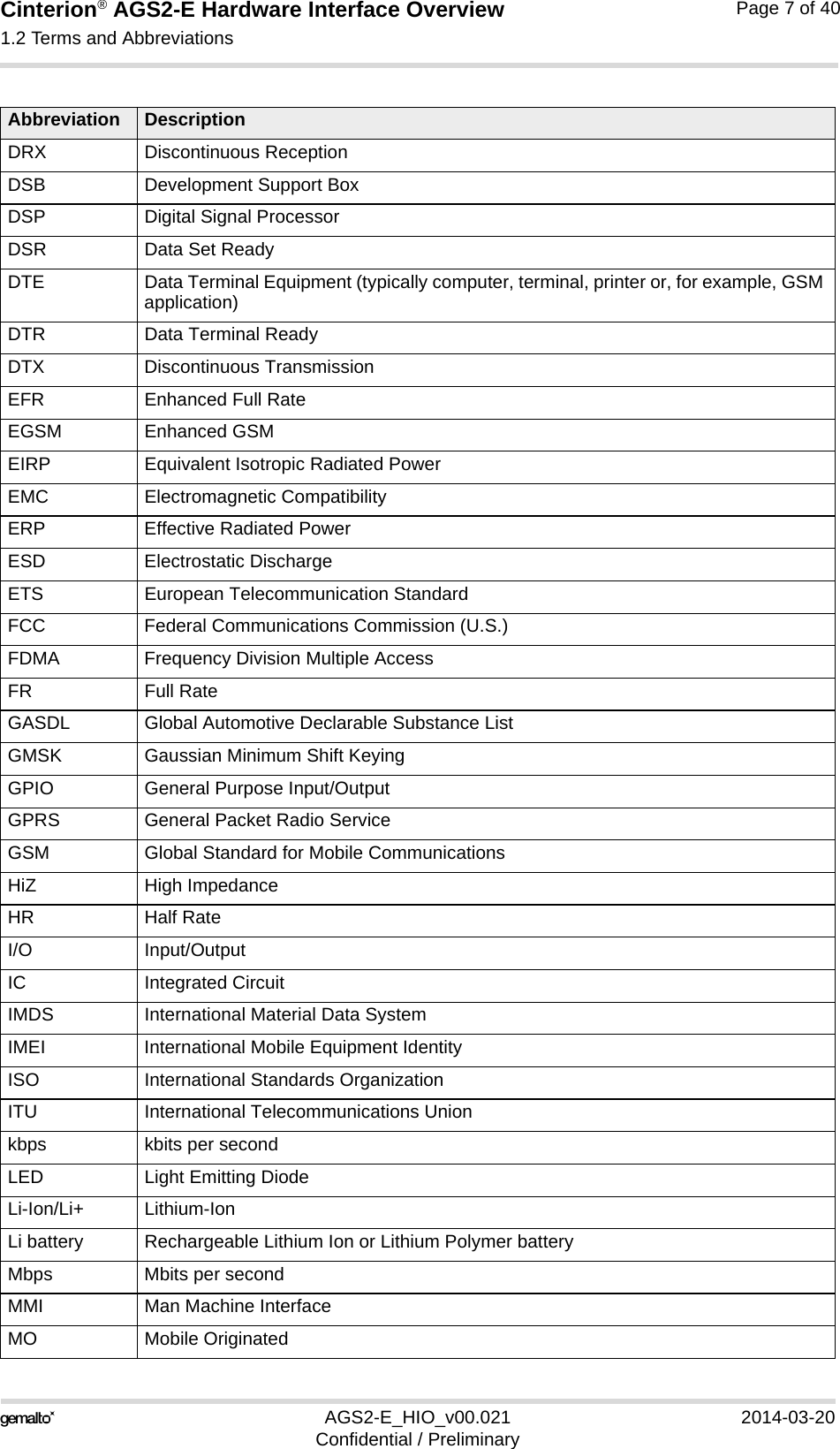
![Cinterion® AGS2-E Hardware Interface Overview1 Introduction14AGS2-E_HIO_v00.021 2014-03-20Confidential / PreliminaryPage 6 of 401 IntroductionThis document1 describes the hardware of the Gemalto M2M Cinterion® AGS2-E module that connects to the cellular device application and the air interface. It helps you quickly retrieve in-terface specifications, electrical and mechanical details and information on the requirements to be considered for integrating further components.1.1 Related Documents[1] Cinterion® AGS2-E AT Command Set[2] Application Note 48: SMT Module Integration for AGS2-E[3] AGS2-E MPE calculation - Test report (Maximum Permissible Exposure)1.2 Terms and Abbreviations1. The document is effective only if listed in the appropriate Release Notes as part of the technicaldocumentation delivered with your Gemalto M2M product.Abbreviation DescriptionADC Analog-to-digital converterAGC Automatic Gain ControlANSI American National Standards InstituteARFCN Absolute Radio Frequency Channel NumberARP Antenna Reference PointASC0/ASC1 Asynchronous Controller. Abbreviations used for first and second serial interface of AGS2-EB Thermistor ConstantBER Bit Error RateBTS Base Transceiver StationCB or CBM Cell Broadcast MessageCE Conformité Européenne (European Conformity)CHAP Challenge Handshake Authentication ProtocolCPU Central Processing UnitCS Coding SchemeCSD Circuit Switched DataCTS Clear to SendDAC Digital-to-Analog ConverterDAI Digital Audio InterfacedBm0 Digital level, 3.14dBm0 corresponds to full scale, see ITU G.711, A-lawDCE Data Communication Equipment (typically modems, e.g. Gemalto M2M module)DCS 1800 Digital Cellular System, also referred to as PCN](https://usermanual.wiki/THALES-DIS-AlS-Deutschland/AGS2-E/User-Guide-2261031-Page-6.png)
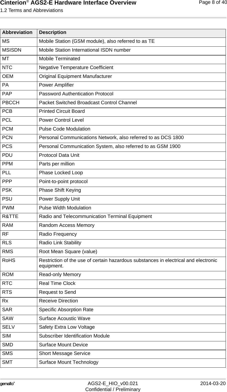
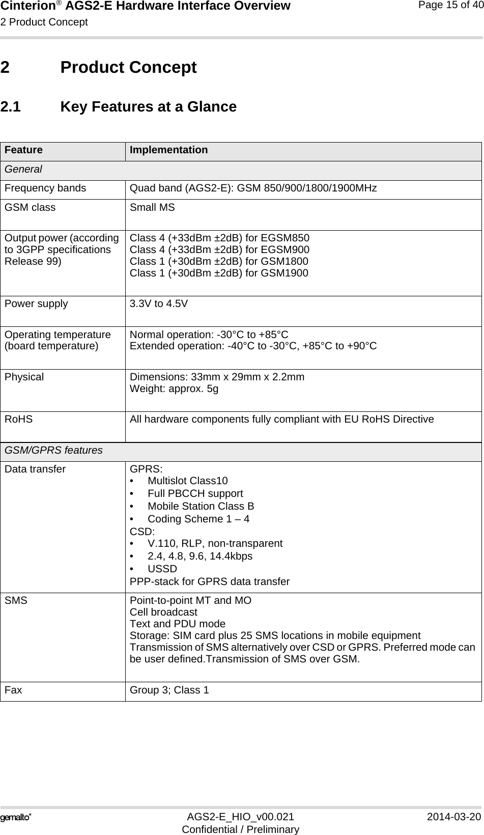
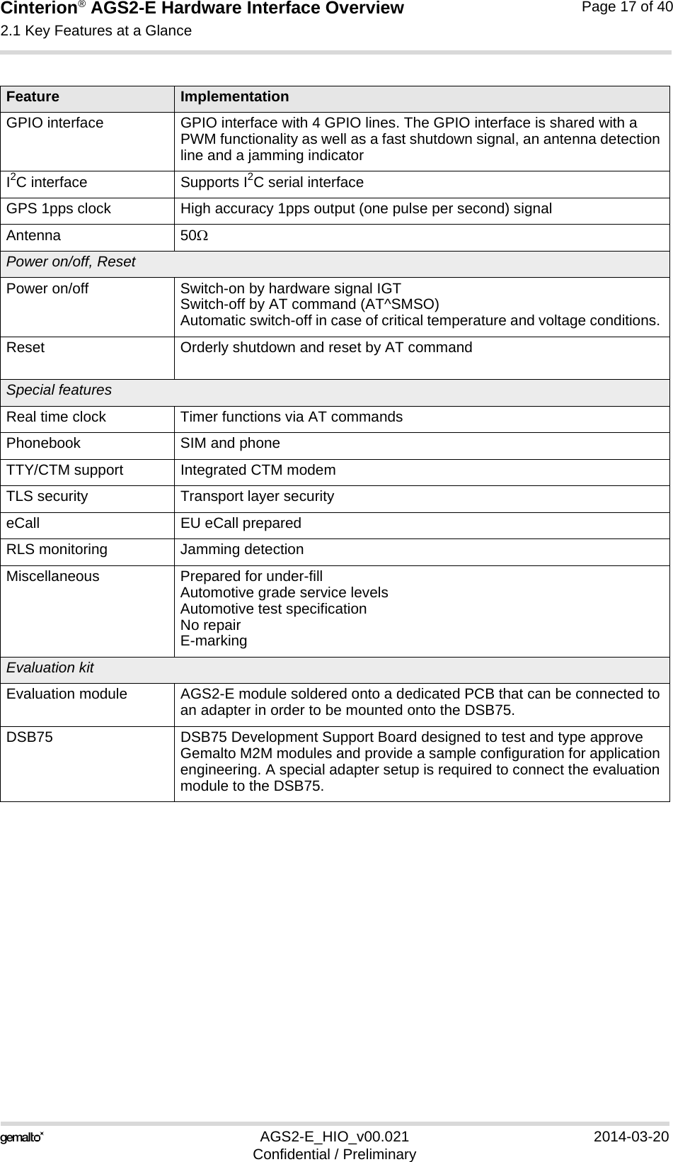
![Cinterion® AGS2-E Hardware Interface Overview2.1 Key Features at a Glance18AGS2-E_HIO_v00.021 2014-03-20Confidential / PreliminaryPage 16 of 40Audio Speech codecs:• Half rate HR (ETS 06.20)• Full rate FR (ETS 06.10) • Enhanced full rate EFR (ETS 06.50/06.60/06.80)• Adaptive Multi Rate AMRHandsfree operation (VDA), echo cancellation, noise suppression, 7 different ringing tones/melodiesVoice prompts GNSS FeaturesProtocol NMEAModes Standalone GNSSGeneral Power saving modesPower supply for an active antennaGPS 1pps clock 1 pulse per second synchronized with GPS timeSoftwareAT commands Hayes 3GPP TS 27.007, TS 27.005, Gemalto M2MAT commands for RIL compatibilityMicrosoft™ compatibility RIL for Pocket PC and SmartphoneSIM Application Toolkit SAT Release 99TCP/IP stack Access by AT commandsFirmware update Generic update from host application over ASC0.InterfacesModule interface Surface mount device with solderable connection pads (SMT application interface). Land grid array (LGA) technology ensures high solder joint reliability and provides the possibility to use an optional module mounting socket.For more information on how to integrate SMT modules see also [2]. This application note comprises chapters on module mounting and application layout issues as well as on additional SMT application development equip-ment.1 serial interfaces ASC0:• 8-wire modem interface with status and control lines, unbalanced, asyn-chronous• Adjustable baud rates: 300bps to 230,400bps• Autobauding: 1,200bps to 230,400bps• Supports RTS0/CTS0 hardware handshake and software XON/XOFFflow control.• Multiplex ability according to GSM 07.10 Multiplexer Protocol.Audio 1 analog interface (with microphone feeding)1 digital interface (PCM)UICC interface Supported SIM/USIM cards: 3V, 1.8V External SIM card reader has to be connected via interface connector (note that card reader is not part of AGS2-E)Feature Implementation](https://usermanual.wiki/THALES-DIS-AlS-Deutschland/AGS2-E/User-Guide-2261031-Page-16.png)
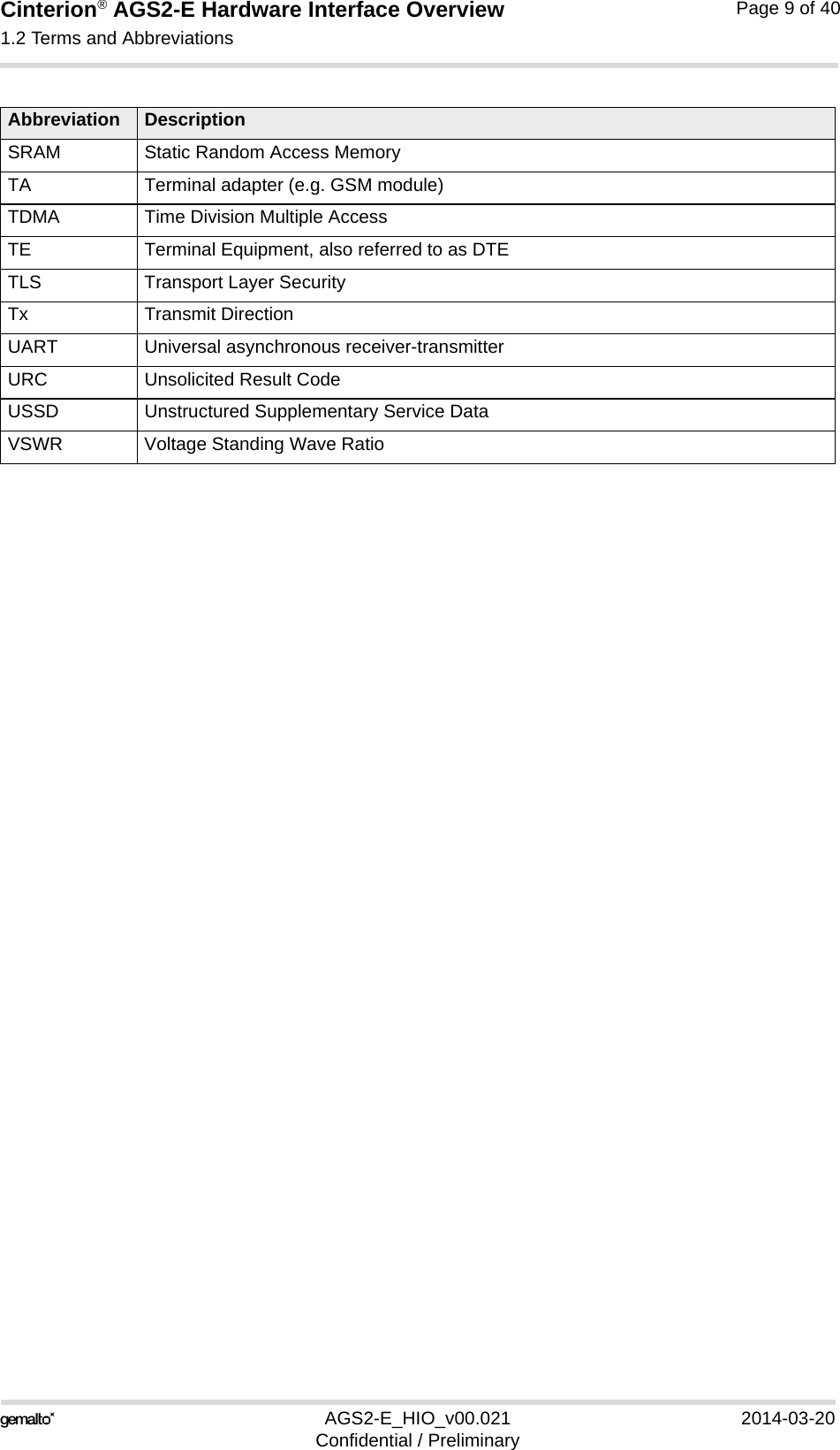
![Cinterion® AGS2-E Hardware Interface Overview3.5 Serial Interface ASC027AGS2-E_HIO_v00.021 2014-03-20Confidential / PreliminaryPage 24 of 403.5 Serial Interface ASC0AGS2-E offers an 8-wire unbalanced, asynchronous modem interface ASC0 conforming toITU-T V.24 protocol DCE signalling. The electrical characteristics do not comply with ITU-TV.28. The voltage level of the ASC0 interface is configured to 1.8V. AGS2-E is designed for use as a DCE. Based on the conventions for DCE-DTE connections itcommunicates with the customer application (DTE) using the following signals:• Port TXD @ application sends data to the module’s TXD0 signal line• Port RXD @ application receives data from the module’s RXD0 signal lineFigure 3: Serial interface ASC0Features:• Includes the data lines TXD0 and RXD0, the status lines RTS0 and CTS0 and, in addition,the modem control lines DTR0, DSR0, DCD0 and RING0. • ASC0 is primarily designed for controlling voice calls, transferring CSD, fax and GPRS dataand for controlling the GSM module with AT commands. Also, the GNSS NMEA datastream is internally routed to the ASC0 interface.• The DTR0 signal will only be polled once per second from the internal firmware of AGS2-E. • The RING0 signal serves to indicate incoming calls and other types of URCs (UnsolicitedResult Code). It can also be used to send pulses to the host application, for example towake up the application from power saving state. See [1] for details on how to configure theRING0 line by AT^SCFG.• Configured for 8 data bits, no parity and 1 stop bit.• ASC0 can be operated at fixed bit rates from 300bps to 230,400bps.• Autobauding supports bit rates from 1,200bps to 230,400bps. • Supports RTS0/CTS0 hardware flow control and XON/XOFF software flow control.](https://usermanual.wiki/THALES-DIS-AlS-Deutschland/AGS2-E/User-Guide-2261031-Page-24.png)
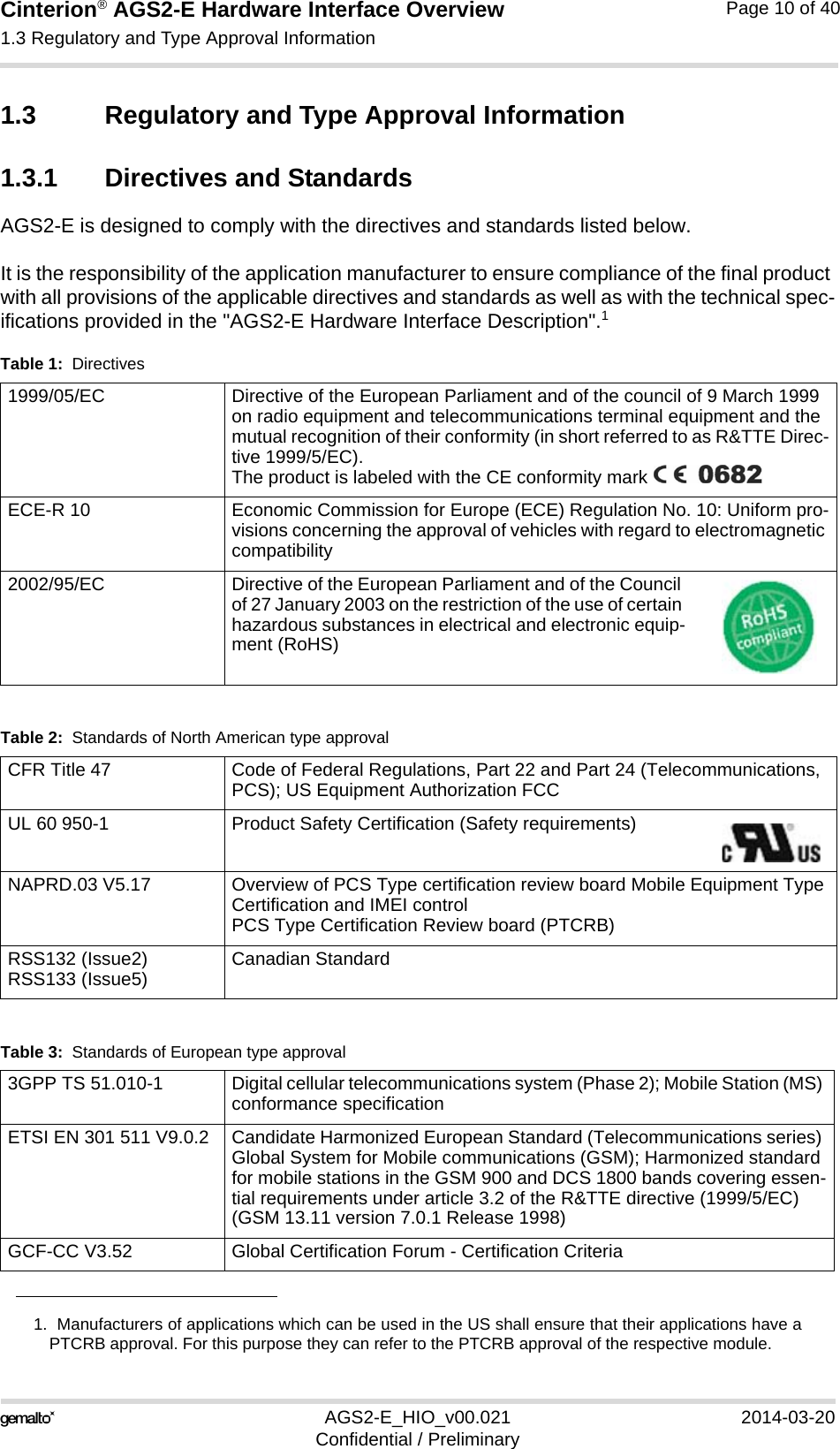
![Cinterion® AGS2-E Hardware Interface Overview4 GNSS Receiver27AGS2-E_HIO_v00.021 2014-03-20Confidential / PreliminaryPage 27 of 404 GNSS ReceiverAGS2-E integrates a GPS receiver that offers the full performance of GPS technology. The GPS receiver is able to continuously track all satellites in view, thus providing accurate satellite position data.The integrated GPS receiver supports the NMEA protocol via ASC0 interface. NMEA is a com-bined electrical and data specification for communication between various (marine) electronic devices including GPS receivers. It has been defined and controlled by the US based National Marine Electronics Association. For more information on the NMEA Standard please refer to http://www.nmea.org.Depending on the receiver’s knowledge of last position, current time and ephemeris data, the receiver’s startup time (i.e., TTFF = Time-To-First-Fix) may vary: If the receiver has no knowl-edge of its last position or time, a startup takes considerably longer than if the receiver has still knowledge of its last position, time and almanac or has still access to valid ephimeris data and the precise time. By default, the GPS receiver is switched off. It has to be switched on and configured using AT commands (AT^SGPSC; see [1]). GPS 1pps Clock:AGS2-E provides a high accuracy 1pps output (one pulse per second) signal, synchronized with the GPS time. The 1pps output can be used by an external application as a reference to generate accurate high-frequency clocks. A specific design however has to address the short-term jitter affecting the 1pps signal. As a general rule, the divided system clock is synchronized with the GPS 1pps for the long-term accuracy. The deviation is less than 50ns.The 1pps signal is based on the almost-perfect timing of the satellite. But as the satellite moves, the distance to it will increase or decrease. This change in distance will produce a change in the 1pps signal, because the light has to travel a different distance each time.To compensate for this effect the GNSS (Global Navigation Satellite System) has to know its position. Then it is able to correct signal effects (mainly distance but there are more). Therefore, at least three satellites are required (better four).](https://usermanual.wiki/THALES-DIS-AlS-Deutschland/AGS2-E/User-Guide-2261031-Page-27.png)
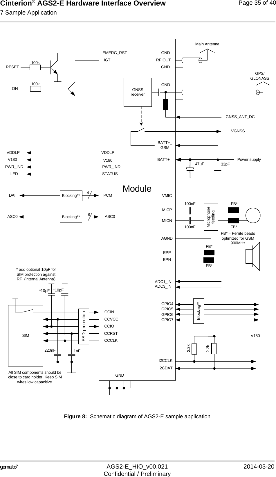
![Cinterion® AGS2-E Hardware Interface Overview7 Sample Application35AGS2-E_HIO_v00.021 2014-03-20Confidential / PreliminaryPage 34 of 407 Sample ApplicationFigure 8 shows a typical example of how to integrate a AGS2-E module with an application.Usage of the various host interfaces depends on the desired features of the application.The analog audio interface demonstrates the balanced connection of microphone and ear-piece. This solution is particularly well suited for internal transducers.Because of the very low power consumption design, current flowing from any other source intothe module circuit must be avoided, for example reverse current from high state external controllines. Therefore, the controlling application must be designed to prevent reverse current flow.Otherwise there is the risk of undefined states of the module during startup and shutdown oreven of damaging the module.Because of the high RF field density inside the module, it cannot be guaranteed that no selfinterference might occur, depending on frequency and the applications grounding concept. ex-cluded that in some applications dependant on the grounding concept of the customer. The po-tential interferers may be minimized by placing small capacitors (47pF) at suspected lines (e.g.RXD0, PCM_CLK, VDDLP, and IGT). While developing SMT applications it is strongly recommended to provide test pointsfor certain signals, i.e., lines to and from the module - for debug and/or test purposes.The SMT application should allow for an easy access to these signals. For details onhow to implement test points see [2].The EMC measures are best practice recommendations. In fact, an adequate EMC strategy foran individual application is very much determined by the overall layout and, especially, the po-sition of components. For example, mounting the internal acoustic transducers directly on thePCB eliminates the need to use the ferrite beads shown in the sample schematic. Please note that AGS2-E is not intended for use with cables longer than 3m.DisclaimerNo warranty, either stated or implied, is provided on the sample schematic diagram shown inFigure 8 and the information detailed in this section. As functionality and compliance with na-tional regulations depend to a great amount on the used electronic components and the indi-vidual application layout manufacturers are required to ensure adequate design and operatingsafeguards for their products using AGS2-E modules.](https://usermanual.wiki/THALES-DIS-AlS-Deutschland/AGS2-E/User-Guide-2261031-Page-34.png)
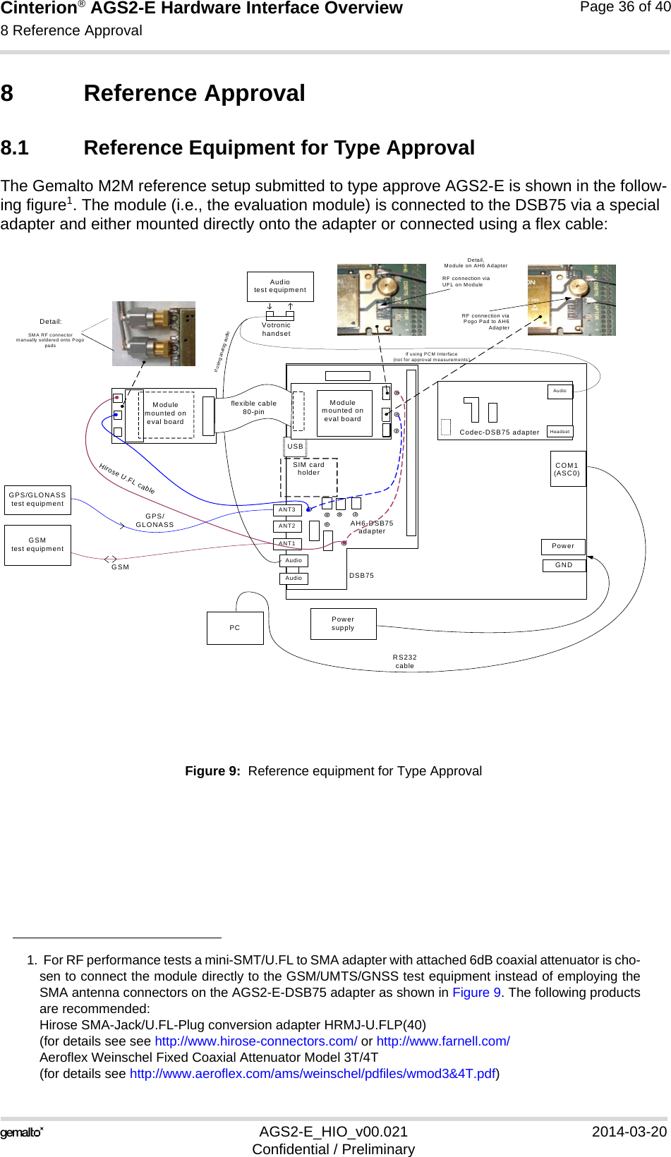
![Cinterion® AGS2-E Hardware Interface Overview8.2 Compliance with FCC and IC Rules and Regulations37AGS2-E_HIO_v00.021 2014-03-20Confidential / PreliminaryPage 37 of 408.2 Compliance with FCC and IC Rules and RegulationsThe Equipment Authorization Certification for the Gemalto M2M reference application de-scribed in Section 8.1 will be registered under the following identifiers:FCC Identifier: QIPAGS2-EIndustry Canada Certification Number: 7830A-AGS2EGranted to Gemalto M2M GmbH Manufacturers of mobile or fixed devices incorporating AGS2-E modules are authorized to use the FCC Grants and Industry Canada Certificates of the AGS2-E modules for their own final products according to the conditions referenced in these documents. In this case, an FCC/ IC label of the module shall be visible from the outside, or the host device shall bear a second label stating "Contains FCC ID QIPAGS2-E", and accordingly “Contains IC 7830A-AGS2E“.The integration is limited to fixed or mobile categorised host devices, where a separation dis-tance between the antenna and any person of min. 20cm can be assured during normal oper-ating conditions. For mobile and fixed operation configurations the antenna gain, including cable loss, must not exceed the limits 6.71dBi (850 MHz) and 2.23dBi (1900 MHz). See [3].IMPORTANT: Manufacturers of portable applications incorporating AGS2-E modules are required to have their final product certified and apply for their own FCC Grant and Industry Canada Certificate related to the specific portable mobile. This is mandatory to meet the SAR requirements for por-table mobiles (see Section 1.3.2 for detail).Changes or modifications not expressly approved by the party responsible for compliance could void the user's authority to operate the equipment.Note: This equipment has been tested and found to comply with the limits for a Class B digital device, pursuant to part 15 of the FCC Rules. These limits are designed to provide reasonable protec-tion against harmful interference in a residential installation. This equipment generates, uses and can radiate radio frequency energy and, if not installed and used in accordance with the instructions, may cause harmful interference to radio communications. However, there is no guarantee that interference will not occur in a particular installation. If this equipment does cause harmful interference to radio or television reception, which can be determined by turning the equipment off and on, the user is encouraged to try to correct the interference by one or more of the following measures:• Reorient or relocate the receiving antenna.• Increase the separation between the equipment and receiver.• Connect the equipment into an outlet on a circuit different from that to which the receiver isconnected.• Consult the dealer or an experienced radio/TV technician for help.The manufacturer is responsible for ensuring that after the module is installed and operational the host continues to be compliant with the Part 15B unintentional radiator requirements.](https://usermanual.wiki/THALES-DIS-AlS-Deutschland/AGS2-E/User-Guide-2261031-Page-37.png)