THALES DIS AlS Deutschland ALAS6A-US Data Module User Manual alas6a us hid
Gemalto M2M GmbH Data Module alas6a us hid
UserManual.wiki
>
THALES DIS AlS Deutschland
>
ALAS6A US User Manual
user manual
Navigation menu
Upload a User Manual
Namespaces
Wiki Guide
HTML
PDF
Info
Views
User Manual
Discussion / Help
Navigation
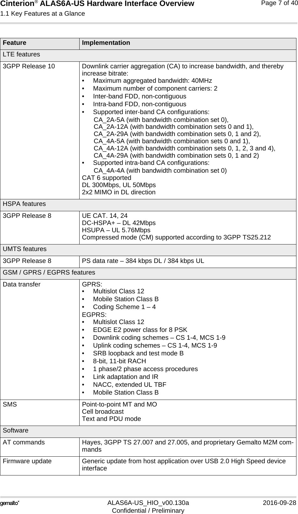
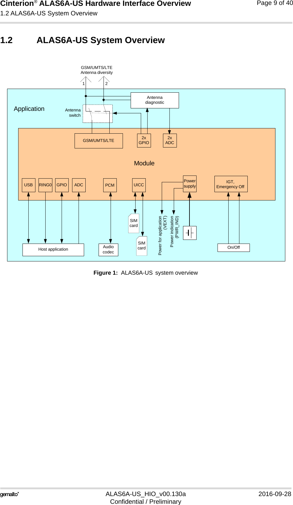
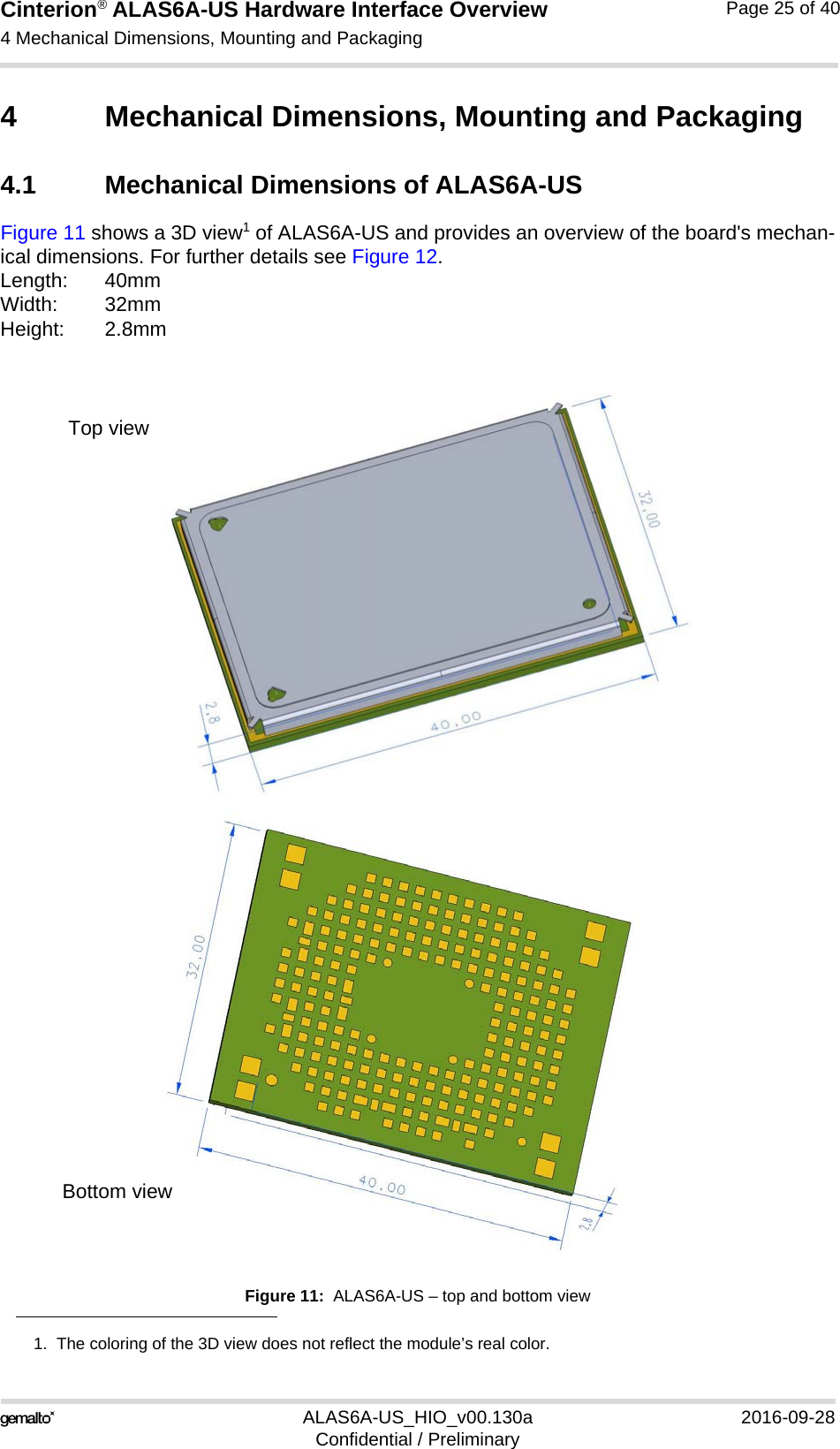
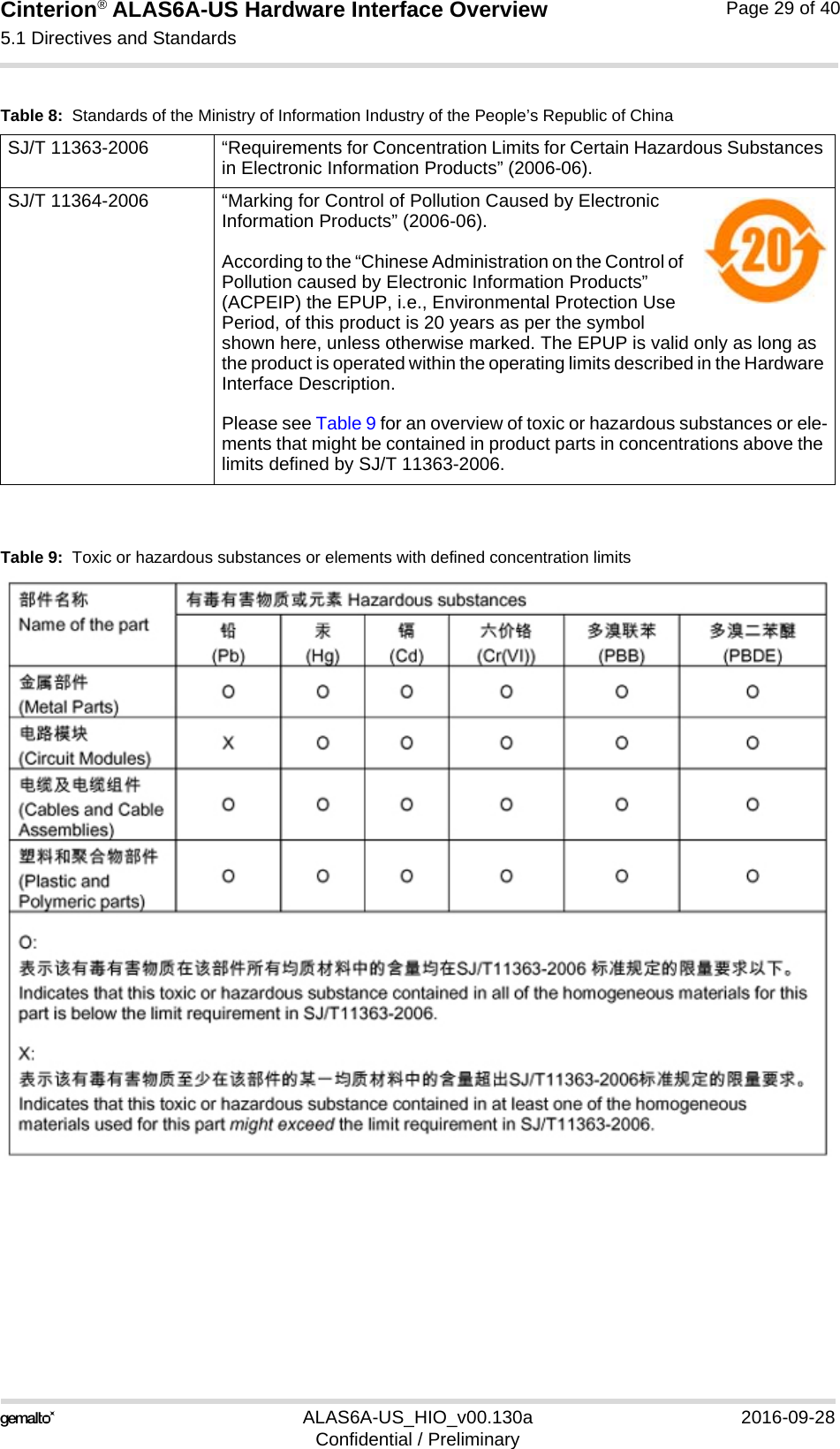
![Cinterion® ALAS6A-US Hardware Interface Overview1.1 Key Features at a Glance9ALAS6A-US_HIO_v00.130a 2016-09-28Confidential / PreliminaryPage 8 of 40InterfacesModule interface Surface mount device with solderable connection pads (SMT application interface).Land grid array (LGA) technology ensures high solder joint reliability and provides the possibility to use an optional module mounting socket.For more information on how to integrate SMT modules see also [3]. This application note comprises chapters on module mounting and application layout issues as well as on additional SMT application development equip-ment.Antenna 50. GSM/UMTS/LTE main antenna, UMTS/LTE Diversity/MIMO antennaUSB USB 2.0 High Speed (480Mbit/s) device interface orUSB 3.0 Super Speed (5Gbit/s) device interfaceUICC interface 2 UICC interfaces (switchable)Supported chip cards: UICC/SIM/USIM 3V, 1.8VAudio 1 digital interface (PCM)RING0 Signal line to indicate incoming calls and other types of URCsPower on/off, ResetPower on/off Switch-on by hardware signal IGTSwitch-off by AT command (AT^SMSO) or IGT (option)Automatic switch-off in case of critical temperature or voltage conditionsReset Orderly shutdown and reset by AT commandEmergency-off Emergency-off by hardware signal EMERG_OFF Special FeaturesAntenna SAIC (Single Antenna Interference Cancellation) / DARP (Downlink Advanced Receiver Performance)Rx Diversity (receiver type 3i - 64-QAM) / MIMOGPIO 10 I/O pins of the application interface programmable as GPIO.Programming is done via AT commands.ADC inputs Analog-to-Digital Converter with two unbalanced analog inputs for (exter-nal) antenna diagnosisEvaluation kitEvaluation module ALAS6A-US module soldered onto a dedicated PCB that can be con-nected to the ALAS6A-DSB75 adapter in order to be mounted onto the DSB75.ALAS6A-DSB75 adapter A special adapter required to connect the ALAS6A-US evaluation module to the DSB75.DSB75 DSB75 Development Support Board designed to test and type approve Gemalto M2M modules and provide a sample configuration for application engineering. Feature Implementation](https://usermanual.wiki/THALES-DIS-AlS-Deutschland/ALAS6A-US/User-Guide-3156056-Page-8.png)
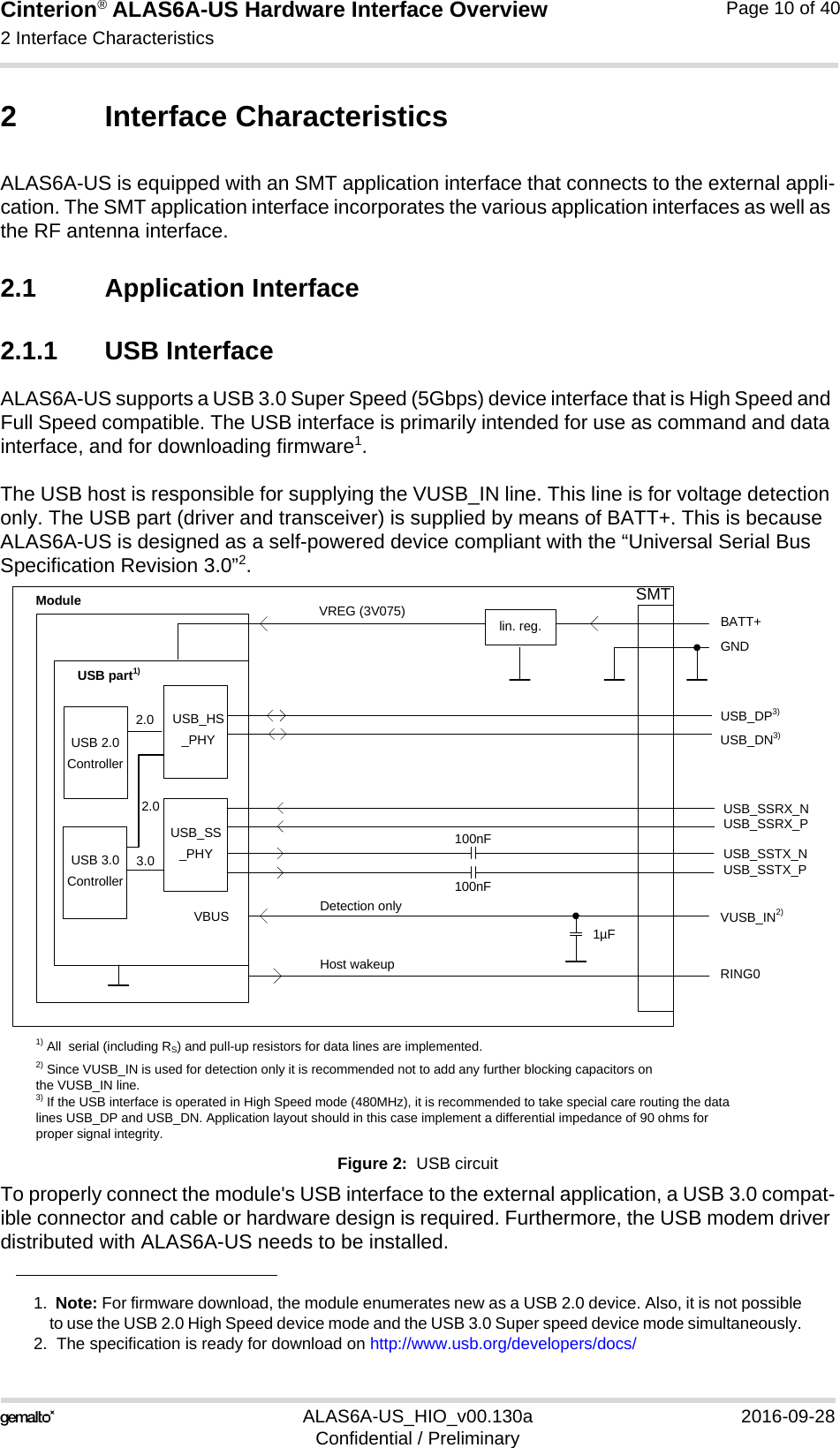
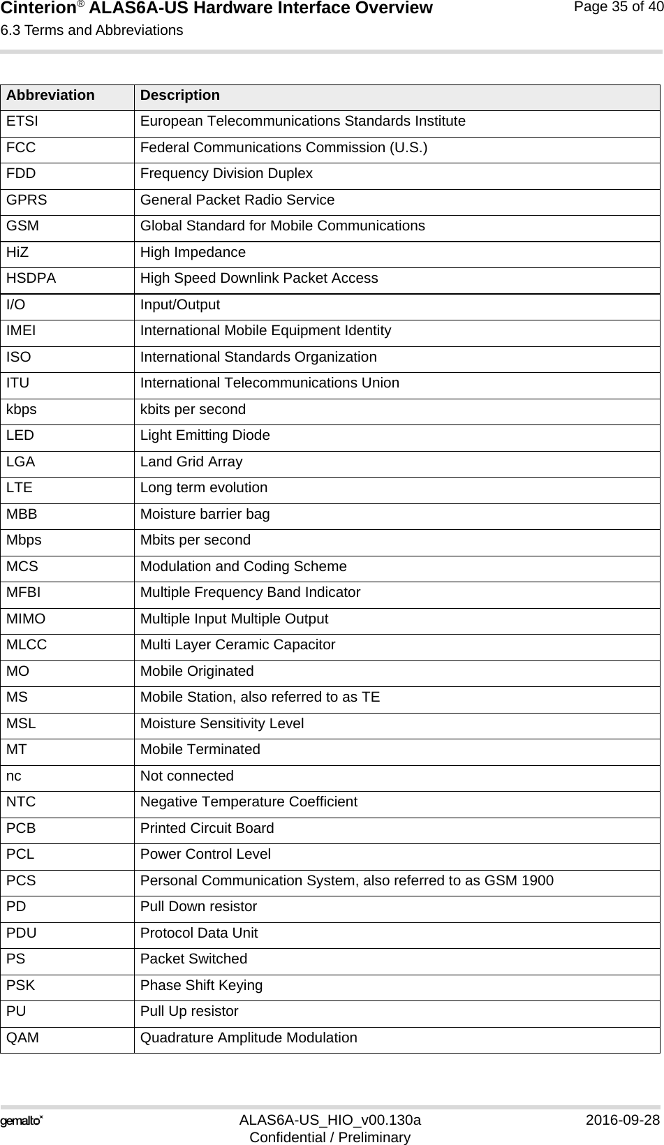
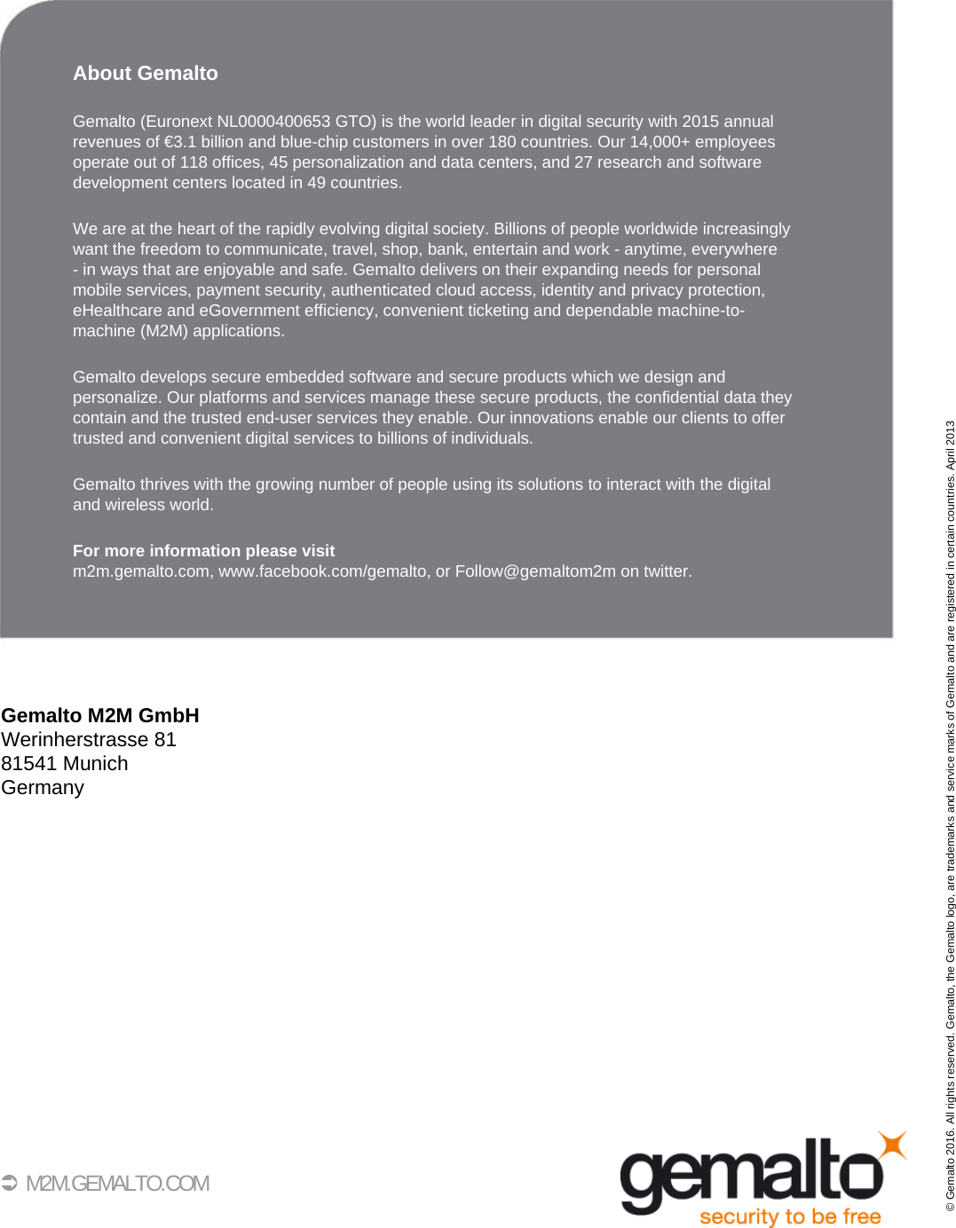
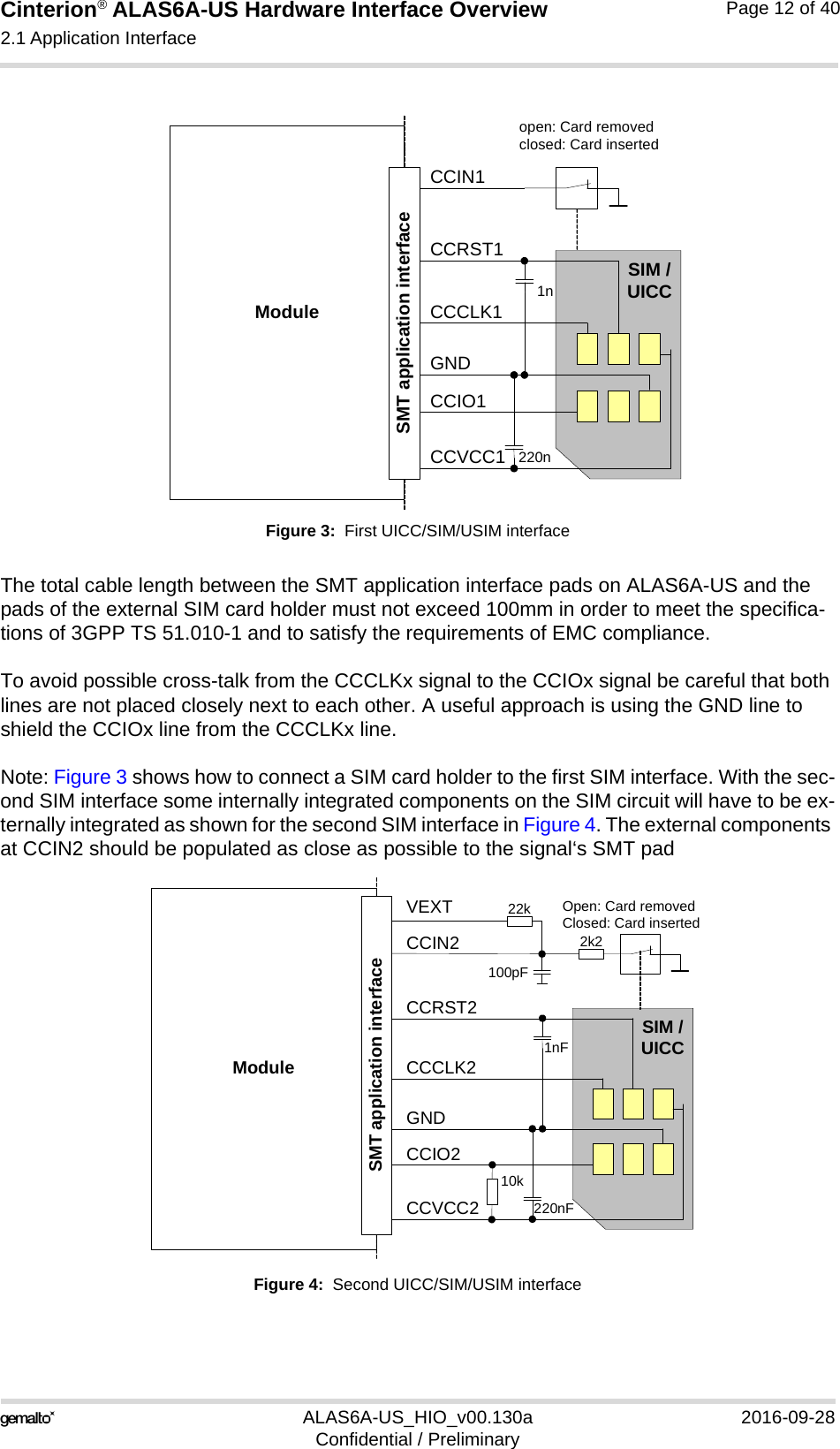
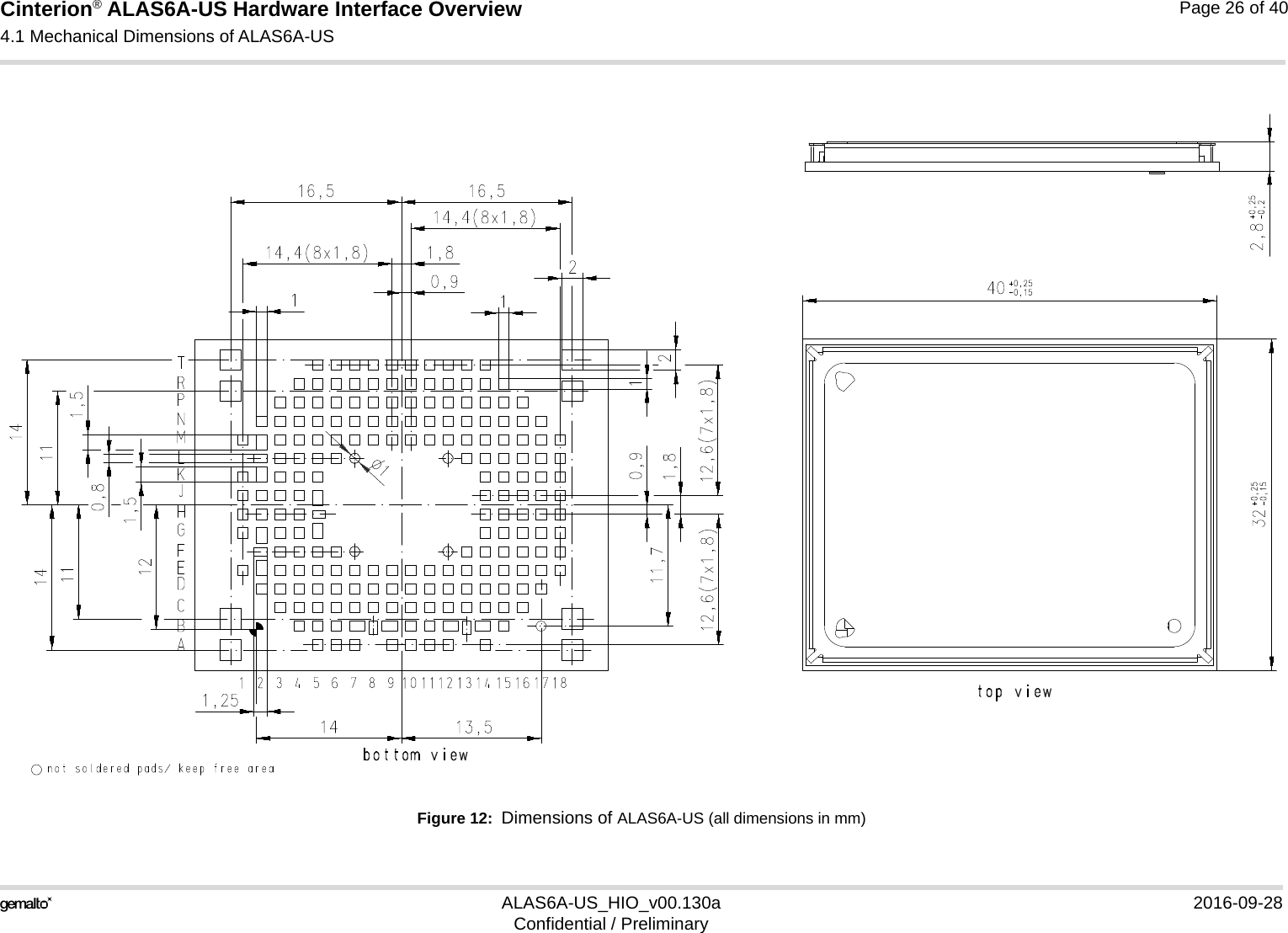
![Cinterion® ALAS6A-US Hardware Interface Overview2.1 Application Interface22ALAS6A-US_HIO_v00.130a 2016-09-28Confidential / PreliminaryPage 11 of 402.1.2 UICC/SIM/USIM InterfaceALAS6A-US has two UICC/SIM/USIM interfaces compatible with the 3GPP 31.102 and ETSI 102 221. These are wired to the host interface in order to be connected to an external SIM card holder. Five pads on the SMT application interface are reserved for each of the two SIM inter-faces.The UICC/SIM/USIM interface supports 3V and 1.8V SIM cards. The CCINx signal serves to detect whether a tray (with SIM card) is present in the card holder. Using the CCINx signal is mandatory for compliance with the GSM 11.11 recommendation if the mechanical design of the host application allows the user to remove the SIM card during operation. To take advantage of this feature, an appropriate SIM card detect switch is required on the card holder. For example, this is true for the model supplied by Molex, which has been tested to operate with ALAS6A-US and is part of the Gemalto M2M reference equipment sub-mitted for type approval. See Chapter 7 for Molex ordering numbers.Note: No guarantee can be given, nor any liability accepted, if loss of data is encountered after removing the SIM card during operation. Also, no guarantee can be given for properly initializ-ing any SIM card that the user inserts after having removed the SIM card during operation. In this case, the application must restart ALAS6A-US.By default, only the 1st SIM interface is available and can be used. Using the AT command AT^SCFG=”SIM/CS” it is possible to switch between the two SIM interfaces. Command set-tings are non-volatile - for details see [1].Table 1: Signals of the SIM interface (SMT application interface)Signal DescriptionGND Ground connection for SIM interfaces. Optionally a separate SIM ground line using e.g., pad P12, may be used to improve EMC.CCCLK1CCCLK2 Chipcard clock lines for 1st and 2nd SIM interface.CCVCC1CCVCC2 SIM supply voltage lines for 1st and 2nd SIM interface.CCIO1CCIO2 Serial data lines for 1st and 2nd SIM interface, input and output.CCRST1CCRST2 Chipcard reset lines for 1st and 2nd SIM interface.CCIN1CCIN2 Input on the baseband processor for detecting a SIM card tray in the holder. If the SIM is removed during operation the SIM interface is shut down immediately to prevent destruc-tion of the SIM. The CCINx signal is active low.The CCINx signal is mandatory for applications that allow the user to remove the SIM card during operation. The CCINx signal is solely intended for use with a SIM card. It must not be used for any other purposes. Failure to comply with this requirement may invalidate the type approval of ALAS6A-US.](https://usermanual.wiki/THALES-DIS-AlS-Deutschland/ALAS6A-US/User-Guide-3156056-Page-11.png)
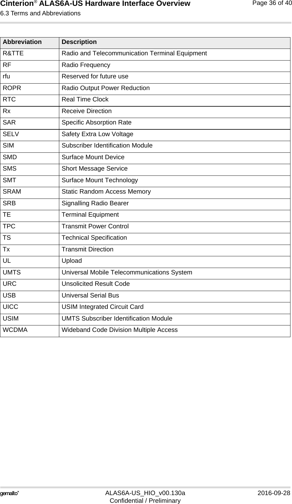
![Cinterion® ALAS6A-US Hardware Interface Overview2.1 Application Interface22ALAS6A-US_HIO_v00.130a 2016-09-28Confidential / PreliminaryPage 14 of 402.1.6 Control Signals2.1.6.1 PWR_IND SignalPWR_IND notifies the on/off state of the module. High state of PWR_IND indicates that the module is switched off. The state of PWR_IND immediately changes to low when IGT is pulled low. For state detection an external pull-up resistor is required.2.1.6.2 Behavior of the RING0 LineThe RING0 line serves to indicate incoming calls and other types of URCs (Unsolicited Result Code).The RING0 line behavior and usage can be configured by AT command. For details see [1]: AT^SCFG.2.1.6.3 Low Current IndicatorA low current indication is optionally available over a GPIO line. By default, low current indica-tion is disabled and the GPIO pads can be configured and employed as usual. For a GPIO pad to work as a low current indicator the feature has to be enabled by AT com-mand (see [1]: AT^SCFG: MEopMode/PowerMgmt/LCI). By default, the GPIO6 pad is config-ured as LCI_IND signal.If enabled, the GPIOx/LCI_IND signal is high when the module is sleeping. 2.1.6.4 Remote WakeupIf no call, data or message transfer is in progress, the external host application may shut downits own module interfaces or other components in order to save power. If a call, data, or otherrequest (URC) arrives, the external application can be notified of this event and be woken upagain by a state transition of a configurable remote wakeup line. Available as remote wakeuplines are all GPIO signals as well as the RING0 line. Please refer to [1]: AT^SCFG: "Re-moteWakeUp/..." for details on how to configure these lines for defined wakeup events onspecified device interfaces.](https://usermanual.wiki/THALES-DIS-AlS-Deutschland/ALAS6A-US/User-Guide-3156056-Page-14.png)
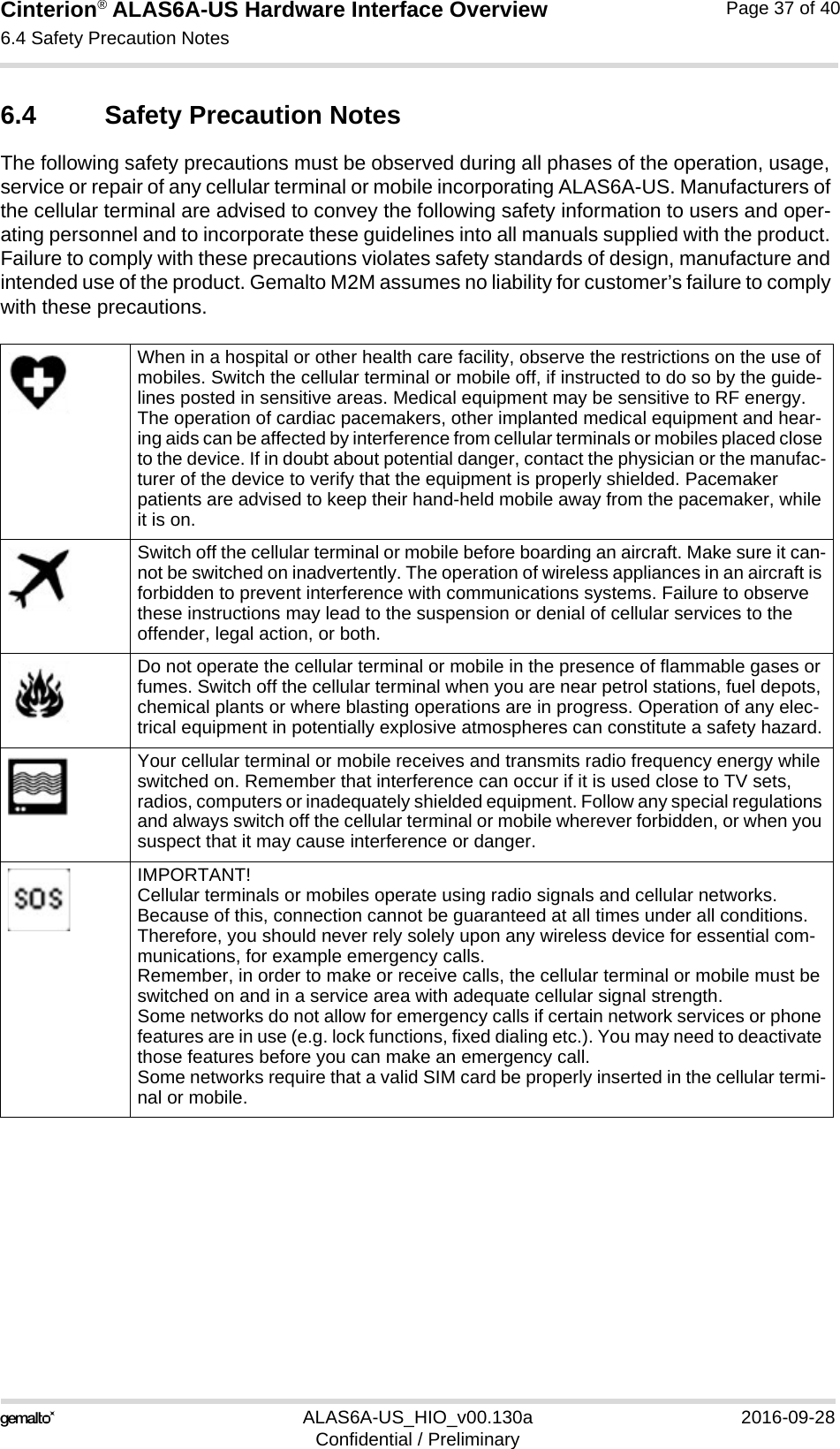
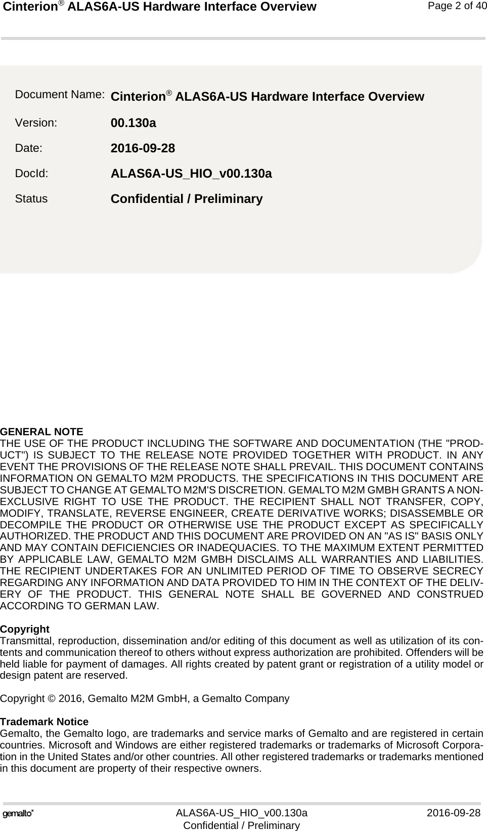
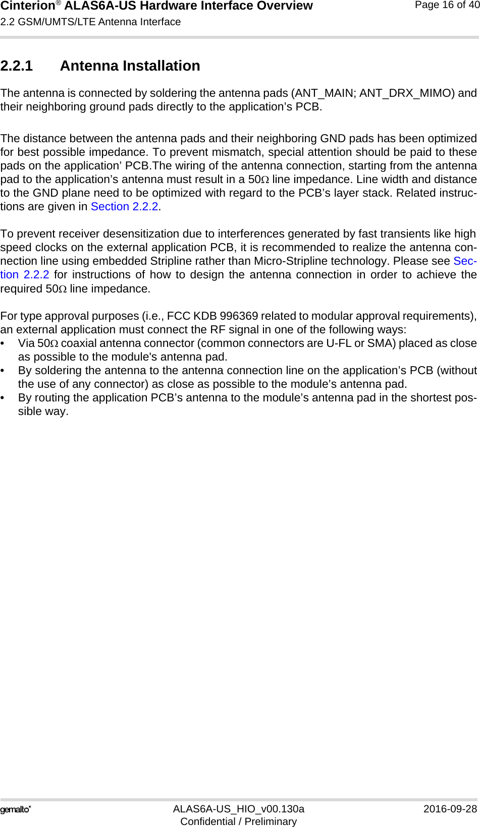
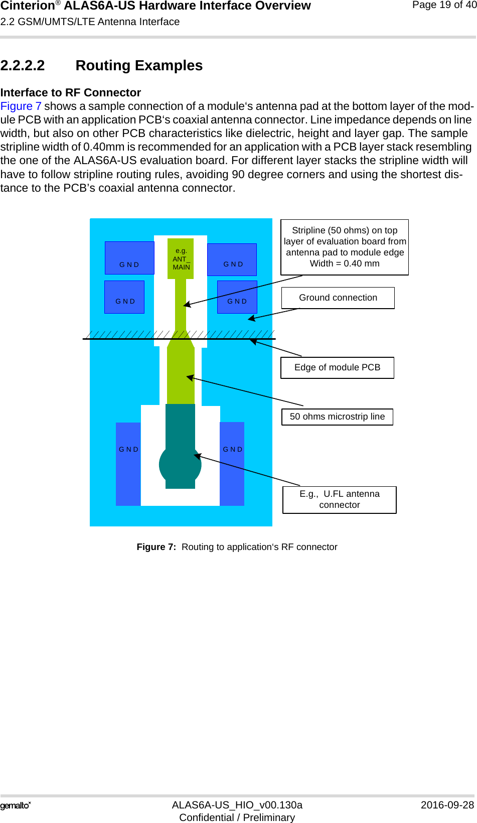
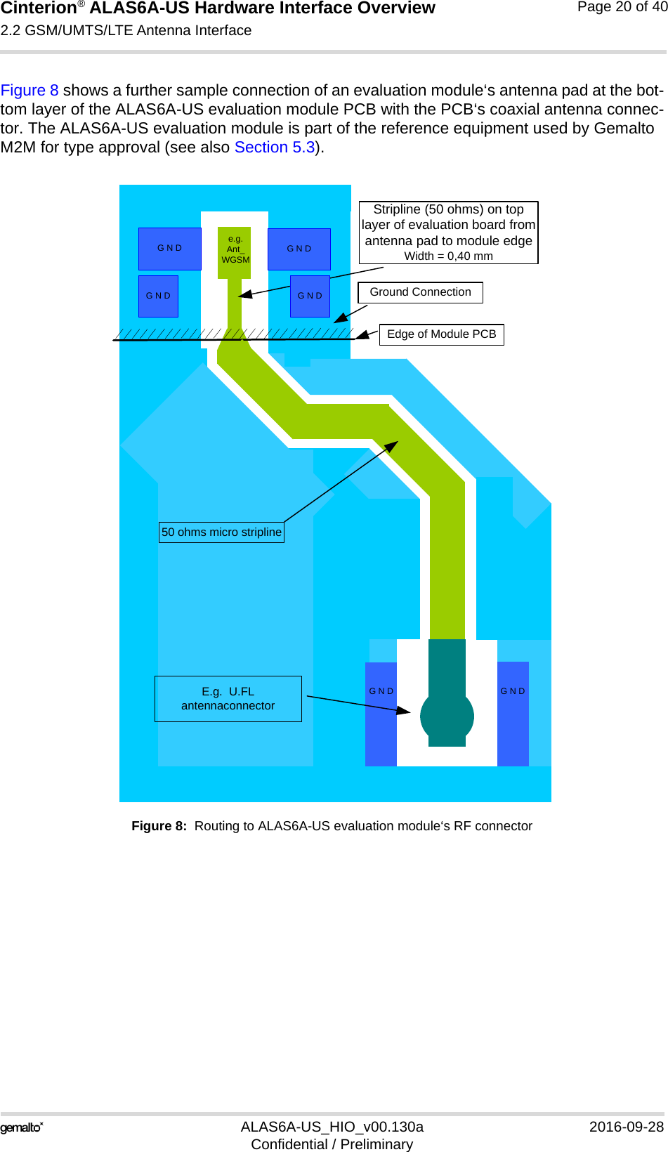
![Cinterion® ALAS6A-US Hardware Interface Overview2.2 GSM/UMTS/LTE Antenna Interface22ALAS6A-US_HIO_v00.130a 2016-09-28Confidential / PreliminaryPage 15 of 402.2 GSM/UMTS/LTE Antenna InterfaceThe ALAS6A-US GSM/UMTS/LTE antenna interface comprises a GSM/UMTS/LTE main an-tenna as well as a UMTS/LTE Rx diversity/MIMO antenna to improve signal reliability and qual-ity1. The interface has an impedance of 50. ALAS6A-US is capable of sustaining a total mismatch at the antenna interface without any damage, even when transmitting at maximum RF power.The external antennas must be matched properly to achieve best performance regarding radi-ated power, modulation accuracy and harmonic suppression. Matching networks are not in-cluded on the ALAS6A-US PCB and should be placed in the host application, if the antenna does not have an impedance of 50.Regarding the return loss ALAS6A-US provides the following values in the active band:1. By delivery default the UMTS/LTE Rx diversity/MIMO antenna is configured as available for the modulesince its usage is mandatory for LTE. Please refer to [1] for details on how to configure antenna settings. Table 2: Return loss in the active bandState of module Return loss of module Recommended return loss of applicationReceive > 8dB > 12dBTransmit not applicable > 12dBIdle < 5dB not applicable](https://usermanual.wiki/THALES-DIS-AlS-Deutschland/ALAS6A-US/User-Guide-3156056-Page-15.png)
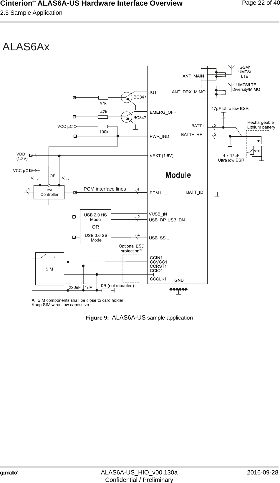
![Cinterion® ALAS6A-US Hardware Interface Overview2.3 Sample Application22ALAS6A-US_HIO_v00.130a 2016-09-28Confidential / PreliminaryPage 21 of 402.3 Sample ApplicationFigure 9 shows a typical example of how to integrate an ALAS6A-US module with an applica-tion. The PWR_IND line is an open collector that needs an external pull-up resistor which connects to the voltage supply VCC µC of the microcontroller. Low state of the open collector pulls the PWR_IND signal low and indicates that the ALAS6A-US module is active, high level notifies the Power Down mode. If the module is in Power Down mode avoid current flowing from any other source into the mod-ule circuit, for example reverse current from high state external control lines. Therefore, the controlling application must be designed to prevent reverse flow.While developing SMT applications it is strongly recommended to provide test pointsfor certain signals, i.e., lines to and from the module - for debug and/or test purposes.The SMT application should allow for an easy access to these signals. For details onhow to implement test points see [3].The EMC measures are best practice recommendations. In fact, an adequate EMC strategy for an individual application is very much determined by the overall layout and, especially, the po-sition of components. Some LGA pads are connected to clocks or high speed data streams that might interfere with the module’s antenna. The RF receiver would then be blocked at certain frequencies (self in-terference). The external application’s PCB tracks connected to these pads should therefore be well shielded or kept away from the antenna. This applies especially to the USB and UICC/SIM interfaces.Disclaimer:No warranty, either stated or implied, is provided on the sample schematic diagram shown in Figure 9 and the information detailed in this section. As functionality and compliance with na-tional regulations depend to a great amount on the used electronic components and the indi-vidual application layout manufacturers are required to ensure adequate design and operating safeguards for their products using ALAS6A-US modules.](https://usermanual.wiki/THALES-DIS-AlS-Deutschland/ALAS6A-US/User-Guide-3156056-Page-21.png)
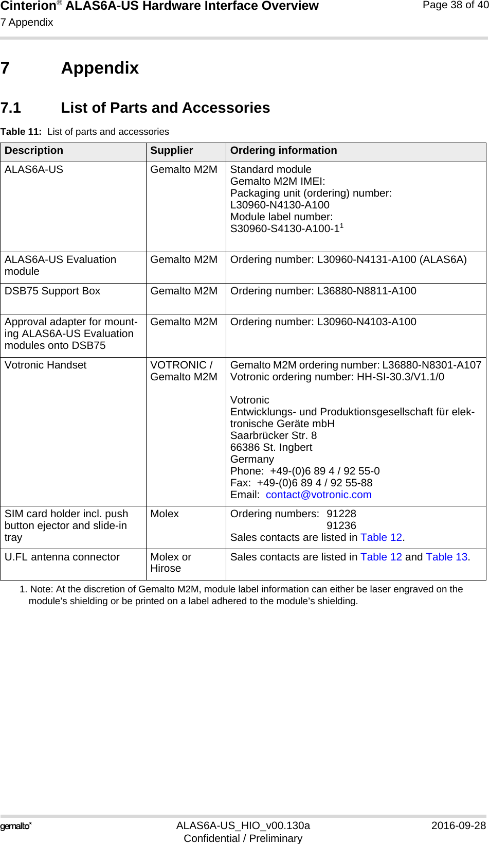
![Cinterion® ALAS6A-US Hardware Interface Overview3 Operating Characteristics24ALAS6A-US_HIO_v00.130a 2016-09-28Confidential / PreliminaryPage 23 of 403 Operating Characteristics3.1 Operating ModesThe table below briefly summarizes the various operating modes referred to throughout the document. Table 3: Overview of operating modesMode FunctionNormal operation GSM / GPRS / UMTS / HSPA /LTE SLEEPPower saving set automatically when no call is in progress and the USB connection is detached. GSM / GPRS / UMTS / HSPA / LTE IDLEPower saving disabled or an USB connection active, but no data trans-fer in progress.GPRS DATA GPRS data transfer in progress. Power consumption depends on net-work settings (e.g. power control level), uplink / downlink data rates and GPRS configuration (e.g. used multislot settings).EGPRS DATA EGPRS data transfer in progress. Power consumption depends on net-work settings (e.g. power control level), uplink / downlink data rates and EGPRS configuration (e.g. used multislot settings).UMTS DATA UMTS data transfer in progress. Power consumption depends on net-work settings (e.g. TPC Pattern) and data transfer rate.HSPA DATA HSPA data transfer in progress. Power consumption depends on net-work settings (e.g. TPC Pattern) and data transfer rate.LTE DATA LTE data transfer in progress. Power consumption depends on network settings (e.g. TPC Pattern) and data transfer rate.Power Down Normal shutdown after sending the AT^SMSO command. Software is not active. Interfaces are not accessible. Operating voltage (connected to BATT+) remains applied. Only a volt-age regulator is active for powering the RTC, as long as operating voltage applied at BATT+ does not drop below approx. 1.4V.Airplane mode Airplane mode shuts down the radio part of the module, causes the module to log off from the GSM/GPRS network and disables all AT commands whose execution requires a radio connection.Airplane mode can be controlled by AT command (see [1]).](https://usermanual.wiki/THALES-DIS-AlS-Deutschland/ALAS6A-US/User-Guide-3156056-Page-23.png)
![Cinterion® ALAS6A-US Hardware Interface Overview6 Document Information37ALAS6A-US_HIO_v00.130a 2016-09-28Confidential / PreliminaryPage 34 of 406 Document Information6.1 Revision HistoryNew document: "Cinterion® ALAS6A-US Hardware Interface Overview" Version 00.130a6.2 Related Documents[1] ALAS6A-US AT Command Set[2] ALAS6A-US Release Note[3] Application Note 48: SMT Module Integration[4] Universal Serial Bus Specification Revision 3.0 [5] Universal Serial Bus Specification Revision 2.0 6.3 Terms and AbbreviationsChapter What is new-- Initial document setup.Abbreviation DescriptionANSI American National Standards InstituteARP Antenna Reference PointCA Carrier AggregationCE Conformité Européene (European Conformity)CS Coding SchemeCS Circuit SwitchedCSD Circuit Switched DataDL Downloaddnu Do not useDRX Discontinuous ReceptionDSB Development Support BoardDTX Discontinuous TransmissionEDGE Enhanced Data rates for GSM EvolutionEGSM Extended GSMEMC Electromagnetic CompatibilityESD Electrostatic DischargeETS European Telecommunication Standard](https://usermanual.wiki/THALES-DIS-AlS-Deutschland/ALAS6A-US/User-Guide-3156056-Page-34.png)