THALES DIS AlS Deutschland BGS2 GSM 850/900/1800/1900 GPRS Module User Manual hio
Gemalto M2M GmbH GSM 850/900/1800/1900 GPRS Module hio
UserManual.wiki
>
THALES DIS AlS Deutschland
>
BGS2 User Manual
08 user manual
Navigation menu
Upload a User Manual
Namespaces
Wiki Guide
HTML
PDF
Info
Views
User Manual
Discussion / Help
Navigation
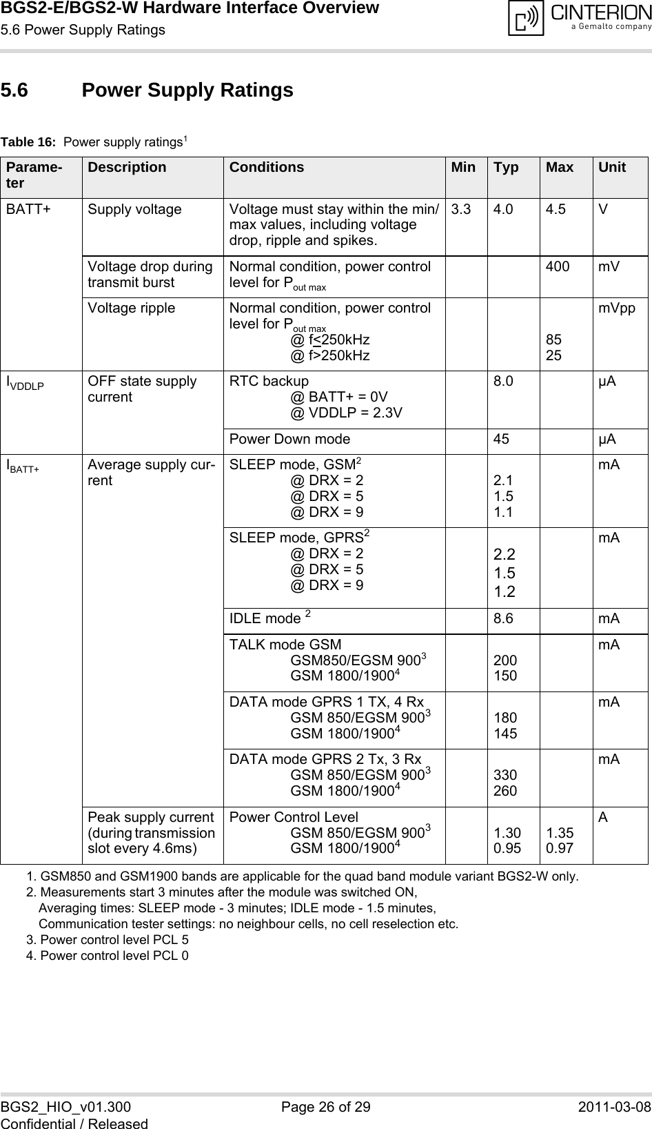
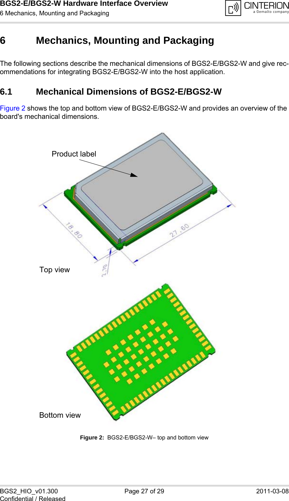
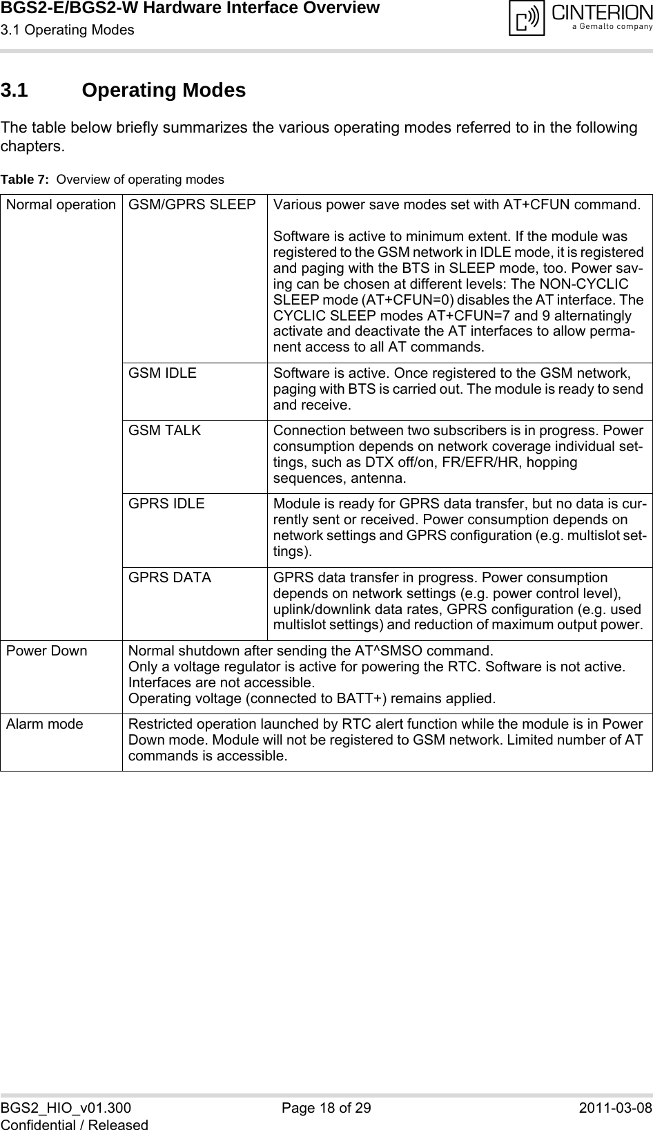
![BGS2-E/BGS2-W Hardware Interface Overview1 Introduction14BGS2_HIO_v01.300 Page 6 of 29 2011-03-08Confidential / Released1 IntroductionThis document1 describes the hardware of the Cinterion BGS2-E/BGS2-W module that con-nects to the cellular device application and the air interface. It helps you quickly retrieve inter-face specifications, electrical and mechanical details and information on the requirements to be considered for integrating further components.1.1 Related Documents[1] BGS2-E/BGS2-W AT Command Set[2] BGS2-E/BGS2-W Release Note1.2 Terms and Abbreviations1. The document is effective only if listed in the appropriate Release Notes as part of the technicaldocumentation delivered with your Cinterion product.Abbreviation DescriptionADC Analog-to-digital converterAGC Automatic Gain ControlANSI American National Standards InstituteARFCN Absolute Radio Frequency Channel NumberARP Antenna Reference PointASC0/ASC1 Asynchronous Controller. Abbreviations used for first and second serial interface of BGS2-E/BGS2-WB Thermistor ConstantBER Bit Error RateBTS Base Transceiver StationCB or CBM Cell Broadcast MessageCE Conformité Européene (European Conformity)CHAP Challenge Handshake Authentication ProtocolCPU Central Processing UnitCS Coding SchemeCSD Circuit Switched DataCTS Clear to SendDAC Digital-to-Analog ConverterDAI Digital Audio InterfacedBm0 Digital level, 3.14dBm0 corresponds to full scale, see ITU G.711, A-lawDCE Data Communication Equipment (typically modems, e.g. Cinterion GSM module)DCS 1800 Digital Cellular System, also referred to as PCN](https://usermanual.wiki/THALES-DIS-AlS-Deutschland/BGS2/User-Guide-1427662-Page-6.png)
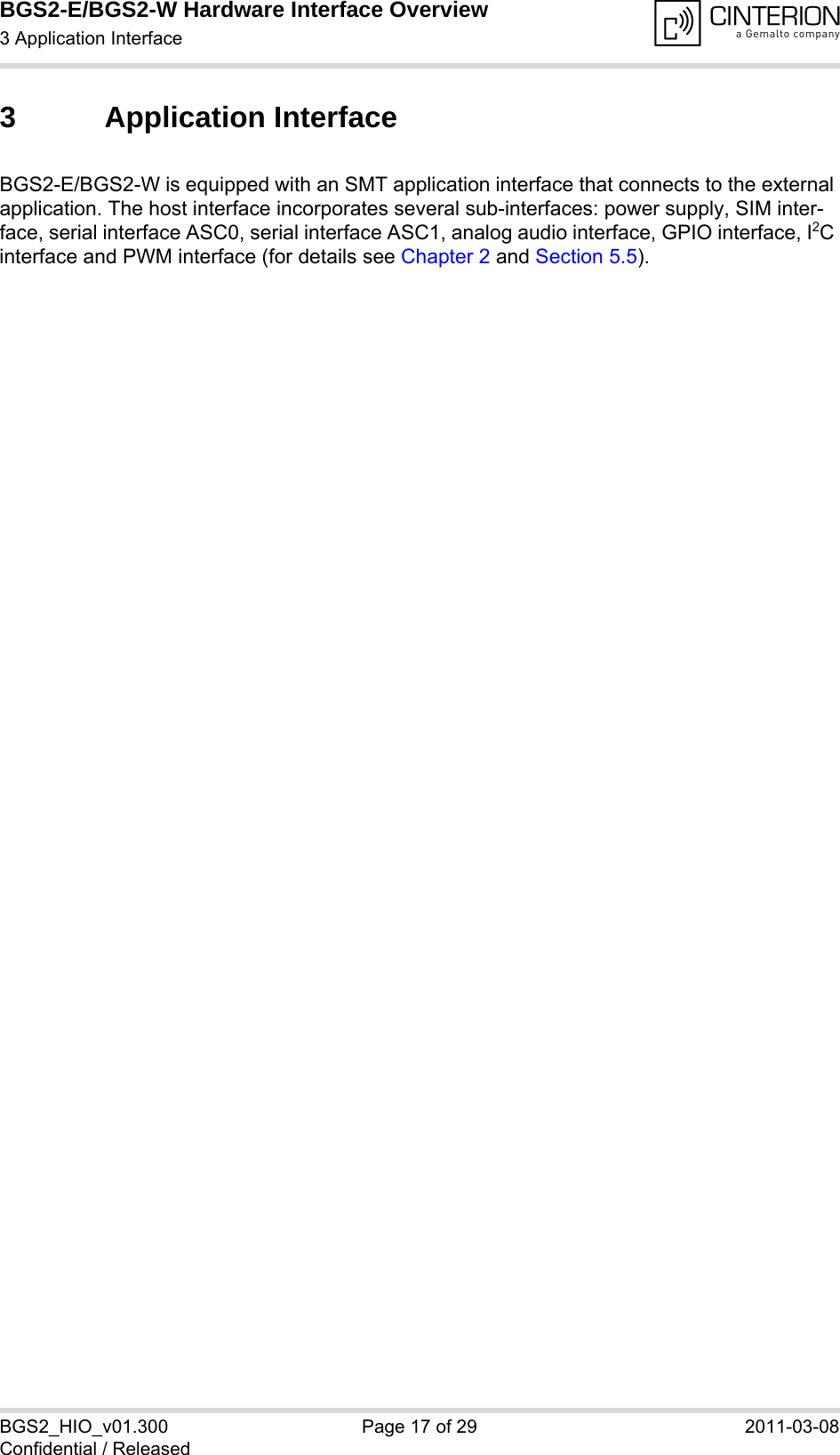
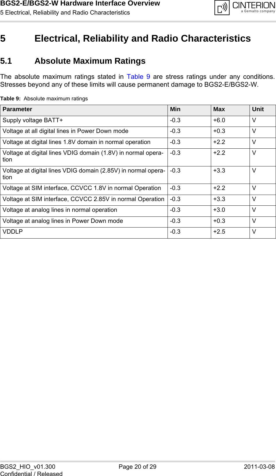
![BGS2-E/BGS2-W Hardware Interface Overview5.2 Operating Temperatures26BGS2_HIO_v01.300 Page 21 of 29 2011-03-08Confidential / Released5.2 Operating TemperaturesPlease note that the module’s lifetime, i.e., the MTTF (mean time to failure) may be reduced, ifoperated outside the restriced temperature range. A special URC reports whether the moduleenters or leaves the restriced temperature range (see [1]; AT^SCTM).Note that within the specified operating temperature ranges the board temperature may varyto a great extent depending on operating mode, used frequency band, radio output power andcurrent supply voltage. When data are transmitted over GPRS the quad band module variant automatically reverts toa lower Multislot Class if the temperature rises to the limit specified for normal operation and,vice versa, returns to the higher Multislot Class if the temperature is back to normal. Table 10: Board temperatureParameter Min Typ Max UnitNormal operation -30 +25 +85 °CRestricted operation -40 to -30 +85 to +90 °CAutomatic shutdown1Temperature measured on BGS2-E/BGS2-W board1. Due to temperature measurement uncertainty, a tolerance of ±3°C on the thresholds may occur.<-40 --- >+90 °CTable 11: Ambient temperature according to IEC 60068-2 (w/o forced air circulation)Parameter Min Typ Max UnitGSM Call @ max. RF-Power -40 +75 °CGPRS Class 8 @ max. RF-Power -40 +75 °CGPRS Class 10 @ max. RF-Power (quad band only) -40 +60 °CTable 12: Ambient temperature with forced air circulation (air speed 0.9m/s)Parameter Min Typ Max UnitGSM Call @ max. RF-Power -40 +80 °CGPRS Class 8 @ max. RF-Power -40 +80 °CGPRS Class 10 @ max. RF-Power (quad band only) -40 +70 °C](https://usermanual.wiki/THALES-DIS-AlS-Deutschland/BGS2/User-Guide-1427662-Page-21.png)