THALES DIS AlS Deutschland BGS5 GSM quadband module User Manual hid
Gemalto M2M GmbH GSM quadband module hid
UserManual.wiki
>
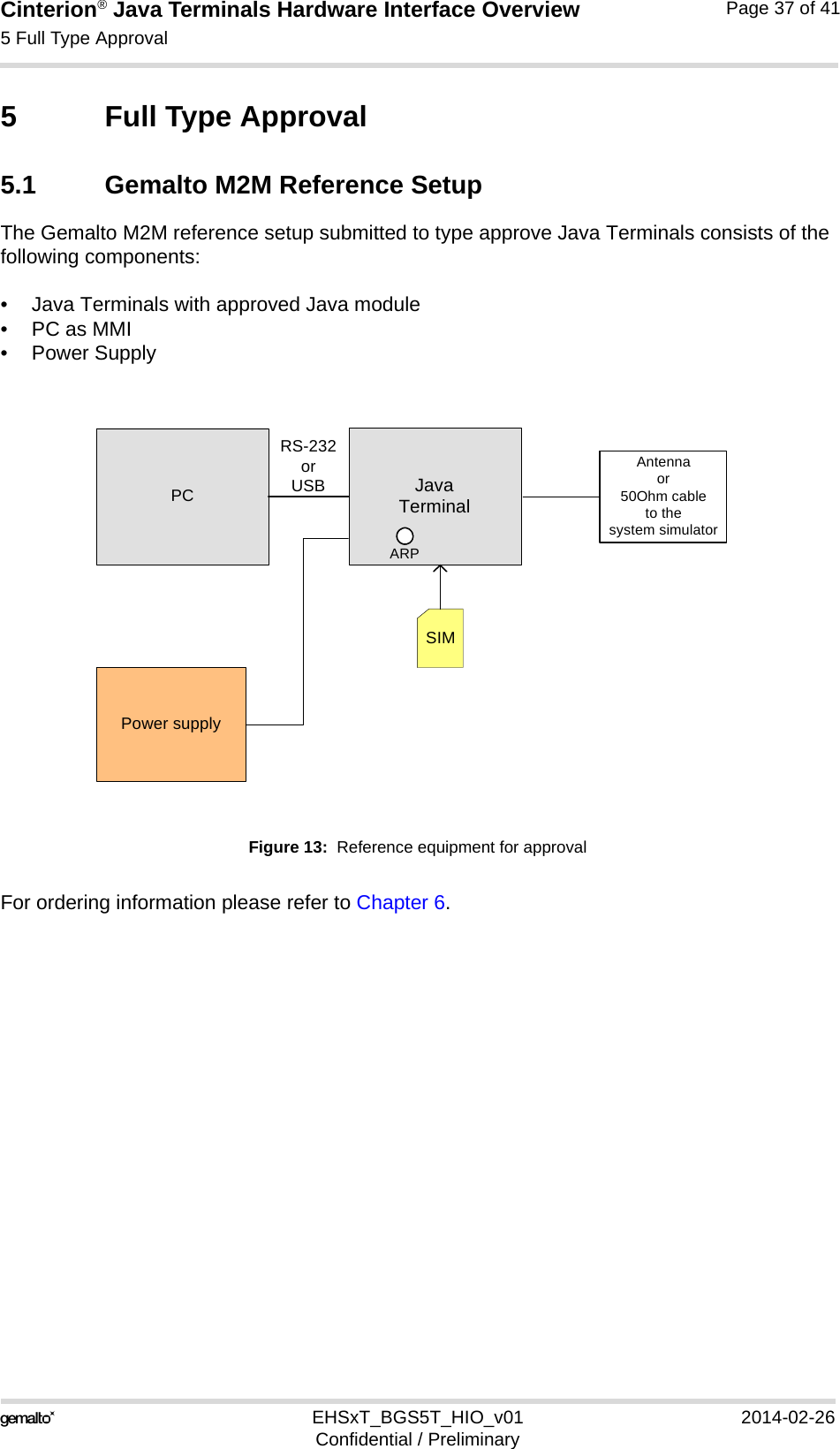
THALES DIS AlS Deutschland
>
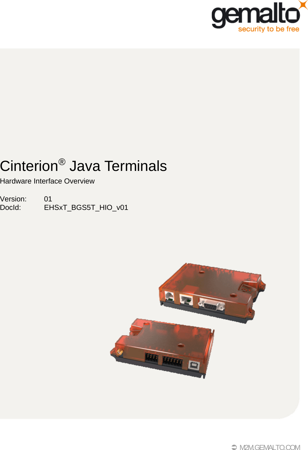
BGS5 User Manual
>
ehsxt_bgsxt_hio_um_V1
Contents
1.
_bgs5_hio_V1
2.
ehsxt_bgsxt_hio_um_V1
ehsxt_bgsxt_hio_um_V1
Navigation menu
Upload a User Manual
Namespaces
Wiki Guide
HTML
PDF
Info
Views
User Manual
Discussion / Help
Navigation
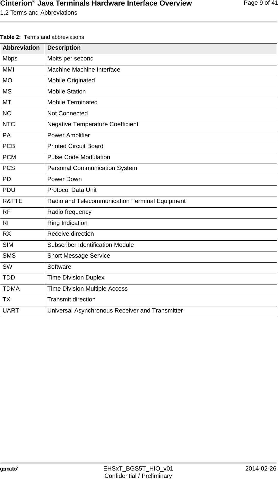
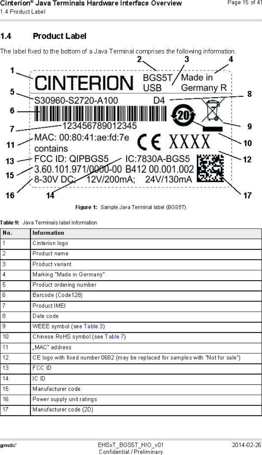
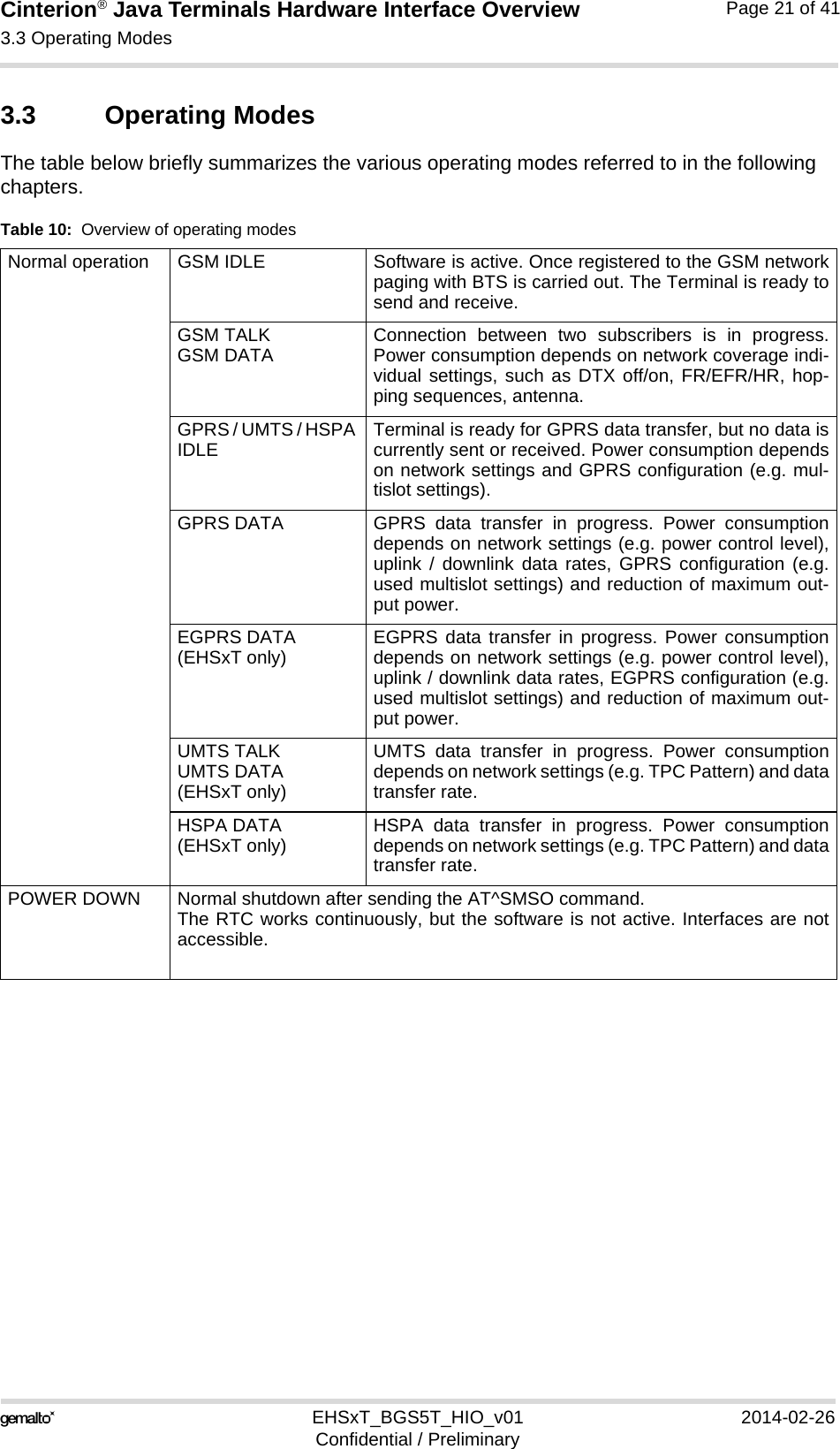
![Cinterion® Java Terminals Hardware Interface Overview1.1 Related Documents15EHSxT_BGS5T_HIO_v01 2014-02-26Confidential / PreliminaryPage 8 of 411.1 Related Documents[1] AT Command Set for your Java Terminal product[2] Release Notes for your Java Terminal productTo visit the Gemalto M2M GmbH Website please use the following link:http://m2m.gemalto.com1.2 Terms and AbbreviationsTable 2: Terms and abbreviationsAbbreviation DescriptionARP Antenna Reference PointATC AT CommandBTS Base Transceiver StationCB Cell BroadcastCODEC Coder-DecoderDCE Data Circuit terminating EquipmentDSR Data Set ReadyDTR Data Terminal ReadyEFR Enhanced Full RateEGSM Enhanced GSMEMC Electromagnetic CompatibilityESD Electrostatic DischargeETS European Telecommunication StandardFDMA Frequency Division Multiple AccessG.C.F. GSM Conformity ForumGSM Global Standard for Mobile CommunicationHW HardwareIC Integrated CircuitIF Intermediate Frequency IMEI International Mobile Equipment IdentifierI/O Input/ OutputIGT IgnitionISO International Standards OrganizationITU International Telecommunications Unionkbps kbits per secondLVD Low voltage Directive](https://usermanual.wiki/THALES-DIS-AlS-Deutschland/BGS5.ehsxt-bgsxt-hio-um-V1/User-Guide-2244117-Page-8.png)
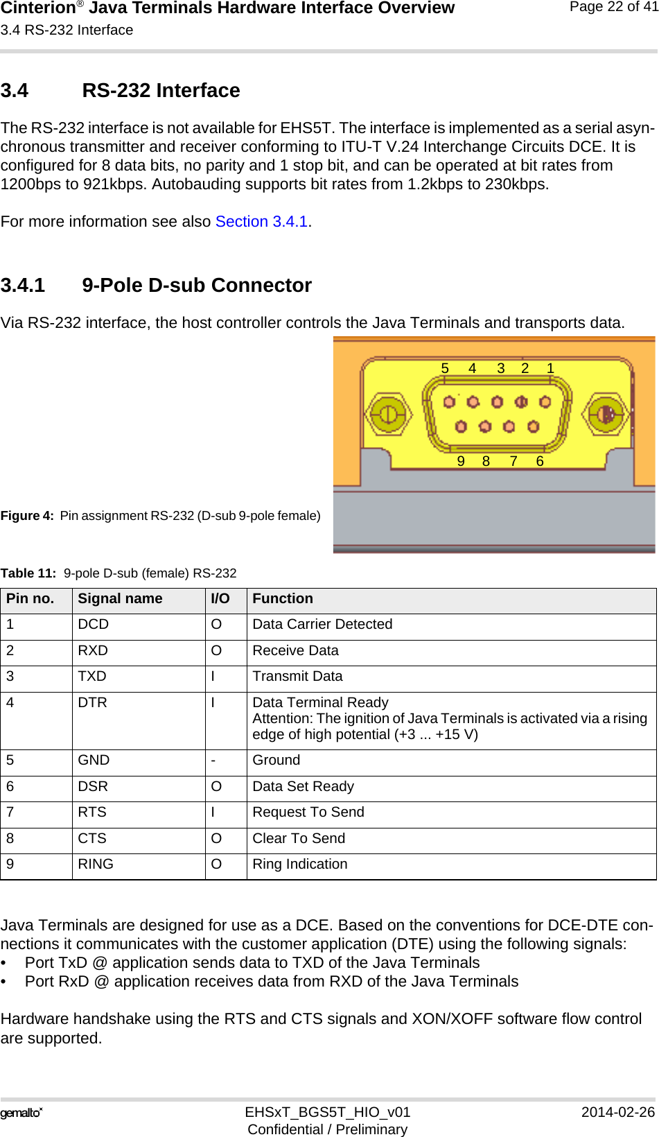
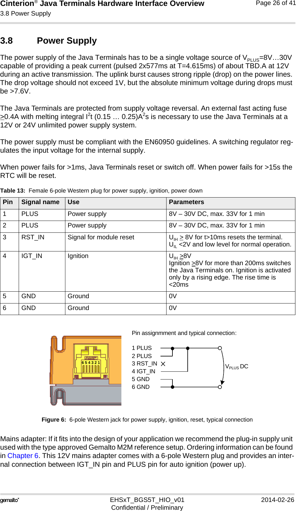
![Cinterion® Java Terminals Hardware Interface Overview3.8 Power Supply32EHSxT_BGS5T_HIO_v01 2014-02-26Confidential / PreliminaryPage 27 of 413.8.1 Turn Java Terminals onJava Terminals are turned on by plugging an appropriate power supply unit between PLUS and GND of the 6-pole Western jack. While the RST_IN pin (pin 3) is not active (voltage <2V) you can start the Java Terminals by activating the RS-232 DTR line if in POWER DOWN mode.The IGT_IN signal (pin 4) may be used to switch on Java Terminals if in POWER DOWN mode.After startup of the Java Terminals the RS-232 lines are in an undefined state for approx. 900ms. This may cause undefined characters to be transmitted over the RS-232 lines during this period.3.8.2 Reset Java TerminalsAn easy way to reset the Java Terminals is entering the command AT+CFUN=x,1. For details on AT+CFUN please see [1].As an alternative, you can shut down the Java Terminals as described in Section 3.8.3 and then restart it as described in Section 3.8.1.3.8.3 Turn Java Terminals offNormal shutdown:• To turn off the Java Terminals use the AT^SMSO command, rather than disconnecting themains adapter. This procedure lets the Java Terminals log off from the network and allows the software toenter a secure state and save data before disconnecting the power supply. After AT^SMSOhas been entered the Java Terminals returns the following result codes: ^SMSO: MS OFFOK^SHUTDOWNThe "^SHUTDOWN" result code indicates that the Java Terminals turns off in less than1 second. After the shutdown procedure is complete the Java Terminals enters thePOWER DOWN mode. The yellow LED stops flashing (see Section 3.12 for a detailed LEDdescription). The RTC is still fed from the voltage regulator in the power supply ASIC.Please note that if there is an auto ignition connection between PLUS and IGT_IN the mod-ule will restart automatically after a normal shutdown.](https://usermanual.wiki/THALES-DIS-AlS-Deutschland/BGS5.ehsxt-bgsxt-hio-um-V1/User-Guide-2244117-Page-27.png)
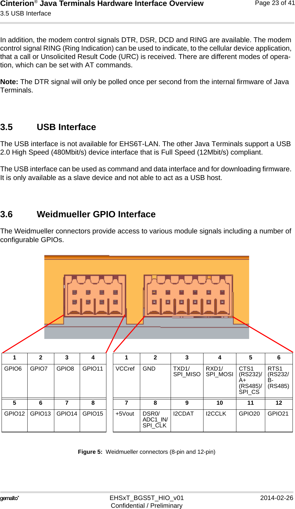
![Cinterion® Java Terminals Hardware Interface Overview3.9 Automatic thermal shutdown32EHSxT_BGS5T_HIO_v01 2014-02-26Confidential / PreliminaryPage 29 of 413.9 Automatic thermal shutdownAn on-board NTC measures the temperature of the built-in BGS2 module. If over- or undertem-perature is detected on the module the Java Terminals automatically shut down to avoid ther-mal damage to the system. Table 17 specifies the ambient temperature threshold for the Java Terminals. The automatic shutdown procedure is equivalent to the power-down initiated with the AT^SMSO command, i.e. Java Terminals log off from the network and the software enters a secure state avoiding loss of data. In IDLE mode it takes typically one minute to deregister from the network and to switch off. Alert messages transmitted before the Java Terminals switch off are implemented as Unsolic-ited Result codes (URCs). For details see the description of AT^SCTM command provided in [1]. Thermal shutdown will be deferred if a critical temperature limit is exceeded, while an emer-gency call or a call to a predefined phone number is in progress, or during a two minute guard period after power up. See [1] for details.3.10 RTCThe internal Real Time Clock (RTC) of the Java Terminals retain the time and date and handle the alarm (reminder) function. The AT+CCLK command serves to set the time and date, and AT+CALA specifies a reminder message. See [1] for details. A dedicated voltage regulator backs up the RTC even in POWER DOWN mode and enables Java Terminals to keep track of time and date. However, please note that the Alarm mode described in [1], Section AT+CALA, is not intended for the Java Terminals. The AT+CALA command can only be used to set a reminder message, but not to configure the mobile to wake up from POWER DOWN mode into Alarm mode. There-fore, after setting a timer with AT+CALA be sure not to shut down the Java Terminals by AT^SMSO or RST_IN signal.](https://usermanual.wiki/THALES-DIS-AlS-Deutschland/BGS5.ehsxt-bgsxt-hio-um-V1/User-Guide-2244117-Page-29.png)
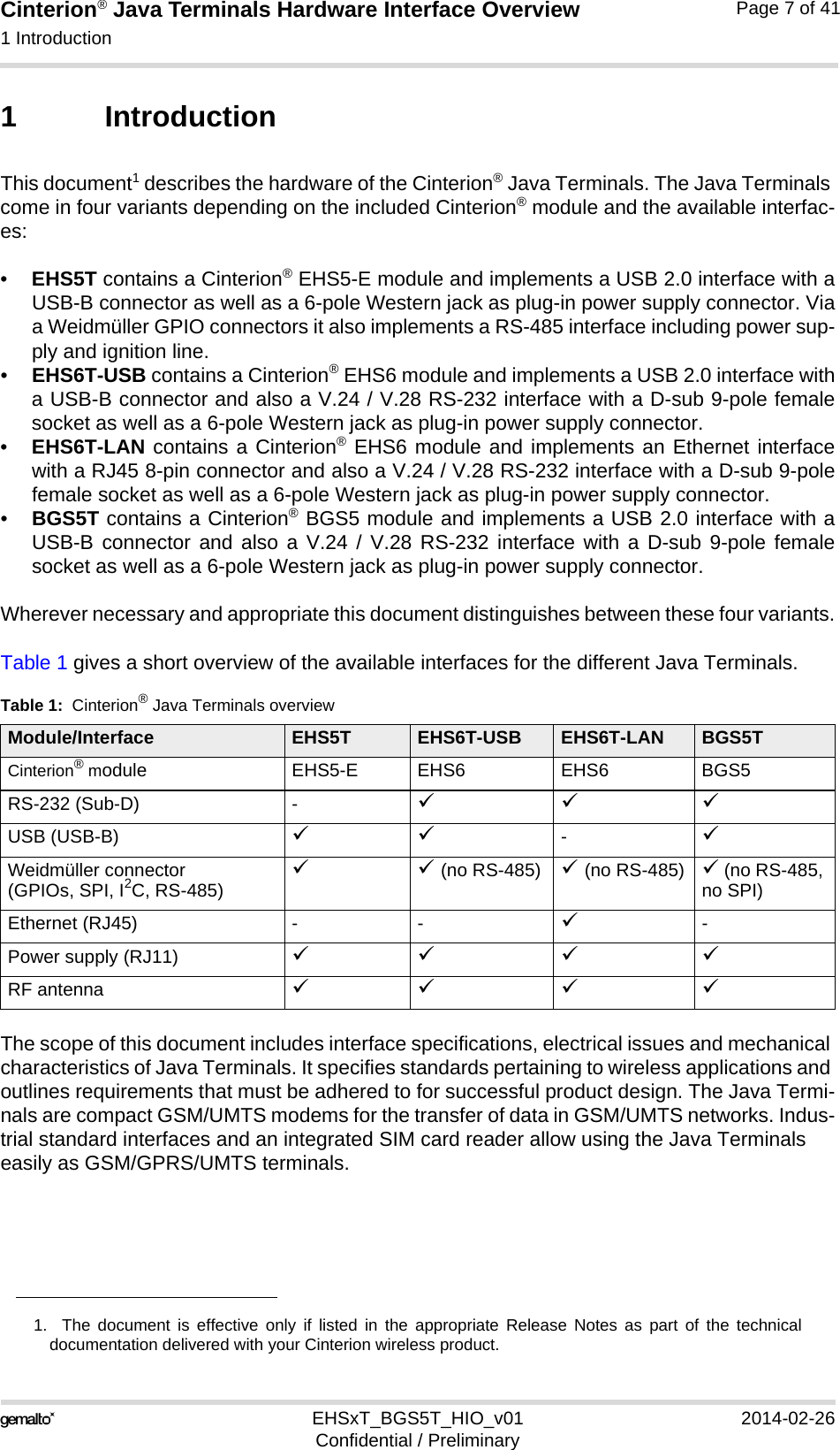
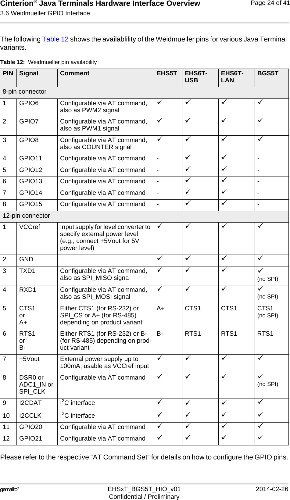
![Cinterion® Java Terminals Hardware Interface Overview3.12 Status LEDs32EHSxT_BGS5T_HIO_v01 2014-02-26Confidential / PreliminaryPage 31 of 413.12 Status LEDsJava Terminals have two LEDs indicating its operating states through the semitransparent cas-ing:• A green LED indicates whether the Java Terminals are ready to operate.• A yellow LED indicates the network registration state of the Java Terminals.Figure 8: Status LEDThe yellow LED is driven by a line of the integrated module that can be configured by using the AT^SLED command to either light permanently or to flash. For details on the AT command please refer to [1]. Green LED(Power on/off)Yellow LED(Network status)](https://usermanual.wiki/THALES-DIS-AlS-Deutschland/BGS5.ehsxt-bgsxt-hio-um-V1/User-Guide-2244117-Page-31.png)