THALES DIS AlS Deutschland EHS5T Gemalto EHS5 Terminal User Manual hid
Gemalto M2M GmbH Gemalto EHS5 Terminal hid
UserManual.wiki
>
THALES DIS AlS Deutschland
>
EHS5T User Manual
user manual
Navigation menu
Upload a User Manual
Namespaces
Wiki Guide
HTML
PDF
Info
Views
User Manual
Discussion / Help
Navigation
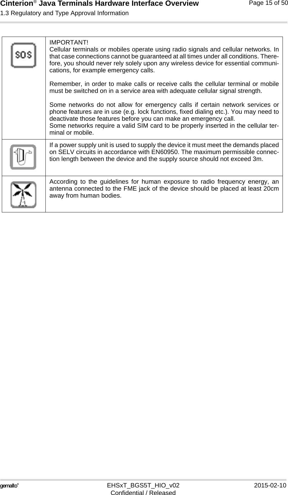
![Cinterion® Java Terminals Hardware Interface Overview1.1 Related Documents16EHSxT_BGS5T_HIO_v02 2015-02-10Confidential / ReleasedPage 9 of 501.1 Related Documents[1] AT Command Set for your Java Terminal product[2] Release Notes for your Java Terminal productTo visit the Gemalto M2M GmbH Website please use the following link:http://m2m.gemalto.com1.2 Terms and AbbreviationsTable 2: Terms and abbreviationsAbbreviation DescriptionARP Antenna Reference PointATC AT CommandBTS Base Transceiver StationCB Cell BroadcastCODEC Coder-DecoderDAI Digital Audio InterfaceDCE Data Circuit terminating EquipmentDSR Data Set ReadyDTR Data Terminal ReadyEFR Enhanced Full RateEGSM Enhanced GSMEMC Electromagnetic CompatibilityESD Electrostatic DischargeETS European Telecommunication StandardFDMA Frequency Division Multiple AccessG.C.F. GSM Conformity ForumGSM Global Standard for Mobile CommunicationHW HardwareIC Integrated CircuitIF Intermediate Frequency IMEI International Mobile Equipment IdentifierI/O Input/ OutputIGT IgnitionISO International Standards OrganizationITU International Telecommunications Unionkbps kbits per second](https://usermanual.wiki/THALES-DIS-AlS-Deutschland/EHS5T/User-Guide-2545270-Page-9.png)
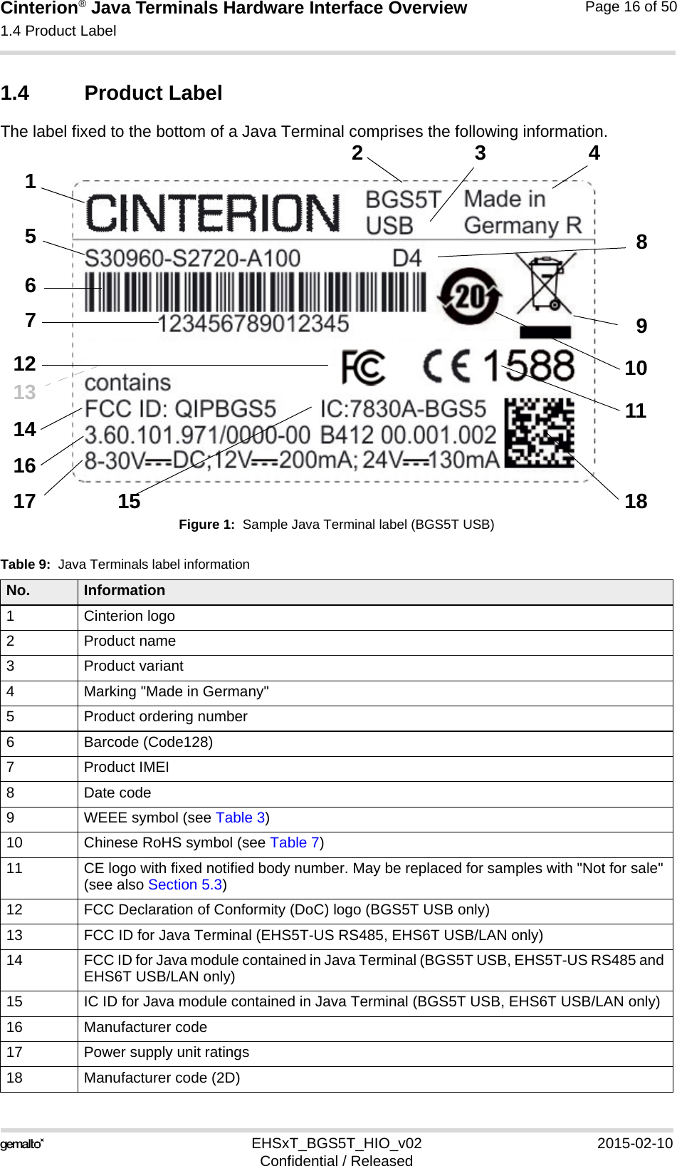
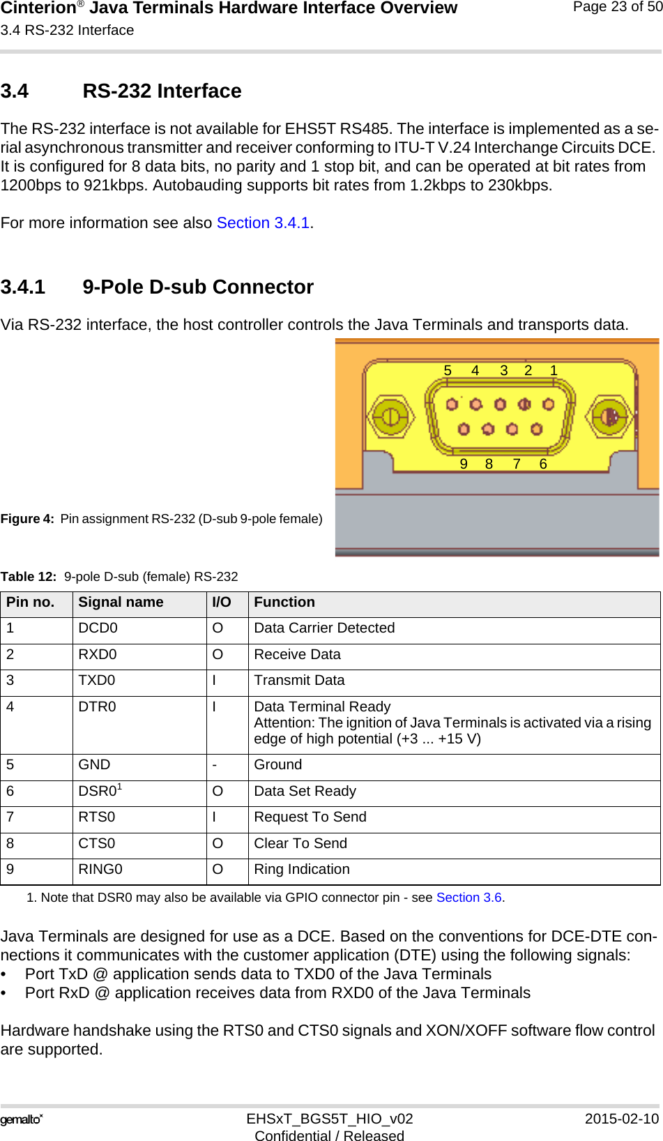
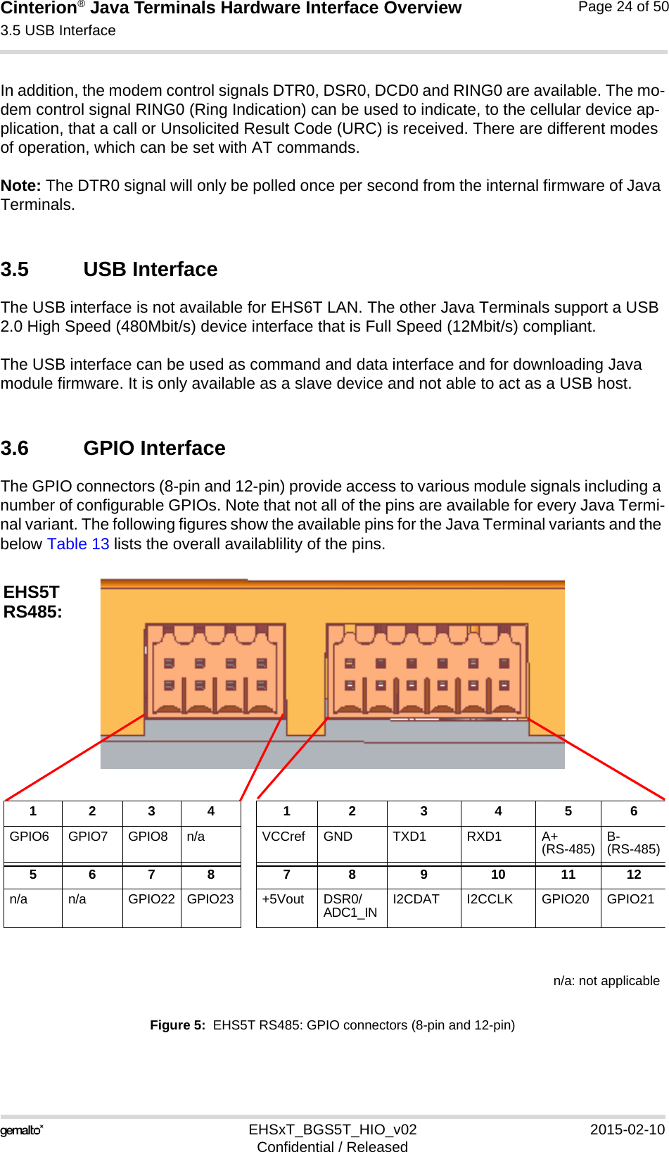
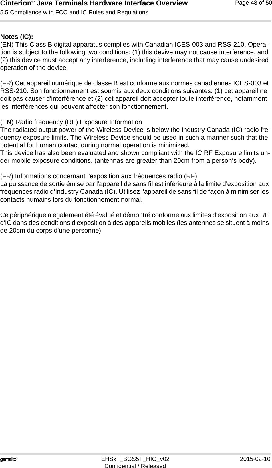
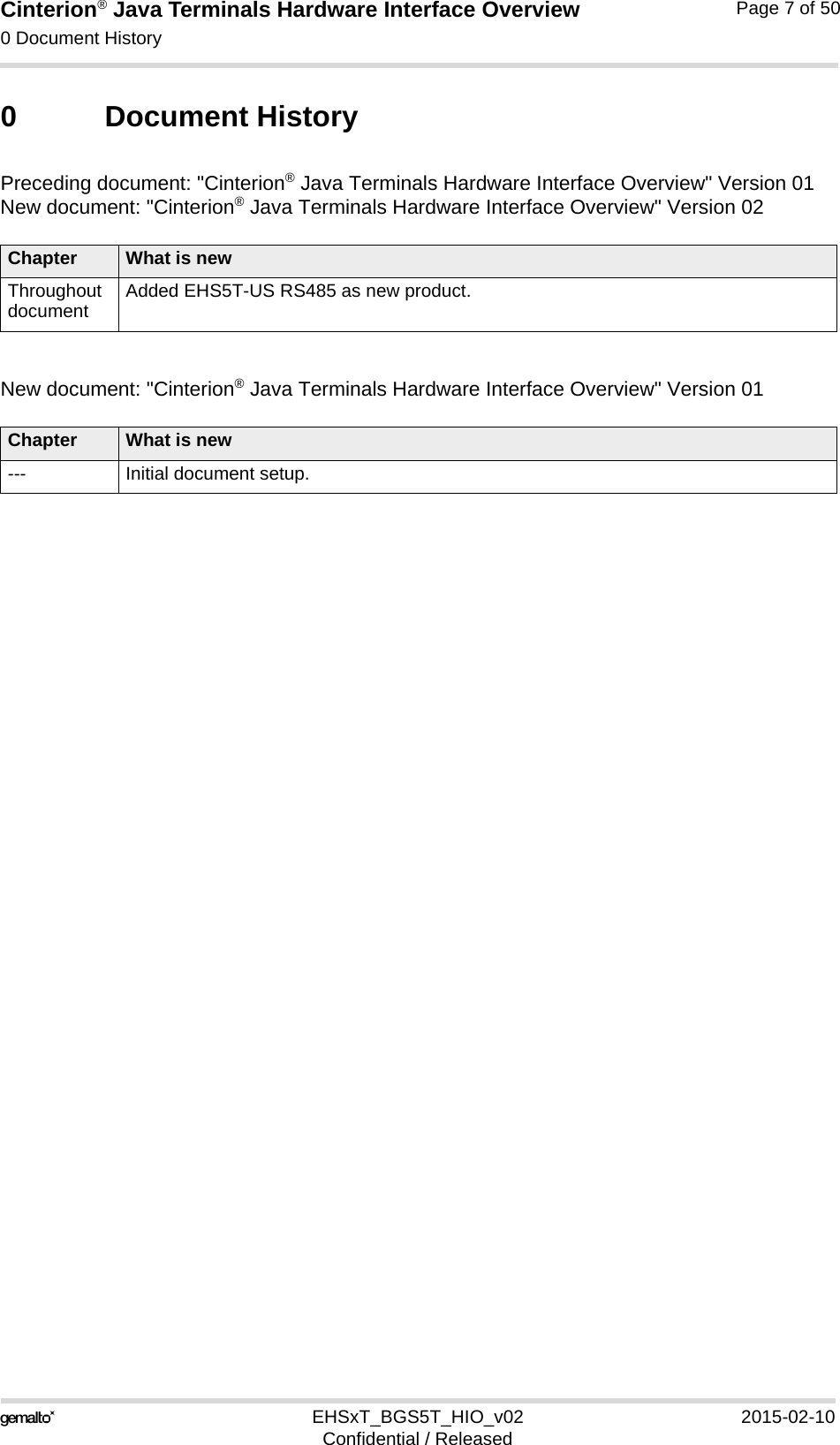
![Cinterion® Java Terminals Hardware Interface Overview3.6 GPIO Interface39EHSxT_BGS5T_HIO_v02 2015-02-10Confidential / ReleasedPage 27 of 50EHS5T‘s RS-485 interface is based on the TIA/EIA-485 standard defining electrical character-istics of drivers and receivers for use in balanced multidrop communication systems. RS-485 is used in a lot of different fieldbus systems like Profibus, Interbus, Modbus and P-net.RS-485 uses a shielded twisted pair cable where the inner pairs are used for balanced com-munication. The two conductors in each pair are called A and B. RS-485 is usually half-duplex.Data transmission speed depends on the length of the RS-485 bus cable and may be up to 115kbps.Note: If employing EHS5T‘s RS-485 interface be sure not to switch off the EHS5 module, e.g., by calling AT^SMSO, to put the module into Power Down mode. This completely occupies and therefore blocks the RS-485 bus, and may thus lead to a higher current consumption. Also, be sure not to activate SLEEP mode, e.g., by setting AT^SPOW with <mode>=2, for the EHS5 module, as the module may no longer be able to wake up from SLEEP mode, and will then have to be reset. 3.6.1 Serial Interface ASC1With EHS5T and EHS6T Java Terminals two respectively four pins at the GPIO connector can be configured as ASC1 interface signals to provide a 2- or 4-wire serial modem interface ASC1. The following pins at the GPIO connector can be configured as ASC1 interface signals: RXD1, TXD1, RTS1 and CTS1 (see also Table 13). The configuration is done by AT command AT^SCFG - see [1]. It is non-volatile and becomes active after a Java Terminal restart.Java Terminals are designed for use as a DCE. Based on the conventions for DCE-DTE con-nections they communicate with the customer application (DTE) using the following signals:• Port TXD @ application sends data to Java Terminal’s TXD1 signal line• Port RXD @ application receives data from the Java Terminal’s RXD1 signal lineHardware handshake using the RTS1 and CTS1 signals is only supported for EHS6T.](https://usermanual.wiki/THALES-DIS-AlS-Deutschland/EHS5T/User-Guide-2545270-Page-27.png)
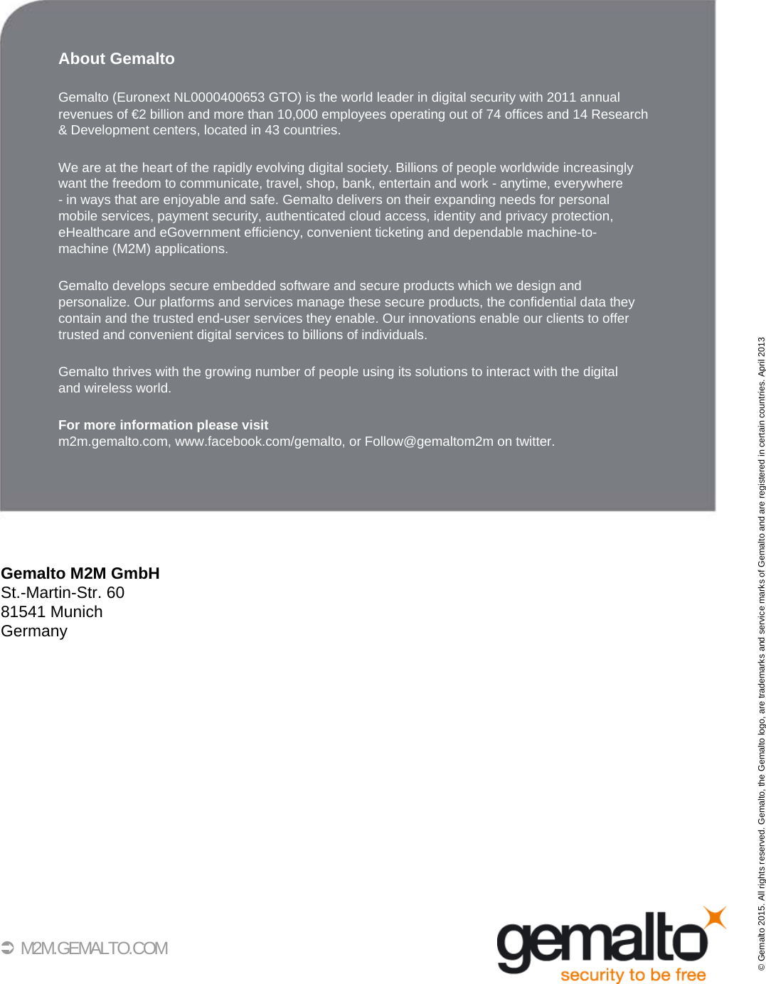
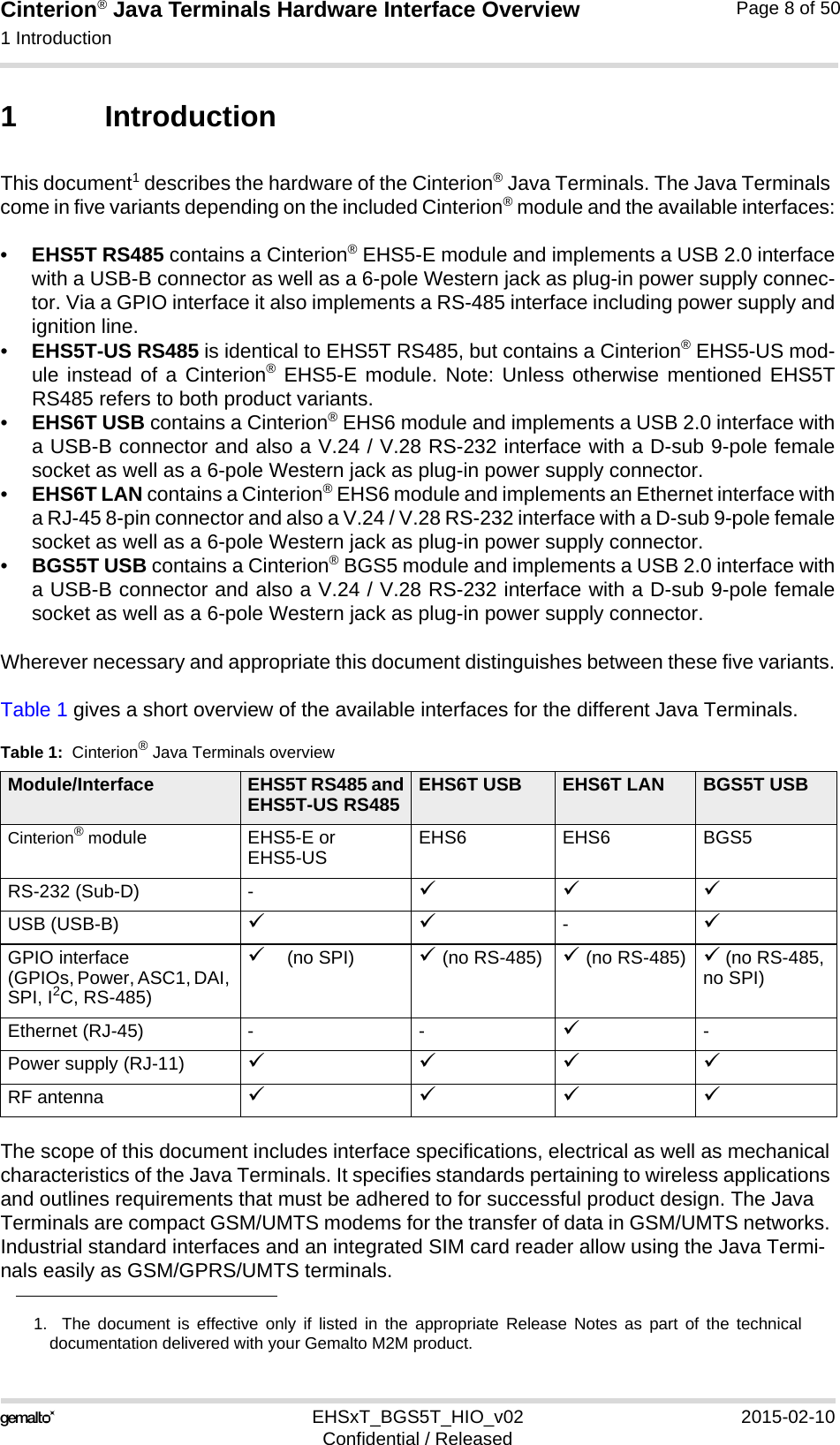
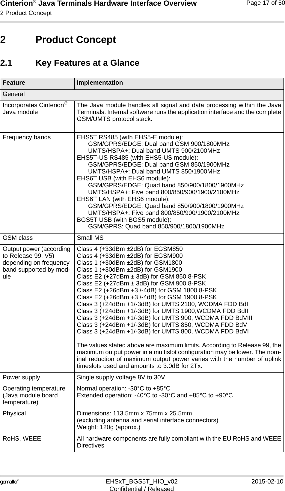
![Cinterion® Java Terminals Hardware Interface Overview3.6 GPIO Interface39EHSxT_BGS5T_HIO_v02 2015-02-10Confidential / ReleasedPage 28 of 503.6.2 Digital Audio Interface Four pins at the Java Terminals‘ GPIO connector can be configured as digital audio interface(DAI). The DAI can be used to connect audio devices capable of pulse code modulation (PCM).The PCM functionality allows for the use of an external codec like the W681360. The DAI interface supports a 256kHz, long frame synchronization master mode with the follow-ing features:• 16 Bit linear• 8kHz sample rate / 125µs frame duration• The most significant bit MSB is transferred first• Data write at rising edge / data read at falling edge• Common frame sync signal for transmit and receiveThe following pins at the GPIO connector can be configured as DAI/PCM interface signals: TX-DDAI, RXDDAI, TFSDAI and SCLK (see also Table 13). The configuration is done byAT^SCFG command - see [1]. It is non-volatile and becomes active after a module restart. DAI/PCM and GPIO functionalities for these lines are mutually exclusive. Table 14 describes theavailable DAI/PCM lines at the digital audio interface1. Figure 8 shows the PCM timing for the master mode available with Java Terminals.Figure 8: Long frame PCM timing, 256kHz1. Note: For the DAI interface to operate, the directions of the Java Terminals‘ GPIO level shifters mustbe set according to the defined directions of the DAI signals. Table 14: Overview of DAI/PCM signalsSignal name Input/Output DescriptionTXDDAI (GPIO20) O PCM data from Java Terminals to external codec.RXDDAI (GPIO21) I PCM data from external codec to Java Terminals.TFSDAI (GPIO22) O Frame synchronization signal to external codec:Long frame (8kHz)SCLK (GPIO23) O Bit clock to external codec: 256kHz SCLK TXDDAI RXDDAI TFSDAI MSB MSB LSB LSB 14 13 14 13 1 1 12 12 2 2 MSB MSB 125 µs](https://usermanual.wiki/THALES-DIS-AlS-Deutschland/EHS5T/User-Guide-2545270-Page-28.png)
![Cinterion® Java Terminals Hardware Interface Overview3.6 GPIO Interface39EHSxT_BGS5T_HIO_v02 2015-02-10Confidential / ReleasedPage 29 of 503.6.3 I2C InterfaceTwo lines of the Java Terminals‘ GPIO connector are I2C lines. I2C is a serial, 8-bit orienteddata transfer bus for bit rates up to 400kbps in Fast mode. It consists of two lines, the serialdata line I2CDAT and the serial clock line I2CCLK. The Java Terminals‘ internal Java moduleact as a single master device, e.g. the clock I2CCLK is driven by the Java module. I2CDAT isa bi-directional line. Each device connected to the bus is software addressable by a unique 7-bit address, and simple master/slave relationships exist at all times. The Java module operatesas master-transmitter or as master-receiver. An external application transmits or receives dataonly on request of the module.To configure and activate the I2C bus use the AT^SSPI command. Detailed information on theAT^SSPI command as well explanations on the protocol and syntax required for data transmis-sion can be found in [1].With the external application, I2CDAT and I2CCLK lines need to be connected to a positivesupply voltage via a pull-up resistor. Note: Good care should be taken when connecting the I2C lines to the external application: Thewires of I2CCLK and I2CDAT should be equal in length and as short as possible.11](https://usermanual.wiki/THALES-DIS-AlS-Deutschland/EHS5T/User-Guide-2545270-Page-29.png)
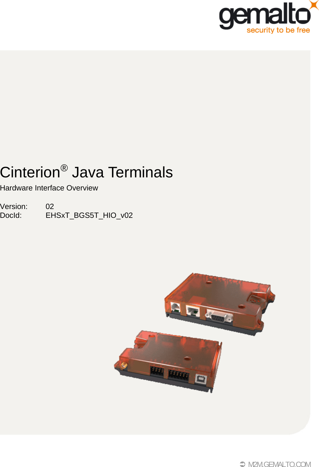
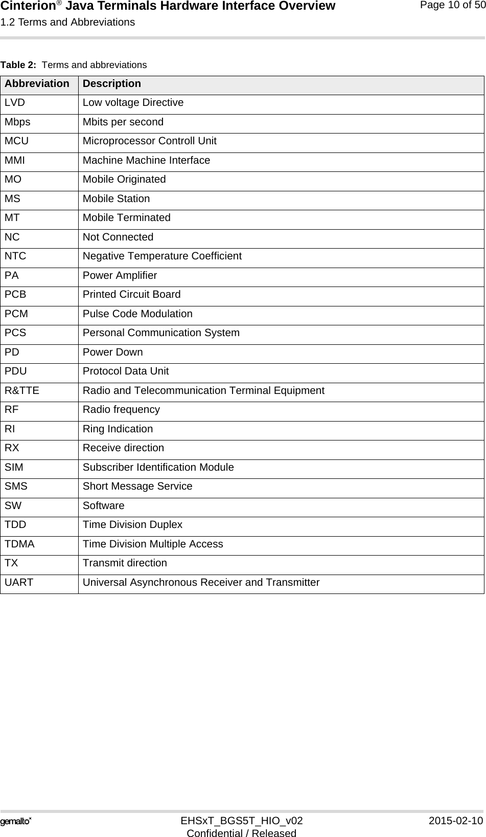
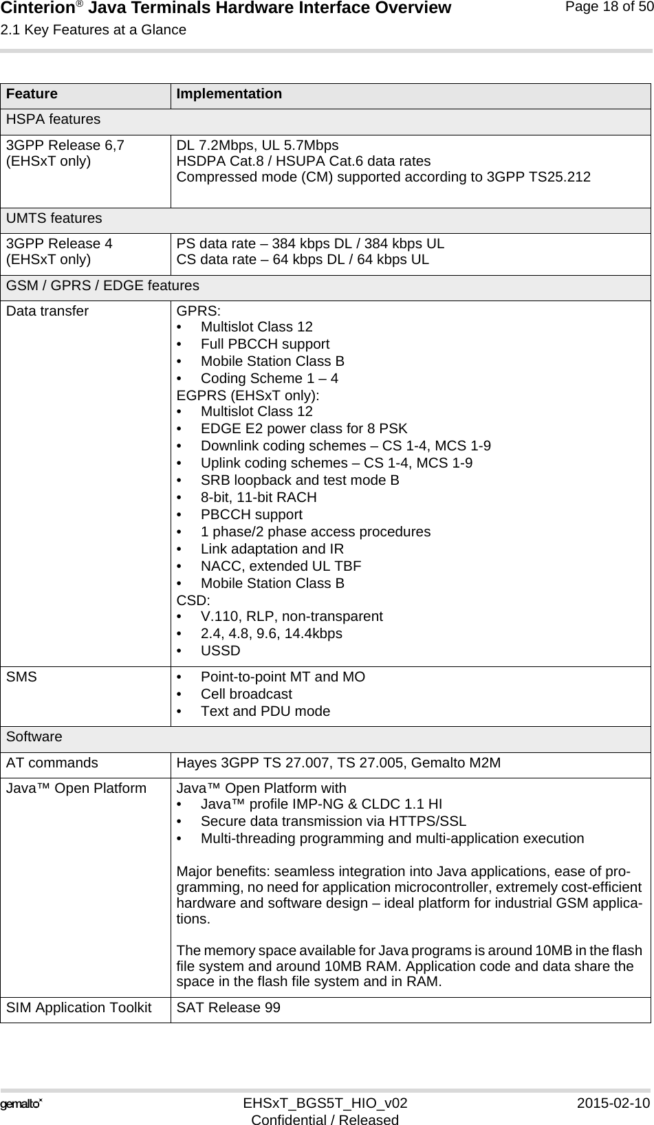
![Cinterion® Java Terminals Hardware Interface Overview3.6 GPIO Interface39EHSxT_BGS5T_HIO_v02 2015-02-10Confidential / ReleasedPage 30 of 503.6.4 SPI Interface For EHS6T Java Terminals four GPIO interface pins can be configured as Serial Peripheral In-terface (SPI). The SPI is a synchronous serial interface for control and data transfer betweenJava Terminals and the external application. Only one application can be connected to the SPIand the interface supports only master mode. The transmission rates are up to 6.5Mbit/s. TheSPI interface comprises the two data lines MOSI and MISO, the clock line SPI_CLK a well asthe chip select line SPI_CS.The following pins at the GPIO connector can be configured as SPI interface signals: SPI_CLK, SPI_MOSI, SPI_MISO and SPI_CS (see also Table 13). The configuration is done by AT com-mand (see [1]). It is non-volatile and becomes active after a module restart. To configure and activate the SPI interface use the AT^SSPI command. Detailed informationon the AT^SSPI command as well explanations on the SPI modes required for data transmis-sion can be found in [1]. SPI, ADC1_IN and DSR0 functionalities are mutually exclusive.In general, SPI supports four operation modes. The modes are different in clock phase andclock polarity. The module’s SPI mode can be configured by using the AT command AT^SSPI.Make sure the module and the connected slave device works with the same SPI mode.Figure 9 shows the characteristics of the four SPI modes. The SPI modes 0 and 3 are the mostcommon used modes. Figure 9: Characteristics of SPI modesSPI MODE 0 SPI MODE 1SPI MODE 2 SPI MODE 3Clock phaseClock polaritySPI_CSMOSISPI_CLKMISOSPI_CSMOSISPI_CLKMISOSPI_CSMOSISPI_CLKMISOSPI_CSMOSISPI_CLKMISOSample SampleSample Sample](https://usermanual.wiki/THALES-DIS-AlS-Deutschland/EHS5T/User-Guide-2545270-Page-30.png)
![Cinterion® Java Terminals Hardware Interface Overview3.6 GPIO Interface39EHSxT_BGS5T_HIO_v02 2015-02-10Confidential / ReleasedPage 31 of 503.6.5 PWM Interface The GPIO6 and GPIO7 pins at the GPIO connector can be configured as Pulse Width Modu-lation signals PWM1 and PWM2 by AT^SCFG command - see [1]. The PWM interface linesare output lines and can be used, for example, to connect buzzers. The PWM1 line is sharedwith GPIO7 and the PWM2 line is shared with GPIO6 (see also Table 13). GPIO and PWMfunctionalities are mutually exclusive1.3.6.6 Pulse Counter The GPIO8 pin at the GPIO connector can be configured as pulse counter line COUNTER byAT^SCFG command - see [1]. The pulse counter interface is an input line and can be used, forexample, as a clock (see also Table 13). GPIO and COUNTER functionalities are mutuallyexclusive1. 3.6.7 Analog-to-Digital Converter (ADC)ADC1_IN can be used for general purpose voltage measurements. ADC1_IN is configured and read by the AT^SRADC command - see [1]. ADC1_IN, DSR0 and SPI functionalities are mu-tually exclusive.3.6.8 DSR0 signalThe DSR0 line available at the RS-232 interface is also routed to the GPIO connector and avail-able as a separate pin. DSR0 can be configured by AT^SCFG command - see [1]. DSR0, ADC1_IN and SPI functionalities are mutually exclusive.1. Note: For the PWM interface and pulse counter to operate, the directions of the Java Terminals‘ GPIOlevel shifters must be set according to the defined directions of the PWM and COUNTER signals.](https://usermanual.wiki/THALES-DIS-AlS-Deutschland/EHS5T/User-Guide-2545270-Page-31.png)
![Cinterion® Java Terminals Hardware Interface Overview3.9 Power Up/Power Down Scenarios39EHSxT_BGS5T_HIO_v02 2015-02-10Confidential / ReleasedPage 34 of 503.9 Power Up/Power Down ScenariosIn general, be sure not to turn on the Java Terminals while it is beyond the safety limits of volt-age and temperature. Java Terminals immediately switch off after having started and detected these inappropriate conditions. In extreme cases this can cause permanent damage to the Java Terminals.3.9.1 Turn Java Terminals onThere are various possibilities to turn on Java Terminals and start into normal mode, depending on connecting and/or operating states. If powered off (i.e., if Java Terminals‘ power supply is disconnected):• Java Terminals can simply be started up by plugging an appropriate power supply unitbetween PLUS and GND of the 6-pole Western jack.If switched off (i.e., while in Power Down mode):• Java Terminals can be started up by activating the IGT_IN signal (pin 4). • Java Terminals can be started up by activating the RS-232 DTR line (as long as RST_INsignal (pin 3) is not active (voltage <2V)• Java Terminals can be started up by configuring the watchdog appropriately. Note: With an “auto-ignition“ connection between IGT_IN and PLUS (see Section 3.8) Java Terminals will automatically restart into normal mode after switch off (see Section 3.9.3). The start up variant from Power Down mode is therefore only applicable if there is no such “auto-ignition“ connection at the power supply unit. 3.9.2 Reset/Restart Java TerminalsThere are various possibilities to reset/restart Java Terminals:• Java Terminals can be reset/restarted by entering the command AT+CFUN=x,1. For detailson AT+CFUN please see [1].• Java Terminals can be reset/restarted by configuring the watchdog appropriately. • Java Terminals can be reset/restarted by configuring a wake-up alarm (see Section 3.12)before using AT^SMSO to turn them off and send them into Power Down mode.• Java Terminals can be reset/restarted by simply shutting them down as described in Sec-tion 3.9.3 and then restarting them as described in Section 3.9.1. Note: With an “auto igni-tion“ connection between IGT_IN and PLUS (see Section 3.8) it is ensured that the modulewill automatically restart after a normal shutdown using AT^SMSO.](https://usermanual.wiki/THALES-DIS-AlS-Deutschland/EHS5T/User-Guide-2545270-Page-34.png)
![Cinterion® Java Terminals Hardware Interface Overview3.10 Automatic thermal shutdown39EHSxT_BGS5T_HIO_v02 2015-02-10Confidential / ReleasedPage 36 of 503.10 Automatic thermal shutdownAn on-board NTC measures the temperature of the built-in Java module. If over- or undertem-perature is detected on the module the Java Terminals automatically shut down to avoid ther-mal damage to the system. The automatic shutdown procedure is equivalent to the power-down initiated with the AT^SMSO command, i.e. Java Terminals log off from the network and the software enters a secure state avoiding loss of data.Alert messages transmitted before the Java Terminals switch off are implemented as Unsolic-ited Result codes (URCs). For details see the description of AT^SCTM command provided in [1]. The watchdog can be configured to restart the Java Terminals after a defined period of time.3.11 Hardware WatchdogThe Java Terminals feature a programmable hardware watchdog that permanently monitors the terminals‘ hardware and can be configured to react to various hardware states. The watch-dog may for example be configured to periodically restart the terminal, independant of its cur-rent operating state. 3.12 RTCThe internal Real Time Clock (RTC) of the Java Terminals retains the time and date and han-dles the alarm function. The AT+CCLK command serves to set the time and date, and AT+CA-LA specifies a reminder message or sets an alarm for the .Java Terminals to wake up. See [1] for details. A dedicated voltage regulator backs up the RTC even in Power Down mode and enables Java Terminals to keep track of time and date. However, please note that the Alarm function described in [1], Section AT+CALA, will only work if there is no “auto ignition“ connection active between IGT_IN pin and PLUS pin at the power supply unit that will automatically trigger a restart (see Section 3.8). Otherwise, the AT+CALA command can only be used to set a reminder message, but not to configure the Java Terminals to wake up from Power Down mode.](https://usermanual.wiki/THALES-DIS-AlS-Deutschland/EHS5T/User-Guide-2545270-Page-36.png)
![Cinterion® Java Terminals Hardware Interface Overview3.14 Status LEDs39EHSxT_BGS5T_HIO_v02 2015-02-10Confidential / ReleasedPage 38 of 503.14 Status LEDsJava Terminals have two LEDs indicating its operating states through the semitransparent cas-ing:• A green LED indicates whether the Java Terminals are ready to operate and reports certainwatchdog operations.• A yellow LED indicates the network registration state of the Java Terminals.Figure 13: Status LEDThe yellow LED can be configured by using the AT^SLED command to either light permanently or to flash. For details on the AT command please refer to [1]. Green LED(Power on/off)Yellow LED(Network status)](https://usermanual.wiki/THALES-DIS-AlS-Deutschland/EHS5T/User-Guide-2545270-Page-38.png)