THALES DIS AlS Deutschland EHS6T Gemalto EHS6 Terminal User Manual hid
Gemalto M2M GmbH Gemalto EHS6 Terminal hid
UserManual.wiki
>
THALES DIS AlS Deutschland
>
EHS6T User Manual
>
User Manual
Contents
1.
User Manual
2.
user manual
User Manual
Navigation menu
Upload a User Manual
Namespaces
Wiki Guide
HTML
PDF
Info
Views
User Manual
Discussion / Help
Navigation
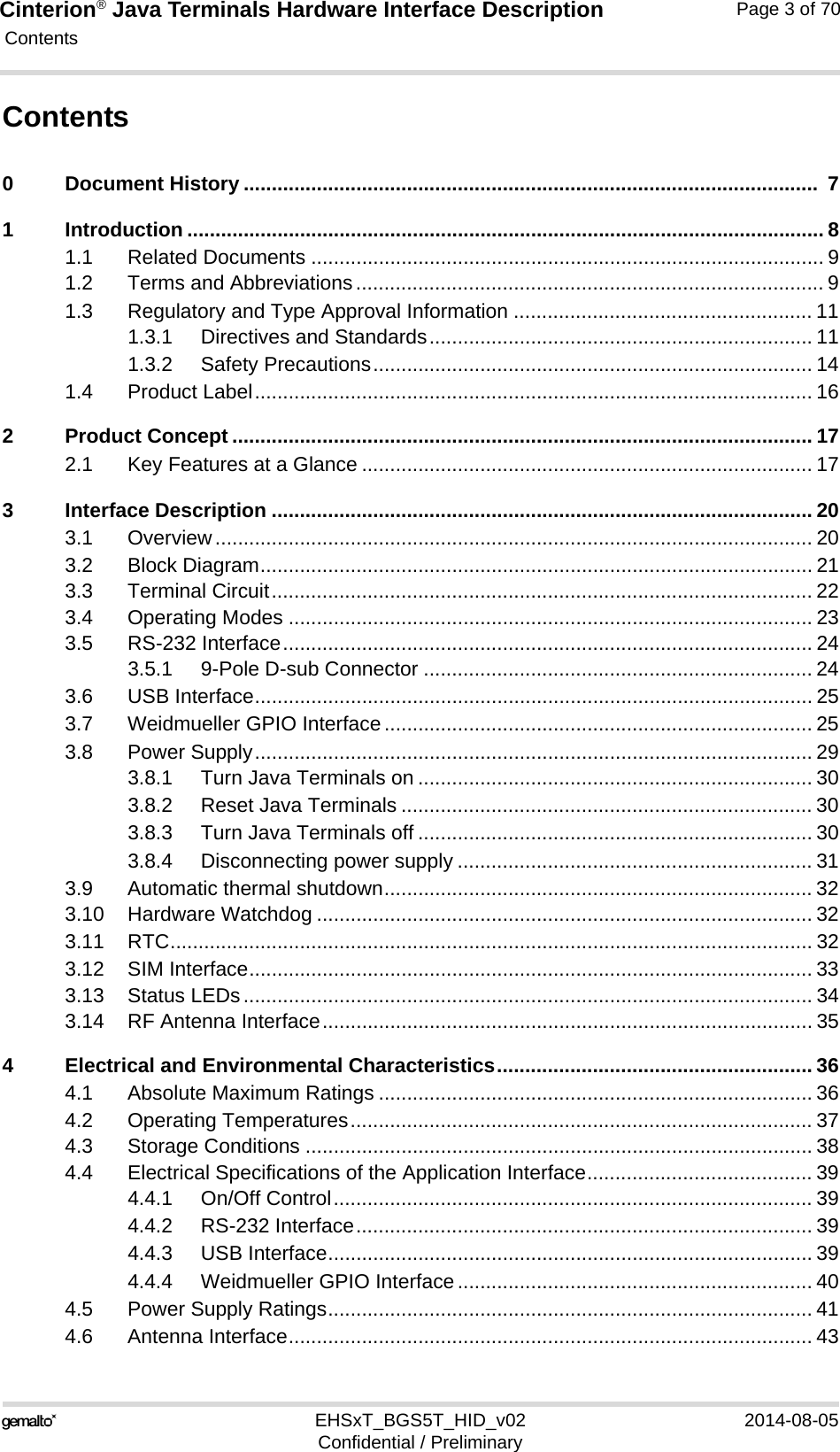
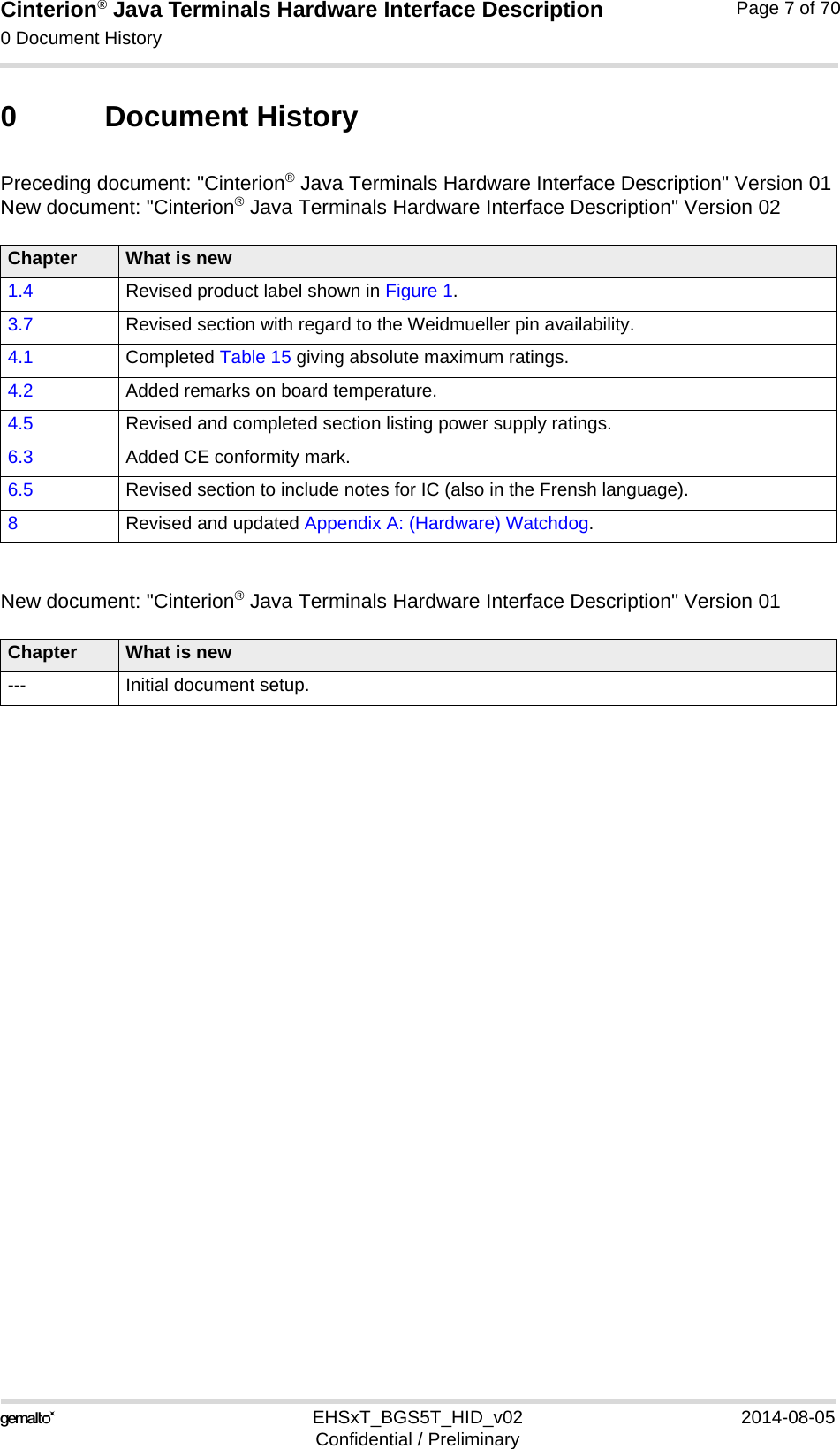
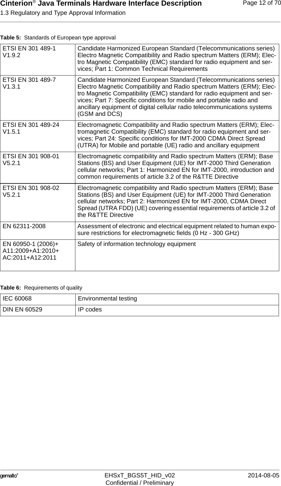
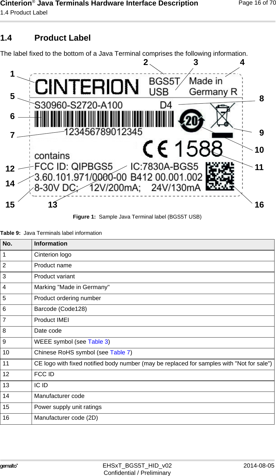
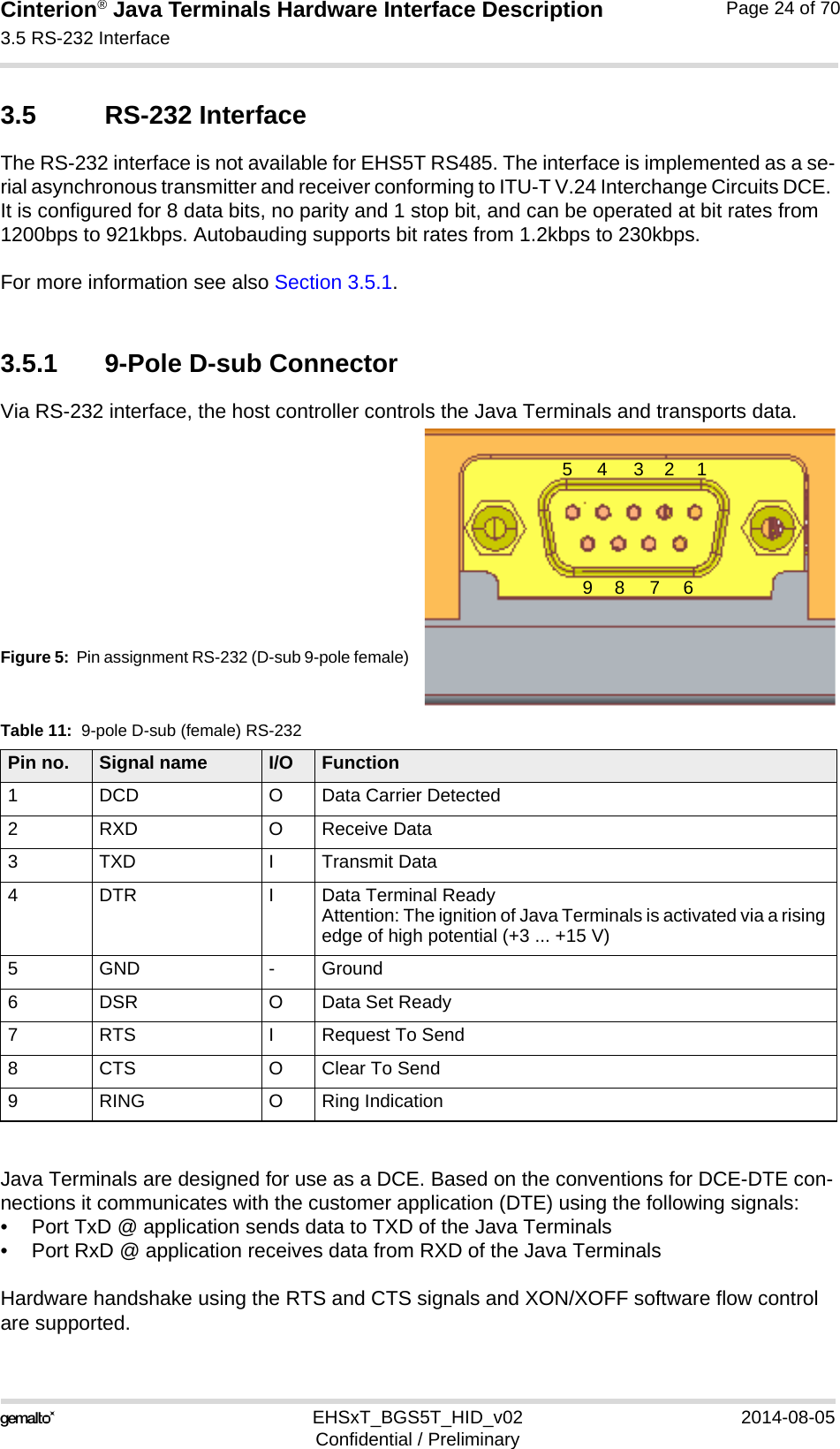
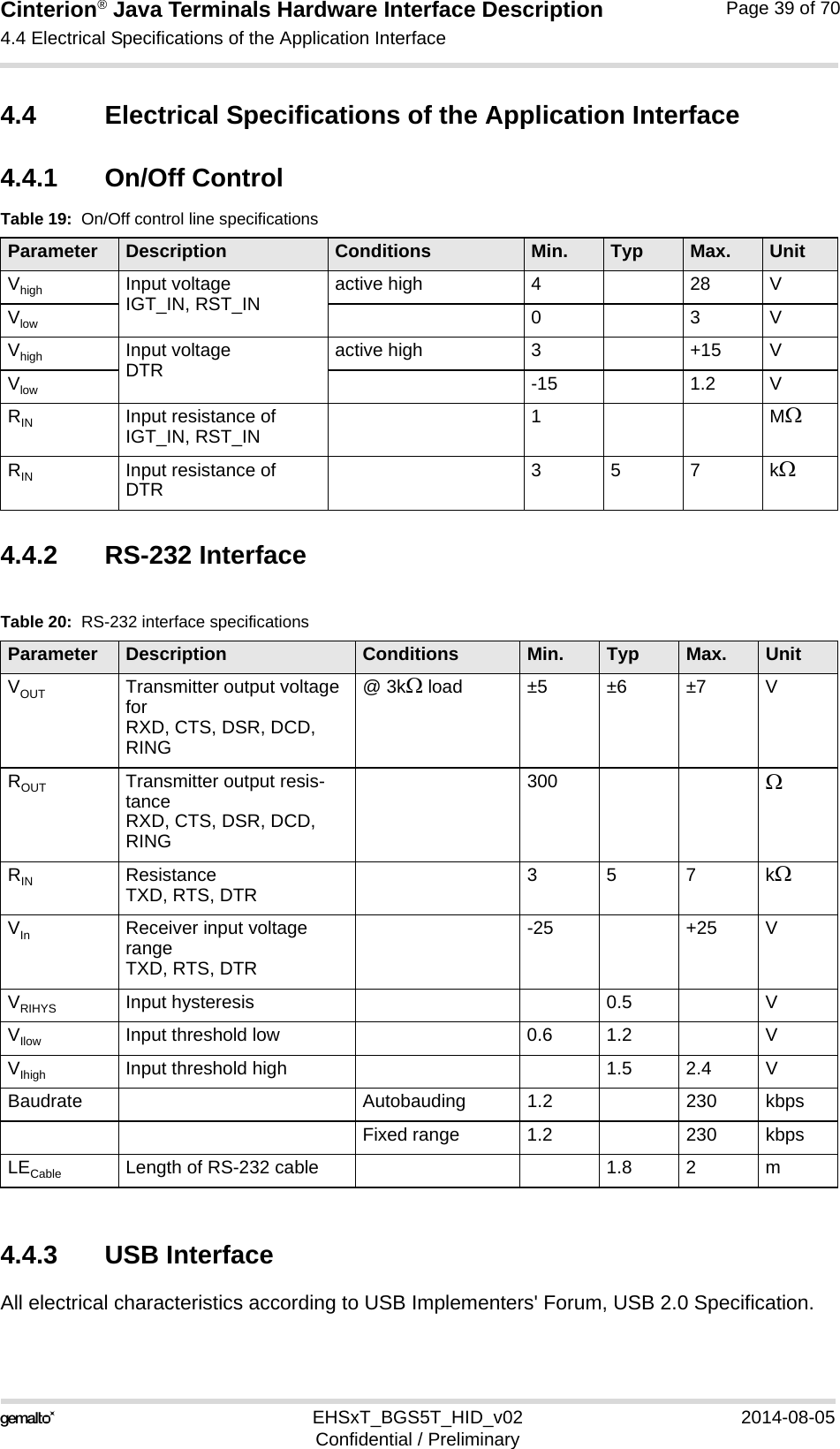
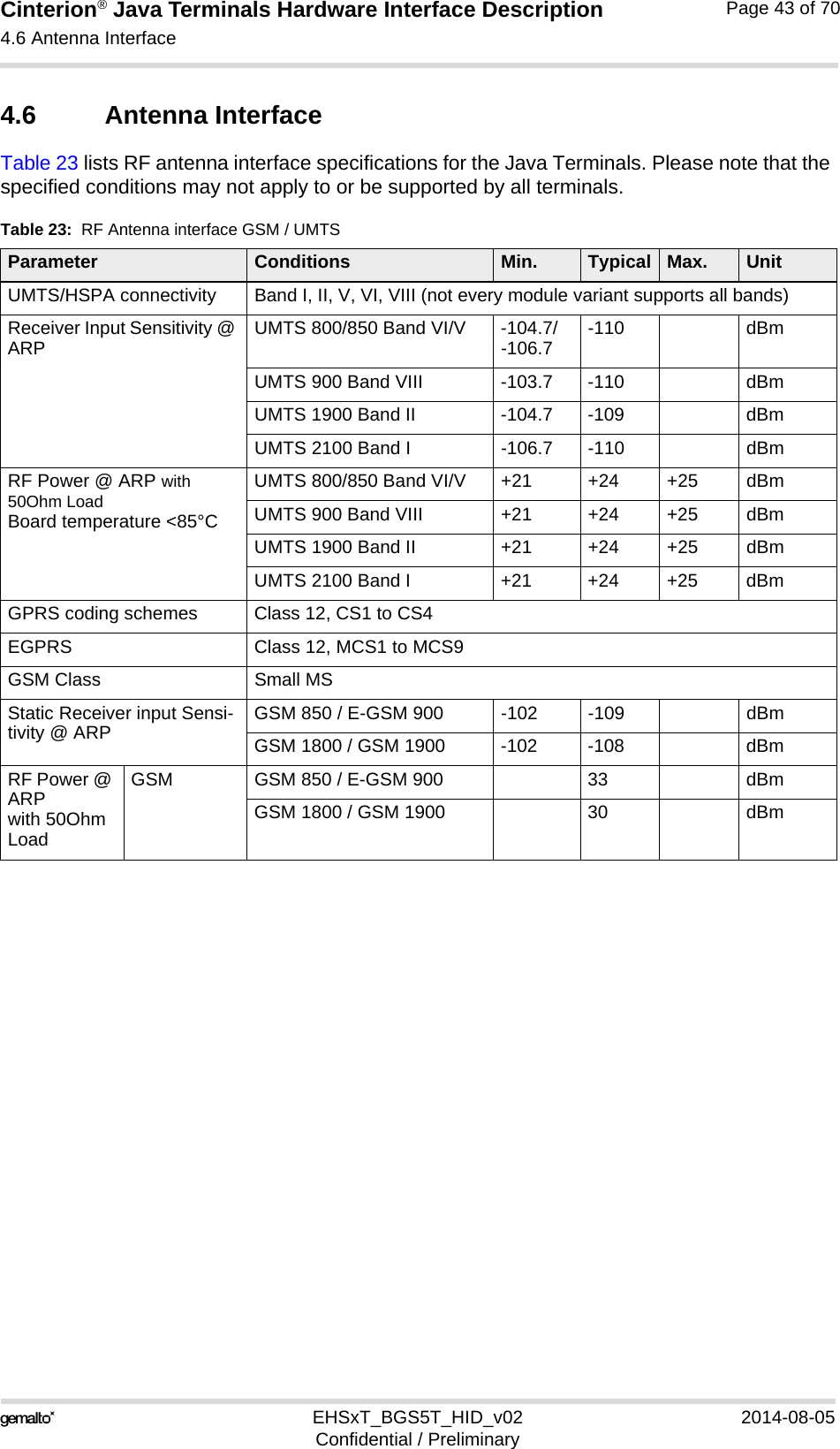
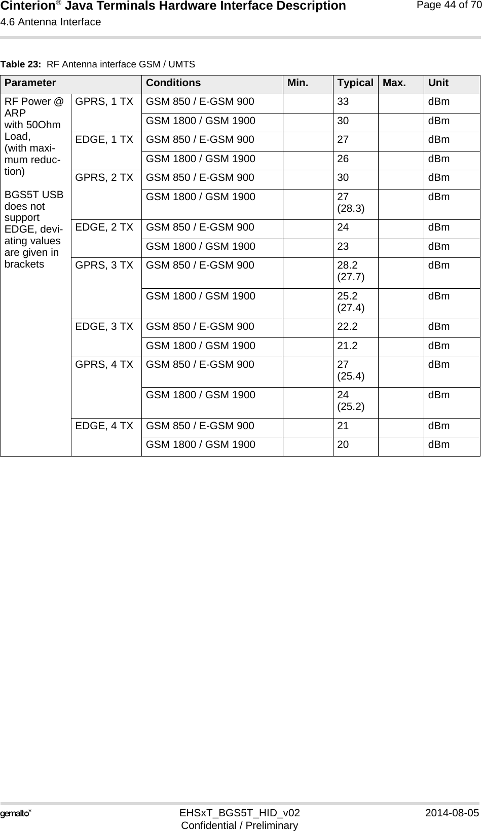
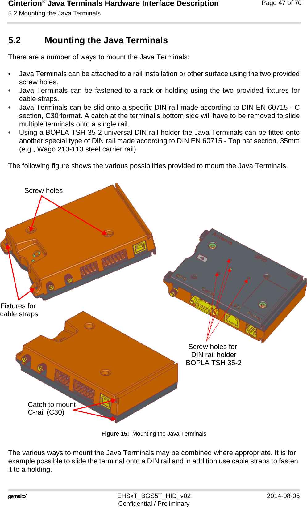
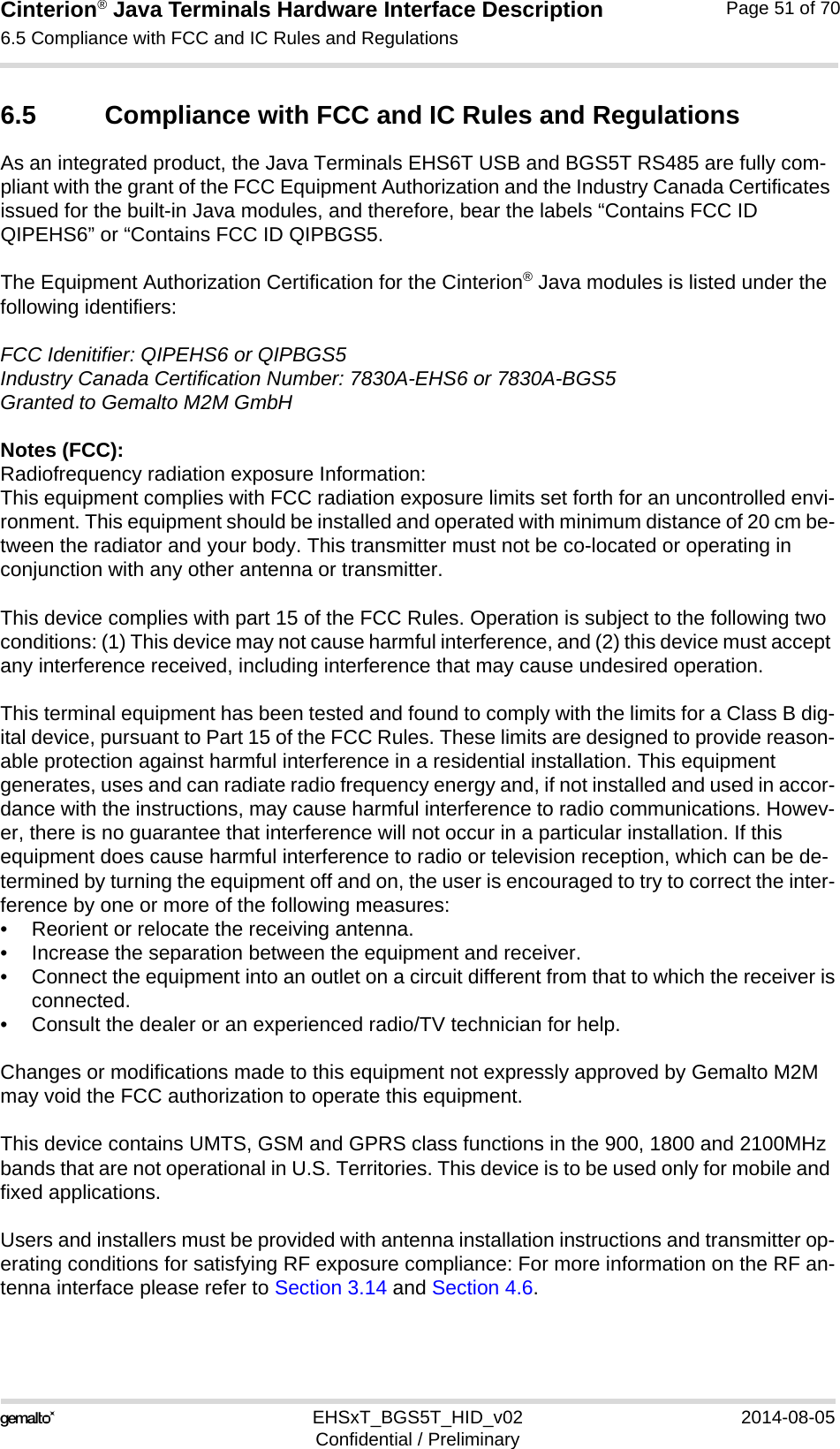
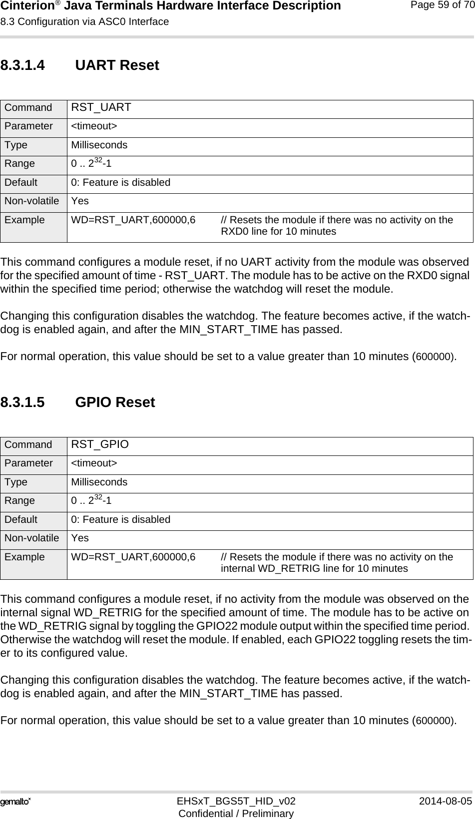
![Cinterion® Java Terminals Hardware Interface Description1.1 Related Documents16EHSxT_BGS5T_HID_v02 2014-08-05Confidential / PreliminaryPage 9 of 701.1 Related Documents[1] AT Command Set for your Java Terminal product[2] Release Notes for your Java Terminal productTo visit the Gemalto M2M GmbH Website please use the following link:http://m2m.gemalto.com1.2 Terms and AbbreviationsTable 2: Terms and abbreviationsAbbreviation DescriptionARP Antenna Reference PointATC AT CommandBTS Base Transceiver StationCB Cell BroadcastCODEC Coder-DecoderDCE Data Circuit terminating EquipmentDSR Data Set ReadyDTR Data Terminal ReadyEFR Enhanced Full RateEGSM Enhanced GSMEMC Electromagnetic CompatibilityESD Electrostatic DischargeETS European Telecommunication StandardFDMA Frequency Division Multiple AccessG.C.F. GSM Conformity ForumGSM Global Standard for Mobile CommunicationHW HardwareIC Integrated CircuitIF Intermediate Frequency IMEI International Mobile Equipment IdentifierI/O Input/ OutputIGT IgnitionISO International Standards OrganizationITU International Telecommunications Unionkbps kbits per secondLVD Low voltage Directive](https://usermanual.wiki/THALES-DIS-AlS-Deutschland/EHS6T.User-Manual/User-Guide-2348367-Page-9.png)
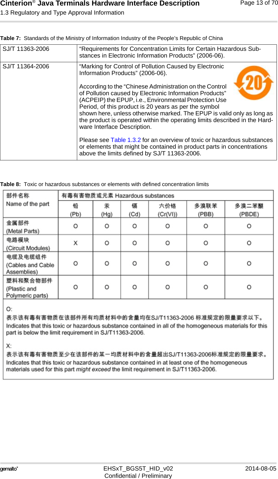
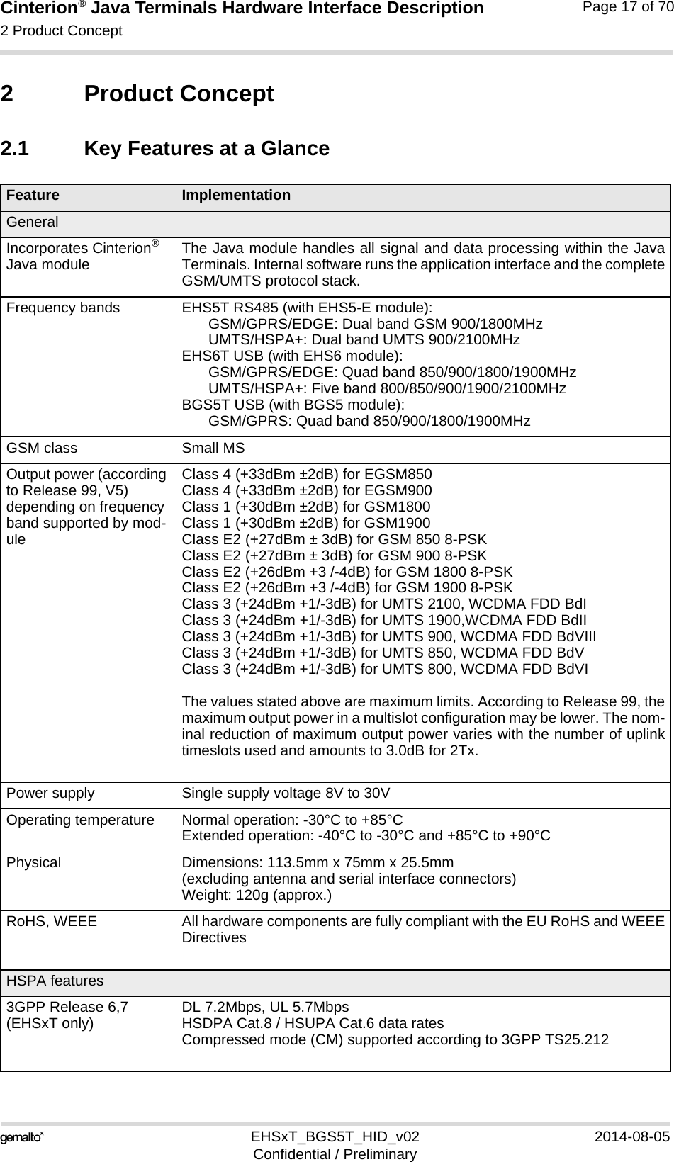
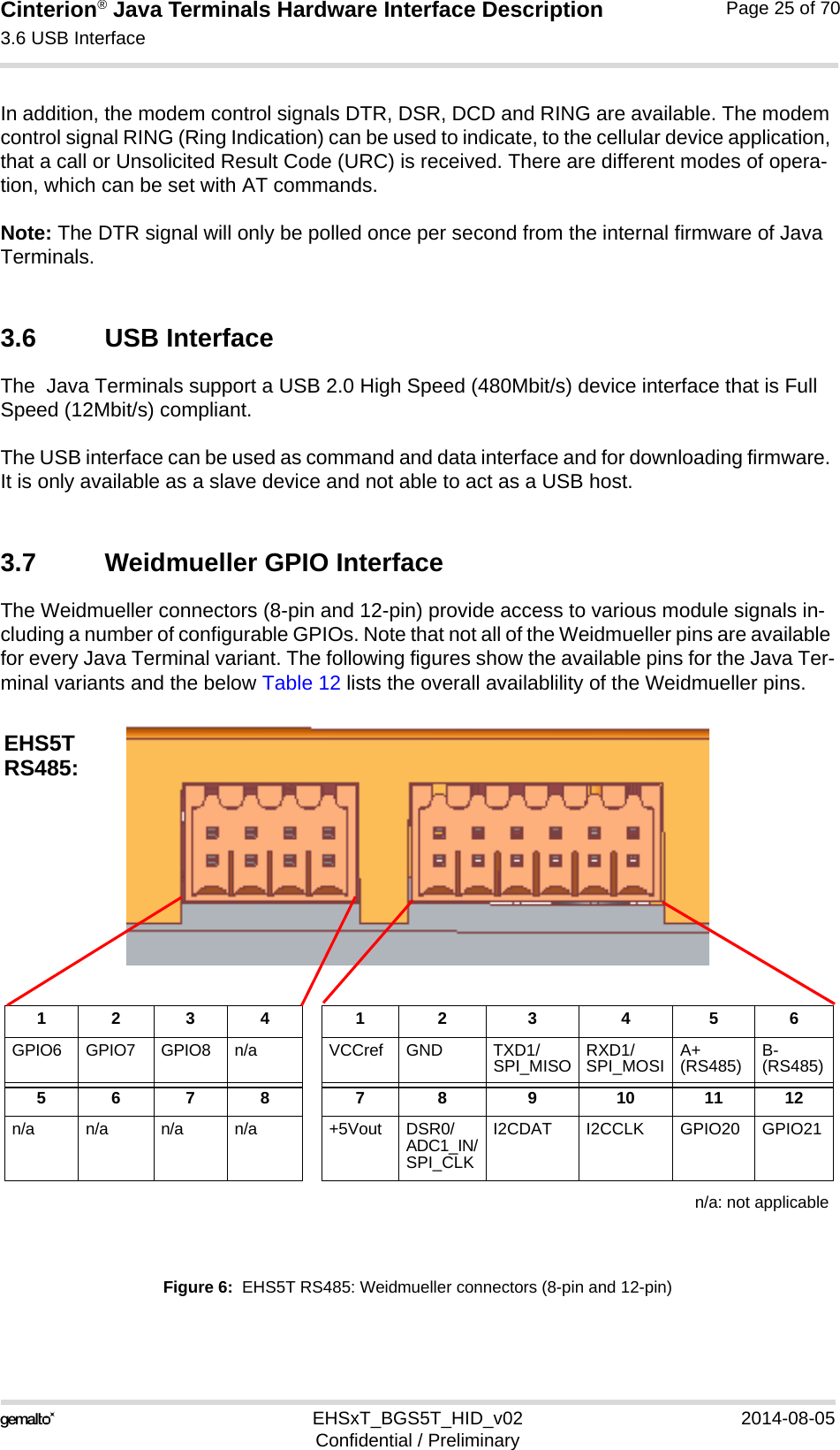
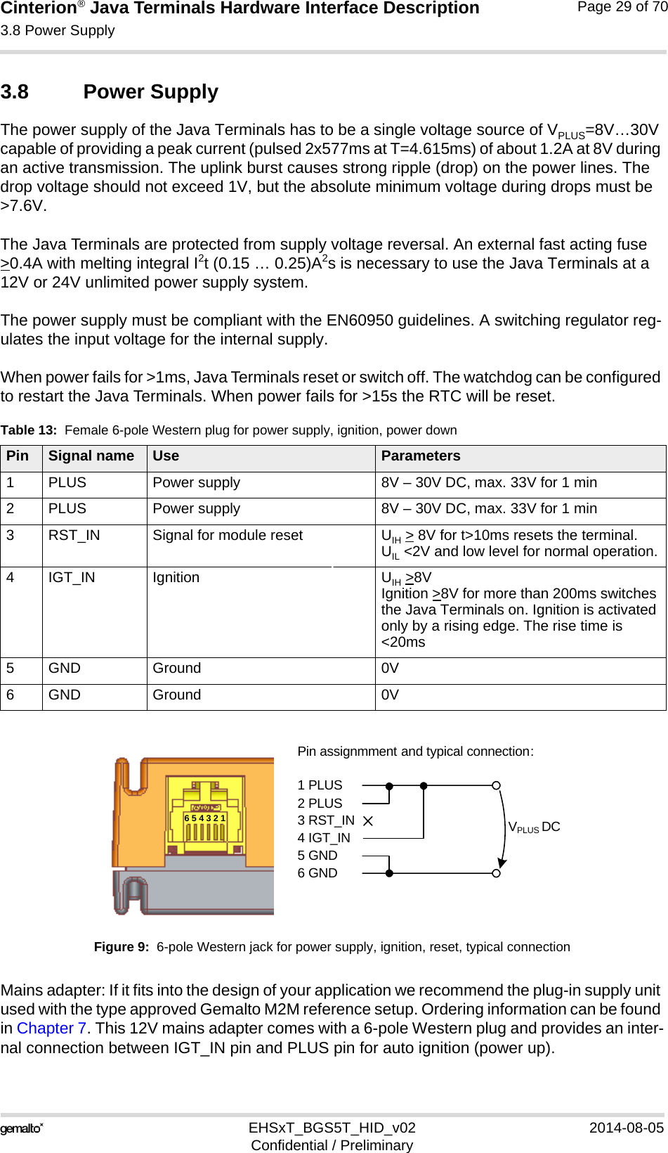
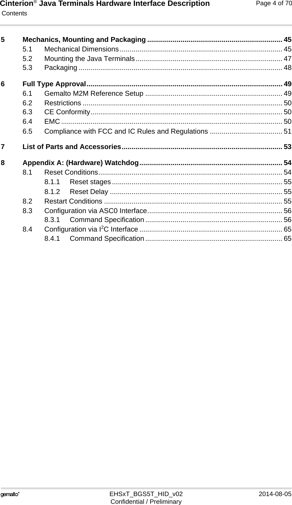
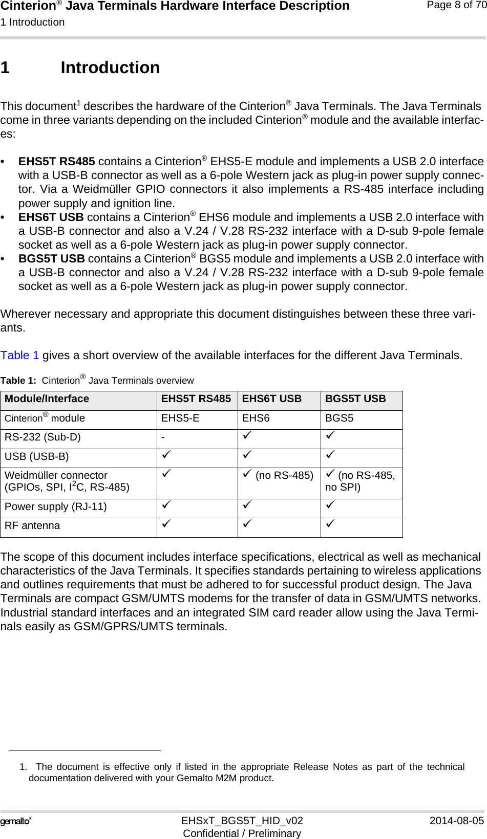
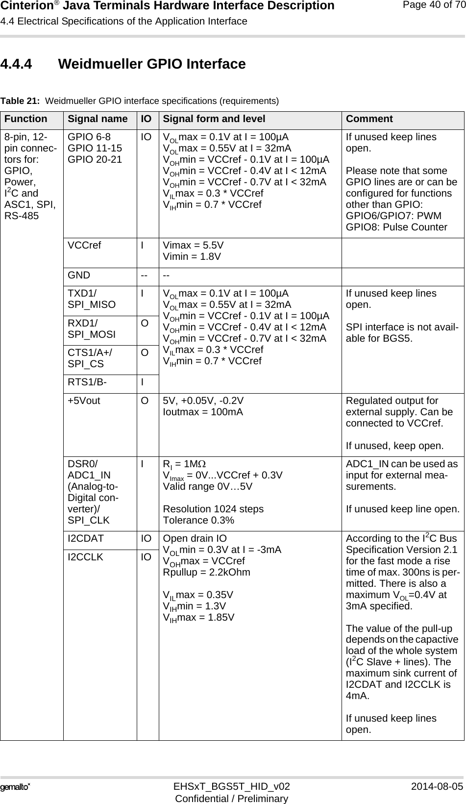
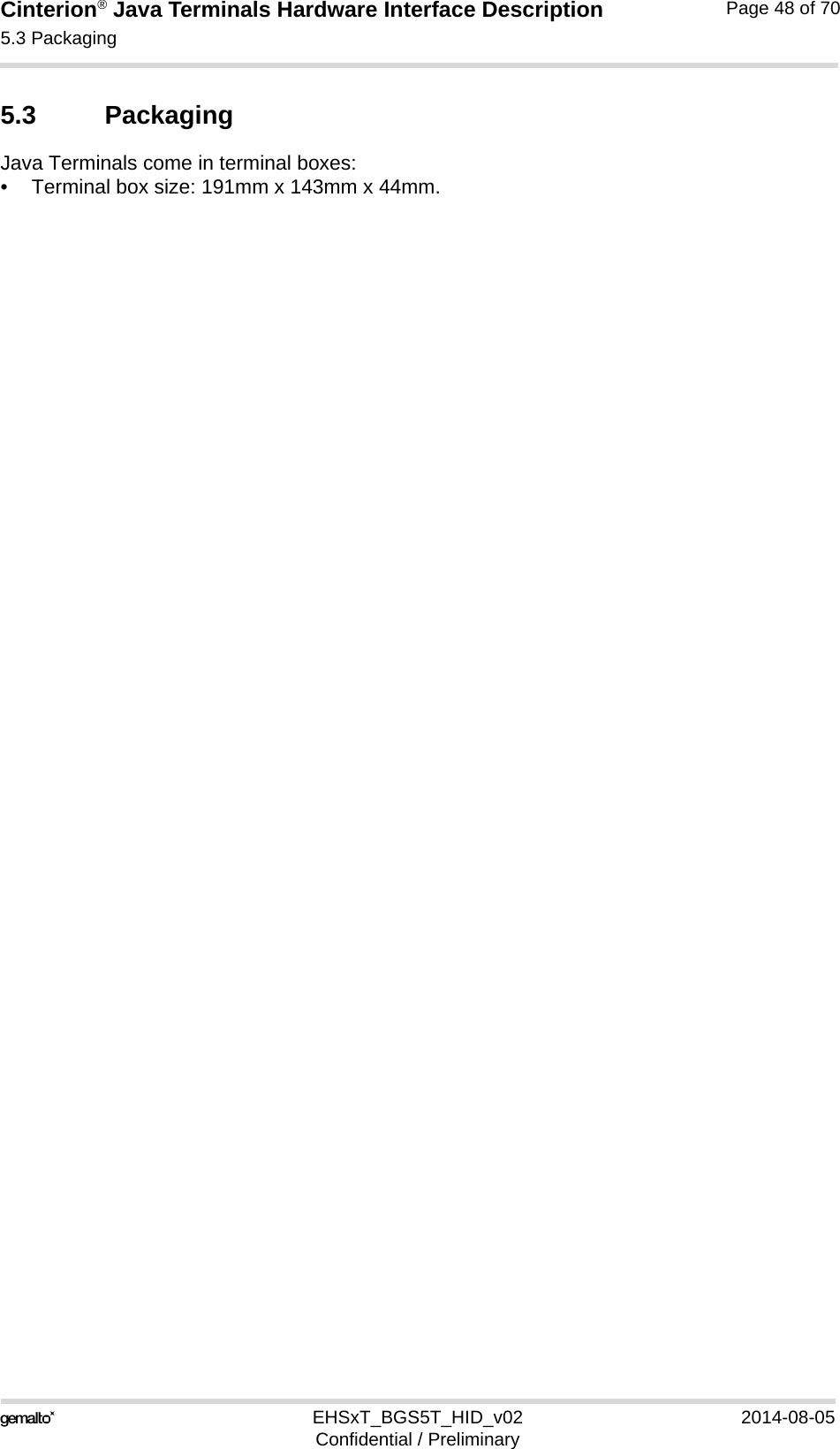
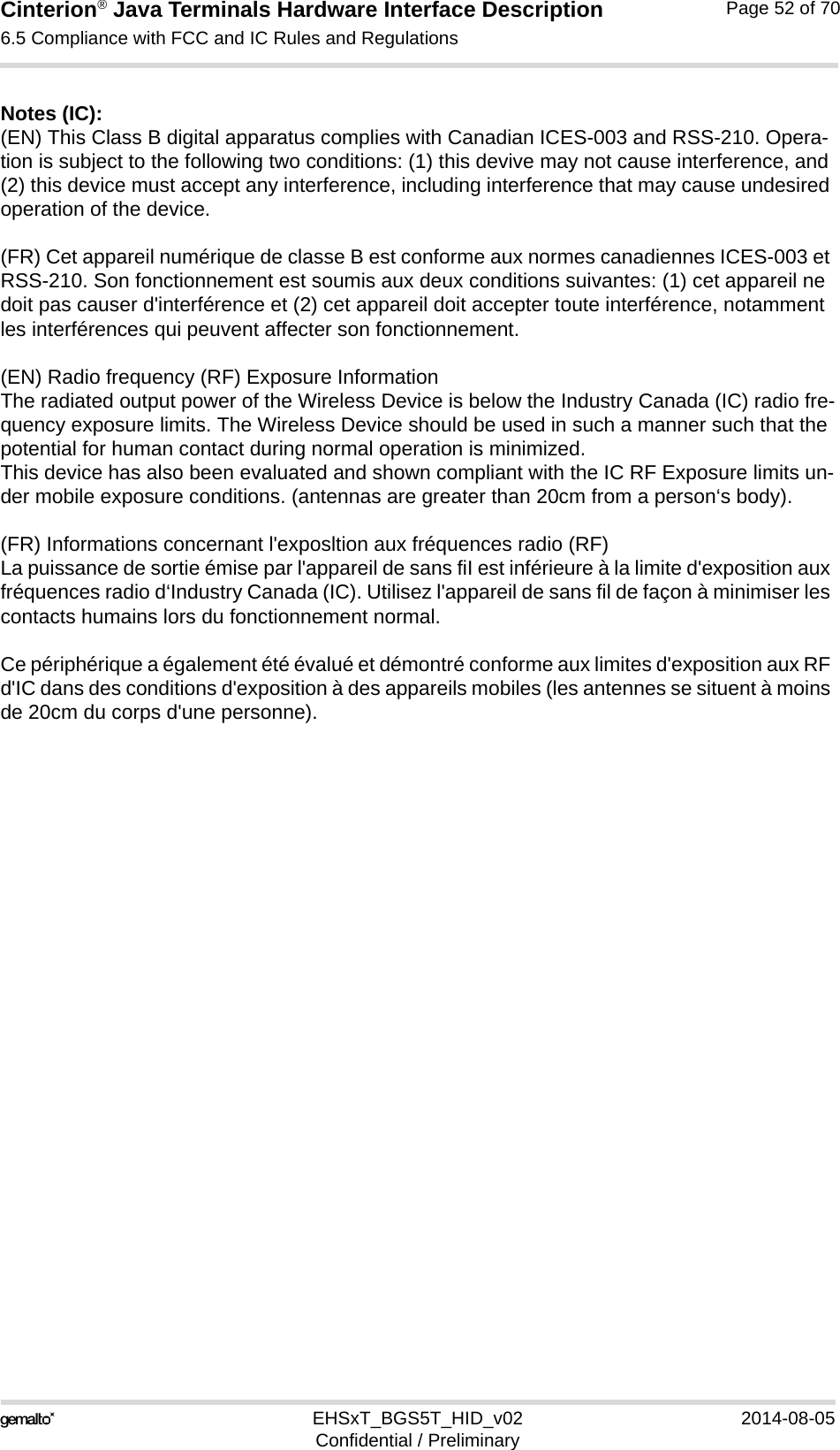
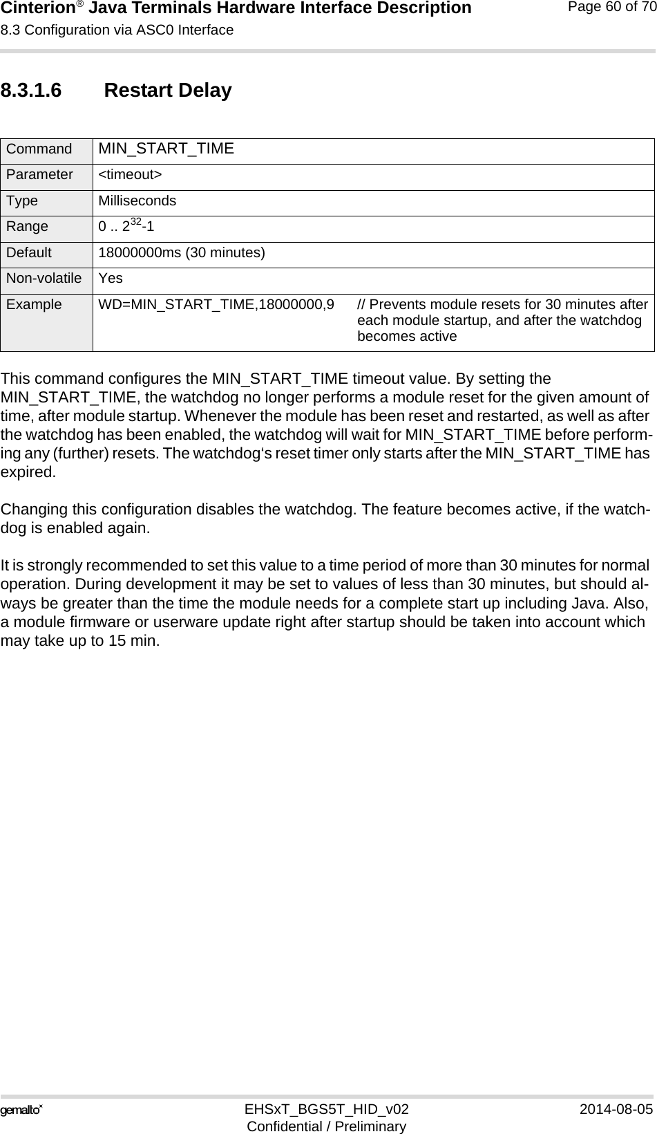
![Cinterion® Java Terminals Hardware Interface Description3.8 Power Supply35EHSxT_BGS5T_HID_v02 2014-08-05Confidential / PreliminaryPage 30 of 703.8.1 Turn Java Terminals onJava Terminals are turned on by plugging an appropriate power supply unit between PLUS and GND of the 6-pole Western jack. While the RST_IN pin (pin 3) is not active (voltage <2V) you can start the Java Terminals by activating the RS-232 DTR line if in POWER DOWN mode.The IGT_IN signal (pin 4) may be used to switch on Java Terminals if in POWER DOWN mode.The watchdog can also be configured to turn the Java Terminals on if in POWER DOWN mode.After startup of the Java Terminals the RS-232 lines are in an undefined state for approx. 900ms. This may cause undefined characters to be transmitted over the RS-232 lines during this period.3.8.2 Reset Java TerminalsAn easy way to reset the Java Terminals is entering the command AT+CFUN=x,1. For details on AT+CFUN please see [1].The watchdog can also be configured to reset the Java Terminals if in POWER DOWN mode.As an alternative, you can shut down the Java Terminals as described in Section 3.8.3 and then restart it as described in Section 3.8.1.3.8.3 Turn Java Terminals offNormal shutdown:• To turn off the Java Terminals use the AT^SMSO command, rather than disconnecting themains adapter. This procedure lets the Java Terminals log off from the network and allows the software toenter a secure state and save data before disconnecting the power supply. After AT^SMSOhas been entered the Java Terminals returns the following result codes: ^SMSO: MS OFFOK^SHUTDOWNThe "^SHUTDOWN" result code indicates that the Java Terminals turns off in less than1 second. After the shutdown procedure is complete the Java Terminals enters thePOWER DOWN mode. The yellow LED stops flashing (see Section 3.13 for a detailed LEDdescription). The RTC is still fed from the voltage regulator in the power supply ASIC.Please note that if there is an auto ignition connection between PLUS and IGT_IN the mod-ule will restart automatically after a normal shutdown.](https://usermanual.wiki/THALES-DIS-AlS-Deutschland/EHS6T.User-Manual/User-Guide-2348367-Page-30.png)
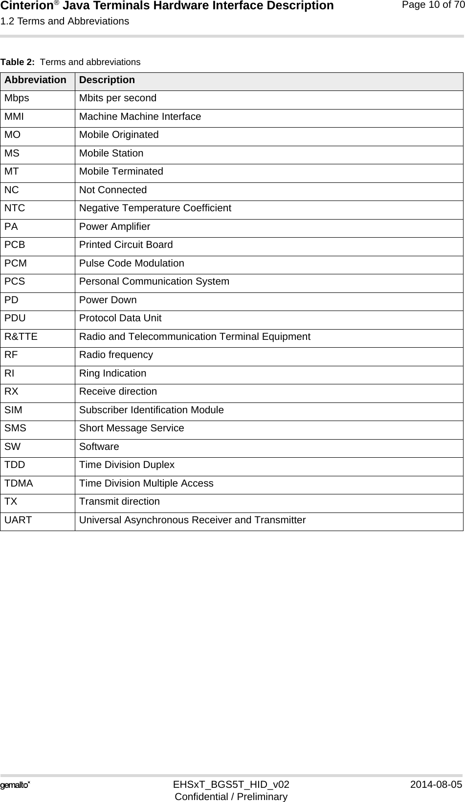
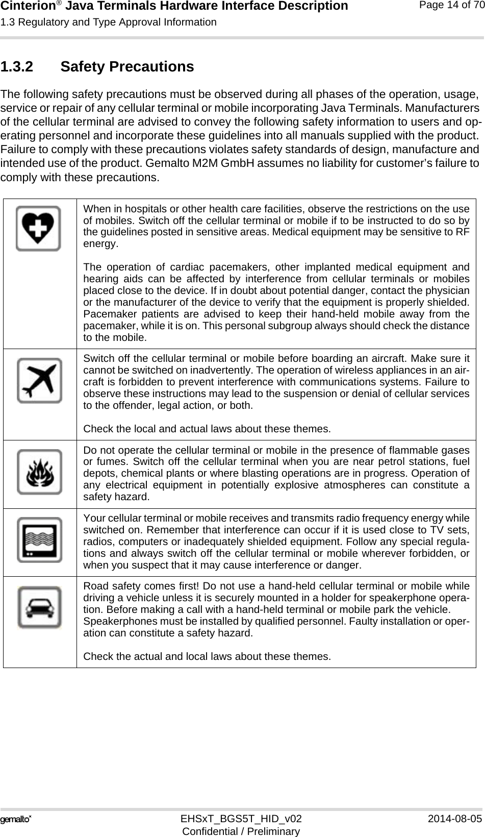
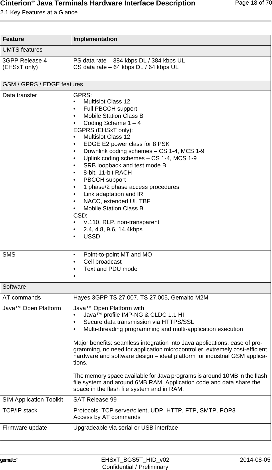
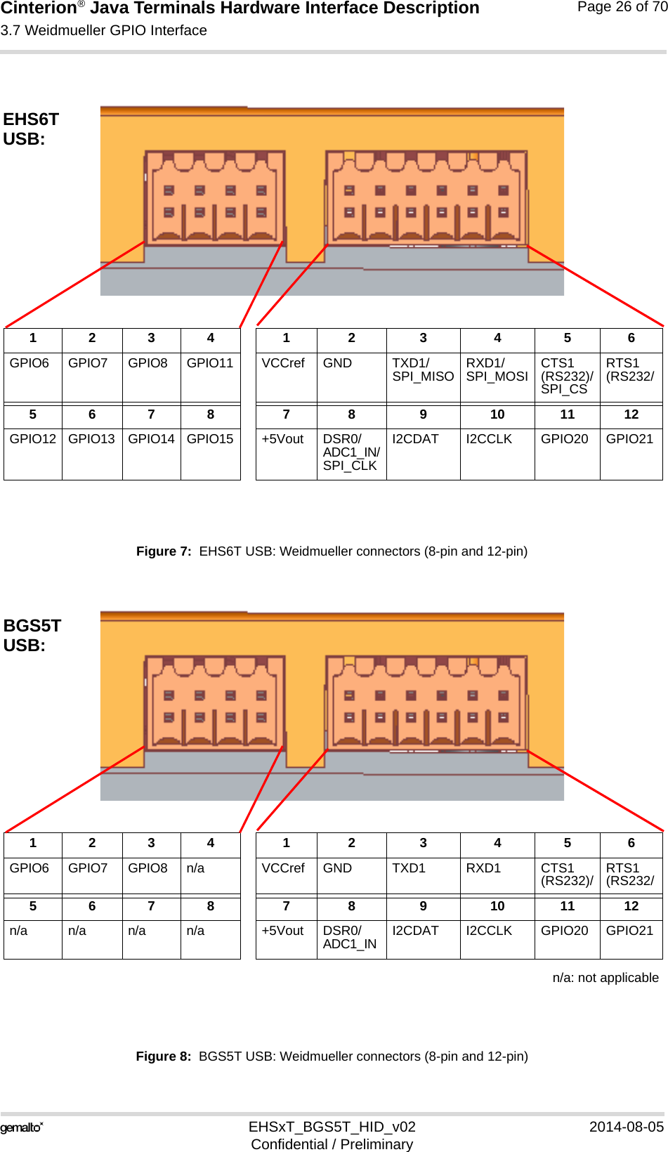
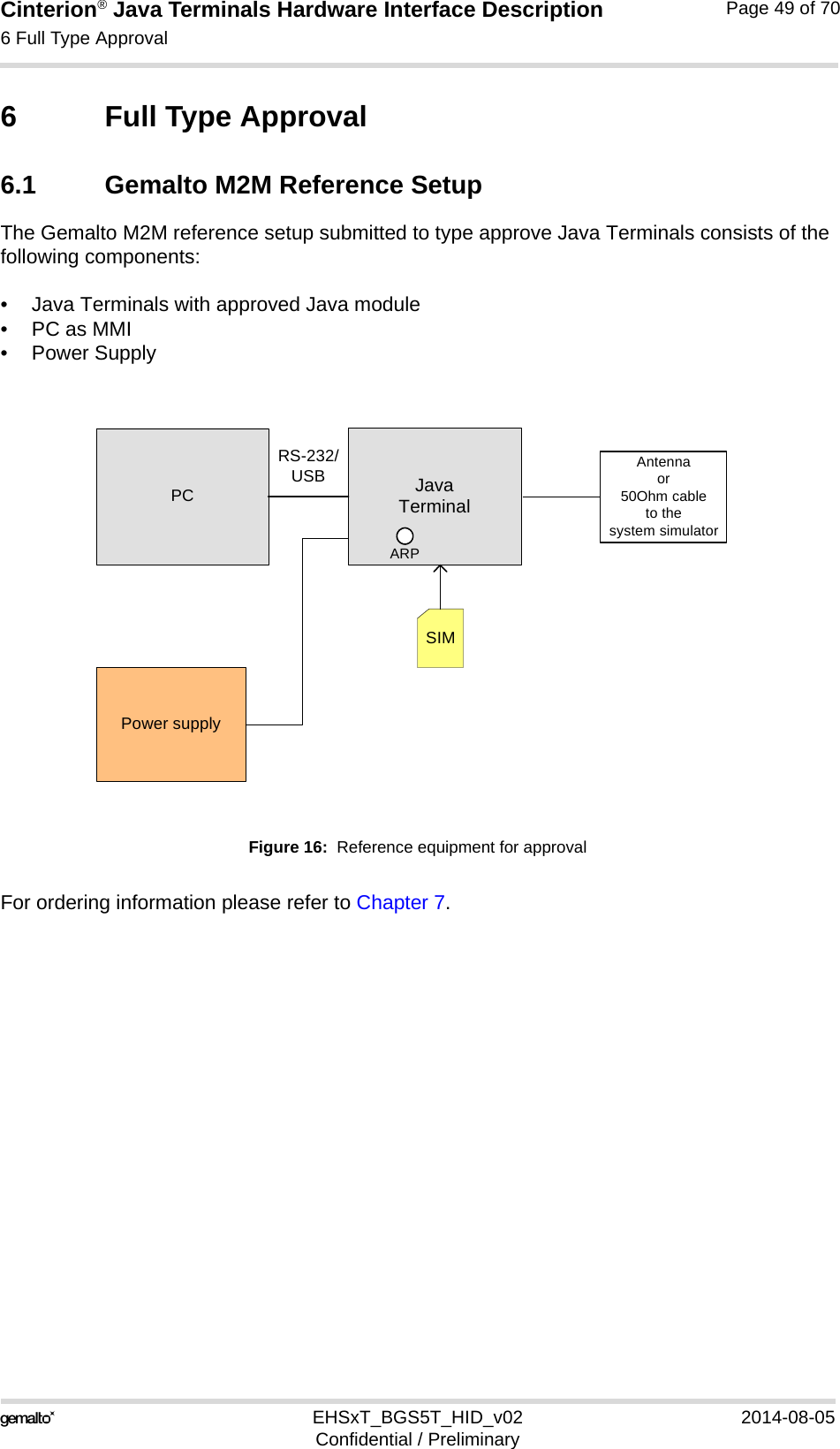
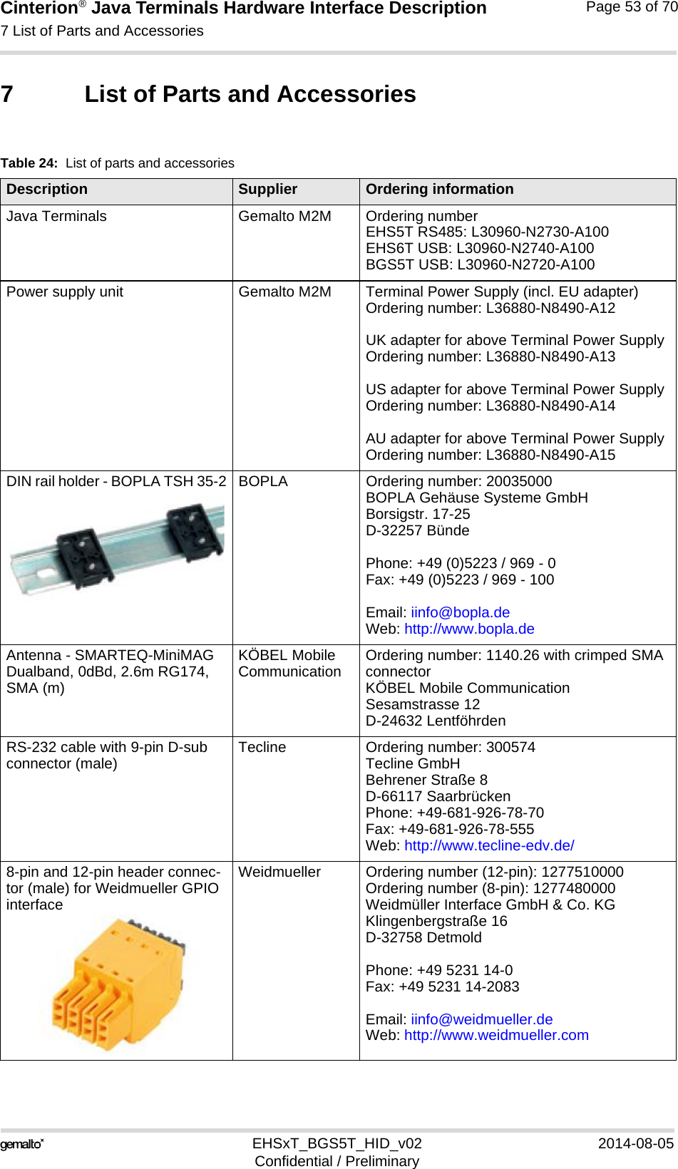
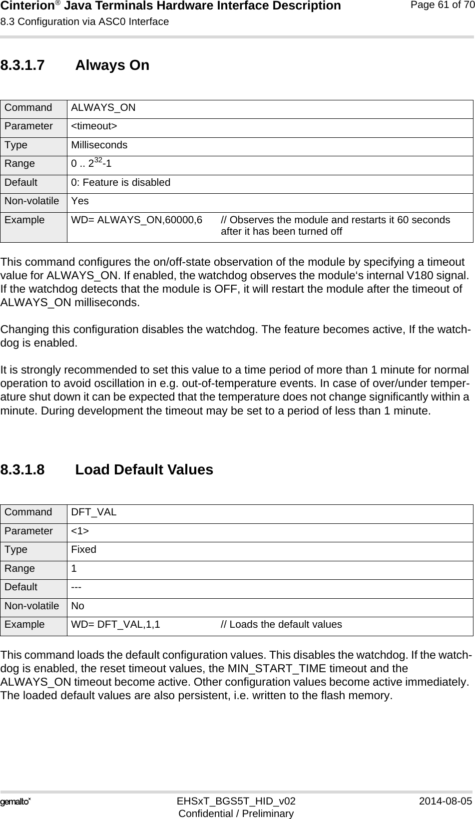
![Cinterion® Java Terminals Hardware Interface Description3.9 Automatic thermal shutdown35EHSxT_BGS5T_HID_v02 2014-08-05Confidential / PreliminaryPage 32 of 703.9 Automatic thermal shutdownAn on-board NTC measures the temperature of the built-in BGS2 module. If over- or undertem-perature is detected on the module the Java Terminals automatically shut down to avoid ther-mal damage to the system. Table 17 specifies the ambient temperature threshold for the Java Terminals. The automatic shutdown procedure is equivalent to the power-down initiated with the AT^SMSO command, i.e. Java Terminals log off from the network and the software enters a secure state avoiding loss of data. In IDLE mode it takes typically one minute to deregister from the network and to switch off. Alert messages transmitted before the Java Terminals switch off are implemented as Unsolic-ited Result codes (URCs). For details see the description of AT^SCTM command provided in [1]. Thermal shutdown will be deferred if a critical temperature limit is exceeded, while an emer-gency call or a call to a predefined phone number is in progress, or during a two minute guard period after power up. See [1] for details.The watchdog can be configured to restart the Java Terminals after a defined period.3.10 Hardware WatchdogThe Java Terminals feature a programmable hardware watchdog that permanently monitors the terminals‘ hardware and can be configured to react to various hardware states. The watch-dog may for example be configured to periodically restart the terminal, independant of its cur-rent operating state. Figure 4 shows how the watchdog is integrated into the Java Terminals.Please refer to Chapter 8 for details on how to control and configure the hardware watchdog.3.11 RTCThe internal Real Time Clock (RTC) of the Java Terminals retains the time and date and han-dles the alarm (reminder) function. The AT+CCLK command serves to set the time and date, and AT+CALA specifies a reminder message. See [1] for details. A dedicated voltage regulator backs up the RTC even in Power Down mode and enables Java Terminals to keep track of time and date. However, please note that the Alarm mode described in [1], Section AT+CALA, is not intended for the Java Terminals. The AT+CALA command can only be used to set a reminder message, but not to configure the mobile to wake up from POWER DOWN mode into Alarm mode. There-fore, after setting a timer with AT+CALA be sure not to shut down the Java Terminals by AT^SMSO or RST_IN signal.](https://usermanual.wiki/THALES-DIS-AlS-Deutschland/EHS6T.User-Manual/User-Guide-2348367-Page-32.png)
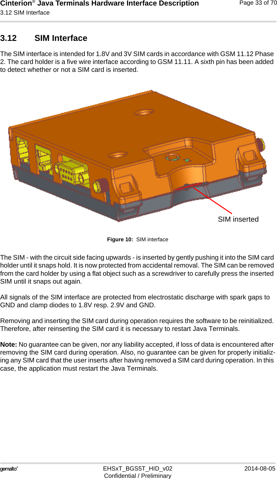
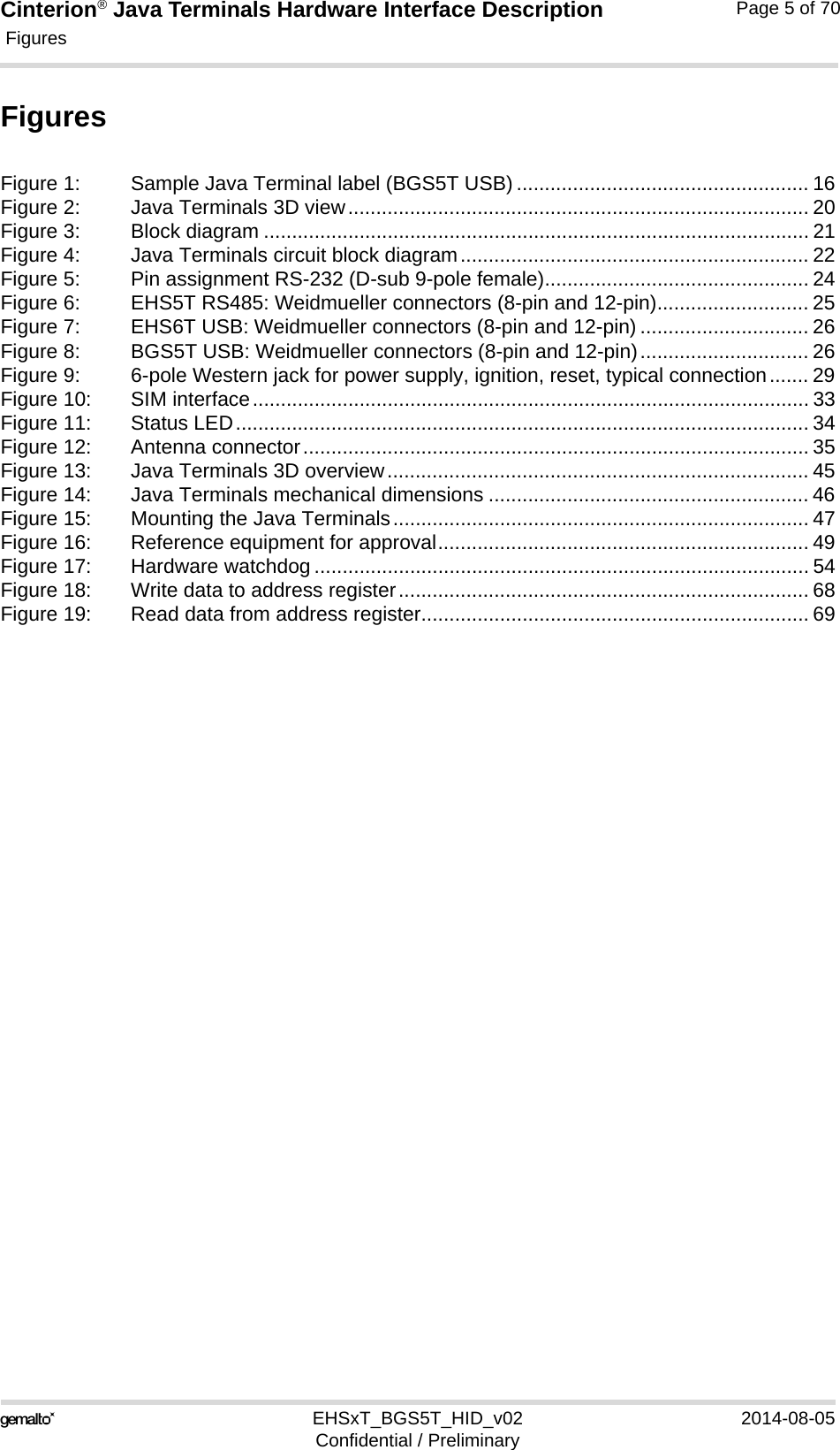
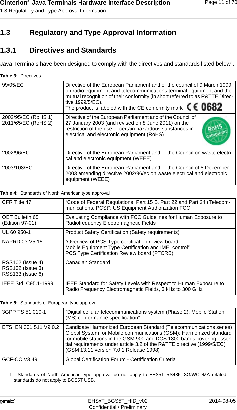
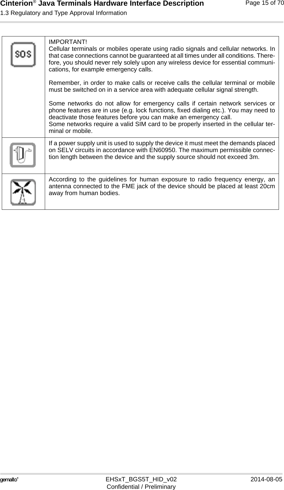
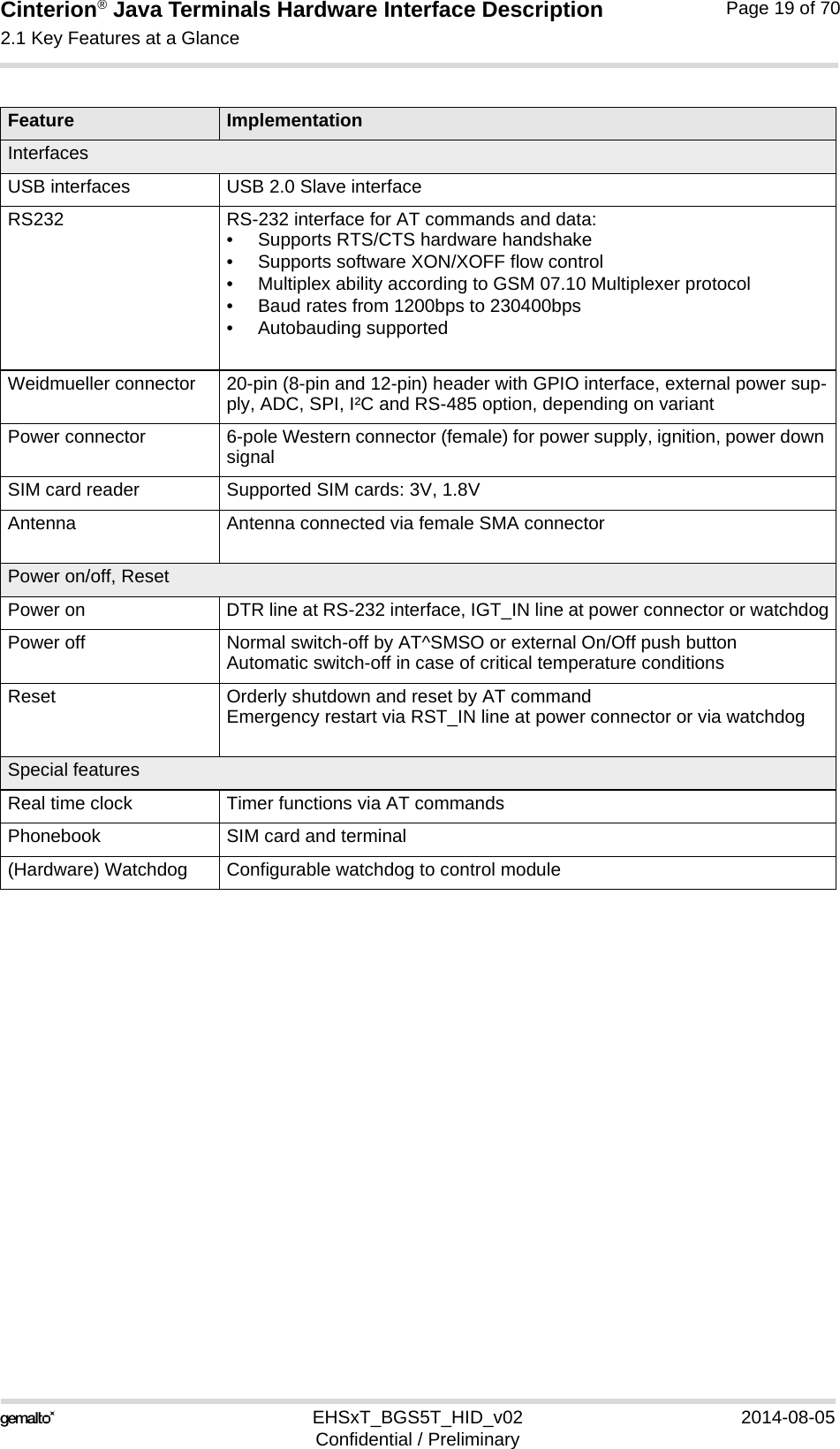
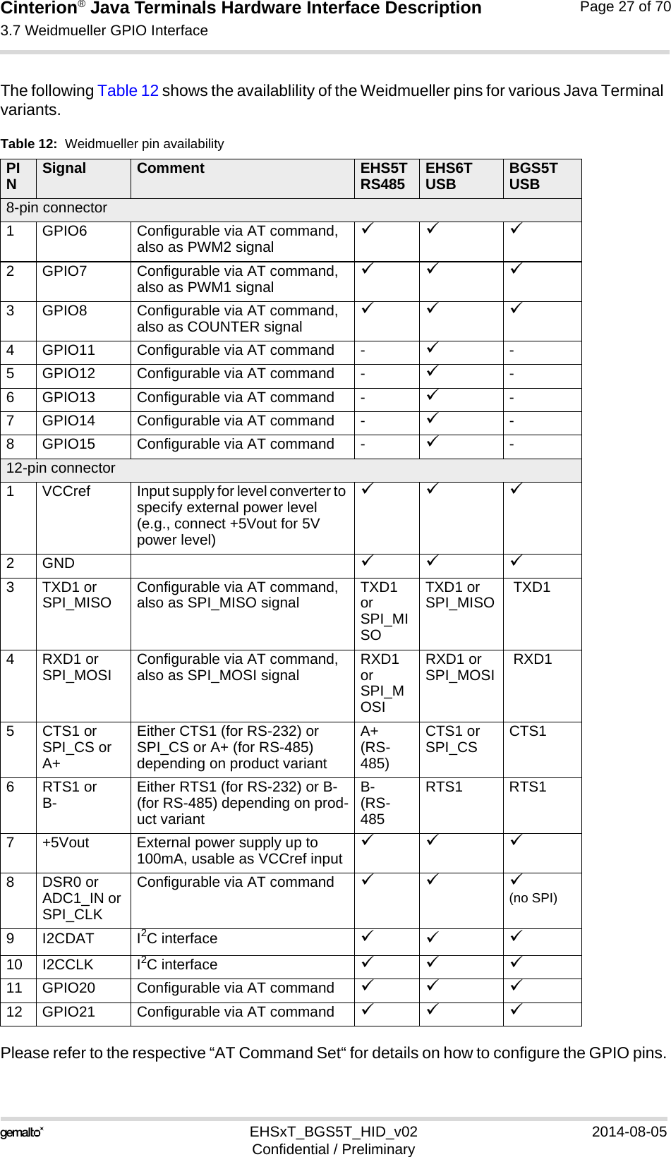
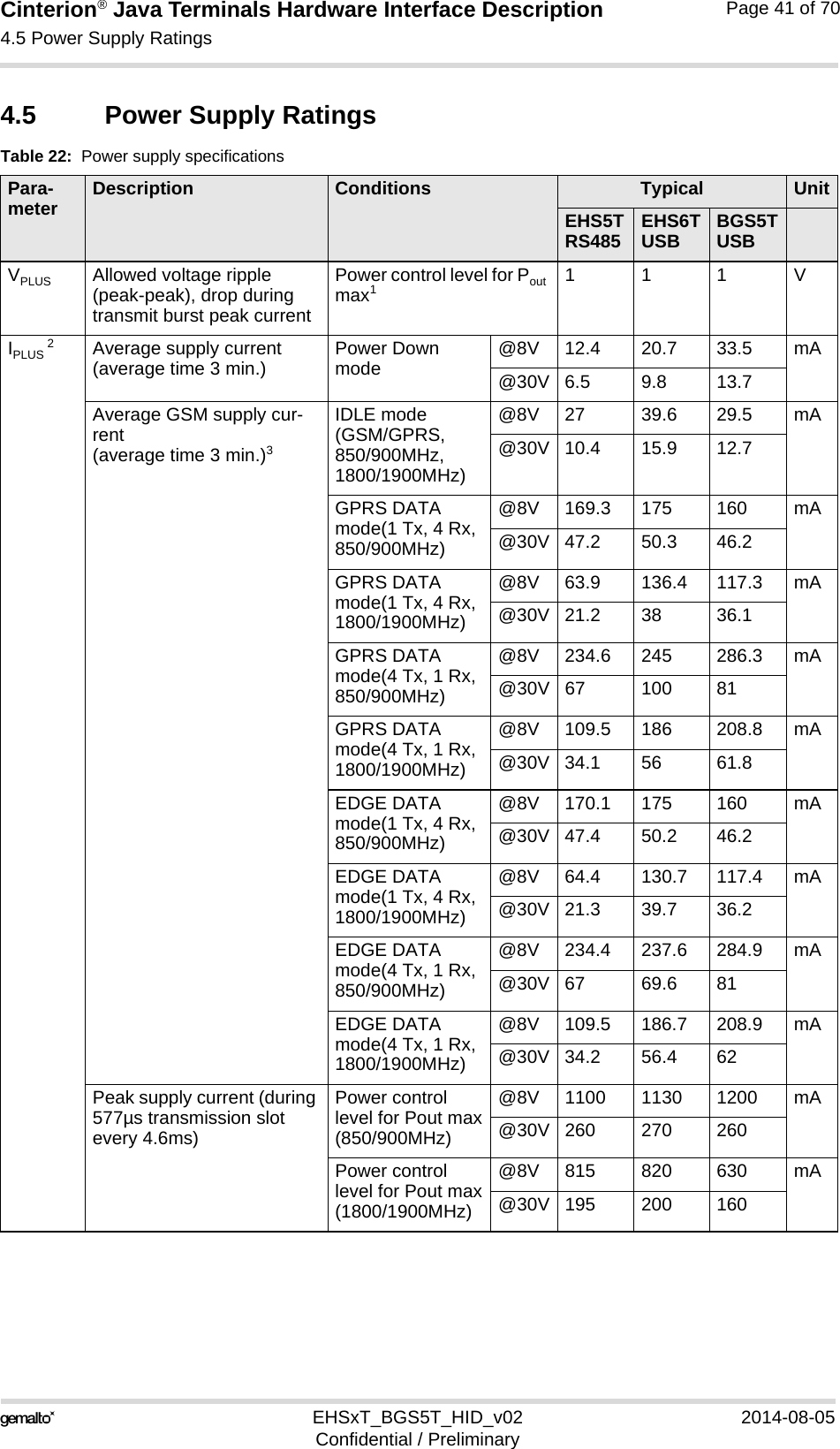
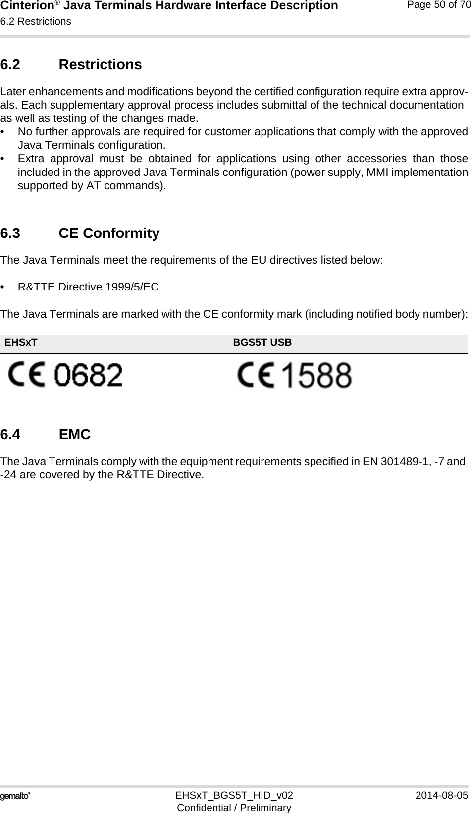
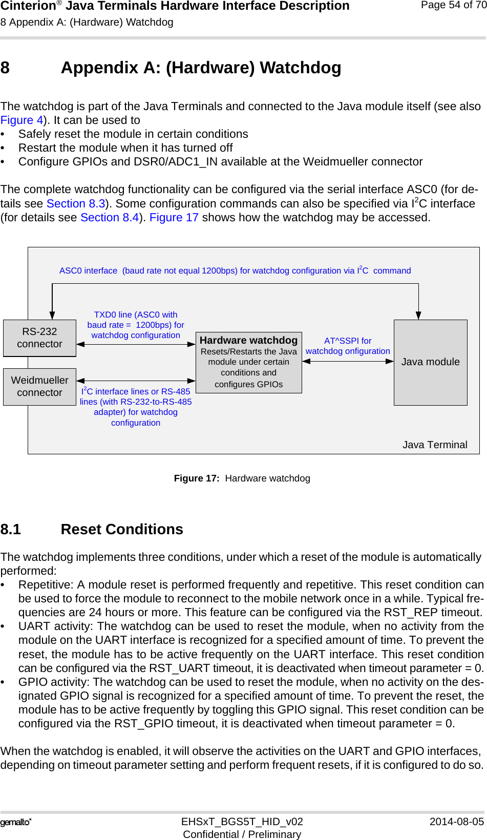
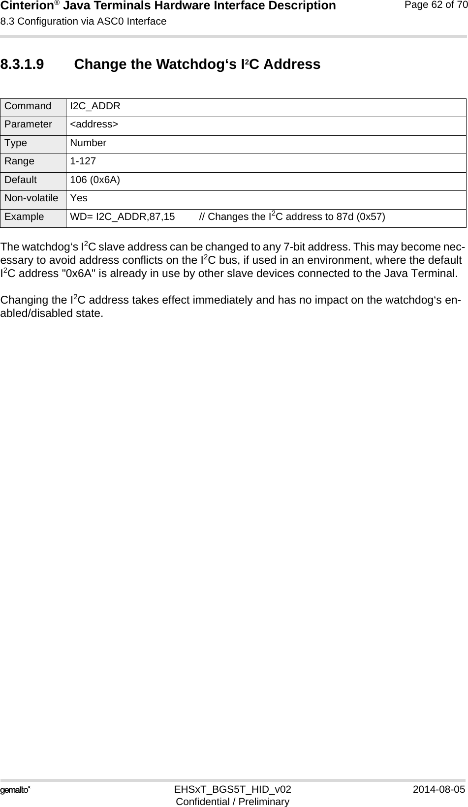
![Cinterion® Java Terminals Hardware Interface Description3.13 Status LEDs35EHSxT_BGS5T_HID_v02 2014-08-05Confidential / PreliminaryPage 34 of 703.13 Status LEDsJava Terminals have two LEDs indicating its operating states through the semitransparent cas-ing:• A green LED indicates whether the Java Terminals are ready to operate.• A yellow LED indicates the network registration state of the Java Terminals.Figure 11: Status LEDThe yellow LED is driven by a line of the integrated module that can be configured by using the AT^SLED command to either light permanently or to flash. For details on the AT command please refer to [1]. Green LED(Power on/off)Yellow LED(Network status)](https://usermanual.wiki/THALES-DIS-AlS-Deutschland/EHS6T.User-Manual/User-Guide-2348367-Page-34.png)
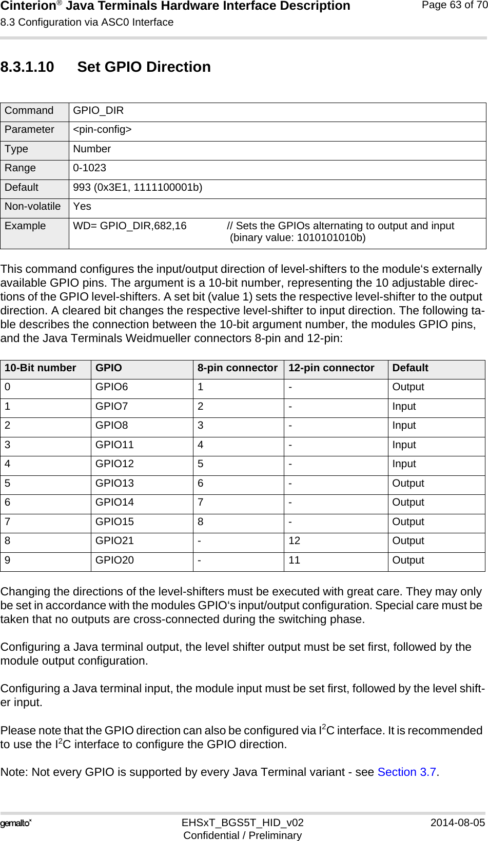
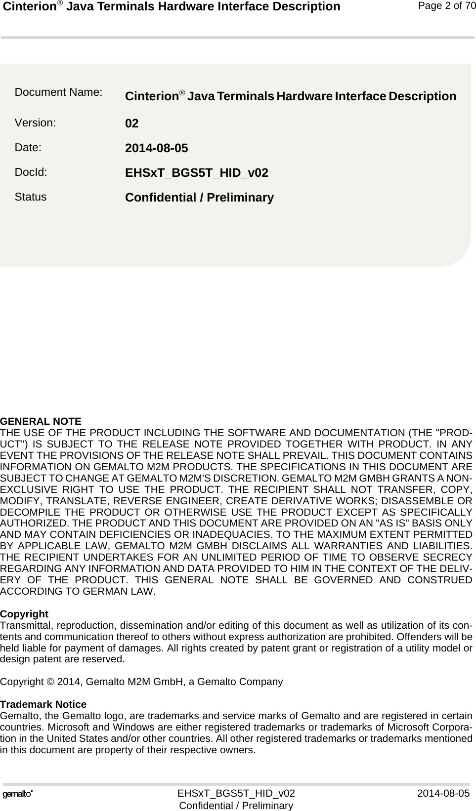
![Cinterion® Java Terminals Hardware Interface Description8.4 Configuration via I2C Interface69EHSxT_BGS5T_HID_v02 2014-08-05Confidential / PreliminaryPage 66 of 708.4.1.3 I2C Protocol OverviewIn write mode (i.e., slave address “0xD4“), one address byte and one data byte is sent to the Java Terminal/Watchdog. The address byte specifies a register to write the data byte to. The data byte value is only written, if it is valid, i.e., in the specified range. After a write attempt, the status code of the operation is saved and the read address register (RAR) is automatically set to the status register address (SR). A subsequent read command from the status register (SR) will then return the latest status code (see Table 26). Only when the address byte is the RAR, i.e. another register is selected to be read, the RAR is not automatically set to the SR register. See Section 8.4.1.4 for sample watchdog configurations via I2C.In read mode, one data byte can be read from the Java Terminal/Watchdog. Attempts to read more bytes will result in undefined values being returned by the device. The device will always return the value that is addressed by the RAR. To read a specific register, a write command with RAR as the address byte and the register to be read as the data byte has to be issued first. The next read will then return the value at this address. Note that there are only a few registers that can be read (see register table - Table 25). When the RAR is written with a non-read ad-dress, the RAR is set to the SR, and the status code ILLEGAL_ARGUMENT is saved. Note also that a consecutive read is not valid, as the return value will be ILLEGAL_ARGUMENT, but the caller cannot determine whether the result is the value at the faulty address or an error sta-tus code. See Section 8.4.1.4 for sample watchdog configurations via I2C.8.4.1.4 I2C CommandsThe following table lists the address register for configuration commands via I2C interface.Table 25: Address register for I2C commandsRegister address Read/Write Description Name Non-volatile Default Value range0x00 RStatus; only address register to read directly from. SR -OK See result codes Table 260x10 WGPIO6 GPIOxR Yes 10: Input1: Output0x11 WGPIO7 Yes 10x12 WGPIO8 Yes 10x13 WGPIO11 Yes 10x14 WGPIO12 Yes 00x15 WGPIO13 Yes 00x16 WGPIO14 Yes 00x17 WGPIO15 Yes 00x18 WGPIO21 Yes 00x19 WGPIO20 Yes 10x30 RGPIO direction Low Byte:Read out 8 bits for the GPIOs [15,14,13,12,11,8,7,6]GPIOLBR -[0..0xFF]0x31 RGPIO direction High Byte:Read out 2 bits for the GPIOs20 and 21 in the representation:[0,0,0,0,0,0,<20>,<21>]GPIOHBR -[0..0xFF]](https://usermanual.wiki/THALES-DIS-AlS-Deutschland/EHS6T.User-Manual/User-Guide-2348367-Page-66.png)
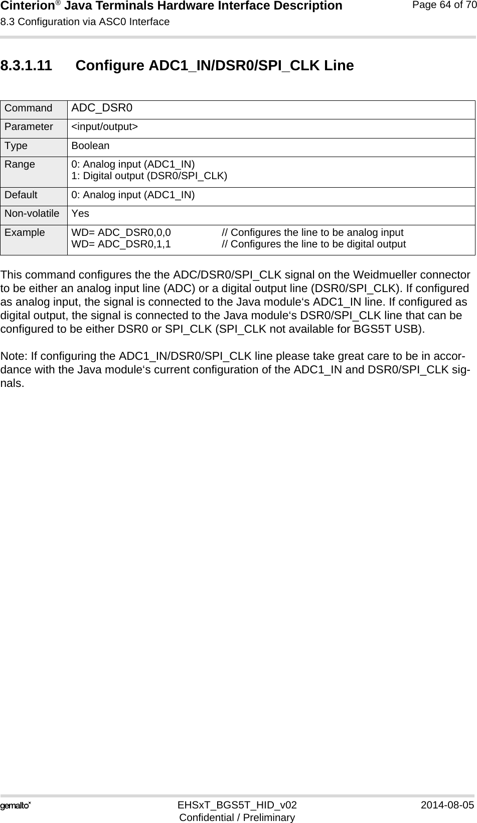
![Cinterion® Java Terminals Hardware Interface Description8.4 Configuration via I2C Interface69EHSxT_BGS5T_HID_v02 2014-08-05Confidential / PreliminaryPage 67 of 70Possible result codes for status command (see Section 8.4.1.3 and above Table 25):0x50 R/W ADC1_IN/DSR0 ADCDSRR Yes 0x00 0: Analog In1: Digital Out0x80 WTrigger delay. Specifies delay time for a reset. If a trigger delay time is specified, the watchdog is prevented from resetting the module for the given time.TDR No 0x00 Set time in min-utes.1...255: Minutes0: Disable0xFD RHardware watchdog‘s firmware version VER -- [0x00..0x99][MAJ MIN]4:MSB: MAJ4:LSB: MINMAJ: Main release number (e.g., 1.x)MIN: Sub release number (e.g., x.0)as in version v1.00xFF WRead address register (RAR) RAR No 0x00 0x00..0xFFOnly valid addresses contain valid valuesTable 26: I2C status result codesResult Code CommentOK 0x00 Last command was executed successfullyPROTOCOL_ERROR 0x01 Protocol error, i.e. wrong number of bytesILLEGAL_ADDRESS 0x02 Illegal register addressILLEGAL_ARGUMENT 0x03 Illegal argument. Argument is out of allowed range.UNDEFINED 0xFFTable 25: Address register for I2C commandsRegister address Read/Write Description Name Non-volatile Default Value range](https://usermanual.wiki/THALES-DIS-AlS-Deutschland/EHS6T.User-Manual/User-Guide-2348367-Page-67.png)
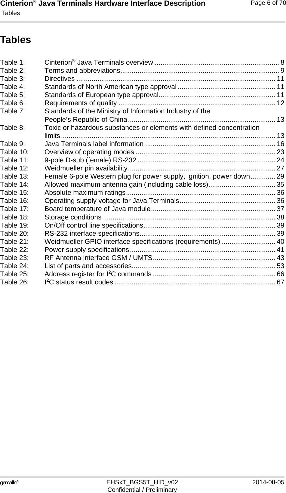
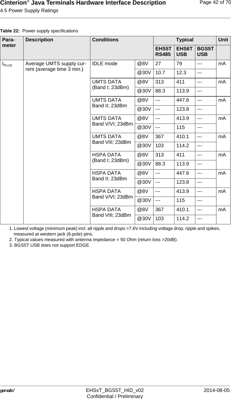
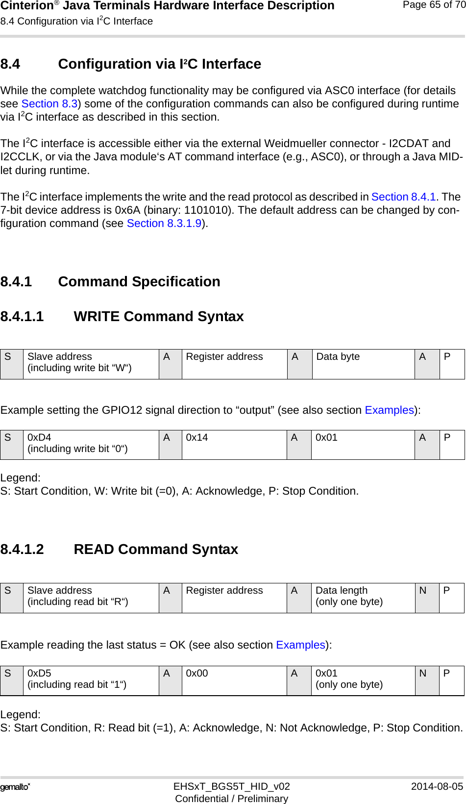
![Cinterion® Java Terminals Hardware Interface Description8.4 Configuration via I2C Interface69EHSxT_BGS5T_HID_v02 2014-08-05Confidential / PreliminaryPage 68 of 70ExamplesThe following two samples show how the watchdog can be configured via the I2C interface, us-ing the AT^SSPI command (at RS-232/ASC0) to transfer the I2C user data. Please refer to [1] for more information on the AT command AT^SSPI and on how to configure and control the data transfer over the I2C interface. The above Table 25 specifies the address register that can be used in I2C configuration com-mands.The first example sets GPIO12 to “output“. It therefore configures a write register marked as “W“ in Table 25. Figure 18: Write data to address registerAT^SSPI=CONNECT<aD41401>{a+}<bD50001>{b+00}#OKOpen the Java Terminals I2C data connection. Indicates that the connection is open.WRITE command enclosed by <>: “a“ is a command ID to better identify and match acknowledgments, “D4“ indicates the slave address (write mode), “14“ specifies the address register GPIO12, and “01“ sets the data byte (i.e., line is “output“). Note: The data byte value is only written if valid, i.e., if in the specified range. After a WRITE command, the status code of the operation is saved to the status register (SR) and a subsequent READ command from the status register will then return the latest status code as listed in Table 26.Acknowledgement enclosed in curly brackets of a successful data transmission.READ command enclosed by <>: “b“ is a command ID to better identify and match acknowledgements, “D5“ indicates the slave address (read mode), “00“ specifies the address register SR, and “01“ sets the data length to be read. Note: The READ command can only be called in conjunction with the SR address “00“ and the data length of one byte “01“.Acknowledgement enclosed in curly brackets of a successful data transmission, together with the response code “00“ indicating that the command was successful-ly executed.Close data connection.Connection closed.PC WatchdogWrite: Set GPIO12 to “output“ GPIO12:01SR:00Read from status register (SR)Command executed successfully](https://usermanual.wiki/THALES-DIS-AlS-Deutschland/EHS6T.User-Manual/User-Guide-2348367-Page-68.png)