THALES DIS AlS Deutschland GWM300 EHS6 GSM/WCDMA Terminal User Manual hid
Gemalto M2M GmbH EHS6 GSM/WCDMA Terminal hid
UserManual.wiki
>
THALES DIS AlS Deutschland
>
GWM300 User Manual
TempConfidential_QIPGWM300_User manual
Navigation menu
Upload a User Manual
Namespaces
Wiki Guide
HTML
PDF
Info
Views
User Manual
Discussion / Help
Navigation
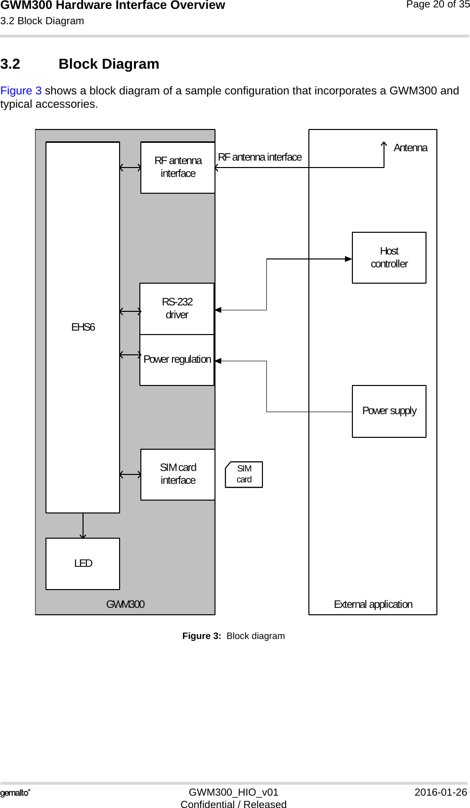
![GWM300 Hardware Interface Overview1.1 Related Documents15GWM300_HIO_v01 2016-01-26Confidential / ReleasedPage 8 of 351.1 Related Documents[1] AT Command Set for the Cinterion® EHS6 module[2] Release Notes for the Cinterion® EHS6 moduleTo visit the Gemalto M2M GmbH Website please use the following link:http://m2m.gemalto.com1.2 Terms and AbbreviationsTable 1: Terms and abbreviationsAbbreviation DescriptionACMA Australian Communications and Media AuthorityARP Antenna Reference PointATC AT CommandBTS Base Transceiver StationCB Cell BroadcastCE Communauté Européenne (originally)CODEC Coder-DecoderDAI Digital Audio InterfaceDCE Data Circuit terminating EquipmentDSR Data Set ReadyDTR Data Terminal ReadyEFR Enhanced Full RateEGSM Enhanced GSMEMC Electromagnetic CompatibilityESD Electrostatic DischargeETS European Telecommunication StandardFDMA Frequency Division Multiple AccessG.C.F. GSM Conformity ForumGSM Global Standard for Mobile CommunicationHW HardwareIC Integrated CircuitIF Intermediate Frequency IMEI International Mobile Equipment IdentifierI/O Input/ OutputIGT IgnitionISO International Standards Organization](https://usermanual.wiki/THALES-DIS-AlS-Deutschland/GWM300/User-Guide-2934837-Page-8.png)
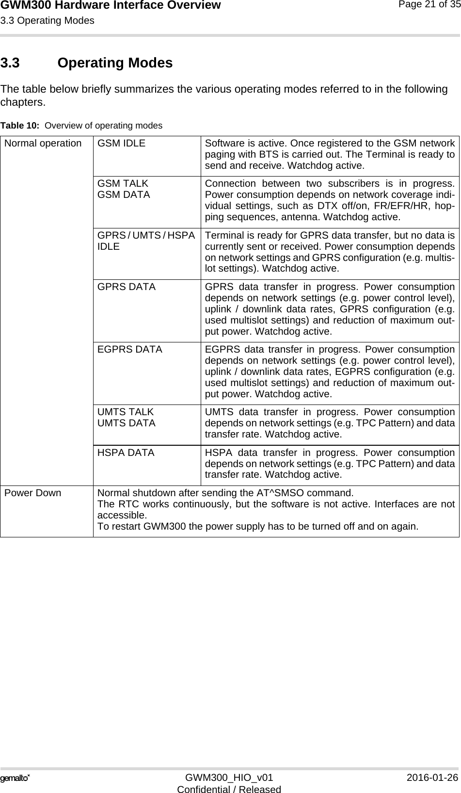
![GWM300 Hardware Interface Overview3.5 Power Up/Power Down Scenarios26GWM300_HIO_v01 2016-01-26Confidential / ReleasedPage 24 of 353.5 Power Up/Power Down ScenariosIn general, be sure not to turn on the GWM300 while it is beyond the safety limits of voltage stated in Section 4.1. GWM300 immediately switches off after having started and detected these inappropriate conditions. In extreme cases this can cause permanent damage to the GWM300.3.5.1 Turn GWM300 onGWM300 is automatically turned on and started into normal mode by plugging or by re-plug-ging an appropriate power supply unit at the power supply line BATT+. 3.5.2 Reset/Restart GWM300GWM300 can be reset/restarted by entering the command AT+CFUN=x,1. For details on AT+CFUN please see [1].3.5.3 Turn GWM300 offNormal shutdown:• To turn off the GWM300 use the AT^SMSO command, rather than disconnecting the mainsadapter. This switch off procedure lets the GWM300 log off from the network and allows the softwareto enter a secure state and save data before disconnecting the power supply. AfterAT^SMSO has been entered the GWM300 returns the following result codes: ^SMSO: MS OFFOK^SHUTDOWNThe "^SHUTDOWN" result code indicates that the GWM300 turns off in less than 1 second.After the shutdown procedure is complete the GWM300 enters the Power Down mode. TheRTC is still fed from the voltage regulator in the power supply ASIC.Only after power off and power on again, i.e., turning off and on the power supply line, can the terminal be switches on again. Apart from teh normal shutdown 3.5.4 Disconnecting Power SupplyBefore disconnecting the power supply from the BATT+ pin, make sure that the GWM300 is in a safe condition. The best way is to wait 1s after the "^SHUTDOWN" result code has been in-dicated.](https://usermanual.wiki/THALES-DIS-AlS-Deutschland/GWM300/User-Guide-2934837-Page-24.png)
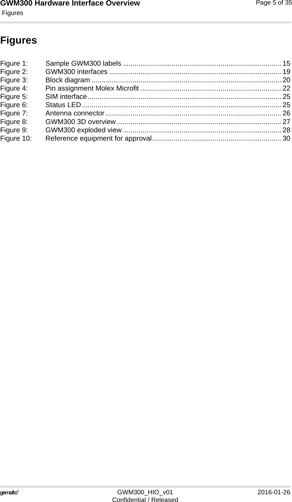
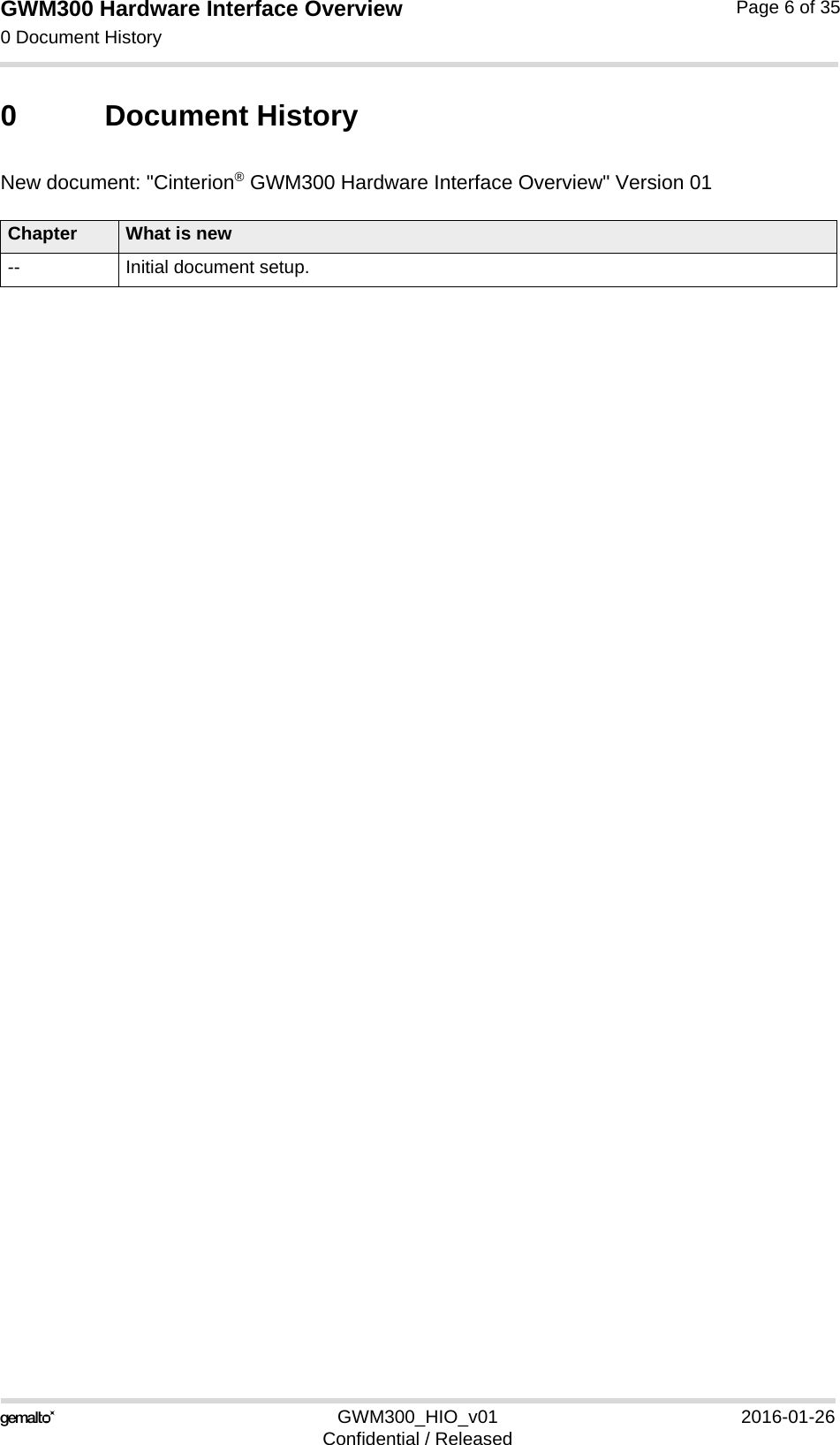
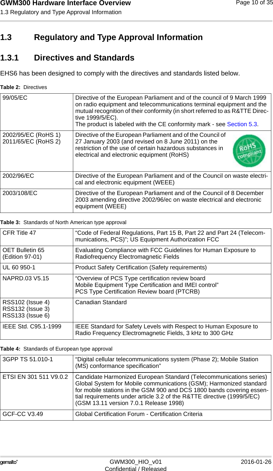
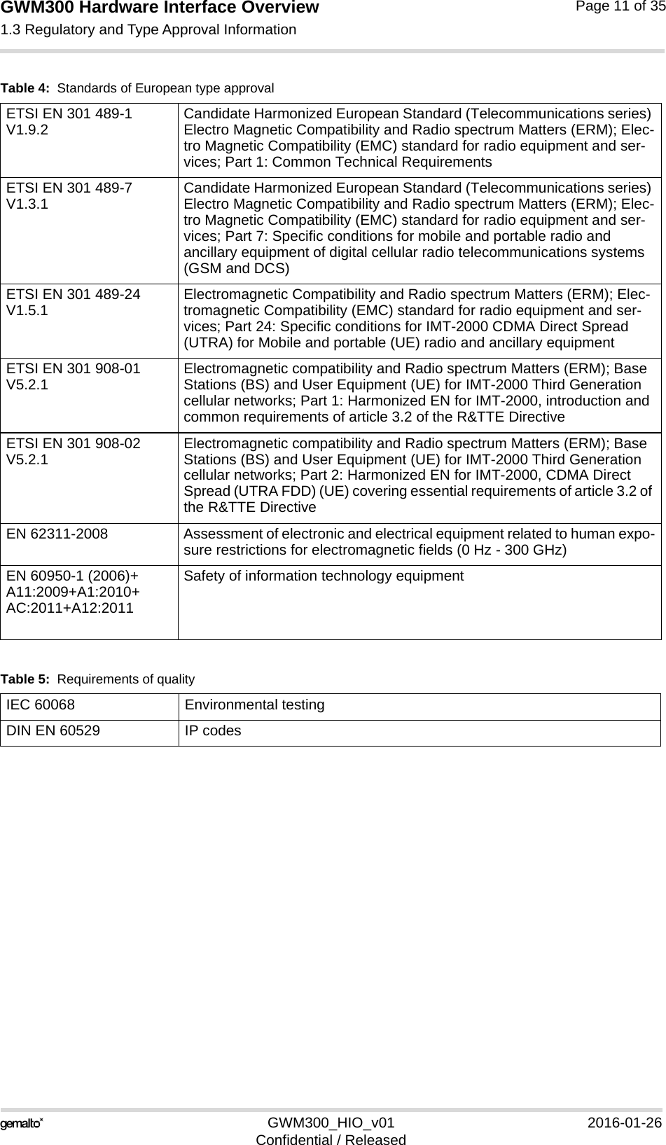
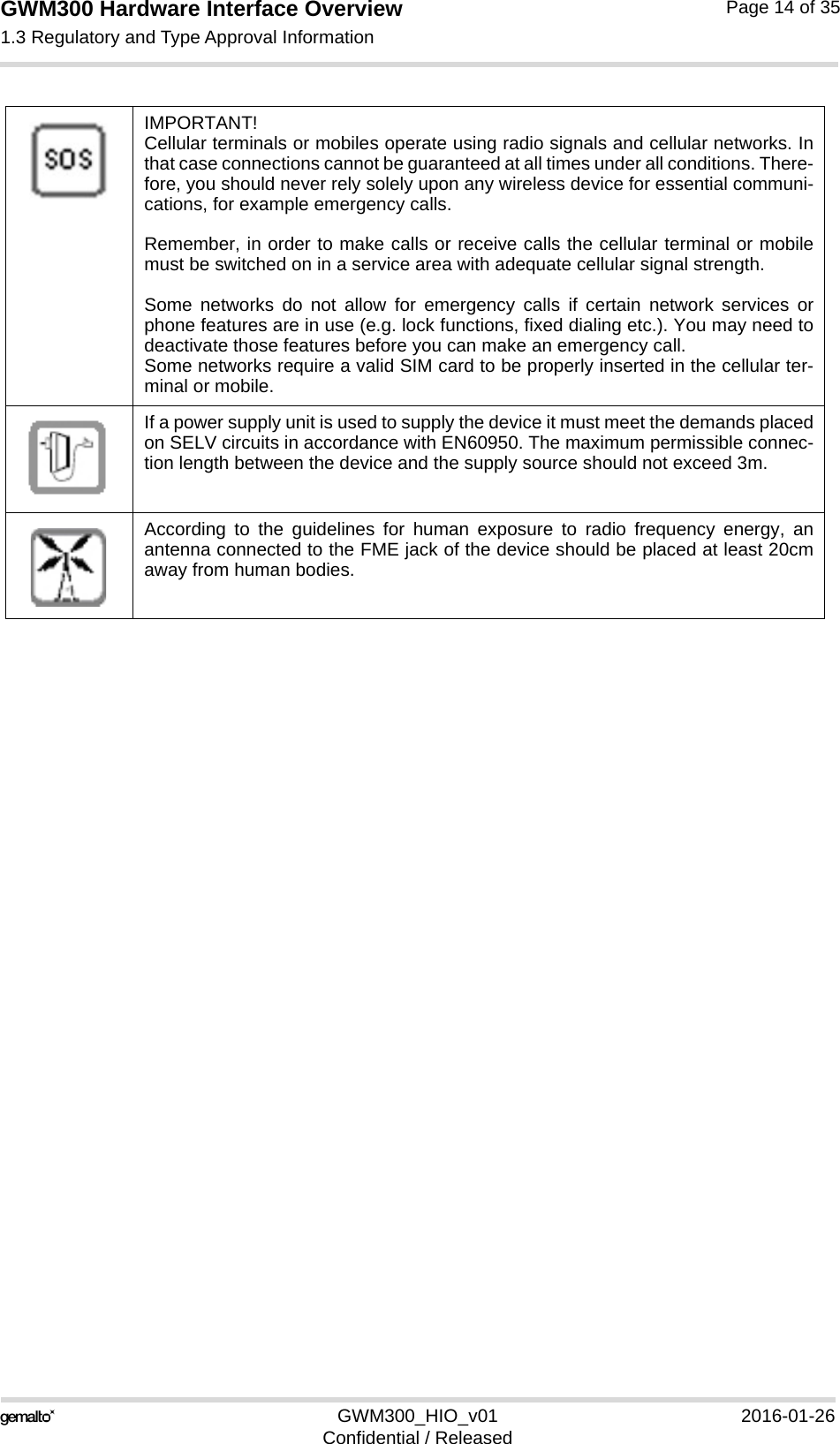
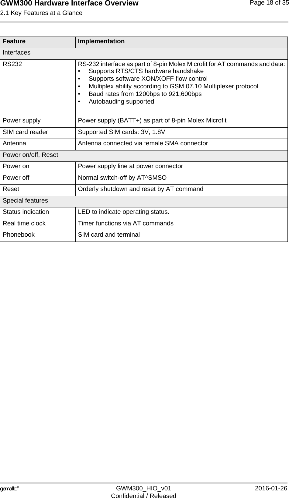
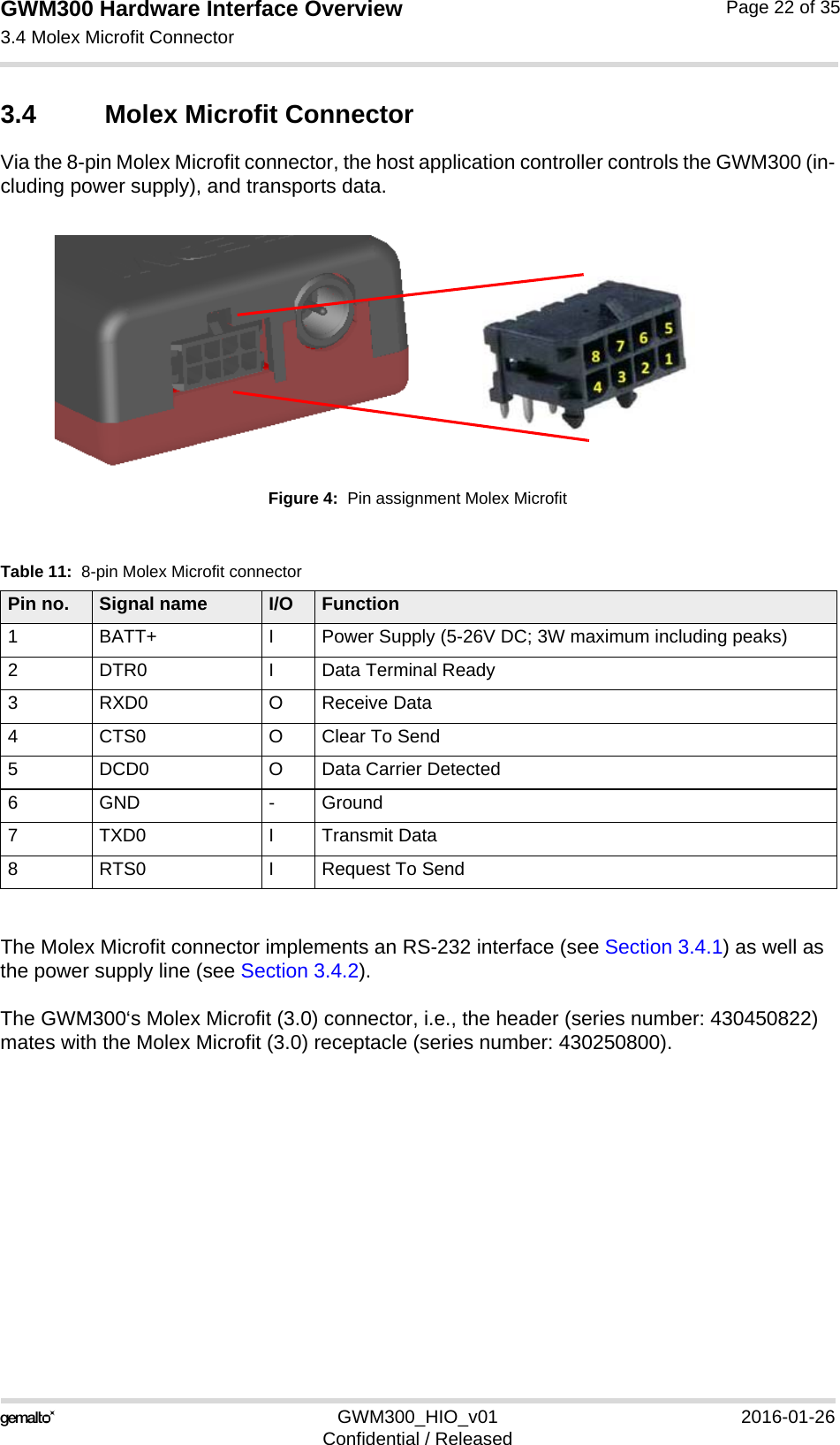
![GWM300 Hardware Interface Overview3.6 SIM Interface26GWM300_HIO_v01 2016-01-26Confidential / ReleasedPage 25 of 353.6 SIM Interface The SIM interface is intended for 1.8V and 3V SIM cards in accordance with GSM 11.12 Phase 2. The card holder is a five wire interface according to GSM 11.11. The SIM card holder is pro-tected by a rubber cover that has to be opened before a SIM can be inserted.Figure 5: SIM interfaceThe SIM - with the circuit side facing upwards - is inserted by gently pushing it into the SIM card holder until it snaps hold. It is now protected from accidental removal. The SIM can be removed from the card holder by using a flat object such as a screwdriver to carefully press the inserted SIM until it snaps out again.All signals of the SIM interface are protected from electrostatic discharge.Removing and inserting the SIM card during operation requires is not supported by GWM300. Note: No guarantee can be given, nor any liability accepted, if loss of data is encountered after removing the SIM card during operation. Also, no guarantee can be given for properly initializ-ing any SIM card that the user inserts after having removed a SIM card during operation. In this case, the application must restart the GWM300.3.7 Status LEDGWM300 has a green LED to indicate its operating status.Figure 6: Status LEDThe LED is enabled by default, but can be configured by AT command AT^SLED. For more information on the AT^SLED command please refer to [1]. SIM card readerStatus LED](https://usermanual.wiki/THALES-DIS-AlS-Deutschland/GWM300/User-Guide-2934837-Page-25.png)