THALES DIS AlS Deutschland PH8-P GSM/GPRS/UMTS/HSPA Module User Manual hio
Gemalto M2M GmbH GSM/GPRS/UMTS/HSPA Module hio
UserManual.wiki
>
THALES DIS AlS Deutschland
>
PH8-P User Manual
>
User Manual
Contents
1.
User Manual
2.
user manual
User Manual
Navigation menu
Upload a User Manual
Namespaces
Wiki Guide
HTML
PDF
Info
Views
User Manual
Discussion / Help
Navigation
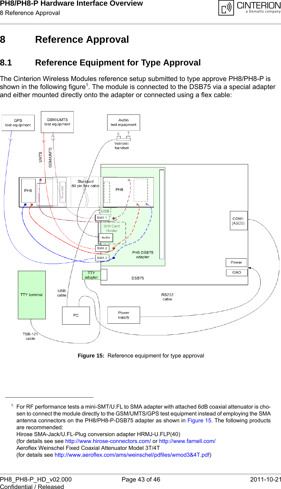
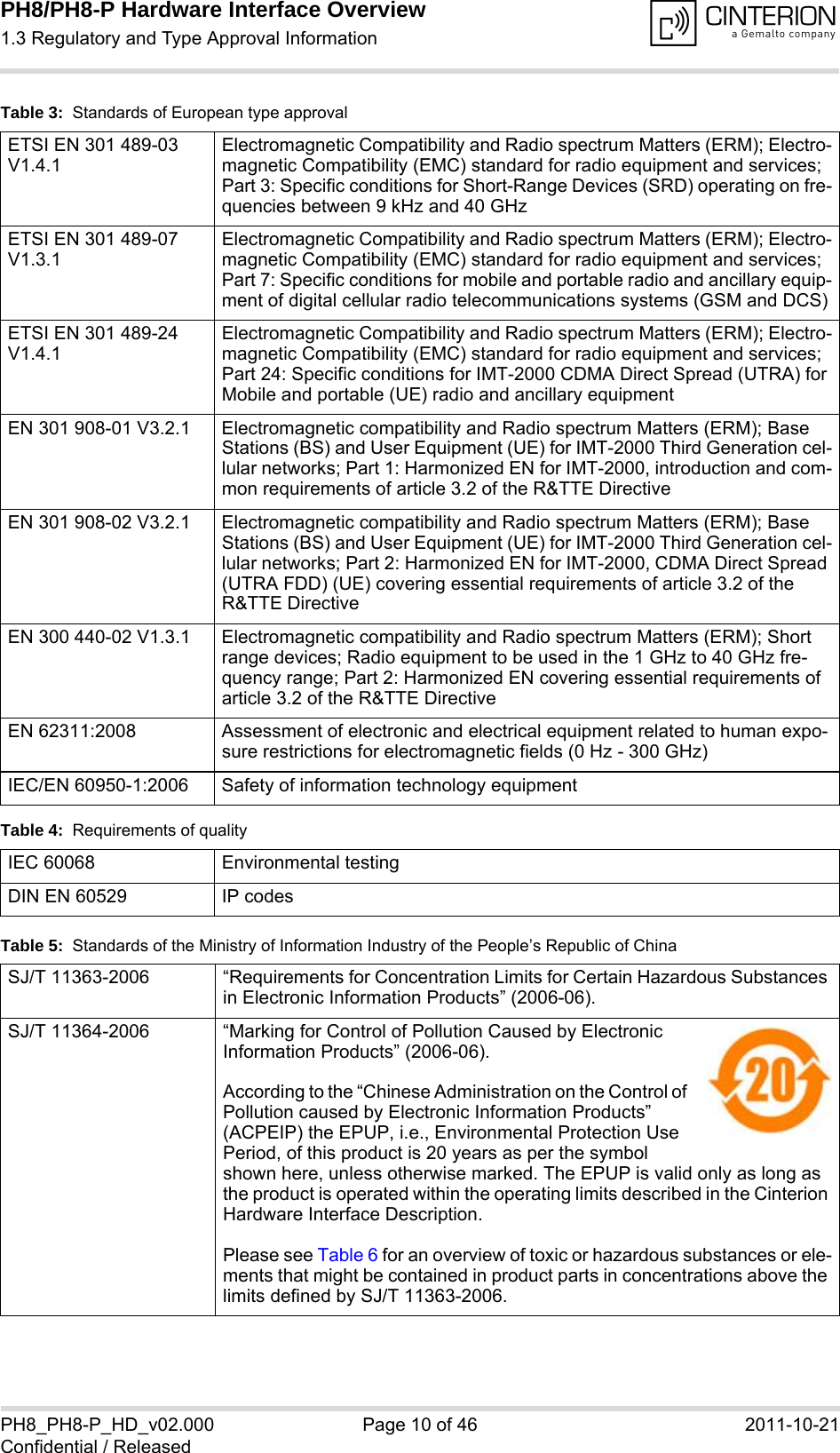
![PH8/PH8-P Hardware Interface Overview1 Introduction14PH8_PH8-P_HD_v02.000 Page 6 of 46 2011-10-21Confidential / Released1 IntroductionThe document1 describes the hardware of the PH8/PH8-P module, designed to connect to a cellular device application and the air interface. It helps you quickly retrieve interface specifica-tions, electrical and mechanical details and information on the requirements to be considered for integrating further components.1.1 Related Documents[1] PH8/PH8-P AT Command Set[2] PH8/PH8-P Release Notes[3] DSB75 Support Box - Evaluation Kit for Cinterion Wireless Modules1.2 Terms and Abbreviations1. The document is effective only if listed in the appropriate Release Notes as part of the technicaldocumentation delivered with your Cinterion Wireless Modules product.Abbreviation DescriptionAGPS Assisted GPSANSI American National Standards InstituteAMR Adaptive MultirateARP Antenna Reference PointB2B Board-to-board connectorBB BasebandBEP Bit Error ProbabilityBTS Base Transceiver StationCB or CBM Cell Broadcast MessageCE Conformité Européene (European Conformity)CS Coding SchemeCS Circuit SwitchedCSD Circuit Switched DataCTM Cellular Text ModemDAC Digital-to-Analog ConverterDCS Digital Cellular SystemDL DownloadDRX Discontinuous ReceptionDSB Development Support Board](https://usermanual.wiki/THALES-DIS-AlS-Deutschland/PH8-P.User-Manual/User-Guide-1565355-Page-6.png)
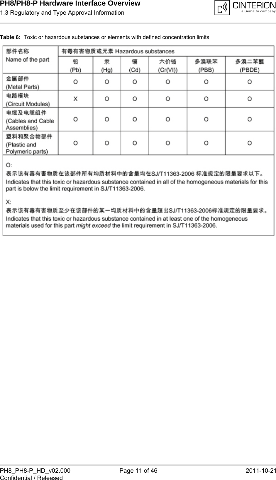
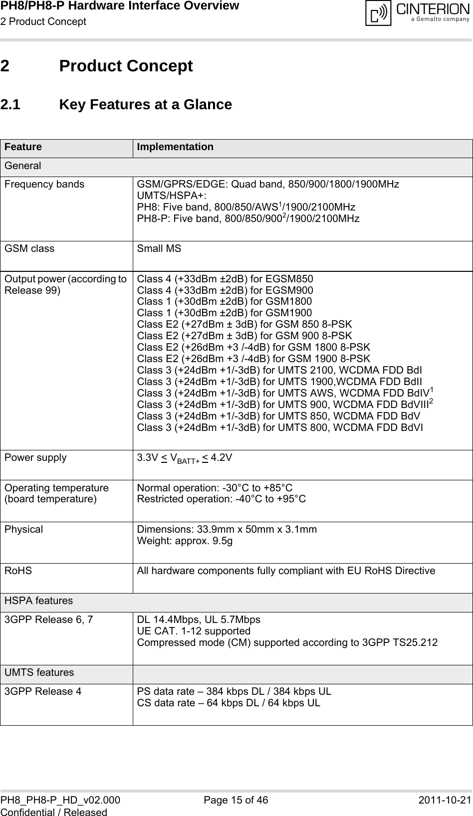
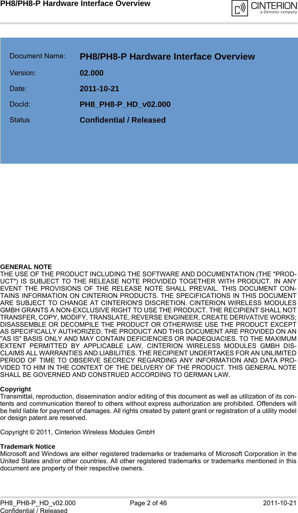
![PH8/PH8-P Hardware Interface Overview3.1 Operating Modes28PH8_PH8-P_HD_v02.000 Page 20 of 46 2011-10-21Confidential / Released3.1 Operating ModesThe table below briefly summarizes the various operating modes referred to in the following chapters.Table 7: Overview of operating modesMode FunctionNormal operationGSM / GPRS / UMTS / HSPA SLEEPPower saving set automatically when no call is in progress and the USB connection is suspended by host or not present and no active commu-nication via ASC0. GSM / GPRS / UMTS / HSPA IDLEPower saving disabled (see [1]: AT^SCFG "MEopMode/PwrSave",<PwrSaveMode>) or an USB connection not suspended, but no call in progress.GSM TALK/GSM DATAConnection between two subscribers is in progress. Power consump-tion depends on the GSM network coverage and several connection settings (e.g. DTX off/on, FR/EFR/HR, hopping sequences and antenna connection). The following applies when power is to be mea-sured in TALK_GSM mode: DTX off, FR and no frequency hopping.GPRS DATA GPRS data transfer in progress. Power consumption depends on net-work settings (e.g. power control level), uplink / downlink data rates and GPRS configuration (e.g. used multislot settings).EGPRS DATA EGPRS data transfer in progress. Power consumption depends on net-work settings (e.g. power control level), uplink / downlink data rates and EGPRS configuration (e.g. used multislot settings).UMTS TALK/UMTS DATAUMTS data transfer in progress. Power consumption depends on net-work settings (e.g. TPC Pattern) and data transfer rate.HSPA DATA HSPA data transfer in progress. Power consumption depends on net-work settings (e.g. TPC Pattern) and data transfer rate.Power DownNormal shutdown after sending the AT^SMSO command. Only a voltage regulator is active for powering the RTC. Software is not active. Interfaces are not accessible. Operating volt-age (connected to BATT+) remains applied.Airplane modeAirplane mode shuts down the radio part of the module, causes the module to log off from the GSM/GPRS network and disables all AT commands whose execution requires a radio connection.Airplane mode can be controlled by AT command (see [1]).](https://usermanual.wiki/THALES-DIS-AlS-Deutschland/PH8-P.User-Manual/User-Guide-1565355-Page-20.png)
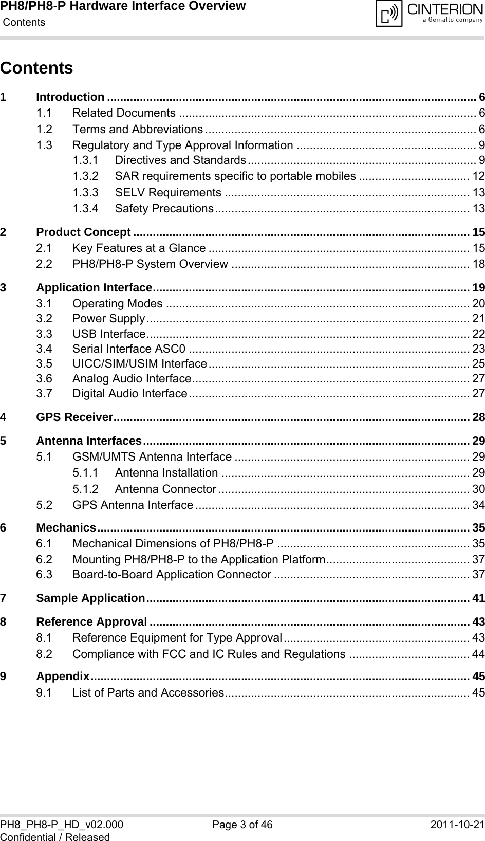
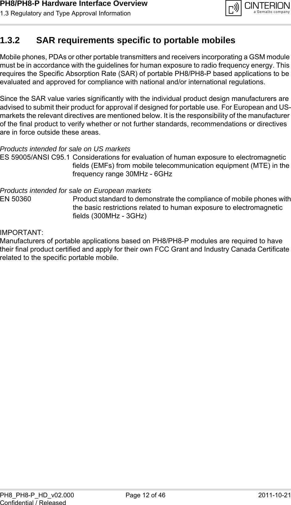
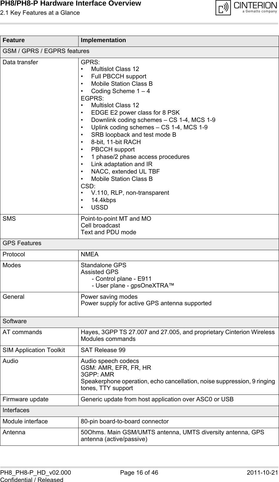
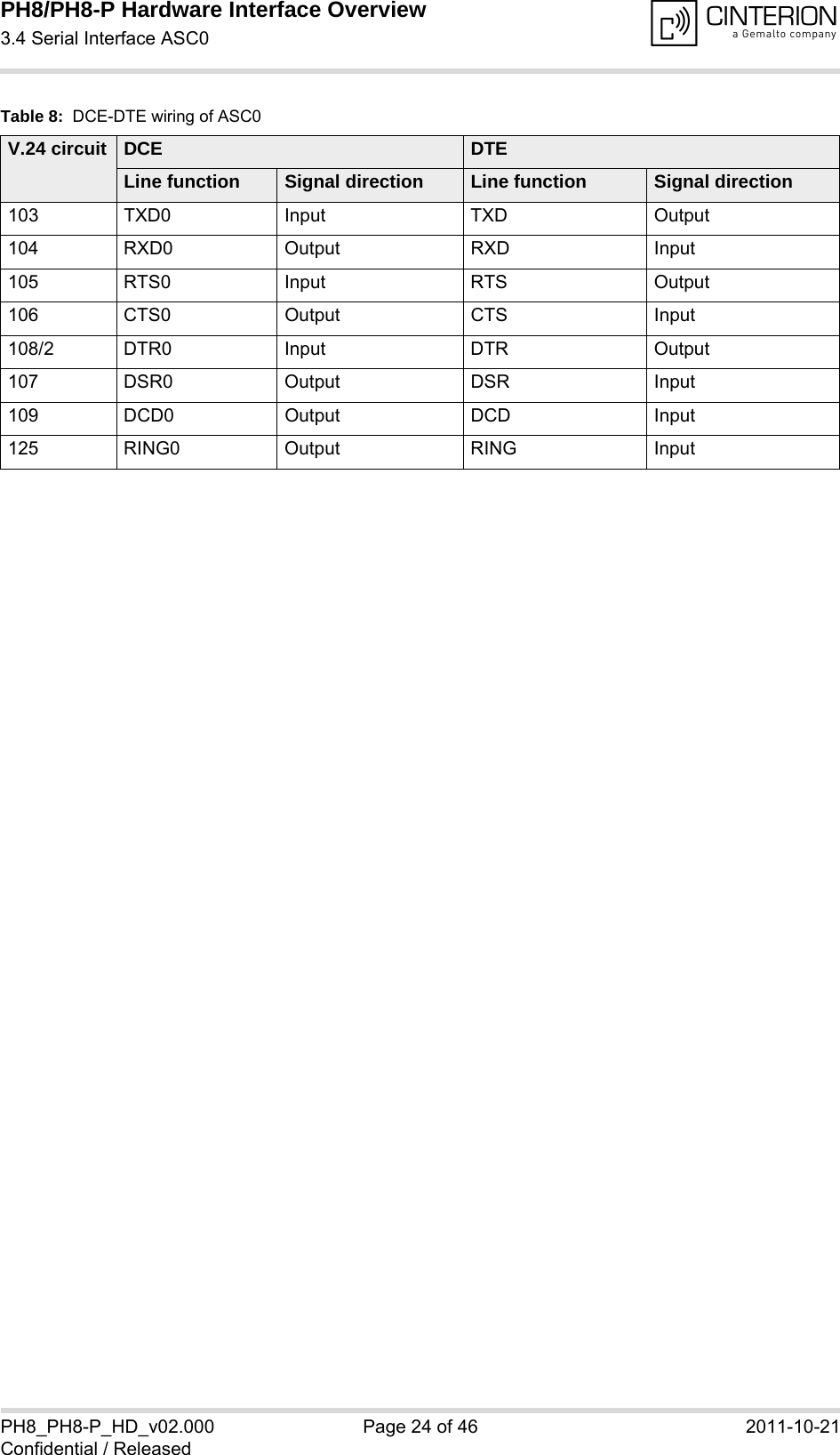
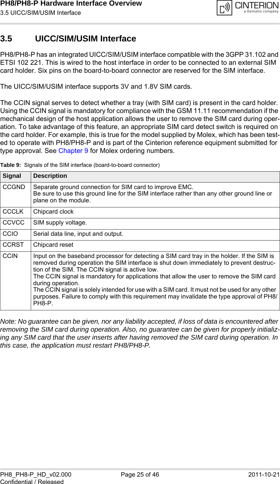
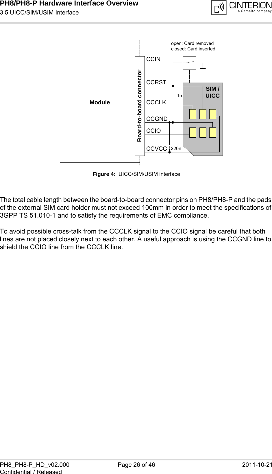
![PH8/PH8-P Hardware Interface Overview3.4 Serial Interface ASC028PH8_PH8-P_HD_v02.000 Page 23 of 46 2011-10-21Confidential / Released3.4 Serial Interface ASC0PH8/PH8-P offers an 8-wire unbalanced, asynchronous modem interface ASC0 conforming to ITU-T V.24 protocol DCE signalling. The electrical characteristics do not comply with ITU-T V.28. The significant levels are 0V (for low data bit or active state) and 1.8V (for high data bit or inactive state). PH8/PH8-P is designed for use as a DCE. Based on the conventions for DCE-DTE connections it communicates with the customer application (DTE) using the following signals:• Port TXD @ application sends data to the module’s TXD0 signal line• Port RXD @ application receives data from the module’s RXD0 signal lineFigure 3: Serial interface ASC0Features:• Includes the data lines TXD0 and RXD0, the status lines RTS0 and CTS0 and, in addition,the modem control lines DTR0, DSR0, DCD0 and RING0.• ASC0 is designed for controlling GSM/UMTS voice calls, transferring data and for control-ling the module with AT commands.• Full multiplexing capability allows the interface to be partitioned into virtual channels.• The RING0 signal serves to indicate incoming calls and other types of URCs (UnsolicitedResult Code). It can also be used to send pulses to the host application, for example towake up the application from power saving state. See [1] for details on how to configure theRING0 line by AT^SCFG.• Configured for 8 data bits, no parity and 1 stop bit. • ASC0 can be operated at fixed bit rates from 9600bps up to 921600bps.• Supports RTS0/CTS0 hardware flow control.• Wake up from SLEEP mode by RTS0 activation (high to low transition). Note. If the ASC0 serial interface is the application’s only interface, it is suggested to connect test points on the USB signal lines as a potential tracing possibility.](https://usermanual.wiki/THALES-DIS-AlS-Deutschland/PH8-P.User-Manual/User-Guide-1565355-Page-23.png)
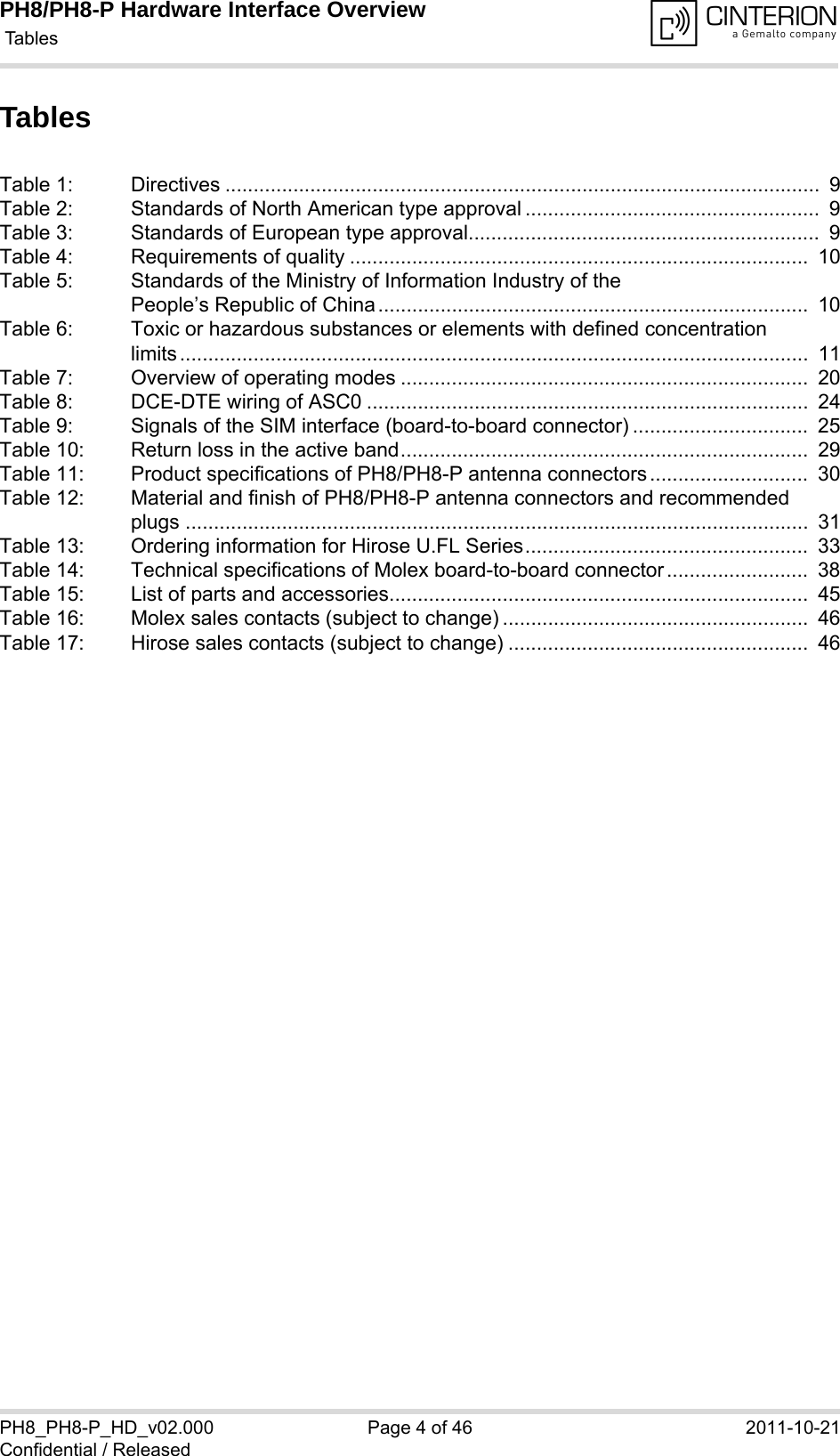
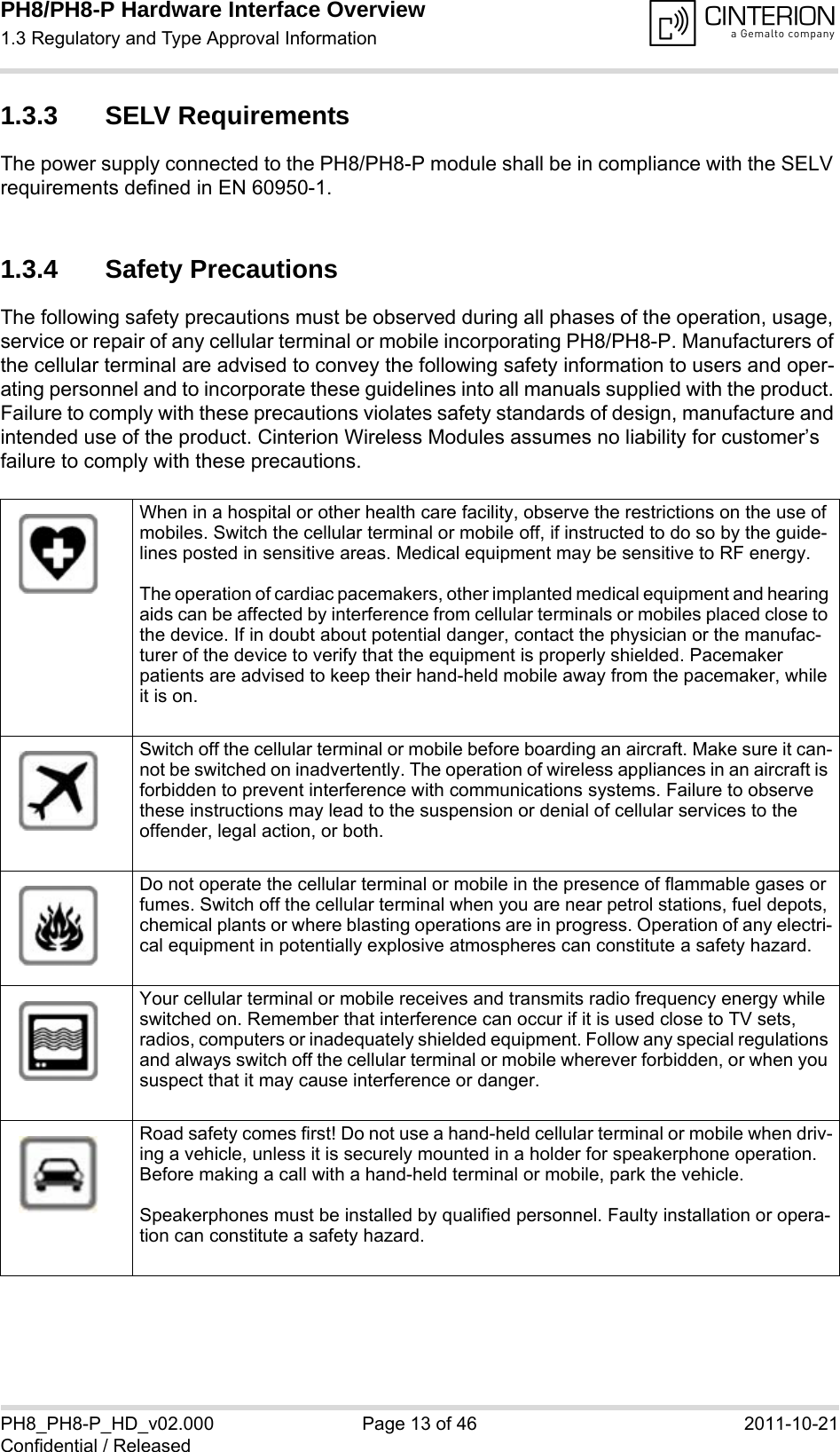
![PH8/PH8-P Hardware Interface Overview4 GPS Receiver28PH8_PH8-P_HD_v02.000 Page 28 of 46 2011-10-21Confidential / Released4 GPS ReceiverPH8/PH8-P integrates a GPS receiver that offers the full performance of GPS technology. The GPS receiver is able to continuously track all satellites in view, thus providing accurate satellite position data. The integrated GPS receiver supports the NMEA protocol via USB or ASC0 interface. NMEA is a combined electrical and data specification for communication between various (marine) electronic devices including GPS receivers. It has been defined and controlled by the US-based National Marine Electronics Association. For more information on the NMEA Standard please refer to http://www.nmea.org.Depending on the receiver’s knowledge of last position, current time and ephemeris data, the receiver’s startup time (i.e., TTFF = Time-To-First-Fix) may vary: If the receiver has no knowl-edge of its last position or time, a startup takes considerably longer than if the receiver has still knowledge of its last position, time and almanac or has still access to valid ephimeris data and the precise time. By default, the GPS receiver is switched off. It has to be switched on and configured using AT commands. For more information on how to control the GPS interface via the AT command AT^SGPSC see [1].](https://usermanual.wiki/THALES-DIS-AlS-Deutschland/PH8-P.User-Manual/User-Guide-1565355-Page-28.png)
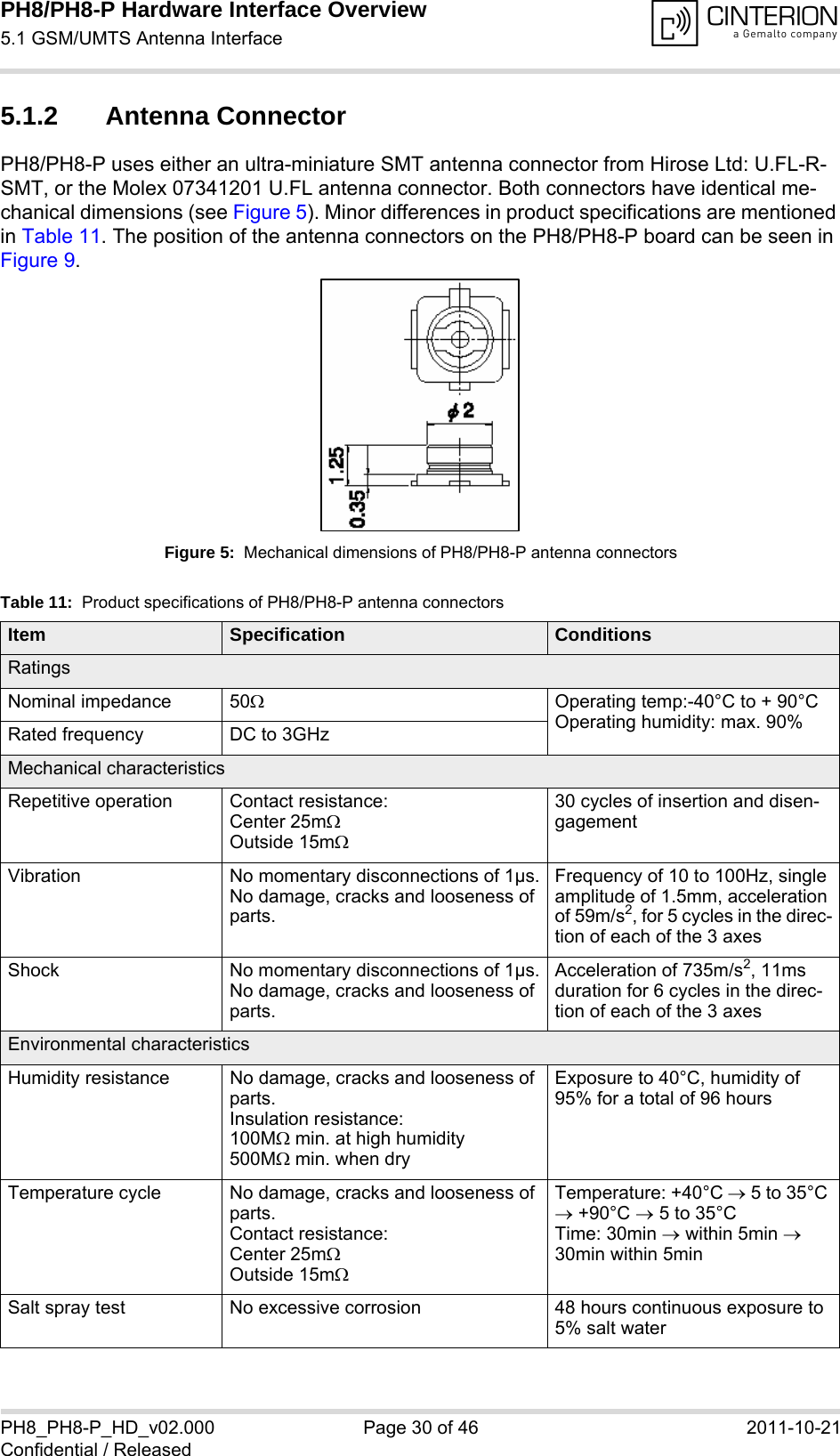
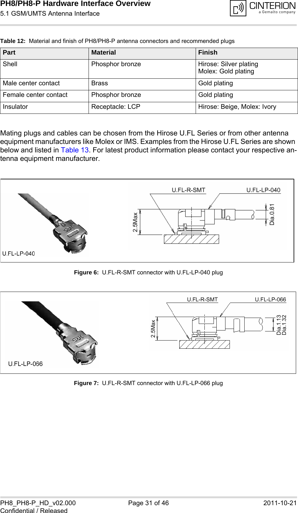
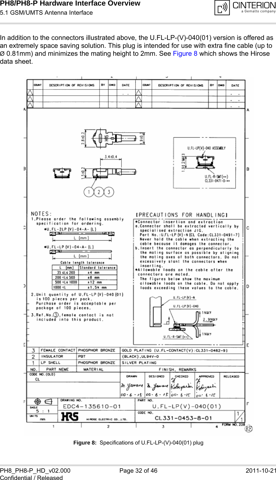
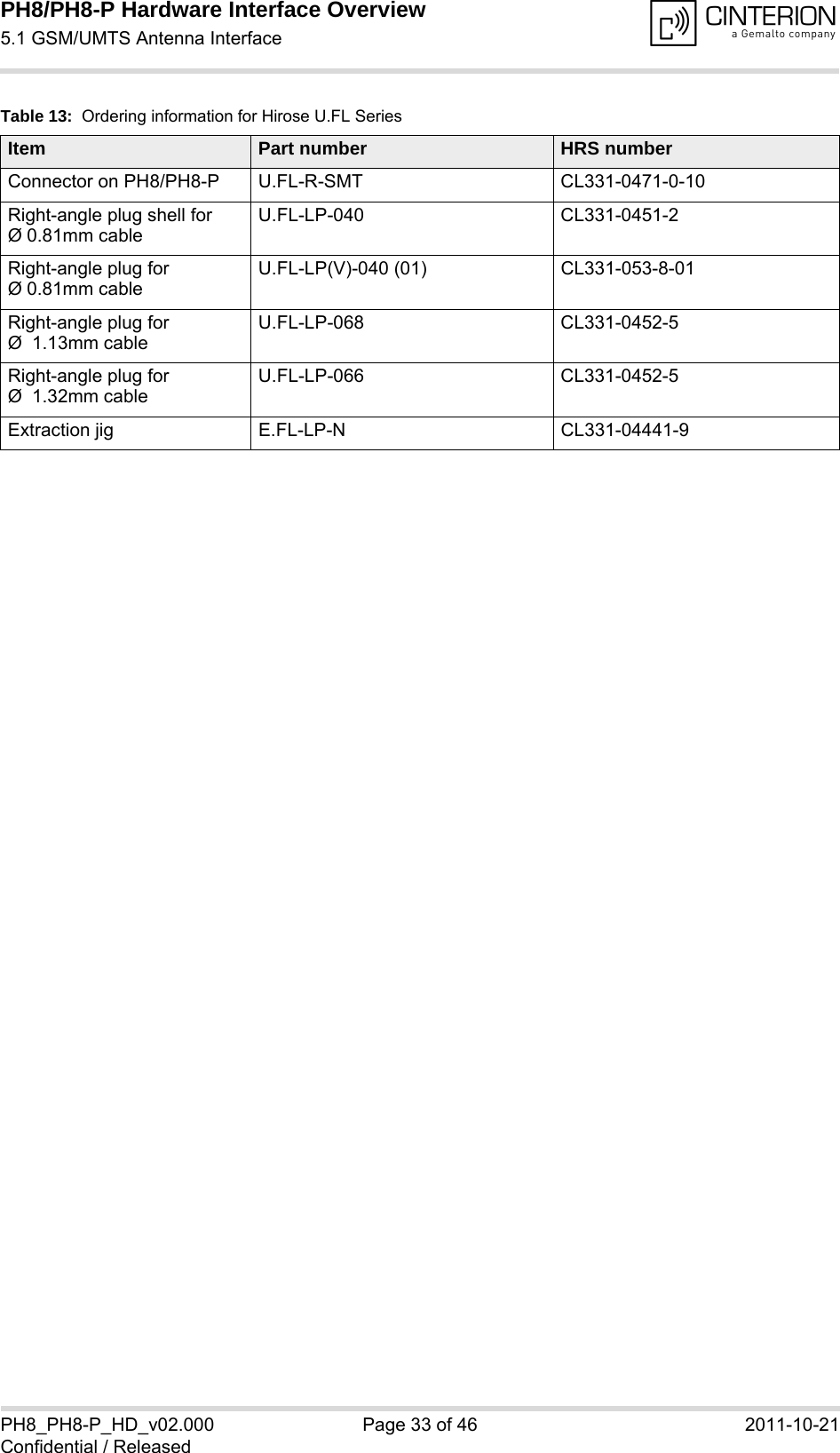
![PH8/PH8-P Hardware Interface Overview5 Antenna Interfaces34PH8_PH8-P_HD_v02.000 Page 29 of 46 2011-10-21Confidential / Released5 Antenna Interfaces5.1 GSM/UMTS Antenna InterfaceThe PH8/PH8-P GSM/UMTS antenna interface comprises a main GSM/UMTS antenna as well as an optional UMTS Rx diversity antenna to improve signal reliability and quality1. The inter-face has an impedance of 50Ω. PH8/PH8-P is capable of sustaining a total mismatch at the antenna interface without any damage, even when transmitting at maximum RF power.The external antenna must be matched properly to achieve best performance regarding radi-ated power, DC-power consumption, modulation accuracy and harmonic suppression. Match-ing networks are not included on the PH8/PH8-P PCB and should be placed in the host application, if the antenna does not have an impendance of 50Ω.Regarding the return loss PH8/PH8-P provides the following values in the active band:The connection of the antenna or other equipment must be decoupled from DC voltage. This is necessary because the antenna connector is DC coupled to ground via an inductor for ESD protection.5.1.1 Antenna InstallationThe U.FL antenna connector from Hirose/Molex of the main GSM/UMTS antenna has been chosen as antenna reference point (ARP) for the Cinterion Wireless Modules reference equip-ment submitted to type approve PH8/PH8-P. See Section 5.1.2 for details. All RF data specified throughout this manual is related to the ARP. The positions of the module’s antenna connectors can be seen in Figure 9.1. By delivery default the optional UMTS Rx diversity antenna is configured as available for the module. Toavoid negative side effects and performance degradation it is recommended to disable the diversity an-tenna path if - the host application does not support a diversity antenna- the host application includes a diversity antenna - but a 3G network simulator is used for developmentand performance tests.Please refer to [1] for details on how to configure antenna settings. Table 10: Return loss in the active bandState of module Return loss of module Recommended return loss of applicationReceive > 8dB > 12dBTransmit not applicable > 12dBIdle < 5dB not applicable](https://usermanual.wiki/THALES-DIS-AlS-Deutschland/PH8-P.User-Manual/User-Guide-1565355-Page-29.png)
![PH8/PH8-P Hardware Interface Overview5.2 GPS Antenna Interface34PH8_PH8-P_HD_v02.000 Page 34 of 46 2011-10-21Confidential / Released5.2 GPS Antenna InterfaceIn addition to the RF antenna interface PH8/PH8-P also has a GPS antenna interface. See Section 6.1 to find out where the GPS antenna connector is located. The GPS antenna instal-lation and connector are the same as for the RF antenna interface (see Section 5.1.1 and Sec-tion 5.1.2). It is possible to connect active or passive GPS antennas. In either case they must have 50 Ohm impedance. The simultaneous operation of GSM and GPS has been implemented. Active 3V GPS antennas can be supplied via the GPS antenna interface, if the supply voltage is switched on. This is done by AT command: AT^SGPSC="Power/Antenna" to configure the use of an active GPS antenna and AT^SGPSC="Engine" to start the GPS receiver (for com-mand details see [1]). The available current is limited to prevent short circuits.](https://usermanual.wiki/THALES-DIS-AlS-Deutschland/PH8-P.User-Manual/User-Guide-1565355-Page-34.png)