THERMADOR Dishwasher Manual L0501512
User Manual: THERMADOR THERMADOR Dishwasher Manual THERMADOR Dishwasher Owner's Manual, THERMADOR Dishwasher installation guides
Open the PDF directly: View PDF ![]() .
.
Page Count: 16
Thermador
Dishwasher Installation Manual
For Models DW44ZB, DW44ZW, DW44ZS, DW44ZP, DW44FI
Thermador
Installation Instructions
Table
IMPORTANT RNSTRUCTIONS ................ 1
Tools Needed ........................................... 2
Materials Needed ..................................... 2
Materials Supplied .................................... 3
Enclosure Preparation ............................. 4
Electrical Preparation ............................... 5
Plumbing Preparation ............................... 6
Dishwasher Preparation ........................... 7
of Contents
Placing the Dishwasher ........................... 9
Securing the Dishwasher ....................... 10
Drain Hose Connection .......................... 11
Hot Water Connection ............................ 12
Electrical Connection ............................. 12
Base and Toe Panel ............................... 13
Final instructions .................................... 13
Customer Service ................................... 14
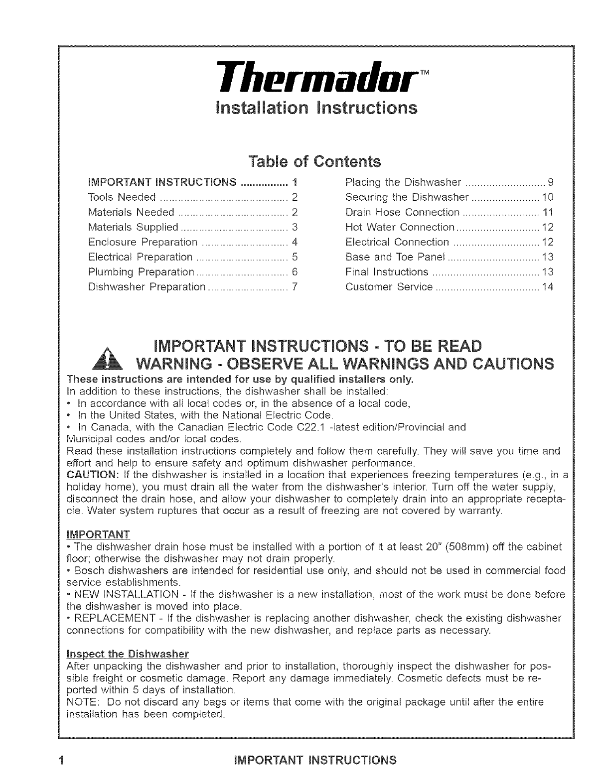
iMPORTANT iNSTRUCTiONS -TO BE READ
WARNING - OBSERVE ALL WARNINGS AND CAUTIONS
These instructions are intended for use by qualified installers only.
In addition to these instructions, the dishwasher shall be installed:
• In accordance with all local codes or, in the absence of a local code,
In the United States, with the National Electric Code.
In Canada, with the Canadian Electric Code C22.1 -latest edition/Provincial and
Municipal codes and/or local codes.
Read these installation instructions completely and follow them carefully. They will save you time and
effort and help to ensure safety and optimum dishwasher performance.
CAUTmON: If the dishwasher is installed in a location that experiences freezing temperatures (e.g., in a
holiday home), you must drain all the water from the dishwasher's interior. Turn off the water supply,
disconnect the drain hose, and allow your dishwasher to completely drain into an appropriate recepta-
cle. Water system ruptures that occur as a result of freezing are not covered by warranty.
IMPORTANT
• The dishwasher drain hose must be installed with a portion of it at least 20" (508mm) off the cabinet
flooK otherwise the dishwasher may not drain properly.
Bosch dishwashers are intended for residential use only, and should not be used in commercial food
service establishments.
• NEW INSTALLATION - If the dishwasher is a new installation, most of the work must be done before
the dishwasher is moved into place.
REPLACEMENT - If the dishwasher is replacing another dishwasher, check the existing dishwasher
connections for compatibility with the new dishwasher, and replace parts as necessary.
Inspect the Dishwasher
After unpacking the dishwasher and prior to installation, thoroughly inspect the dishwasher for pos-
sible freight or cosmetic damage. Report any damage immediately. Cosmetic defects must be re-
ported within 5 days of installation.
NOTE: Do not discard any bags or items that come with the original package until after the entire
installation has been completed.
1 iMPORTANT iNSTRUCTiONS
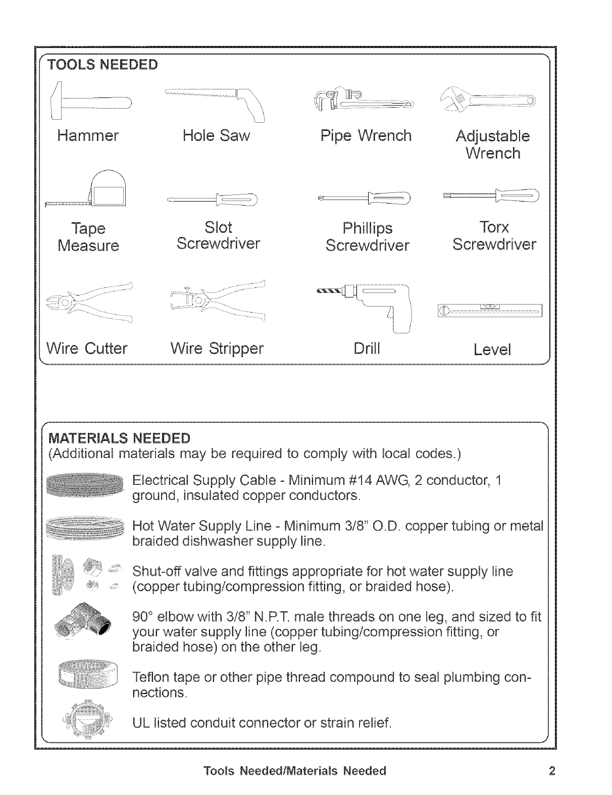
TOOLS NEEDED
Hammer Hole Saw Pipe Wrench Adjustable
Wrench
Tape Slot Phillips Torx
Measure Screwdriver Screwdriver Screwdriver
Wire Cutter Wire Stripper Drill Level
MATERmALS NEEDED
(Additional materials may be required to comply with local codes.)
Electrical Supply Cable - Minimum #14 AWG, 2 conductor, 1
ground, insulated copper conductors.
Hot Water Supply Line -Minimum 3/8" O.D. copper tubing or metal
braided dishwasher supply line.
Shut-off valve and fittings appropriate for hot water supply line
(copper tubing/compression fitting, or braided hose).
90° elbow with 3/8" N.P.T. maMethreads on one leg, and sized to fit
your water supply line (copper tubing/compression fitting, or
braided hose) on the other leg.
Teflon tape or other pipe thread compound to seal plumbing con-
nections.
Too_s NeededtMateria_s Needed 2
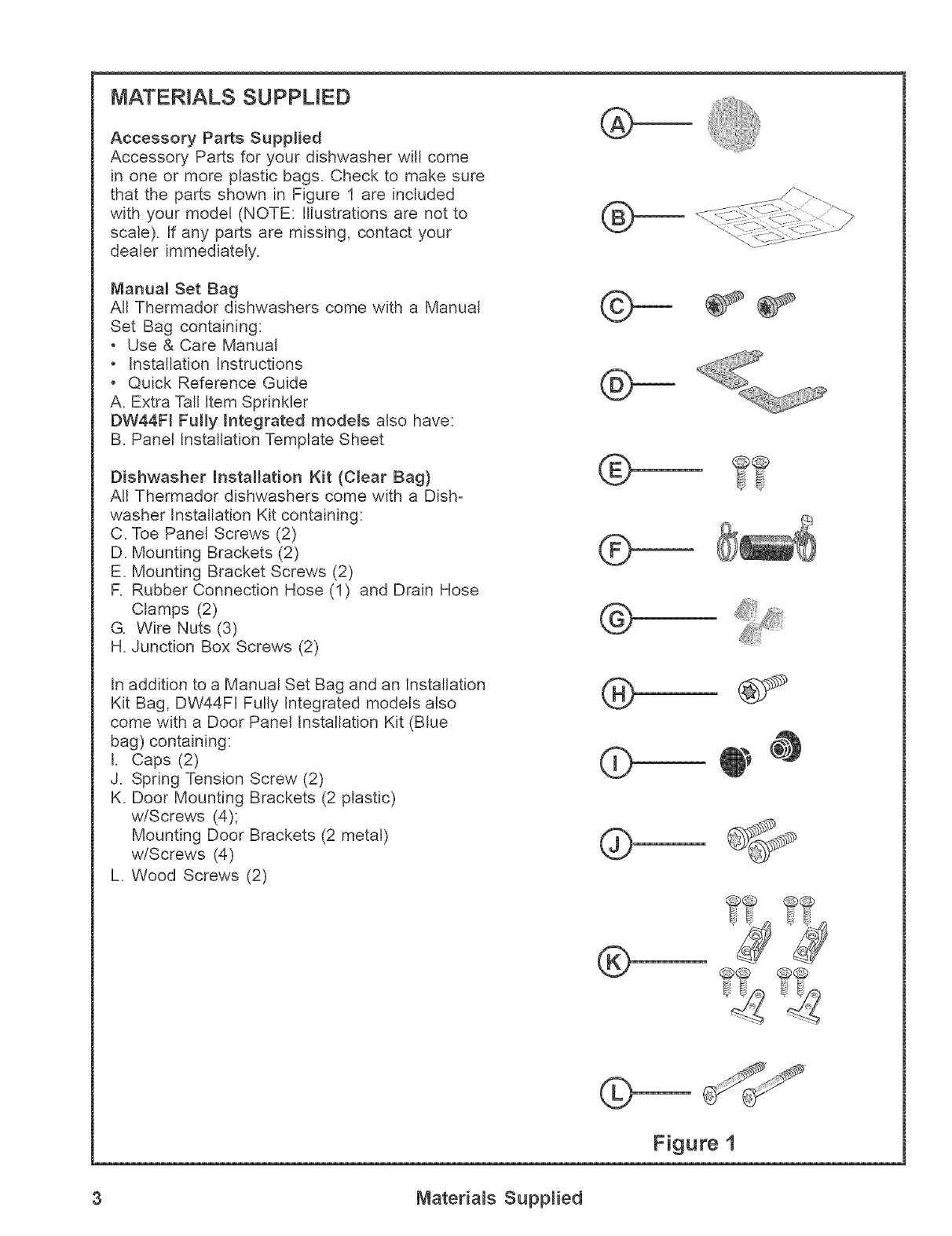
MATERIALS SUPPLIED
Accessory Parts Supplied
Accessory Parts for your dishwasher will come
in one or more plastic bags. Check to make sure
that the parts shown in Figure 1 are included
with your model (NOTE: Illustrations are not to
scale). If any parts are missing, contact your
dealer immediateJy.
Manual Set Bag
All Thermador dishwashers come with a Manual
Set Bag containing:
Use & Care Manual
• Installation Instructions
• Quick Reference Guide
A. Extra Tall Item Sprinkler
DW44FI Fully Integrated models also have:
B. Panel Installation Template Sheet
Dishwasher installation Kit (Clear Bag)
All Thermador dishwashers come with a Dish-
washer Installation Kit containing:
C. Toe Panel Screws (2)
D. Mounting Brackets (2)
E. Mounting Bracket Screws (2)
R Rubber Connection Hose (1) and Drain Hose
Clamps (2)
G. Wire Nuts (3)
H. Junction Box Screws (2)
In addition to a Manual Set Bag and an Installation
Kit Bag, DW44FI Fully Integrated models also
come with a Door Panel Installation Kit (Blue
bag) containing:
L Caps (2)
J. Spring Tension Screw (2)
K. Door Mounting Brackets (2 plastic)
w/Screws (4);
Mounting Door Brackets (2 metal)
w/Screws (4)
L. Wood Screws (2)
®
®
®
@
@
@
,
®
©
Figure 1
3 Materials Supplied
ENCLOSURE PREPARATION r -,
WARNING: INJURY HAZARD - Seri-
ous injury could result if cabinet work is
performed by unqualified persons. Only
qualified carpenters or cabinetmakers
should perform cabinet work.
NOTE: Thermador dishwashers are de-
signed to be enclosed on the top and both
sides by standard residential kitchen
cabinetry.
Select a location as close to the sink as
possible for easy access to water supply and
drain lines.
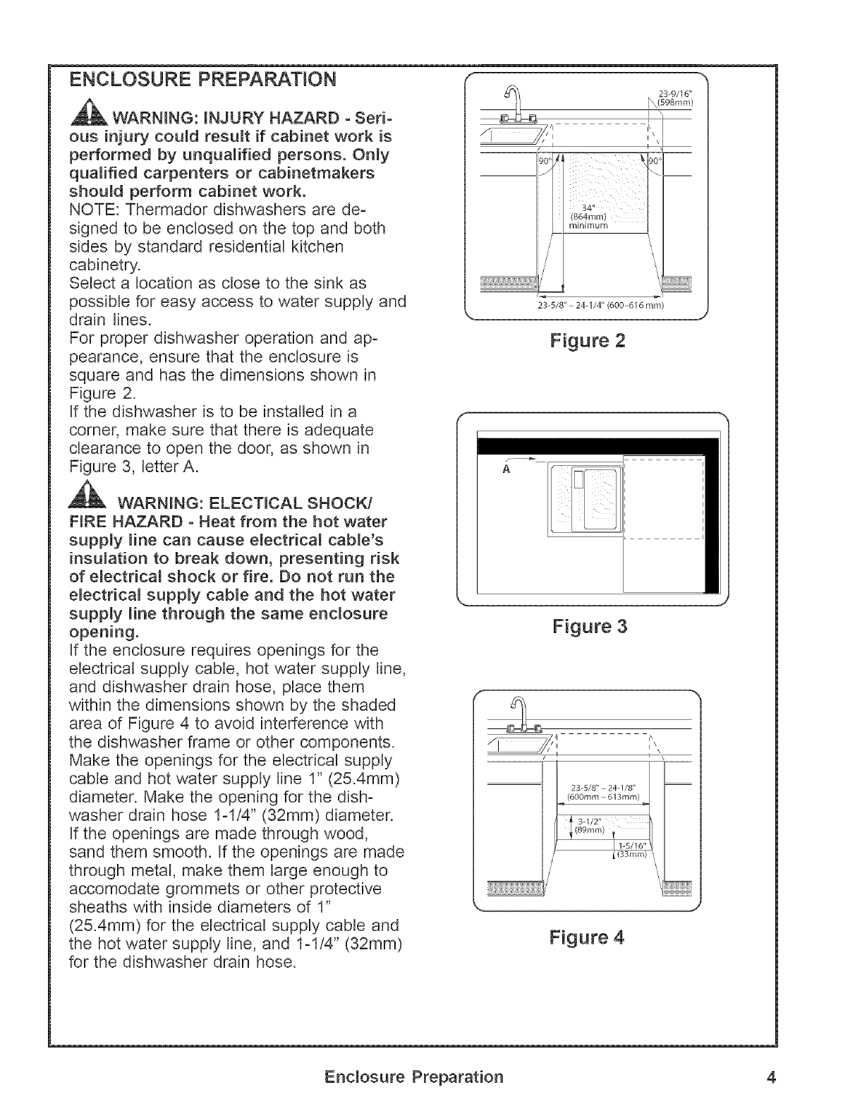
For proper dishwasher operation and ap-
pearance, ensure that the enclosure is
square and has the dimensions shown in
Figure 2.
If the dishwasher is to be installed in a
corner, make sure that there is adequate
clearance to open the door, as shown in
Figure 3, letter A.
WARNING: ELECTICAL SHOCK/
FIRE HAZARD -Heat from the hot water
supply line can cause electrical cable's
insulation to break down, presenting risk
of electrical shock or fire. Do not run the
electrical supply cable and the hot water
supply line through the same enclosure
opening.
If the enclosure requires openings for the
electrical supply cable, hot water supply line,
and dishwasher drain hose, place them
within the dimensions shown by the shaded
area of Figure 4 to avoid interference with
the dishwasher frame or other components.
Make the openings for the electrical supply
cable and hot water supply line 1" (25.4mm)
diameter. Make the opening for the dish-
washer drain hose 1-1/4" (32mm) diameter.
If the openings are made through wood,
sand them smooth. If the openings are made
through metal, make them large enough to
accomodate grommets or other protective
sheaths with inside diameters of 1"
(25.4mm) for the electrical supply cable and
the hot water supply line, and 1ol/4" (32mm)
for the dishwasher drain hose.
I '
34"
(864mm)
minimum
///'
234/8" 24-[/4"(600-616 mm)
J
Figure 2
Figure 3
i\
I\\
I\
/IIii'
Figure 4
Enclosure Preparation 4
ELECTRICAL PREPARATION
WARNING: ELECTRICAL SHOCK
HAZARD - Working on an energized
circuit could result in serious injury or
death. Only qualified electricians should
perform electrical work. Do not attempt
any work on the dishwasher electric
supply circuit until you are certain the
circuit is de-energized.
WARNING: FIRE HAZARD -
Improper electrical work can cause fire.
Only qualified electricians should per-
form electrical work.
Electrical Supply
The customer has the responsibility of
ensuring that the dishwasher electrical
insta[Jation is in compliance with aJJna-
tional and local electrical codes and ordi-
nances. The dishwasher is designed for an
electrical supply of 120V, 60 Hz, AC, con-
nected to a dishwasher-dedicated, properly
grounded electrical circuit with a fuse or
breaker rated for 15 amps. If the dish-
washer is connected with a food disposer, a
20 amp (and no higher) fuse or circuit
breaker may be used. Electrical supply
conductors shall be a minimum #14 AWG
copper wire.
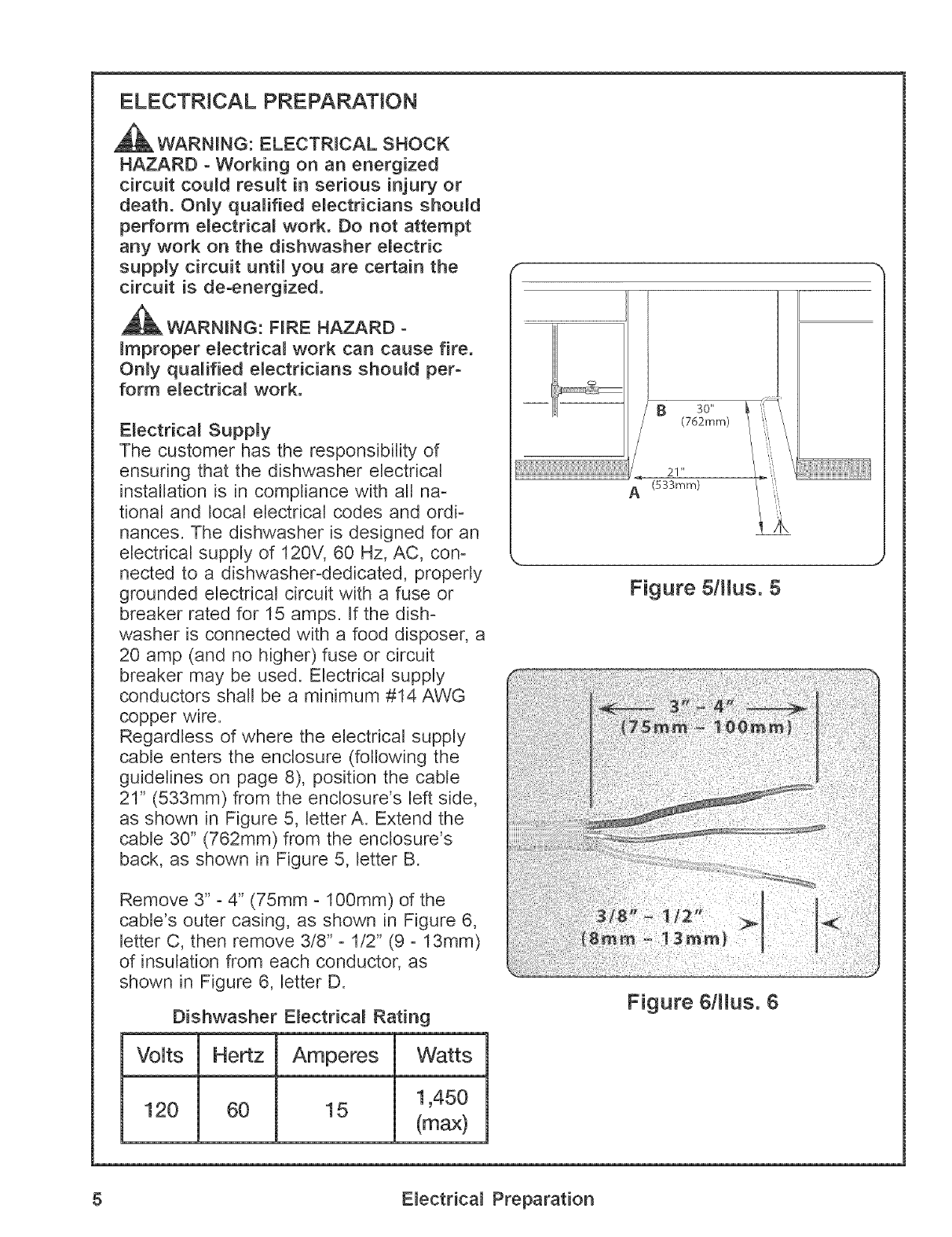
Regardless of where the electrical supply
cable enters the enclosure (following the
guidelines on page 8), position the cable
21" (533mm) from the enclosure's left side,
as shown in Figure 5, letter A. Extend the
cable 30" (762mm) from the enclosure's
back, as shown in Figure 5, letter B.
Remove 3" -4" (75mm o100mm) of the
cable's outer casing, as shown in Figure 6,
letter C, then remove 3/8"o 1/2" (9 -13mm)
of insulation from each conductor, as
shown in Figure 6, letter D.
Dishwasher Electrical Rating
Volts Hertz Amperes Watts
120 60 15 1,450
(max)
30"
(762mm)
21"
(533mm)
ii
Figure 5/tJus. 5
Figure 6/lJus. 6
5 Electrical Preparation
PLUMBING PREPARATION
WARNING: SCALD HAZARD -
Serious injury could result if work is
performed on a charged hot water _ine.
Only qualified plumbers should perform
plumbing work. Do not attempt any work
on the dishwasher hot water supply
plumbing until you are certain the hot
water supply is shut off.
CAUTION: Temperatures required for sol-
dering and sweating will damage the
dishwasher's base and water inlet valve. If
plumbing lines are to be soldered or
sweated, keep the heat source at least 6
inches (152.4 mm) away from the
dishwasher's base and water inlet valve.
Hot Water Supply
Thermador recommends that the hot water
heater be set to deliver approximately
120 ° F (49 ° C) water to the dishwasher.
Water that is too hot can cause some deter-
gents to loose effectiveness. Lower water
temperatures will increase run time.
The hot water supply pressure must be
between 5 - 120 psi (0.3 - 8.27 bars).
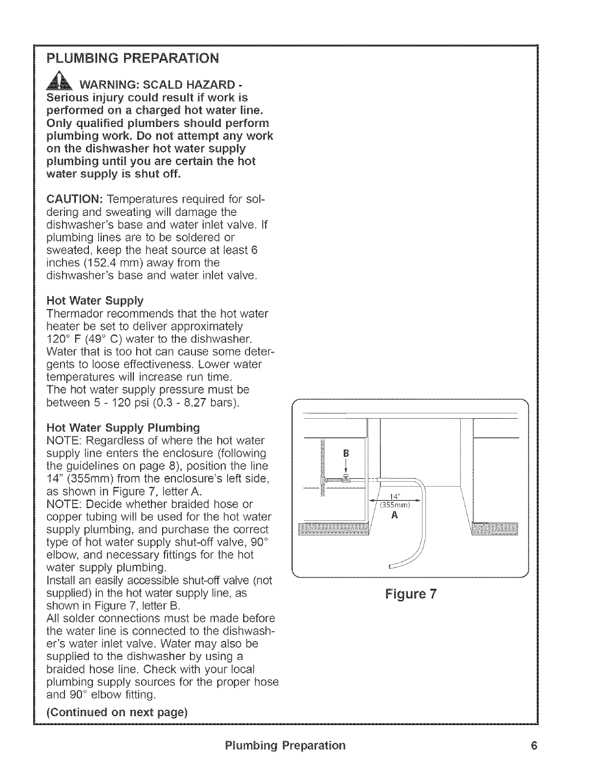
Hot Water Supply Plumbing
NOTE: Regardless of where the hot water
supply line enters the enclosure (following
the guidelines on page 8), position the line
14" (355mm) from the enclosure's left side,
as shown in Figure 7, letter A.
NOTE: Decide whether braided hose or
copper tubing will be used for the hot water
supply plumbing, and purchase the correct
type of hot water supply shut-off valve, 90 °
elbow, and necessary fittings for the hot
water supply plumbing.
Install an easily accessible shut-off valve (not
supplied) in the hot water supply line, as
shown in Figure 7, letter B.
All solder connections must be made before
the water line is connected to the dishwash-
er's water inlet valve. Water may also be
supplied to the dishwasher by using a
braided hose line. Check with your local
plumbing supply sources for the proper hose
and 90 ° elbow fitting.
(Continued on next page)
(355mm)
A
_J
Figure 7
Plumbing Preparation 6
PLUMBING PREPARATION
(continued)
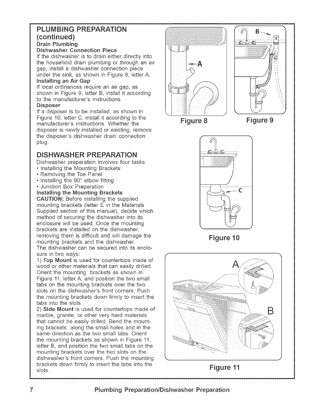
Brain P_umbing
Dishwasher Connection Piece
If the dishwasher is to drain either directly into
the household drain plumbing or through an air
gap, install a dishwasher connection piece
under the sink, as shown in Figure 8, letter A.
Installing an Air Gap
If local ordinances require an air gap, as
shown in Figure 9, letter B, install it according
to the manufacturer's instructions.
Disposer
If a disposer is to be installed, as shown in
Figure 10, letter C, install it according to the
manufacturer's instructions. Whether the
disposer is newly installed or existing, remove
the disposer's dishwasher drain connection
plug.
DISHWASHER PREPARATION
Dishwasher preparation involves four tasks:
Installing the Mounting Brackets
• Removing the Toe Panel
• Installing the 90 ° elbow fitting
• Junction Box Preparation
mnstalling the Mounting Brackets
CAUTION: Before installing the supplied
mounting brackets (letter E in the Materials
Supplied section of this manual), decide which
method of securing the dishwasher into its
enclosure will be used. Once the mounting
brackets are installed on the dishwasher,
removing them is difficult and will damage the
mounting brackets and the dishwasher.
The dishwasher can be secured into its enclo-
sure in two ways:
1) Top Mount is used for countertops made of
wood or other materials that can easily drilled.
Orient the mounting brackets as shown in
Figure 11, letter A, and position the two small
tabs on the mounting brackets over the two
slots on the dishwasher's front corners. Push
the mounting brackets down firmly to insert the
tabs into the slots.
2) Side Mount is used for countertops made of
marble, granite, or other very hard materials
that cannot be easily drilled. Bend the mount-
ing brackets along the small holes and in the
same direction as the two small tabs. Orient
the mounting brackets as shown in Figure 11,
letter B, and position the two small tabs on the
mounting brackets over the two slots on the
dishwasher's front corners. Push the mounting
brackets down firmly to insert the tabs into the
slots.
Figure 8 Figure 9
Figure 10
Figure 11
7 P_umbing Preparation/Dishwasher Preparation
DISHWASHER PREPARATION
(continued)
Removing the Toe Pane[
Regular Toe Pane[
The toe pane[ is loosely attached with tape.
Remove the tape and pull the toe panel
away from the dishwasher. Set the toe panel
aside. It will be reinstalled later.
Installing the 90 ° Elbow Fitting
NOTE: The 90 ° elbow fitting is not supplied
with the dishwasher, and must be purchased
separately, tf the dishwasher's hot water
supply line is to be copper tubing, make
certain the elbow has a compression fitting.
Apply Teflon tape or other pipe sealant to all
threaded connectors.
Orient the hot water supply connection leg
of the elbow toward the channel opening in
the dishwasher base.
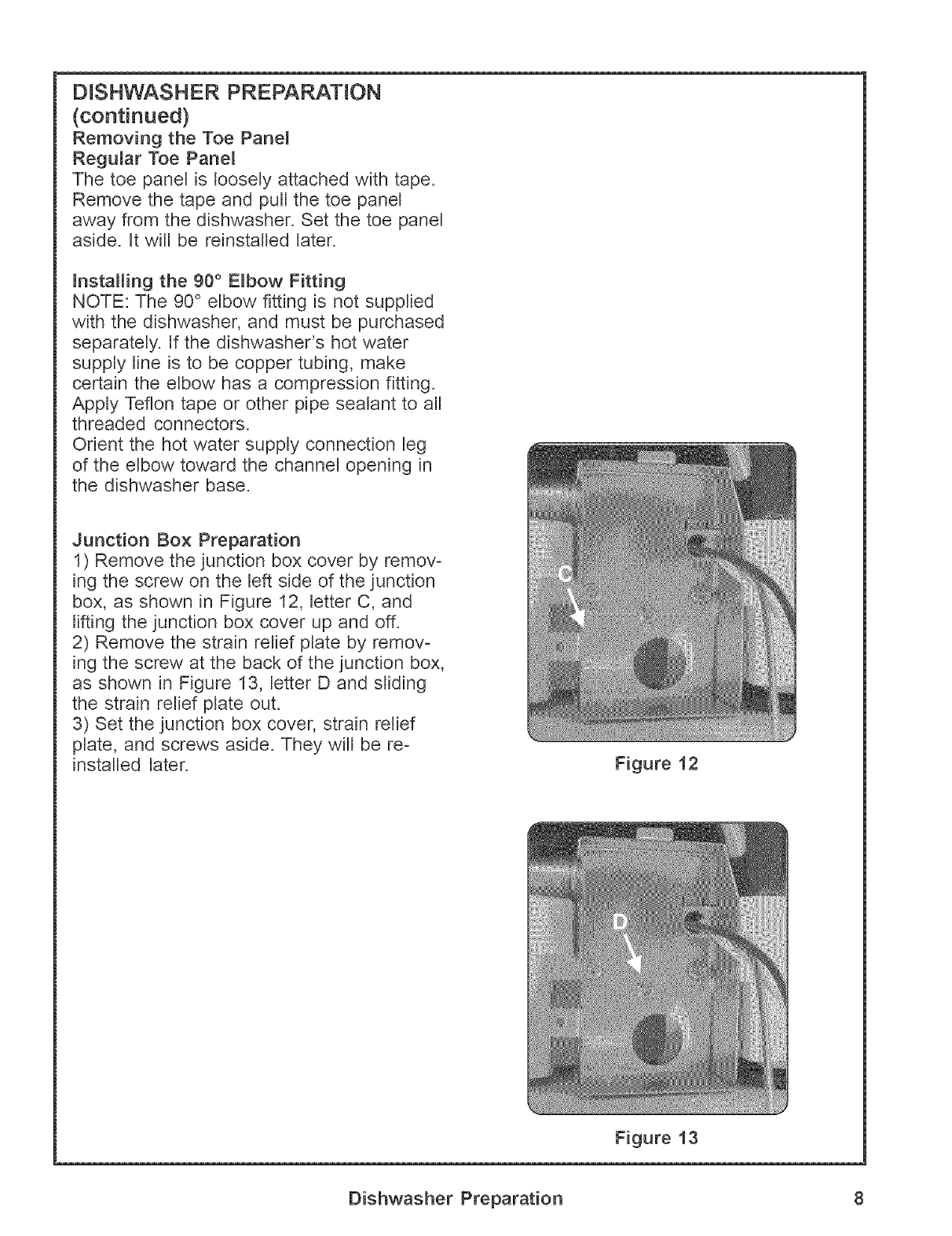
Junction Box Preparation
1) Remove the junction box cover by remov-
ing the screw on the left side of the junction
box, as shown in Figure 12, letter C, and
lifting the junction box cover up and off.
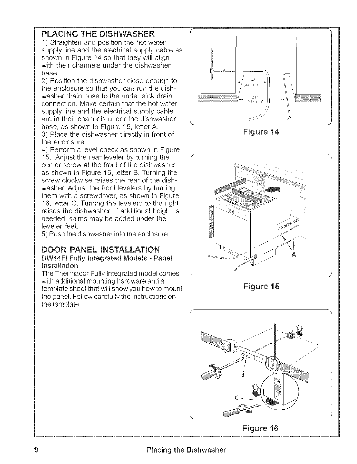
2) Remove the strain relief plate by remov-
ing the screw at the back of the junction box,
as shown in Figure 13, letter D and sliding
the strain relief plate out.
3) Set the junction box cover, strain relief
plate, and screws aside. They will be re-
installed later. Figure 12
Figure 13
Dishwasher Preparation 8
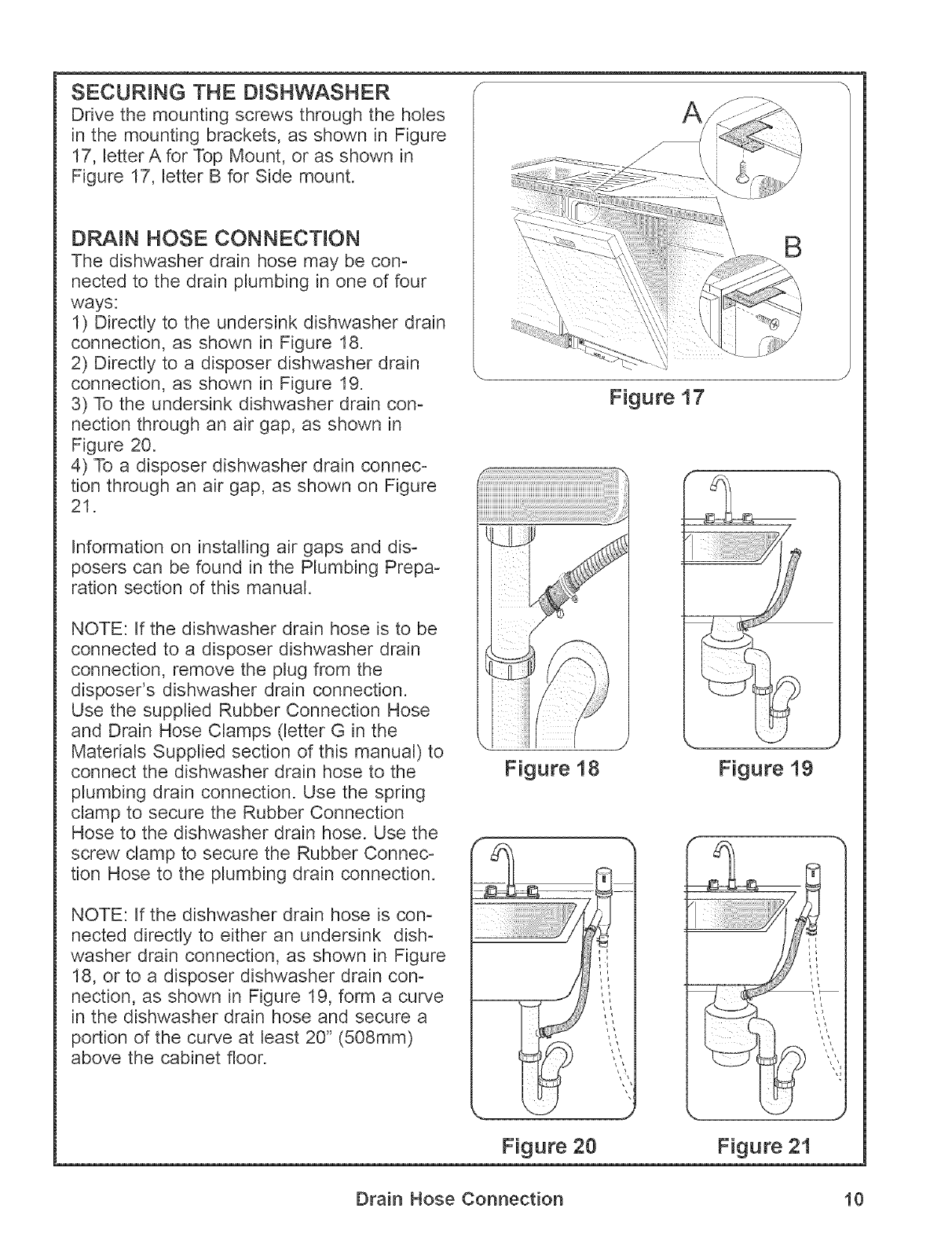
PLACING THE DISHWASHER
1) Straighten and position the hot water
supply line and the electrical supply cable as
shown in Figure 14 so that they will align
with their channels under the dishwasher
base.
2) Position the dishwasher close enough to
the enclosure so that you can run the dish°
washer drain hose to the under sink drain
connection. Make certain that the hot water
supply line and the electrical supply cable
are in their channels under the dishwasher
base, as shown in Figure 15, letterA.
3) Place the dishwasher directJyin front of
the enclosure.
4) Perform a level check as shown in Figure
15. Adjust the rear leveler by turning the
center screw at the front of the dishwasher,
as shown in Figure 16, letter B. Turning the
screw cJockwiseraises the rear of the dish-
washer. Adjust the front levelers by turning
them with a screwdriver, as shown in Figure
16, letter C. Turning the levelers to the right
raises the dishwasher. If additional height is
needed, shims may be added under the
leveler feet.
5) Pushthe dishwasher intothe enclosure.
DOOR PANEL INSTALLATION
DW44F_ Fummy_ntegrated Mode_s oPane_
_nstaHation
The Thermador Fully Integrated model comes
with additional mounting hardware and a
template sheet that will show you how to mount
the panel. Follow, carefully the instructions on
the template.
_T_
Figure 14
Figure 1,5
Figure 1{}
9 P_acing the Dishwasher
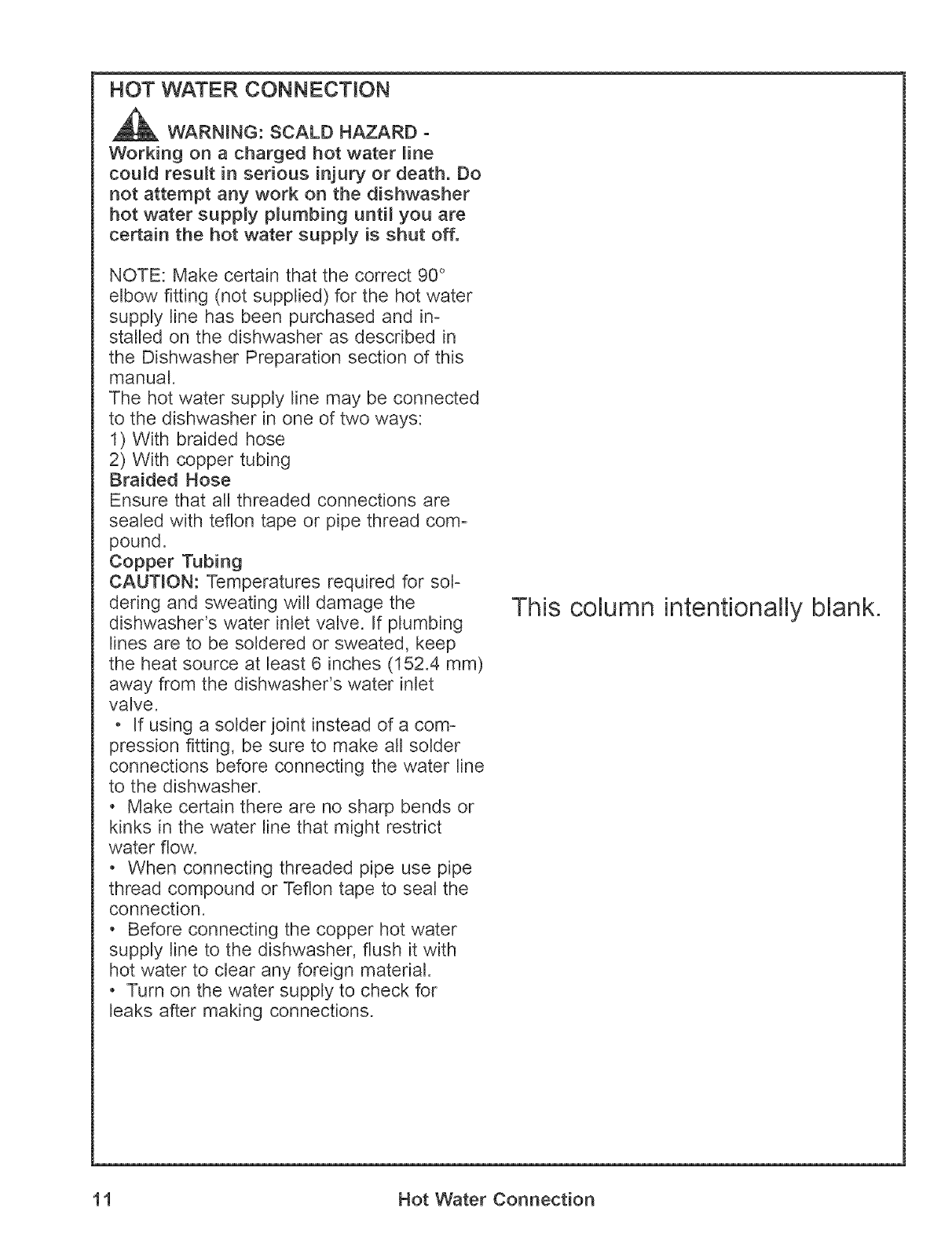
SECURING THE DISHWASHER
Drive the mounting screws through the holes
in the mounting brackets, as shown in Figure
17, letter A for Top Mount, or as shown in
Figure 17, Letter B for Side mount.
DP_IN HOSE CONNECTION
The dishwasher drain hose may be con-
nected to the drain plumbing in one of four
ways:
1) Directly to the undersink dishwasher drain
connection, as shown in Figure 18.
2) Directly to a disposer dishwasher drain
connection, as shown in Figure 19.
3) To the undersink dishwasher drain con-
nection through an air gap, as shown in
Figure 20.
4) To a disposer dishwasher drain connec-
tion through an air gap, as shown on Figure
21.
Information on installing air gaps and dis-
posers can be found in the Plumbing Prepa-
ration section of this manual.
NOTE: If the dishwasher drain hose is to be
connected to a disposer dishwasher drain
connection, remove the plug from the
disposer's dishwasher drain connection.
Use the supplied Rubber Connection Hose
and Drain Hose Clamps (letter G in the
Materials Supplied section of this manual) to
connect the dishwasher drain hose to the
plumbing drain connection. Use the spring
clamp to secure the Rubber Connection
Hose to the dishwasher drain hose. Use the
screw clamp to secure the Rubber Connec-
tion Hose to the plumbing drain connection.
NOTE: If the dishwasher drain hose is con-
nected directly to either an undersink dish-
washer drain connection, as shown in Figure
18, or to a disposer dishwasher drain con°
nection, as shown in Figure 19, form a curve
in the dishwasher drain hose and secure a
portion of the curve at least 20" (508mm)
above the cabinet floor.
Figure 18
B
Figure 17
Figure 19
Figure 20 Figure 21
Drain Hose Connection 10
HOT WATER CONNECTION
WARNING: SCALD HAZARD -
Working on a charged hot water _ine
could result in serious injury or death. Do
not attempt any work on the dishwasher
hot water supply p_umbing until you are
certain the hot water supply is shut off.
NOTE: Make certain that the correct 90 °
elbow fitting (not supplied) for the hot water
supply line has been purchased and in-
stalled on the dishwasher as described in
the Dishwasher Preparation section of this
manual.
The hot water supply line may be connected
to the dishwasher in one of two ways:
1) With braided hose
2) With copper tubing
Braided Hose
Ensure that all threaded connections are
sealed with teflon tape or pipe thread com-
pound.
Copper Tubing
CAUTION: Temperatures required for sol-
dering and sweating will damage the
dishwasher's water inlet valve. If plumbing
lines are to be soldered or sweated, keep
the heat source at least 6 inches (152.4 mm)
away from the dishwasher's water inlet
valve.
- If using a solder joint instead of a com-
pression fitting, be sure to make all solder
connections before connecting the water line
to the dishwasher.
- Make certain there are no sharp bends or
kinks in the water line that might restrict
water flow.
- When connecting threaded pipe use pipe
thread compound or Teflon tape to seal the
connection.
- Before connecting the copper hot water
supply line to the dishwasher, flush it with
hot water to clear any foreign material.
- Turn on the water supply to check for
leaks after making connections.
This column intentionally blank.
11 Hot Water Connection
ELECTRICAL CONNECTION
WARNING: ELECTRICAL SHOCK
HAZARD - Working on an energized cir-
cuit could result in serious injury or
death. Onmy qualified emectricians shoumd
perform electrica_ work. Do not attempt
any work on the dishwasher emectric
supply circuit until you are certain the
circuit is de-energized.
WARNRNG: F_RE HAZARD -
improper electrical work can cause fire.
Only qualified e_ectricians should perform
e_ectrica_ work.
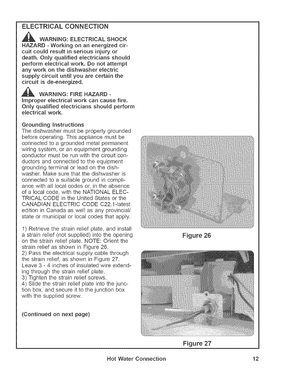
Grounding _nstructions
The dishwasher must be properly grounded
before operating. This appliance must be
connected to a grounded metal permanent
wiring system, or an equipment grounding
conductor must be run with the circuit con-
ductors and connected to the equipment
grounding terminal or lead on the dish-
washer. Make sure that the dishwasher is
connected to a suitable ground in compli-
ance with all local codes or, in the absence
of a local code, with the NATIONAL ELEC-
TRICAL CODE in the United States or the
CANADIAN ELECTRIC CODE C22.1=latest
edition in Canada as well as any provincial/
state or municipal or local codes that apply.
1) Retrieve the strain relief plate, and install
a strain relief (not supplied) into the opening
on the strain relief plate. NOTE: Orient the
strain relief as shown in Figure 26.
2) Pass the electrical supply cable through
the strain relief, as shown in Figure 27.
Leave 3 - 4 inches of insulated wire extend-
ing through the strain relief plate.
3) Tighten the strain relief screws.
4) Slide the strain relief plate into the junc-
tion box, and secure it to the junction box
with the supplied screw.
{Continued on next page)
Figure 26
Figure 27
Hot Water Connection 12
ELECTRICAL CONNECTION
(continued)
WARNING: F_RE HAZARD -LOOSE
OR _MPROPER ELECTRLCAL CONNEC°
T_ONS CAN CAUSE F_RE. MAKE CERTAIN
THAT ALL ELECTRICAL CONNECTIONS
ARE PROPERLY MADE.
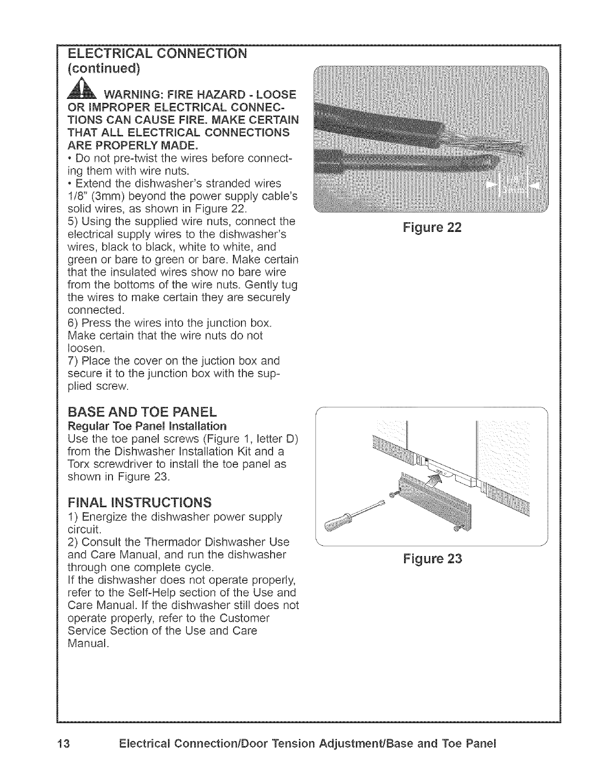
o Do not preotwist the wires before connect-
ing them with wire nuts.
o Extend the dishwasher's stranded wires
1/8" (3mm) beyond the power supply cable's
solid wires, as shown in Figure 22.
5) Using the supplied wire nuts, connect the
electrical supply wires to the dishwasher's
wires, black to black, white to white, and
green or bare to green or bare. Make certain
that the insulated wires show no bare wire
from the bottoms of the wire nuts. Gently tug
the wires to make certain they are securely
connected.
6) Press the wires into the junction box.
Make certain that the wire nuts do not
loosen.
7) Place the cover on the juction box and
secure it to the junction box with the sup-
plied screw.
BASE AND TOE PANEL
Regular Toe Pane_ installation
Use the toe panel screws (Figure 1, letter D)
from the Dishwasher Installation Kit and a
Torx screwdriver to install the toe panel as
shown in Figure 23.
FINAL INSTRUCTIONS
1) Energize the dishwasher power supply
circuit.
2) Consult the Thermador Dishwasher Use
and Care Manual, and run the dishwasher
through one complete cycle.
If the dishwasher does not operate properly,
refer to the Self-Help section of the Use and
Care Manual. If the dishwasher still does not
operate properly, refer to the Customer
Service Section of the Use and Care
Manual.
Figure 22
Figure 23
13 E_ectrica_ Connection/Door Tension Adjustment/Base and Toe Pane_

CUSTOMER SERVICE
Your Thermador dishwasher requires no special care other than that described in the Care
and Cleaning section of the Use and Care Manual. If you are having a problem with your
dishwasher, before calling for service please refer to the Self-Help section of the Use and
Care Manual. If service is necessary, contact your dealer or installer or an authorized serv-
ice center. Do not attempt to repair the appliance yourself. Any work performed by unauthoro
ized personnel may void the warranty.
If you are having a problem with your Thermador dishwasher and are not pleased with the
service
you have received, please take the following steps (in the order listed below) until the prob-
lem
is corrected to your satisfaction.
1. Contact your installer or the Thermador Authorized Service Contractor in your area.
2. Eomail us from the customer service section of our website, w_w.thermador.com.
3. Write us at the address below:
BSH Home Appliances, Corp.
5551 McFadden Avenue
Huntington Beach, CA 92649
4. Call us at 1o800o944o2904.
Please be sure to include (if you are writing), or have available (if you are calling), the fol-
lowing information:
- Model number
- Serial number
- Date of original purchase
- Date the problem originated
- Explanation of the problem
Also, if you are writing, please include a daytime phone number where you can be reached.
You will find the model and serial number information on the label located on the right-hand
side of the inner door of your dishwasher, see Figure 1. It will look similiar to this:
Please make a copy of your invoice and keep it with this manual.
Customer Service 14

Th mad
5551 McFadden Avenue, Huntington Beach, CA 92649 800f735-4328
9000001005 (8401) _:_2004 BSH Home Appliances Corp.
