TORNATECH VIZITOUCH2 HMI interface User Manual
TORNATECH Inc. HMI interface
User Manual

1
INSTALLATION AND MAINTENANCE MANUAL FOR
DIESEL ENGINE FIRE PUMP CONTROLLERS
AUTOMATIC CONTROLLER
MODEL GPD
2
3. Main Features
4. Home
5. Alarms
6. Configuration
7. History
8. Language
2. Installation
1. Introduction
Table of Contents
9. Service
1. Manuals
1. Technical Documents
GPDV2-Manual-EN
3
Table of Contents
Introduction ...................................................................................................................................................................... 5
Types of Diesel Engine Fire Pump Controllers .......................................................................................................... 5
Methods of starting/stopping ...................................................................................................................................... 5
Installation ....................................................................................................................................................................... 7
FCC Regulations and Radio Standards Specification (RSS) Rules .......................................................................... 7
Location ...................................................................................................................................................................... 8
Mounting .................................................................................................................................................................... 8
Wiring and Connections ............................................................................................................................................. 8
Water Connections ..................................................................................................................................................... 8
Electrical Wiring ......................................................................................................................................................... 8
Electrical Connections................................................................................................................................................ 9
Energy Consumption ................................................................................................................................................ 10
Incoming Power Connections .................................................................................................................................. 10
Circuit protection ...................................................................................................................................................... 10
Terminal Strips Descriptions .................................................................................................................................... 11
Quick Start-Up Guide ............................................................................................................................................... 12
Main Features ............................................................................................................................................................... 20
The ViZiTouch .......................................................................................................................................................... 20
Alarm bell ................................................................................................................................................................. 20
First Setup ................................................................................................................................................................ 21
Home ............................................................................................................................................................................. 22
Home (Menu) ........................................................................................................................................................... 22
Screen Saver ........................................................................................................................................................... 24
Alarms ........................................................................................................................................................................... 25
Configuration ................................................................................................................................................................. 29
Config (Menu) .......................................................................................................................................................... 29
NumPad Page .......................................................................................................................................................... 30
Date and Time Page ................................................................................................................................................ 31
User Login Page / KeyPad Page ............................................................................................................................. 31
Advanced Configuration Page ................................................................................................................................. 32
Update Program Page ............................................................................................................................................. 33
Config > Advanced > Software Update .................................................................................................................... 33
Sensor Selection ...................................................................................................................................................... 33
Alarms ...................................................................................................................................................................... 34
Control Timers .......................................................................................................................................................... 36
Outputs ..................................................................................................................................................................... 36
Factory Settings ....................................................................................................................................................... 37
IO Card Info .............................................................................................................................................................. 38
Network .................................................................................................................................................................... 38
Interlock Lockout ...................................................................................................................................................... 39
4
Reboot ViziTouch ..................................................................................................................................................... 39
Config > Advanced > Reboot Vizitouch ................................................................................................................... 39
History ........................................................................................................................................................................... 40
History (Menu) .......................................................................................................................................................... 40
Events Page ............................................................................................................................................................. 41
Pressure Curves ...................................................................................................................................................... 41
Power Curves ........................................................................................................................................................... 42
Saved Logs Select ................................................................................................................................................... 43
Pump Curve Selection ............................................................................................................................................. 44
Statistic selection ..................................................................................................................................................... 45
All Time Statistics ..................................................................................................................................................... 45
First Service Statistics .............................................................................................................................................. 46
Last Service Statistics .............................................................................................................................................. 47
Download ................................................................................................................................................................. 47
Language ...................................................................................................................................................................... 48
Service .......................................................................................................................................................................... 49
Manuals ......................................................................................................................................................................... 50
Technical Documents .................................................................................................................................................... 51

5
Introduction
Diesel engine fire pump controllers are designed to automatically start a diesel engine driven fire pump upon
detection of a pressure drop in the fire protection system. A diesel engine fire pump controller provides automatic
& manual starting and stopping. An automatic start is controlled by a pressure transducer or by remote automatic
devices such as a deluge valve. A manual start is controlled by remote manual button or by controller pushbutton.
The automatic shutdown option provides a 30-minutes automatic stop after automatic start once all starting
causes have returned to normal. The diesel engine fire pump controller includes two battery chargers to ensure
the engine batteries are continuously charged.
Types of Diesel Engine Fire Pump Controllers
FIRE PUMP CATALOG NUMBER
MODEL N° EXAMPLE: GPD-12-120
Model Prefix: GPD, GPDFM
Battery Voltage: 12=12v, 24=24v
Incoming Voltage: 120=110/120V 50/60Hz, 220=208/240V 50/60Hz
Methods of starting/stopping
The controllers are available as combination automatic / non-automatic with provision for manual or automatic
shutdown (automatic shutdown only possible after automatic start).
METHODS OF STARTING
AUTOMATIC START
The controller will start automatically on low pressure detection by the pressure sensor when the pressure drops
below the cut-in threshold.
MANUAL START
The engine can be started by pressing the CRANK 1 or and/or CRANK 2 push button, regardless of the system
pressure, when the Main Selector switch is in the HAND position. The Fuel Solenoid Valve will open as soon as a
CRANK button is pressed and will remain in this state.
REMOTE MANUAL START
The engine can be started from a remote location by momentarily closing a contact of a manual push button.
REMOTE AUTOMATIC START, DELUGE VALVE START
The engine can be started from a remote location by momentarily opening a contact connected to an automatic
device. The controller must be in automatic mode.
SEQUENTIAL START
In case of a multiple pump application, it may be necessary to delay the starting of each motor when there is a
water pressure drop to prevent simultaneous starting of all motors.
FLOW START, HIGH ZONE START
6
The controller can be started by opening/closing a contact on the FLOW/ZONE START/STOP input.
WEEKLY START
The engine can be started (and stopped) automatically at the preprogrammed time.
TEST START
The motor can be started automatically for a preprogrammed time by pressing the run test button.
METHODS OF STOPPING
MANUAL STOP
Manual stop is done by pressing the STOP push button. Note that pressing the stop push button will stop the
engine only if all starting causes have disappeared.
AUTOMATIC STOP
The automatic stop is possible only after an automatic start and this function has been activated. When this
function is Enabled, the motor is automatically stopped 30 minutes (adjustable) after the restoration of the
pressure (above the cut-out threshold) given that no other run cause is present.
FLOW STOP, HIGH ZONE STOP
If the controller has been started by the FLOW/ZONE START/STOP input and the signal has returned to normal,
the motor will be stopped given that no other run cause is present.
EMERGENCY STOP
The emergency stop is always possible in any running condition and is done by positioning the main selector
-switch to the OFF position.

7
Installation
This diesel controller is UL listed and FM certified. The controller is built in accordance with the latest edition of the
National Fire Protection Association standard for the Installation of Centrifugal Fire Pumps, NFPA No.20
(Centrifugal Fire Pumps 2013 Edition). The controller is intended to be installed in accordance to NFPA 20-2013
and
in the USA National Electrical Code NFPA 70
In Canada Canadian Electrical Code, Part 1
Others * Local Electrical Codes *
* Only American and Canadian applicable codes have been considered during the design of the controllers and the
selection of components.
Except in some cases, the controller is also seismic approved and has been tested in accordance with the ICC-ES
AC156, IBC 2015 & CBC 2016 standards. Proper installation, anchoring and mounting is required to validate this
compliance report. Refer to this manual and drawings to determine the seismic mounting requirements and location
of the center of gravity (you may need to contact factory). The equipment manufacturer is not responsible for the
specification and performance of anchorage systems. The structural engineer of record on the project shall be
responsible for anchorage details. The equipment installation contractor shall be responsible for ensuring the
requirements specified by the structural engineer of record are satisfied. If detailed seismic installation calculations
are required, please contact the manufacturer for the performance of this work.
FCC Regulations and Radio Standards Specification (RSS) Rules
To comply with FCC and Industry Canada RF exposure compliance requirements, a separation distance of at least
20 cm must be maintained between the antenna of this device and all nearby persons. This device must not be co-
located or operating in conjunction with any other antenna or transmitter.
This device complies with Industry Canada licence-exempt RSS standard(s). Operation is subject to the following
two conditions: (1) this device may not cause interference, and (2) this device must accept any interference,
including interference that may cause undesired operation of the device.
CAN ICES-3 (A)/NMB-3(A)
This device complies with part 15 of the FCC Rules. Operation is subject to the following two conditions: (1) This
device may not cause harmful interference, and (2) this device must accept any interference received, including
interference that may cause undesired operation.
Note: This equipment has been tested and found to comply with the limits for a Class A digital device, pursuant to

8
part 15 of the FCC Rules. These limits are designed to provide reasonable protection against harmful interference
when the equipment is operated in a commercial environment. This equipment generates, uses, and can radiate
radio frequency energy and, if not installed and used in accordance with the instruction manual, may cause harmful
interference to radio communications. Operation of this equipment in a residential area is likely to cause harmful
interference in which case the user will be required to correct the interference at his own expense.
“Changes or modifications not expressly approved by the party responsible for compliance could void the user’s
authority to operate the equipment.”
Location
The controller shall be located as close as practical to the engine/motor it controls and shall be within sight of the
engine/motor. The controller shall be located or protected such that it will not be damaged by water escaping from
pump or pump connections. Current carrying parts of the controller shall be not less than 12 in. (305 mm) above the
floor level.
Working clearances around controller shall comply with NFPA 70, National Electrical Code, Article 110 or C22.1,
Canadian Electrical Code, Article 26.302 or other local codes.
The controller is suitable for use in locations subject to a moderate degree of moisture, such as a damp basement.
The pump room ambient temperature shall be between 39°F (4°C) and 104°F (40°C) (If a temperature option is
included, see the rating label for maximum temperature).
The standard controller enclosure is rated NEMA 2. It is the installer’s responsibility to insure that either the
standard enclosure meets the ambient conditions or that an enclosure with an appropriate rating has been
provided. Controllers must be installed inside a building and they are not designed for outside environment. The
paint color may change if the controller is exposed to ultraviolet rays for a long period of time.
Mounting
The fire pump controller shall be mounted in a substantial manner on a single incombustible supporting structure.
Wall mounted controllers shall be attached to the structure or wall using all four (4) mounting ears provided on the
controller with hardware designed to support the weight of the controller at a height not less than 12 in. (305 mm)
above floor level. Floor mounted controllers shall be attached to the floor using all holes provided on the mounting
feet with hardware designed to support the weight of the controller. The mounting feet provide the necessary 12 in.
(305 mm) clearance for current carrying parts. For seismic applications, mounting arrangement should be rigid wall
and base only. The structural engineer of record on the project shall be responsible for anchorage details.
Wiring and Connections
Water Connections
The controller must be connected to the pipe system according to the latest edition of NFPA20 and also to a drain
pipe. The water connections are on the left side of the controller. The connection to the system pressure is a Male
½ NPT. The connection to the drain is a tapered connection for plastic tubing.
Electrical Wiring
The electrical wiring between the power source and the diesel engine fire pump controller shall meet the NFPA 20,
Chapter 12.3.5.1, 12.3.5.2 and 12.2.5.3, NFPA 70 National Electrical Code Article 695 or C22.1 Canadian Electrical
Code, Section 32-200 or other local codes.

9
Electrical Connections
A licensed electrician must supervise the electrical connections. The dimension drawings show the area suitable for
incoming power and motor connections. No other location shall be used. Only watertight hub fittings shall be used
when entering the cabinet to preserve the NEMA rating of the cabinet. The installer is responsible for adequate
protection of the fire pump controller components against metallic debris or drilling chips. Failure to do so may
cause injuries to personnel, damage the controller and subsequently void warranty.
10
Energy Consumption
Diesel Controller with boost charger
Model / State
120VAC
220/240VAC
VDC Output
12VDC / @
No charge
1.0A
1.0A
13.8V
12VDC / @
Full charge*
6A
4A
24VDC / @
No charge
1.0A
0.5A
27.6V
24VDC / @
Full charge**
9A
6A
*12 amps through each battery
**10 amps through each battery
Incoming Power Connections
Diesel engine driven fire pump controllers shall be powered by a dedicated source protected by a fuse or circuit
breaker. Verify the label on the cabinet to select the correct protection. Always follow this procedure when
connecting or disconnecting the controller: Connect both batteries before connecting the AC power. Disconnect the
AC power before disconnecting the batteries. Disconnecting the batteries while the AC is connected may result in
severe damage to the controller electronic boards.
Circuit protection
CB1 protects battery charger 1 and CB2 protects battery charger 2. CB3 protects the control circuit from battery 1
and CB4 protects the control circuit from battery 2. Always follow this procedure when connecting or disconnecting
the controller: Connect both batteries before connecting the AC power. Disconnect the AC power before
disconnecting the batteries.
11
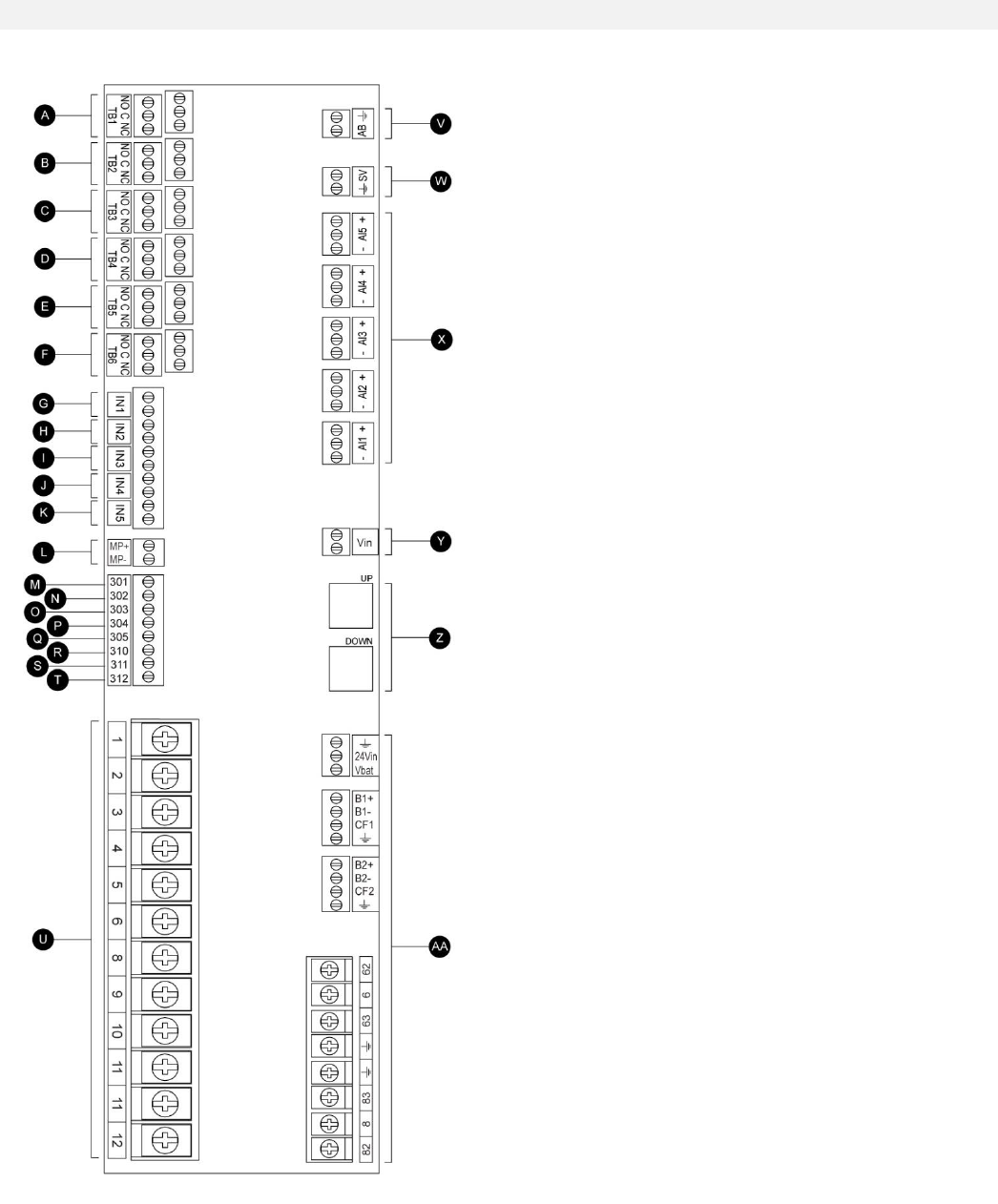
Terminal Strips Descriptions
A-F : Alarm Output Terminals
(DPDT Relay, 11/21:Common, 12/22:Normally Closed,
14/24:Normally Open):
A Controller Trouble (Fail safe)
B Engine Run
C Main SS in Manual position
D Main SS in OFF position
E Engine Trouble
F Pump Room Alarm
G-T : Field Inputs Terminal
(Dry Contact Only: Voltage Free):
G Low Fuel Level (NO)
H Remote Automatic Start (NC)
I Deluge Valve Start (NC)
J Fuel Tank Leak (NO)
K High Fuel Level (NO)
L Engine RPM Magnetic Pickup
M ECMS Elec. Ctrl. Switch in Alternate Position
N FIM Fuel Injection Malfunction
O ECMW Elec. Ctrl. Warning
P ECMF Elec. Ctrl. Fault
Q PLD Low Suction Pressure
R High Raw Water Temperature
S Low Raw Water Flow
T LET Low Engine Temperature
U : Engine Terminals :
The terminals are numbered according to the standard:
1 FS : Fuel Solenoid Valve
(ETR - Energized To Run)
2 ER : Engine Run contact
3 OS : Engine Overspeed contact
4 OP : Engine Oil Pressure contact
5 WT : Engine Coolant Thermostat contact
6 B1 : Battery #1 positive
8 B2 : Battery #2 positive
9 C1 : Start Contactor #1
10 C2 : Start Contactor #2
11 GND : Ground
12 ST : Stop Fuel Solenoid Valve
(ETS - Energized To Stop)
V-AA : Bell / Solenoid Valve / Analog inputs
V Bell output
W Test Solenoid Valve
X Analog inputs
AI1 Discharge Pressure transducer
AI2 Optional additional Discharge Pressure transducer
AI3 Water Level or Suction Pressure transducer
AI4 Fuel Level analog input
AI5 Flow or Spare Temperature analog input
Y AC monitoring
Z CANBUS: UP to ViZiTouch, DOWN to Exp. IO board
AA Factory reserved power connections
12
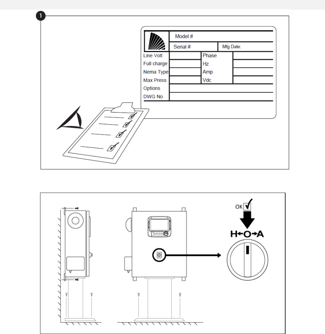
Quick Start-Up Guide
The rating label is the most important label. It must be read carefully to ensure the compatibility between the
controller and the installation.
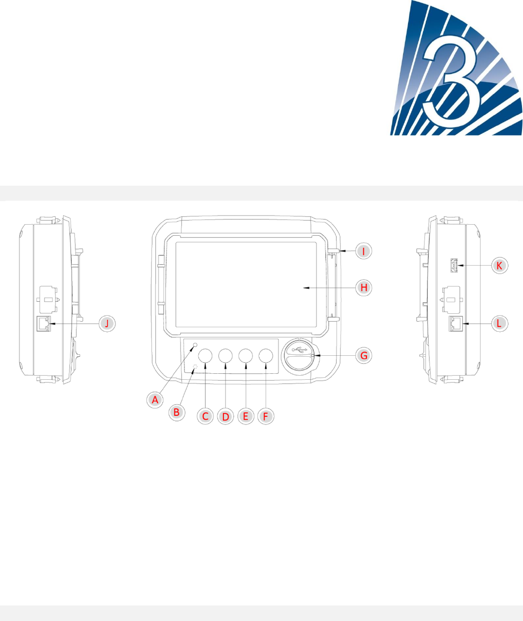
Verify that the controller is installed securely to the wall, or on the mounting stand (optional). Verify the Main
Selector Switch is in the “OFF” position. This selector switch is also called the “HOA” and can be placed in 3
positions: “H” Hand/Manual, “O” OFF, “A” Automatic.
13
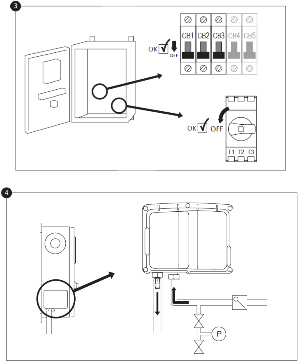
Open the controller’s door and verify that the disconnect switch and all circuit breakers are in the “OFF” position.
Verify and/or install the proper water connections for the water input and the drain. They must be securely installed
and tightened. Refer to the silkscreen markings on the plastic cover.
14
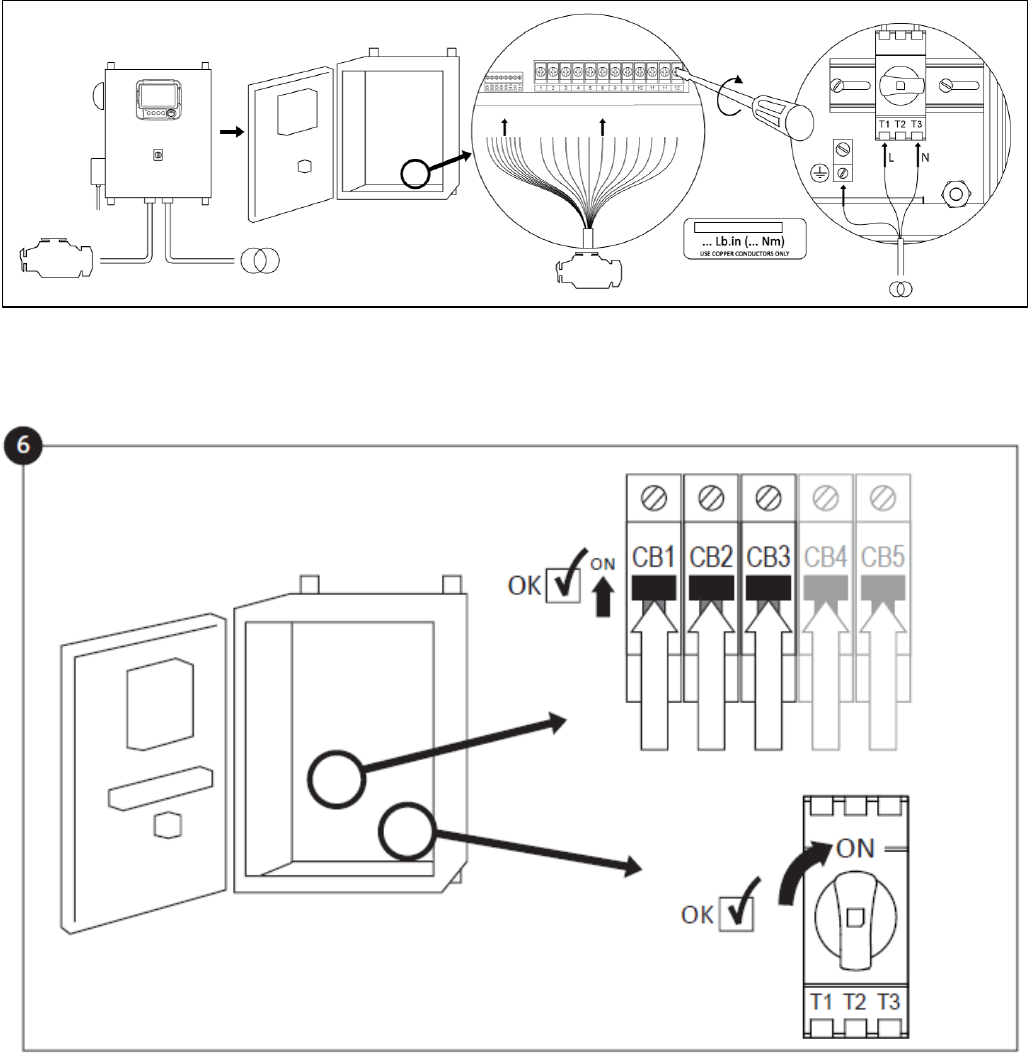
Connect all cables between the engine control panel and the controller engine terminals (Identified as “U” on the IO
board diagram displayed in the Terminal Strips Descriptions in the manual). Secure with the appropriate torque as
indicated on the torque label and verify all connections. Connect the AC main line and ground to the AC terminal in
the controller.
Activate the disconnect switch and all breakers by setting them to the ON position. The controller will boot up for the
first time.
15
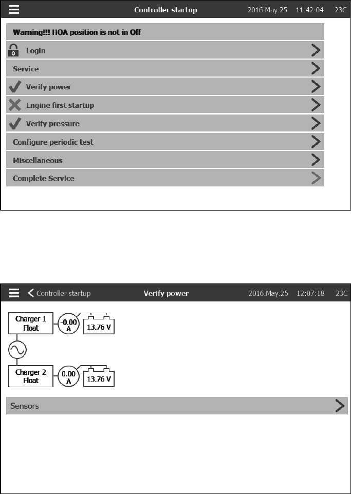
The “Controller Startup” page replaces the Homepage until the “First Setup” is done. To come back to this page,
press the 3 lines in the top left corner and chose the House symbol. First, press on “Login” and enter a valid
authorization code. Then, press “Service” and select the frequency of the “Service” needed. After that, press on
“Verify power”.
On this page, it’s possible to calibrate the voltage and curent. To do so, press on the “Sensors” button and follow
the calibration instructions on section 6 Configuration˃Sensors of the manual.
Press on the “Engine first Startup” and turn the Main Selector Switch to the “HAND” position.
16
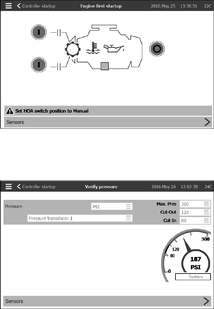
Before trying to start the engine, verify that the engine setup is complete (by an authorized engine representative or
service dealer) and the exhaust pipe is connected properly. For the engine first startup, press on one or both of the
green Crank buttons on the membrane. Verify that the engine has started and is running properly. Make sure there
is no alarm is present and press the red stop button on the membrane. Go back to the controller startup page and
press the “Verify pressure” button.
Select the controller pressure units, cut-in and cut-out. Verify that all other parameters on the setup page are
correct. Go back to the controller startup page and press the “Configure periodic test” button.
17
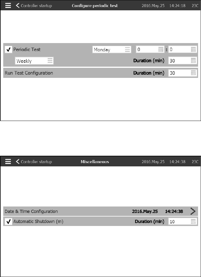
Select the frequency at which the periodic test will occur, the day of the week, the hour and the duration of the test.
Also, enter the duration of the Manual Run Test. Go back to the controller startup page and press the
“Miscellaneous” button.
Enter the time and date. Select the “Automatic shutdown” and the duration the engine will keep running after the
automatic stop.
When satisfied with the controller settings, go back to the controller startup page, acknowledge the changes by
pressing the “Complete Service” button. If this button is unavailable (grey), ensure that a sufficient authorization
code has been entered.
18
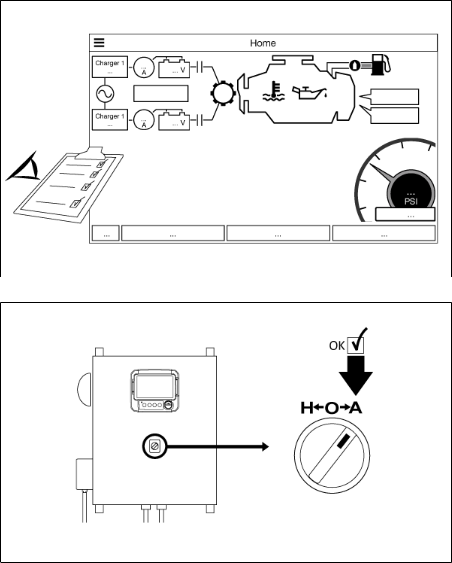
Verify that the displayed values are correct.
Turn the “Main Selector Switch” to the “AUTO” position. This is the preferred position and from now on, the “Main
Selector Switch” should always remain in that position.

19
The first Setup is now completed. The controller is fully installed and configured.
20
Main Features
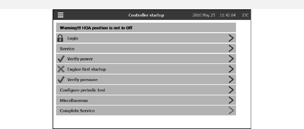
The ViZiTouch
A- Power LED 3 colors: Pulsing green if the ViZiTouch is properly powered.
B- Temperature Sensor.
C- Crank 1 button: Used to manually crank the starter from battery 1 while in “HAND” mode.
D- Crank 2 button: Used to manually crank the starter from battery 2 while in “HAND” mode.
E- Stop button: Used to stop the engine if all starting conditions are gone.
F- Run Test button: Used to start the manual run test. Be aware that water will flow through the drain during the
test.
G- Front USB Connector: USB Device connector used for file download, software updates, service reports.
H- Touch Screen: 7 inch color touch screen LCD with protective cover.
I- Locking mechanism for the protective cover of the screen. Push to open.
J- CANBUS connector for communication with IO board.
K- Side USB connector.
L- Ethernet connector.
Alarm bell
The alarm bell is activated under the default condition stated by the NFPA20 standard. Other optional or user
defined conditions can also activate the bell and can be configured by the user. See section 5 for more details.
Any of these conditions will energize the alarm bell but may be silenced, except in some cases, by pressing on the
the “Silence bell” button on the Alarms page. When silenced, the alarm bell will restart ringing if a new default
occurs or if the alarm conditions remain unchanged after 24 hours. The alarm bell automatically stops ringing if
21
alarm conditions are not present anymore.
First Setup
The First Setup must be done prior to using the controller. Completing the First Setup is the only way to access the
homepage and enable the automatic mode of the controller. The complete procedure can be found in the “Quick
Start-Up Guide” that can be download from the controller. A printed version is also supplied with the controller.
22
Home
Home (Menu)
Home
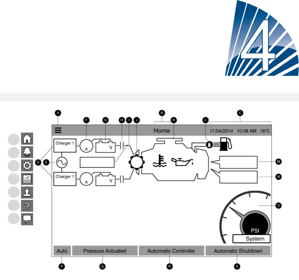
The home page displays all controller statuses and important values of the controller. This includes all voltages,
currents, pressure, engine state and status, as well as all timers and cranking sequences.
A- Navigation bar: Pressing this icon will open a navigation menu on the left side of the screen:
1-Home page
2-Alarms page
3-Configuration page
4-History page
5-Service Page
6-Manual Language selection page
7-Language page
Pressing on one of these buttons will redirect to the corresponding page.
B- Name of the page
1
2
3
4
5
6
7
23
C- Displays the date, time and exterior temperature.
D- The battery charger state: It may become one of three colors and also explicitly describes the current battery
charger state.
POWER UP – Green
BULK* – Green
OVER_CHARGE – Green
FLOAT – Green
CHARGER_FAIL – Red
NO_AC – Grey
BOOST_FAULT- Red
*The Bulk charging mode enables the boost function on the charger, allowing highier voltage that shorten the
charging time of the battery.
E- AC status: Red when there is a failure and green otherwise.
F- Amp meter: Displays the actual current between the charger and the battery in amps.
G- The battery: The battery will be red if it is in failure and green otherwise. The data shows the actual voltage of
the battery and the charger in volts.
H- Starter contactor: Grey when non active (open) and green when they are activated (closed) during a crank.
I- Starter state window: This window only appears during a cranking cycle. The counter inside indicates the step
timer, ranging from 15 to 0 seconds. As there are two cranking modes, “waiting for crank” and “cranking”, two
symbols will alternate: a gear during cranking mode and an hourglass during the waiting mode.
J- The starter gear: Grey when non active and green when activated during cranking.
K- The diesel engine: It will be grey if the engine is stopped, green if an “Engine Run” signal is detected and red if a
“Fail to start” occurred, after 6 unsuccessful cranking attempts. Inside the engine two major alarms are represented;
the “low oil pressure” alarm and the “engine high temperature” alarm. These alarms will stop the engine only if it is
running in test mode. When active, the appropriate alarm symbol will turn red.
L- Fuel solenoid valve: This valve controls the flow of fuel to the engine. When the fuel solenoid is activated, the
valve will be horizontal, green and the yellow representation of the fuel will flow through the entire pipe. When the
“Stop Solenoid valve” is activated, the valve will rotate vertically, become red and the yellow representation of the
fuel will stop at the valve, indicating that the fuel does not flow through anymore.
M- Motor starting or stopping cause: A grey box will indicate the reason why the motor is running.
Starting reasons:
LOCAL: This start cause is triggered if the engine is locally started directly from its own control panel and the option
is Enabled.
MANUAL: The controler receives a manual crank request from one or both of the manual crank membrane buttons
while the selector switch is the “HAND” position.
REMOTE MANUAL: Manual engine starting is activated by a remote start contact.
DELUGE: Automatic engine starting is activated by a deluge valve.
AUTO: Automatic engine starting is activated by pressure drop.
REMOTE AUTO: Automatic motor starting is activated by remote equipment

24
FLOW: Automatic motor starting is activated by a signal in the FLOW/ZONE START/STOP input.
HIGH ZONE: Automatic motor starting is activated by a signal in the FLOW/ZONE START/STOP input.
WEEK TEST: Automatic motor starting is activated by a scheduled test.
MANUAL TEST: Automatic motor starting is activated by the run test pushbutton.
AC FAIL: AC Fail will count the time following an AC Failure and at the end of a predetermined time, will start the
engine with an AC FAIL request.
A red rectangular box will indicate the reason why the engine is not running despite the fact that a request is being
made. Possible choices are:
OVERSPEED: This start cause happens when the controller receives a request to start, but the engines sends an
“Overspeed” signal, thus preventing its ability to effectively start the engine.
FAILSTART: This start cause happens when the controller receives a request to start, but a “Fail To Start” alarm is
active after a cranking sequence failure, thus preventing its ability to effectively start the engine.
LOW ZONE: A not running lower zone controller prevents the motor from running. This functionality is optional.
LOCKED: An interlock signal is preventing the motor from running.
N- Operations timers: This includes the sequential start timer, the run period shutdown timer, the manual test timer,
the weekly test timer and the AC Fail timer.
O- The pressure gage: It allows for a precise reading of the actual system pressure. The cut-in and cut-out are
represented by a red and green line on the gage, allowing a quick comparison between the actual pressure and the
set points. At the center of the gauge, a digital indicator shows the actual discharge pressure represented also by
the needle of the gauge. Just under of the digital pressure indicator, the actual pressure unit is shown. The
maximum allowable pressure is also indicated on the gauge and will scale the gauge accordingly.
P- HOA Indicator: Displays the current mode. Hand, Off, Automatic.
Q- Actuation Mode: Displays if the controler is Pressure Actuated or Non-Pressure Actuated.
R- Controler type: Displays if the controler is an Automatic or Non-Automatic type.
S- Shutdown mode: Displays if the shutdown on this controler is Automatic or Manual.
Screen Saver
The screen saver's goal is to expand the lifetime of the LCD screen. The screen saver will be instantly deactivated if
the engine is running or if an alarm is activated. To manually deactivate it, simply touch the screen or any
membrane button. After deactivation, the screen saver will always redirect to the “Home” page. It will also log off
any user by resetting the security level to 0.
25
Alarms
Alarms (Menu)
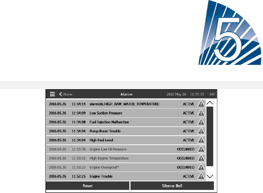
This page displays the list of currently active and occurred alarms. Alarms with adjustable parameter can be set in
the Config ˃ Advanced ˃ Alarms pages (see section 6).
An alarm is called ACTIVE when its triggering condition is still valid.
An alarm is called OCCURRED when its triggering condition has been active, but is no longer true.
Alarms representing serious concerns will have a red triangle with an exclamation point in the center at the end of
the alarm message.
Alarms representing simple warnings will have a yellow triangle with an exclamation point in the center at the end of
the alarm message.
Pressing on the Bell Test button will ring the bell for three seconds.
To silence the bell, press the ALARM button or it will silence itself after the expiration of a factory set time.
Pressing on the RESET button will reset OCCURRED alarms only.
The table displays system events:
- Date and time stamp of the alarm in the YYYY.MM.DD format.
- Alarm message.
- State: OCCURRED or ACTIVE.
- Color Code Icon.
- Red: The event is an alarm.
- Yellow: The event is a warning.
Complete list of alarms:
Common Alarms:
Engine Trouble: A common alarm that is activated when one or more of these conditions are active :
26
- High Coolant Temperature (5)
- Engine Low Coolant Temperature (312)
- Engine Low Oil Pressure (4)
- Engine Fail to Start
- Engine Fail when Running
- Engine Overspeed* (3)
- ECM Selector Switch in Alternate Position (301)
- ECM Fault (304)
- Engine Fuel Injection Malfunction (302)
- PLD Low Suction Pressure (305)
- High Raw Water Temperature (310)
- Low Raw Water Flow (311)
- Battery Failure 1-2
- DC Failure
- Over Pressure
Pump Room Trouble: A common alarm that is activated when one or more of these following events occur:
- Fuel Tank Leak
- Low Fuel Level
- High Fuel Level
- AC Failure
- Low Pump Room Temperature
- Low Suction Pressure
- Water Reservoir Low
- Water Reservoir Empty
CTRL Trouble: Important: this relay is normally energized when the controller is in normal condition. The relay is
de-energized when controller trouble is detected (fail safe). The controller trouble common alarm is active when one
or more of these conditions are active :
- Charger Failure 1-2
- DC failure
- Default Solenoid Valve
- Weekly Test Cut-In Not Reached
- AC Failure: Monitors the AC power and activates on a failure.
- DC Failure: Monitor the DC power from the batteries and activates if both batteries fail.
- Battery 1-2 Fail: Monitors the status of batteries and activates on a failure. This occurs when the battery is
disconnected, is of the wrong type or is unable to be recharged.
- Charger 1-2 Fail: Monitors the state of battery chargers and activates on a failure. This occurs when the battery
charger has a defect, is not properly powered, or is unable to provide the needed current. The charger will also
change to Boost Fault mode if during a boost test, the voltage does not rise. A NC dry contact is also connected
from the charger to the IO Board. The alarm will activated if this contact open for the time set on the Charger Fail
alarm page. Charger readings are not updated during cranking and/or running, due to reading instability under load.
As soon as the engine returns to an idle state, all readings and failure analysis are reactivated.
- Service Required: Activates when service is due for the controller. This occurs when the date set in the service
page has passed, or if no service has ever been done.
- Weak Battery 1-2: Activates if the battery voltage falls below the weak battery factory set point.
- Loss of Continuity 1-2: Activates if the engine start contactors are disconnected from the controller.
- Weekly Test Cut-In Not Reached: Activates if the Cut-In is not reached during a manual or a weekly run test. At
the end of the 255s timer, if the Cut-In is not reached, the test may still be successful at starting the engine if the
pressure has dropped by at least 5 PSI.
27
- Check Weekly Test Solenoid: Activates if the pressure does not drop a minimum of 5 PSI during the manual run
test or the weekly test. Indicates a failure with the Test Solenoid Valve.
- Pressure Transducer fault detected: If an optional dual pressure sensor is installed, it will be activated if the two
pressure transducers show different readings. Further investigation is advised to determine what caused the
different readings. Note that the controller will always choose the lowest pressure reading to determine the actual
system pressure. Also, if the voltage powering the transducer is below 0.5V or over 4.5V the alarm will be activated.
- Overpressure: Activates if the analog readout of the discharge pressure goes higher than the overpressure set
point in the alarm page.
- Underpressure: Activates if the analog readout of the discharge pressure goes lower than the “Under Pressure”
set point in the alarm page.
- Low Suction Pressure: Activates if the analog readout of the suction pressure is Enabled and goes lower than the
low suction pressure set point in the alarm page.
- Water Reservoir Low: Activates if the “Water Reservoir Low” contact input is triggered or if the analog readout of
the water reservoir is Enabled and is lower than the water reservoir low set point in the alarm page.
- Fuel Tank Leak: Activates if the “Fuel Tank Leak” contact input (IN4) is triggered.
- Low Fuel Level: Activates if the “Low Fuel Level” contact input (IN1) is triggered or if the analog readout of the fuel
level is Enabled and goes lower than the low fuel level set point alarm.
- High Fuel Level: Activates if the “High Fuel Level” contact input (IN5) is triggered or if the analog readout of the
fuel level is Enabled and goes higher than the high fuel level set point alarm.
- Engine Fail When Running: Activates if the “Engine Run” signal is lost while the engine is running. The engine will
try to start the cranking sequence once again if the starting causes are not back to normal.
- Engine Fail to Start: Activates if the engine fail to start after the complete 6 attempts crank sequence. The engine
will turn red.
- ECM Selector Switch in Alternate Position: Activates if the specific “ECM” (Electronic Control Module) input (301)
is triggered on the engine connector strip.
- ECM Warning: Activates if the specific “ECM” input (303) is triggered on the engine connector strip.
- ECM Fault: Activates if the specific “ECM” input (304) is triggered on the engine connector strip.
- FIM: Activates if the specific FIM (Fuel Injection Malfunction) input (302) is triggered on the engine connector strip.
- PLD Low Suction Pressure: Activates if the specific PLD (Pressure Limiting Device) input (305) is triggered on the
engine connector strip.
- High Raw Water Level: Activates if the specific input is (310) triggered on the engine connector strip.
- Low Raw Water Flow: Activates if the specific input (311) is triggered on the engine connector strip.
- Engine High Temperature: Activates if the specific “High Temp” input (5) is triggered on the engine connector strip
and the engine is running. A 3 hour timer will start when the engine stops, and if the condition is still present, the
alarm will be activated. This alarm will stop the engine only if triggered during a manual run test or a weekly test.
- Engine Low Temperature: Activates if the specific “Low Temp” input (312) is triggered on the engine connector
strip.
- Engine Low Oil Pressure: Activates if the specific “Low Oil Pressure” input (4) is triggered on the engine connector
strip and the engine is running. This alarm will stop the engine only if triggered during a manual run test or a weekly
28
test.
- Engine Overspeed*: Activates if the specific “Overspeed” input (3) is triggered on the engine connector strip and
the engine is running. This alarm will immediately stop the engine and cannot be reset by using the reset button on
the alarm page. The alarm must be reset on the engine itself and the controller must be turned OFF and ON with
the HOA selector switch to complete the reset procedure for this alarm.
- Battery1-2 Overvoltage: Activates if the voltage of the specific battery is higher than the specified overvoltage set
point.
- Water Reservoir High: Activates if the optional “Water Reservoir High” contact input is triggered or if the analog
readout of the water level is Enabled and goes higher than the “High Water Level” set point alarm page.
- IO Exp Comm Error: Activates if communication with the Expansion IO board could not be established for 15
seconds.
- Pump on demand: Activates when the pressure is below the cut-in set-point on an automatic pressure actuated
controller.
- Cooling No Flow
- Auto Mode Bypass:
- Bell Silenced: Activates when a audible alarm has been silenced.
- Engine Run: Activates when the input “Engine Run“ (2) is active on the engine strip of the IO card.
- Communication System Failure
- Invalid Cut-In: Activates when the Cut-In value is not acceptable. (0 or higher than the Cut-Out).
- Test Mode: Activates when a level 10 authorization code is entered.
- Incompatible Expansion IO Card
- Incompatible Diesel IO Card
- Incompatible ViziTouch PCB
- Disk Full
- User Alarm 1-20: Can be configured by the user. See setion 6 Configuration˃Alarms for more details.
29
Configuration
Config (Menu)
Config
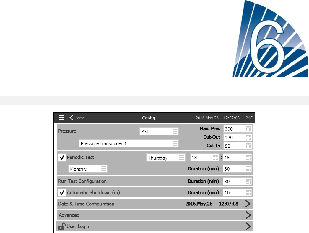
The main configuration page is used to setup all basic configuration parameters and provides a quick means of
changing the most common settings.
There are seven (7) access parameter boxes; Pressure, Periodic Test, Run Test, Automatic Shutdown, Date &
Time, Advanced and User Login. Each parameter requires a specific access level to set or change values.
User Login:
The padlock icon indicates the current authorization level. A locked padlock indicates that only basic settings can be
changed. Press on the padlock to enter an authorization code to unlock additional settings. An unlocked padlock
showing an authorization number indicates that some settings are unlocked. Press on the padlock again when you
have concluded your operation to logout and to save any changes made in the configuration.
Pressure:
The main pressure parameters can be set inside the box at the top of the page.
-Pressure reading: Can be selected as PSI, kPa, bar, FoH, or mH20.
-Input Device: Can be selected as Pressure transducer 1 or 2
-Maximum Pressure: Can be set between the Cut-Out value and 9999.
-Cut-Out: Can be set between the Cut-In value and the Maximum Pressure value. (The Cut-Out should -be set
before the Cut-In)
-Cut-In: Can be set (between 0 and the Cut-Out value)
Periodic Test:
The Periodic Test can be selected as “Weekly”, “Bi-Monthly” or “Monthly”. The day of the week, time of day for the
test and test Duration can also be specified in this box.
30
Run Test Configuration:
The Run Test Configuration box is where the duration of the run test time is set. A timer between 1 and 30 minutes
can be selected.
Automatic Shutdown:
If enabled, the Automatic Shutdown will automaticly stop the engine after the demand dissapears. A timer between
1 and 1440 minutes can be selected.
Advanced:
Selecting the blue arrow at the right side of the Advanced box activates the advanced configuration pages.
Date & Time Configuration:
Select to display the Date Time page.
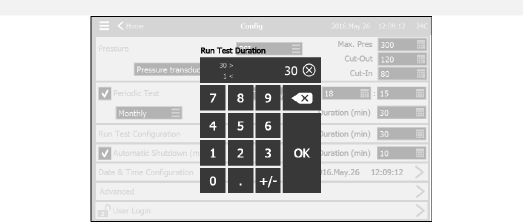
NumPad Page
The NumPad is activated every time the user presses on a white square box representing a number that can be
set. On top of the NumPad, the current parameter is shown. The box at the top of the NumPad displays the Min and
Max range of values accepted for that particular parameter. The box will turn red if the value entered is out of
range. Pressing the “X” button in the circle will set the value to zero “0”. Once a value that falls within the range is
selected, the box will turn blue. The button with a blue “X” inside a white arrow is used as a “backspace”. Pressing
the “OK” button will enter the new value and the screen will return to the previous page.
31
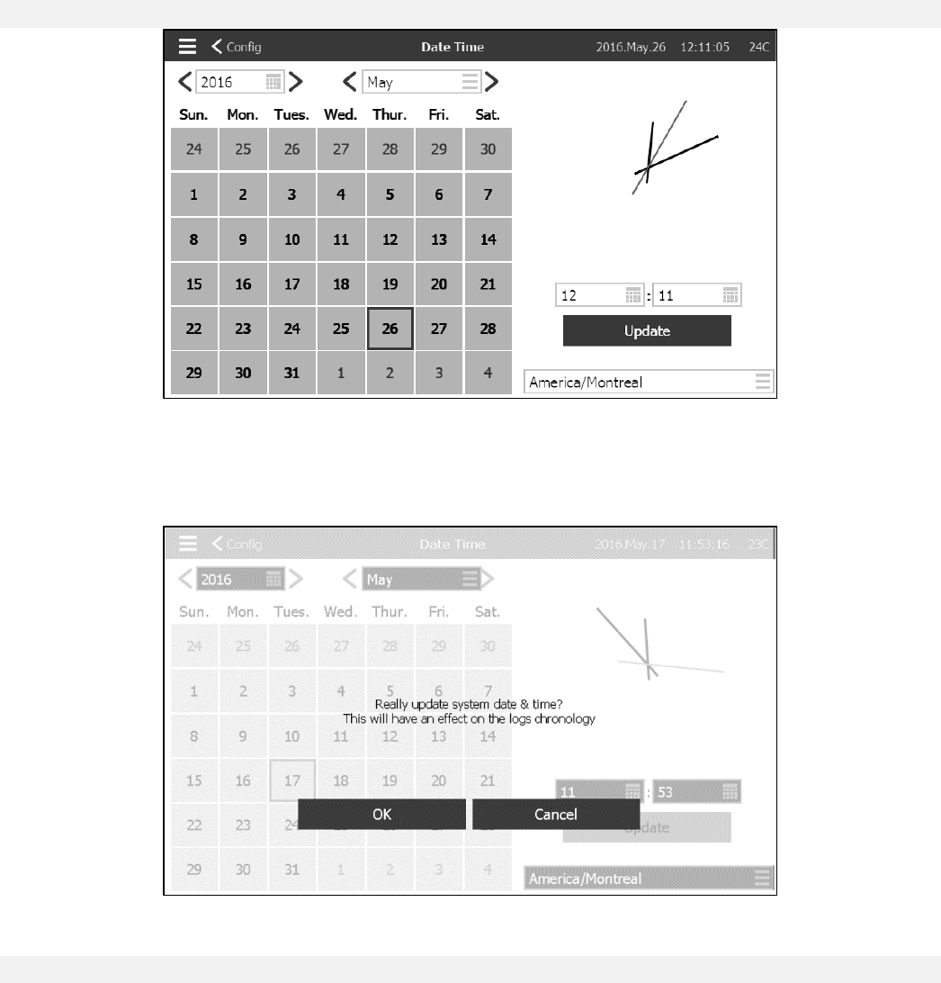
Date and Time Page
This page is used to change the time and date. Using the two white boxes on top and the calender, the year, month
and the day can be chosen. The two white boxes under the clock are used to change the hour and minutes.
Pressing the blue “Update” button will update the changes made. The time zone can also be changed using the box
in the bottom-right corner.
WARNING : Any change made on this page can have effects on the log chronology.
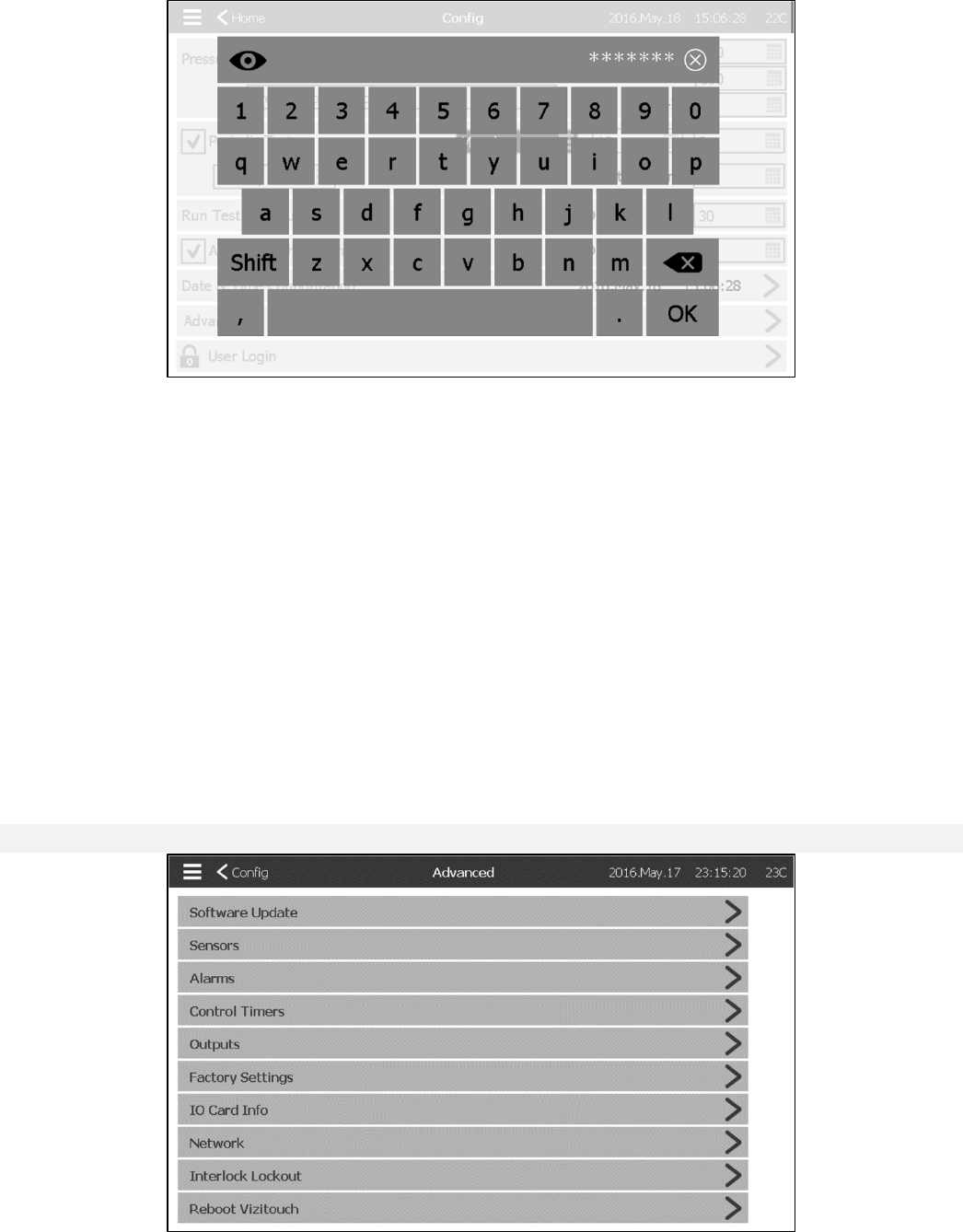
User Login Page / KeyPad Page
32
User Login KeyPad:
This page allows the user to log into a higher security level by entering a password. If the password is valid, the text
field will turn green and if it is invalid, the text field will turn red. An “X” button appears in the text field as soon as a
character is entered, allowing for a quick erase of the written password.
Shortly after being entered, each character will be displayed as an “*”. To view the whole password, press the eye
on the top left corner.
If the password is invalid for a consecutive number of times, the user will be redirected to the “Service Dealer” page,
allowing the user to communicate with the appropriate Service Dealer.
If the password is valid, the “Configuration” page will reload and the access security level will be shown inside the
lock. To log off, click on the lock and the user security level will return to “0”
Other KeyPads:
The KeyPad is activated every time the user presses on a grey rectangle box with white text representing a text that
can be set. The “X” button allows the user to cancel editing the value. The back arrow erases the last entered
character. Simply click the “OK” button once the value is set. This type of text field is mostly used to generate a
digital text indication for a custom alarm input.
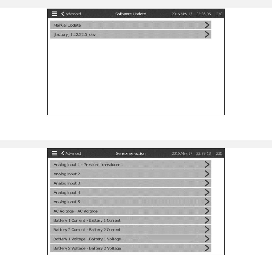
Advanced Configuration Page
Config > Advanced
33
This page is the portal to all the advanced configuration parameters of the ViZiTouch. It leads to 10 other pages:
Update Program Page
Config > Advanced > Software Update
This page is used to update the controller software. A USB key or a network connection with the software update is
needed. The controller cannot update to an older version.
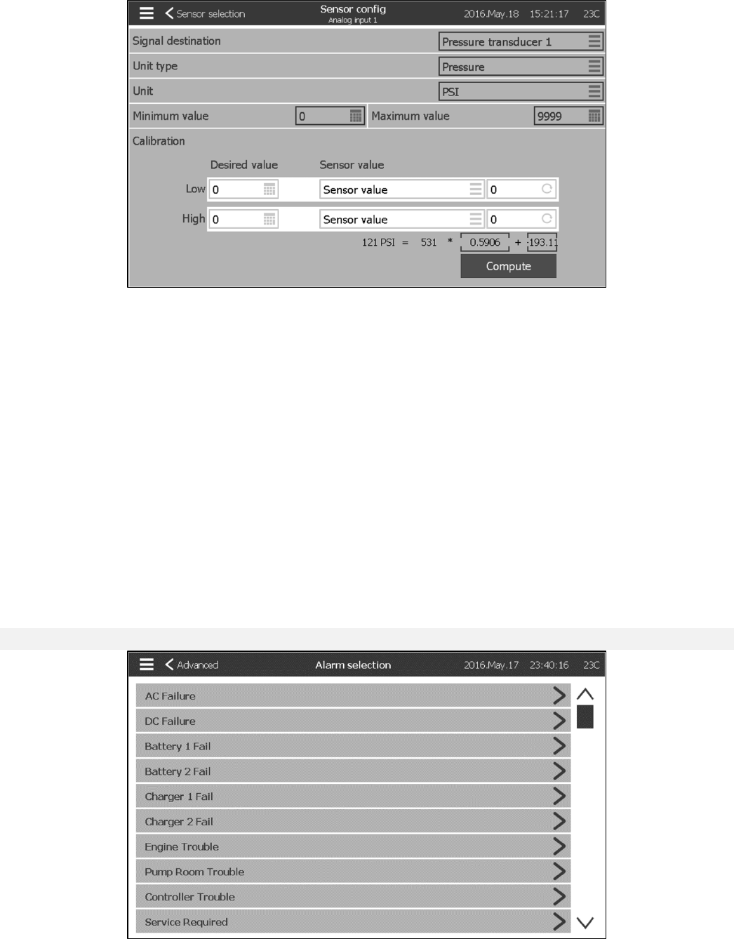
Sensor Selection
Config > Advanced > Sensors
Five analogue sensors, an AC voltage sensor, two battery current sensors and two battery voltage sensors can be
calibrated by accessing this page. The Analogue Input 1 is dedicated to the Pressure Transducer. The other Analog
Input depends on the controller options.
34
Every sensor, except the AC Voltage can be calibrated the same way. The Signal destination, the Unit type, the
Unit, the Min and Max value are variables that are set in factory but the calibration can be made in the field.
There are three ways of calibrating a sensor that can be chosen in the windows below “Sensor value”.
-Sensor value: Use an external mean of measurement that is already calibrated. Bring the sensor to a low value
and take a measurement with the calibrated instrument. Enter that value in the “Low” window below the “Desired
value” and press the window on the right (with the circular arrow). Repeat with a higher value of the sensor. Then
press compute.
-Theorical voltage: Use a graphic of the theorical sensor’s voltage response (usually given in the datasheet of the
sensor). Enter a low point (value, voltage) and a high point. Then press compute.
-Theorical current: Same as the theorical voltage, but with amperes.
For better results, use two points that are far apart, but in the normal range of the sensor.
For the AC voltage, only one point is needed.
Alarms
Config > Advanced > Alarms
35
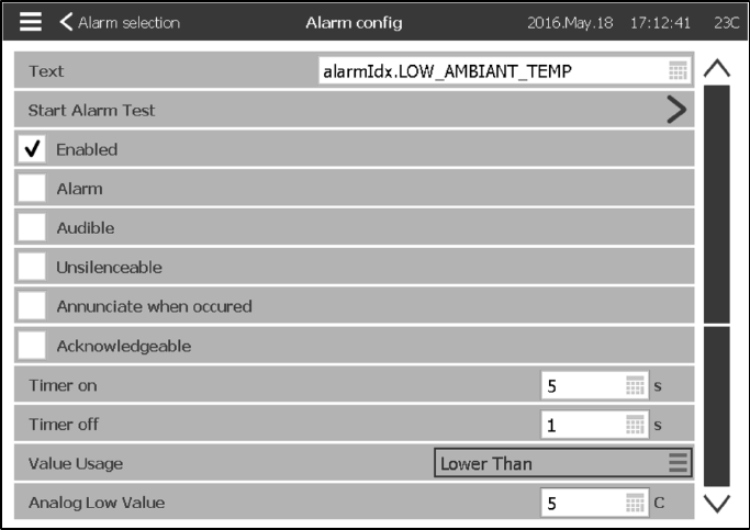
Most alarms are not configurable in the field, but some are with the appropriate password level. If it’s configurable,
the boxes will be in white. Otherwise the boxes will be grey. Also, the two last fields: Value Usage and Analog Value
are not always visible.
Text: This field can be used to change the name of the alarm that will be displayed while this alarm is active.
Start Alarm Test: The alarm can be tested using this button.
Enable: Check this box to enable the Alarm and to make this signal an alarm (red display). Otherwise, it will be a
warning (yellow display).
Audible: Check this box to make the bell ring while this alarm is active.
Unsilenceable: Check this box to make the bell unsilenceable while the alarm is active.
Annunciate when occurred: Check this box to create a new state for the alarm. After it has been “Active”, the alarm
will appear as “Occurred” in the alarm list when the condition triggering the alarm is no longer present.
Acknowledgeable: Check this box to make the alarm acknowledgeable. If an alarm is ackowledged, the bell will be
silenced and the alarm IO board Output will stop being active. To acknowledge an alarm, go to the alarm list page
and press the blue “Active” status on the right of the alarm. The “Active” status should change to “Acknowledge”.
Press again on the status to return to “Active”.
Timer on: It is the time delay between the triggering of the condition and the activation of the alarm.
Timer off: It is the time delay between the stoping of the condition and the deactivation of the alarm.
Value Usage, Analog Value: It is used to describe the activation range of the alarm. “Lower Than”, “Higher Than”
and “Between” can be selected. The coresponding value has to be entered.
36
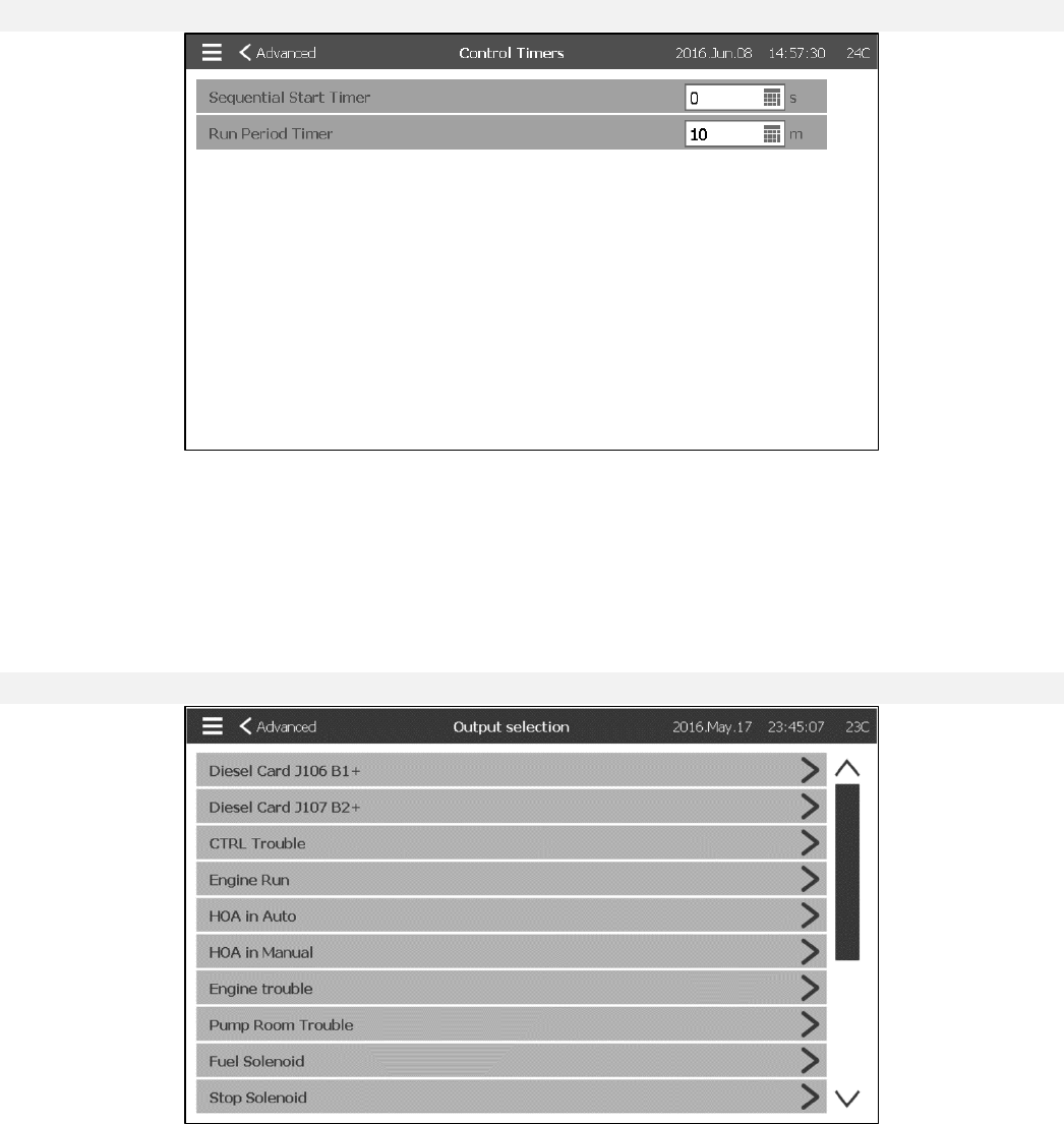
Control Timers
Config > Advanced > Control Timers
This page is used to adjust the timers.
- Sequential Start Timer: The time delay between a demand becoming active and the starting of the engine.
(Optional)
- Run Period Timer: The time the motor will keep running after the demand is resolved.
Outputs
Config > Advanced > Outputs
This page is used to choose the logic of the signals that will activate the Outputs on the IO board and to test those
Outputs.
- Diesel Card (J106 B1+)
- Diesel Card (J107 B2+)
- CTRL Trouble (TB1)
- Engine Run (TB2)
- HOA in OFF (TB3)
- HOA in Manual (TB4)
- Engine Trouble (TB5)
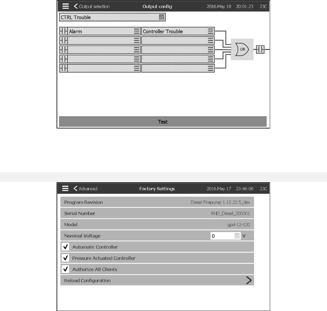
37
- Pump Room Trouble (TB6)
- Fuel Solenoid (1)
- Stop Solenoid (12)
- Contactor 1 (9)
- Contactor 2 (10)
- Test Solenoid Valve
- Alarm Bell
Pressing on an Output will lead to this page:
The first box from the top is used to change the name of the Output. For the output’s logic, a combination of 5 digital
inputs can be selected. Each input can be an alarm or a signal from a list and can be inverted by pressing the
NO/NC contact symbol at the left of the screen. A logical AND or OR can combine the chosen inputs and the exit
can also be inverted by pressing pressing the NO/NC contact symbol at the right of the screen.
Factory Settings
Config > Advanced > Factory Settings
This page is used to visualize and modify the Factory Settings. The Program Revision, the Serial Number, the
Model and the Nominal Voltage can be visualized.
- Automatic Controller: Uncheck this box to make the controler non-automatic. This means that the engine can only
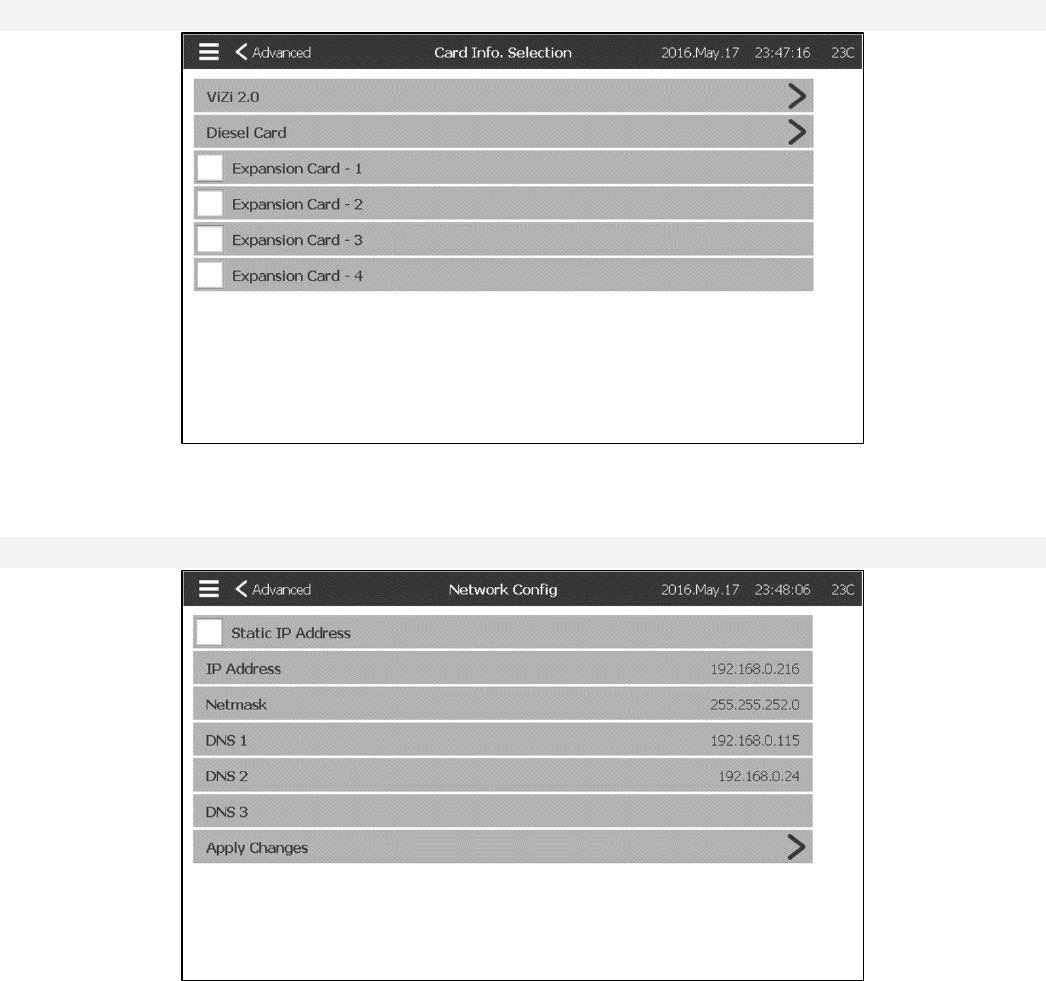
38
be started with the manual crank pushbutton on the ViziTouch and with the “remote manual” function.
- Pressure Actuated Controller: Uncheck this box to make the controller non-pressure actuated. This means that the
pressure transducer is no longer a starting cause of the engine.
- Authorize All Clients: Whenever someone is trying to gain remote access to the controller via the WebVizu, an
authorization has to be made locally from the ViziTouch. If this box is checked, no authorization does not need to be
made.
IO Card Info
Config > Advanced > IO Card Info
This page is used to visualize the Vizitouch and the Diesel IO card registers by pressing on the blue arrows on the
right of the screen. Expansion Cards can also be installed via this page.
Network
Config > Advanced > Network
This page displays the IP address, the Netmask and the DNS1-2-3 of the controller. The IP address can also be
made Static by checking the box on the upper left corner. To apply the change, press on the blue arrow in the
bottom right corner.
39
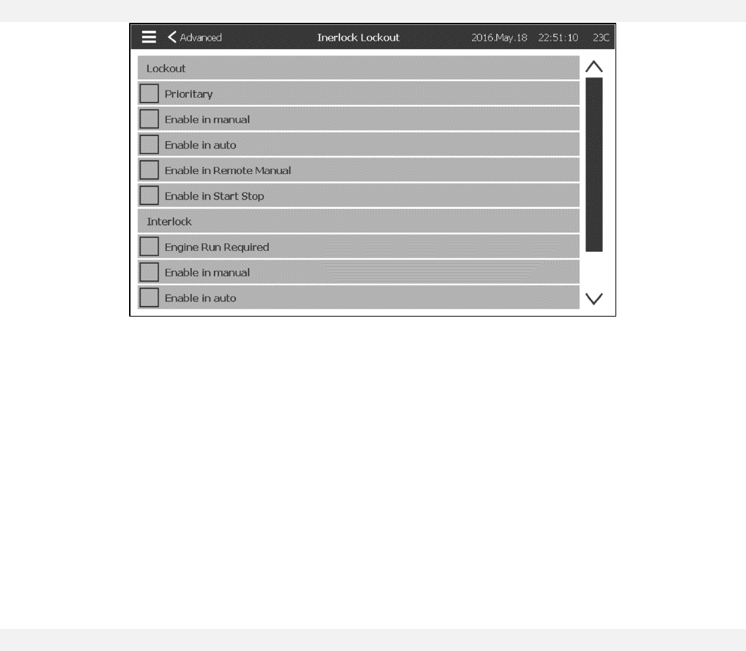
Interlock Lockout
Config > Advanced > Interlock Lockout
This page is used to configure the Lockout output and the Interlock input parameters. To be active those options
need to be assigned to an Input or an Output on the IO board.
Lockout is an Input that disables the engine from starting.
-Priority: If enabled, the lockout signal will also act as a shutdown.
-Enable in manual: If checked, this option will prevent the Manual start.
-Enable in auto: If checked, this option will prevent the Automatic start.
-Enable in Remote Manual: If checked, this option will prevent the Remote Manual start.
-Enable in Start Stop: If checked, this option will prevent the Start Stop mode.
Interlock is an Output that prevents a second motor from starting.
-Engine Run Required: If enabled, the controller will wait to have Engine Run before putting Interlock Active.
-Enable in manual: If checked, this option will activate the output Interlock on a Manual start.
-Enable in auto: If checked, this option will activate the output Interlock on a Automatic start.
-Enable in Remote Manual: If checked, this option will activate the output Interlock on a Remote Manual start.
-Enable in Start Stop: If checked, this option will activate the output Interlock on a Start Stop mode.
Reboot ViziTouch
Config > Advanced > Reboot Vizitouch
If this button is pressed, the ViziTouch will reboot. All unsave changed will be lost.
40
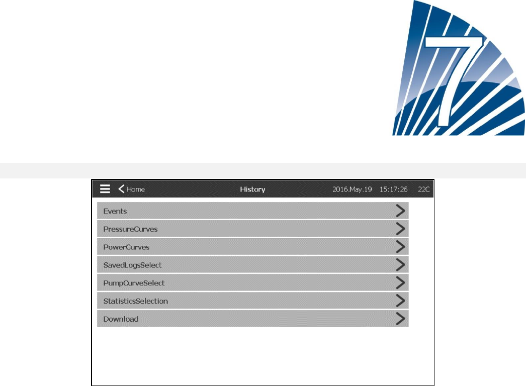
History
History (Menu)
History
This page is used to access all data related to events, statistics, pressure history, power logs and the downloading
of this information via one of the two USB ports.
-Events: This button leads to the “Events” page, which displays the most recent 500 events. Each event log
contains the date and time of occurrence as well as a brief description of the event.
-Pressure/Power Curves: This button leads to the “Pressure Curves” / “Power Curves” page accordingly, which
displays all relevant pressure/power information.
-SavedLogsSelect: This button leads to a page where past logs can be viewed.
-PumpCurveSelect: This button leads to the “Pump Curves” page.
-StatisticsSelection: This button leads to the “StatisticsSelection” page, which leads to “All Time Statistics”, “First
Service Statistic” and “Last Service Statistics” pages.
-Download: This button leads to the “Download” page, which allows the user to download information, including the
user manual, drawings, logs, statistics and configuration.
41
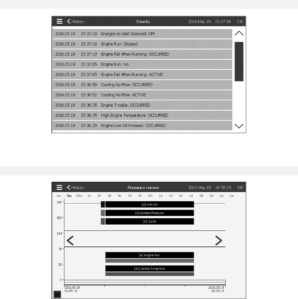
Events Page
History > Events
The Events Page shows the last events which occurred in chronological order. The last 500 Log Events are
displayed. The first column is the date, the second one is the time of occurrence and the third column is the “Event
message”. To obtain a log that is older than thoses events, visit the “SavedLogsSelect”.
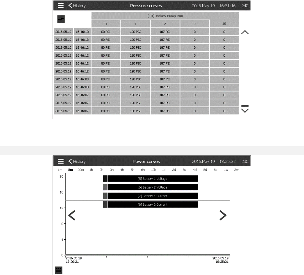
Pressure Curves
History > PressureCurves
On this page, a graphic of the “System Pressure”, the “Cut-in”, the “Cut-Out”, the main pump “Engine Run” and the
“Jockey Pump Run” through time can be viewed. By pressing on the srceen, the caption will diseapere or will be
displayed. The time scale can be changed by pressing the time span desired on top of the screen (from 1 minute to
2 weeks). The blue arrows on both sides of the graphic are used to navigate through time. The blue button in the
bottom left corner leads to the table used to generate this graph.
42
This table allows viewing of the exact values used to generate the Pressure Curves with the precise time. Pressing
the blue button on the top left corner will return to the graph page.
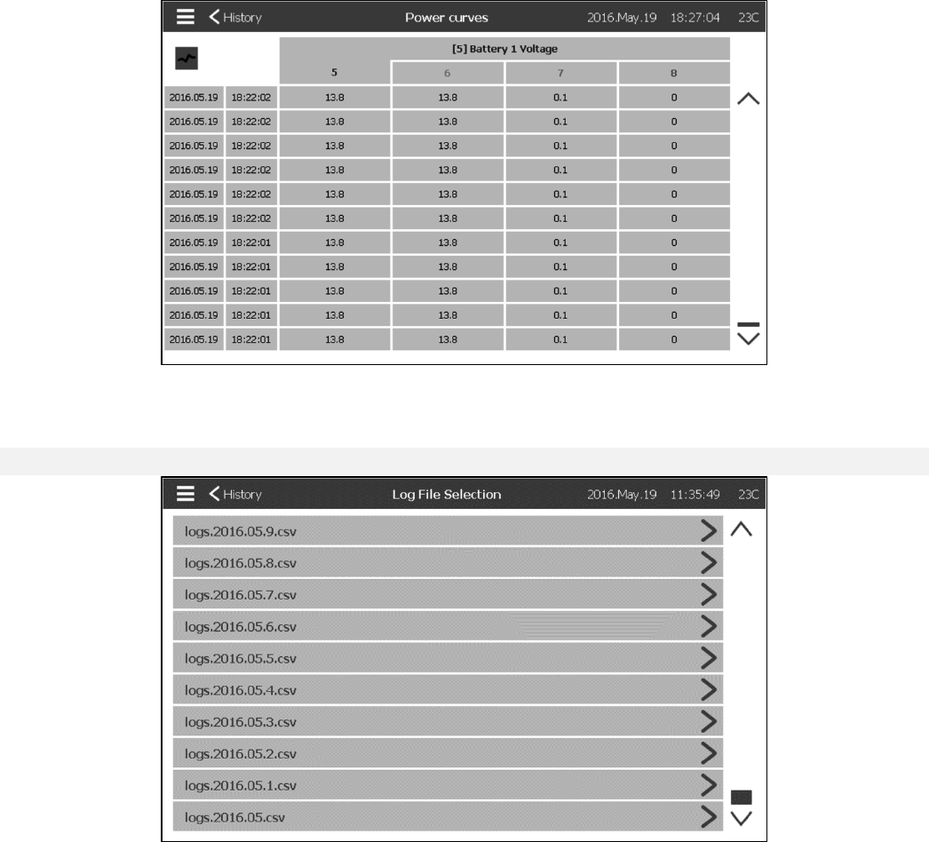
Power Curves
History > Power Curves
On this page, a graphic of the “Battery 1 Voltage”, the “Battery 2 Voltage”, the “Battery 1 Current” and the “Battery 2
Current” through time can be viewed. By pressing on the srceen, the caption will diseaper or will be displayed. The
time scale can be changed by pressing the time span desired on top of the screen (from 1 minute to 2 weeks). The
blue arrows on both sides of the graphic are used to navigate through time. The blue button in the bottom left corner
leads to the table used to generate this graph.
43
This table allows to viewing of the exact values used to generate the Power Curves with the precise time. Pressing
the blue button on the top left corner will return to the graph page.
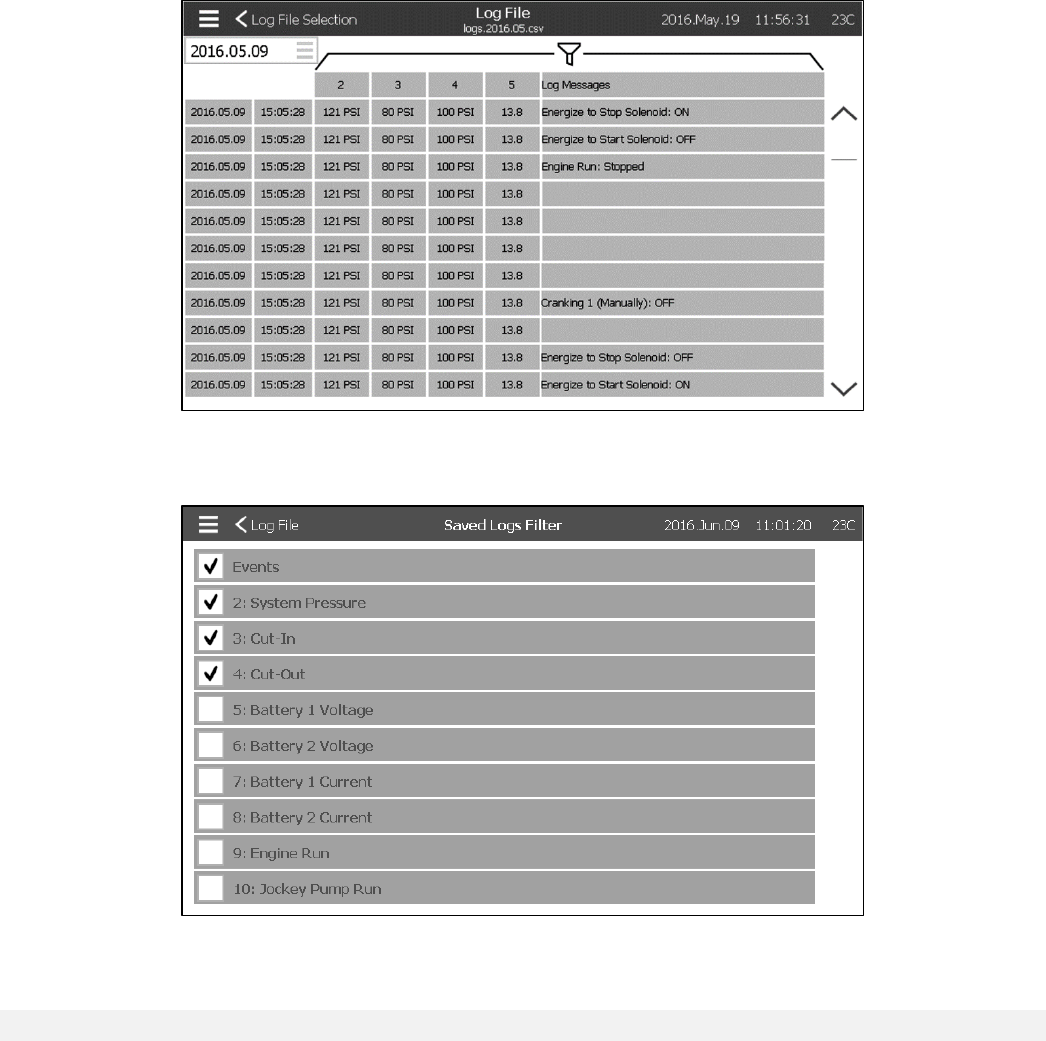
Saved Logs Select
History > SavedLogsSelect
This page is used to access every past log files. Each log file is a CSV file containing the time, the date, the Cut-in,
the Cut-out, the system pressure, the battery voltages and currents, the engine run signal, the jockey pump run
signal and the log event message. Each file can contain 1 MB of data and the month and year is integrated in it’s
title. Each time a CSV file is full, a new one is created with an incremented number in the title. Press on the file to
consult it’s content.
44
The logs are aranged chronologicaly. To select the displayed data, press on the filter icon in the center top of the
screen.
From this page, the selected values will be displayed. Press on “Log File” at the top left of the screen to go back to
the logs table.
Pump Curve Selection
History > PumpCurveSelect
This page is intended to help the customer generate the pump performance curve of the pump. In Auto mode, the
controller will sampled the water flow exiting the pump, the system pressure and the suction at the entrance of the
pump. The right sensor has to be installed for this mode to work. Each time the variation of a variable is important
enough, the controller will record the values and ring the bell. In manual mode, the user can enter manualy the
values to generate the pump curve.
45
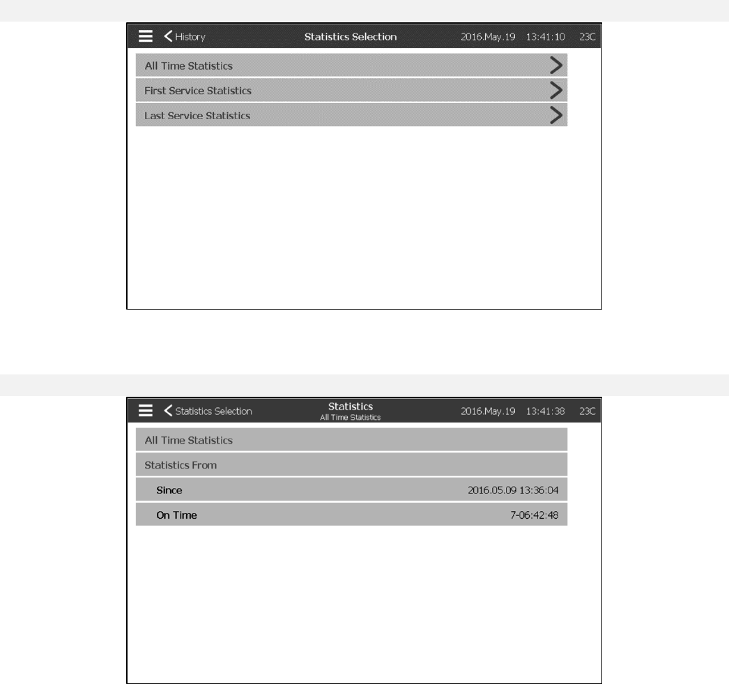
Statistic selection
History > Statistics Selection
This page leads to 3 other Statistics pages: “All Time Statistics”, “First Service Statistics” and “Last Service
Statistics”.
All Time Statistics
History > Statistics Selection > All Time Statistics
The “All Time Statistics” contains two parameters: The date the controller has been powered for the first time and
the amount of time it’s been ON for.
46
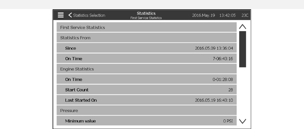
First Service Statistics
History > Statistics Selection > First Service Statistics
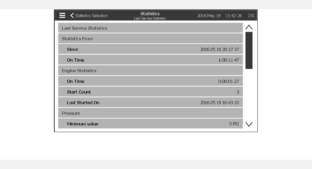
This page allows the user to view the “First Setup Statistics”. The parameters are:
Statistics From:
- Since: Date of the first setup
- ON Time: Time the controller spent ON, in DAYS-HOURS:MINUTES-SECONDS
Engine Statistics:
- ON Time: Time the engine spent ON, in DAYS-HOURS:MINUTES-SECONDS
- Start Count: Number of times the engine has started
- Last Started on: Last time the engine started
Pressure
- Minimum value: Smallest pressure value
- Minimum occurred: on Date the smallest value happened
- Maximum: Biggest pressure value
- Maximum occurred on: Date the biggest value happened
- Average Value: Average pressure since first startup
Temperature
- Minimum value: Smallest temperature value
- Minimum occurred on: Date the smallest value happened
- Maximum: Biggest temperature value
- Maximum occurred on: Date the biggest value happened
- Average Value: Average temperature since first startup
Jockey Pump Running
- ON Time: Time the Jockey Pump spent ON, in DAYS-HOURS:MINUTES-SECONDS
- Start Count: Number of times the Jockey Pump has started
- Last Started on: Last time the Jockey Pump started
47
Last Service Statistics
History > Statistics Selection > Last Service Statistics
This page allows the user to view the “Last Setup Statistics”. The parameters are the same as the ones from the
“First Setup Statistics” page but from the “Last Service”.
Download
History > Statistics Selection > Download
This page is used to download Statistics, PCB informations, name plate information, logs, the manual, the factory
settings and the current settings. A USB key needs to be inserted in the USB slot prior to entering this page in order
to be able to download.

48
Language
The language displayed on the ViZiTouch can be selected on this page.
49
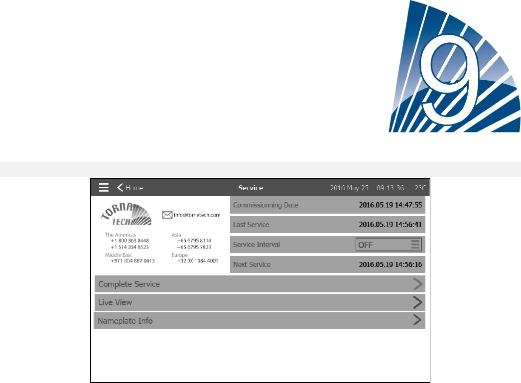
Service
Service
Information on how to reach Tornatech support can be viewed on this page. Also, information on the commissioning
date, on the last service date and on the next service due date is available. The service interval can be selected
from these options: OFF, ½ year, 1 year, 1 ½ years, 2 years and 3 years. The next service will be determined using
the last service and the chosen sevice interval.
The “Complete Service” will be available only by the authorized person after a service is completed.
The “Live View” page is where the user can grant or refuse the remote access demands.
The “Nameplate Info” page contains all the information found on the nameplate.

50
Manuals
This section is used to access a simplified version of the Manual. Select a language to have access to the chapters.
Select a chapter to consult it.

51
Technical Documents
How to Test:
Charger 1 Fail
Switch Circuit breaker 1 (CB1) in Off position.
Charger 2 Fail
Switch Circuit breaker 1 (CB2) in Off position.
DC Failure
Switch Circuit Breaker 3 (CB3) and Circuit Breaker 4 (CB4) in Off position or disconnect #6 and #8 engine wires
(See drawing for more details).
Faulty Pressure Transducer
Disconnect the Pressure Transducer. Depending of your sensor type, put a jumper between positive pin (left) or
negative pin (right) and signal pin (middle) of this connector (See drawing for more details).
Weekly Test Check Solenoid Valve
Disconnect the Solenoid Valve. Switch the HOA selector switch to the Auto position. Press the Run Test button
(Yellow button on the membrane). Wait until the test ends. (Note: The engine will start.)
Controller Trouble
To activate this common alarm, at least one of the following alarms must be active: Charger Failure 1, Charger
Failure 2, DC Failure, Faulty Pressure Transducer or Weekly Test Check Solenoid Valve.
Low Fuel Level
Put a jumper between Low Fuel Level input and ground (See drawing for more details).
High Fuel Level
Put a jumper between High Fuel Level input and ground (See drawing for more details).
Fuel Tank Leak
Put a jumper between Fuel Tank Leak input and ground (See drawing for more details).
AC Failure
Make sure both batteries are connected and all circuit breakers are in the ON position. Switch the disconnect switch
to "OFF" position.
Low Ambient Temperature
You need to be logged in to modify these settings. Go to Config>Advanced>Alarms>Low Ambiant Temp. Change
the Low Ambiant Temperature setpoint to maximum allowable.
High Ambient Temperature
You need to be logged in to modify these settings. Go to Config>Advanced>Alarms>High Ambiant Temp. Change
52
the High Ambiant Temperature setpoint to the minimum allowable.
Low Suction Pressure
Disconnect Suction Pressure connector. Depending of your sensor type, put a jumper between positive pin (left) or
negative pin (right) and signal pin (middle) of this connector (See drawing for more details). Start the engine.
Water Reservoir Empty
Put a jumper between Water Reservoir Empty input and ground (See drawing for more details).
High Water Level
Put a jumper between High Water Level input and ground (See drawing for more details).
Water Reservoir Low
Put a jumper between Water Reservoir Low input and ground (See drawing for more details).
Pump Room Alarm
To activate this common alarm, at least one of the following alarms must be active: Low Fuel Level, High Fuel
Level, Fuel Tank Leak, AC Fail, Low Ambient Temperature, High Ambient Temperature, Low Suction Pressure,
Water Reservoir Empty, High Water Level or Water Reservoir Low.
Fail to Start
Disconnect #1, #9, #10 and #12 engine wires (See drawing for more details). Start the cranking sequence
(Example: Remove Remote Automatic Start jumper). Wait until the cranking sequence ends.
Overspeed
If your engine has an overspeed switch, switch it to the ON position. If not, disconnect #3 engine wire (See drawing
for more details) and put a jumper between #3 and #6. (Note: You don't need to start the engine to activate this
alarm.)
Electronic Control Module Selector Switch in Alternate Position (301)
Disconnect #301 engine wire. Put a jumper between #301 input and ground (See drawing for more details).
Fuel Injection Malfunction (302)
Disconnect #302 engine wire. Put a jumper between #302 input and ground (See drawing for more details).
Electronic Control Module Warning ( 303 )
Disconnect #303 engine wire. Put a jumper between #303 input and ground (See drawing for more details).
Electronic Control Module Fault ( 304 )
Disconnect #304 engine wire. Put a jumper between #304 input and ground (See drawing for more details).
Low Engine Temperature (312)
Disconnect #312 engine wire. Put a jumper between #312 input and ground (See drawing for more details).
Low Oil Pressure
Disconnect #4 engine wire (See drawing for more details). Put a jumper between #4 and ground. Start the engine.
High Engine Temperature
Disconnect #5 engine wire (See drawing for more details). Put a jumper between #5 and ground. Start the engine.
Battery 1 Failure
Disconnect #6 engine wire (See drawing for more details) and disconnect Charger CB.
Weak Battery 1
You need to be logged in to modify these settings. Go to Config>Advanced>Alarms>WeakBattery1. Change the
Weak Battery 1 setpoint to the maximum allowable.
Battery 2 Failure
Disconnect #8 engine wire (See drawing for more details) and disconnect Charger CB.
53
Weak Battery 2
You need to be logged in to modify these settings. Go to Config>Advanced>Alarms>WeakBattery2. Change the
Weak Battery2 setpoint to the maximum allowable.
Battery 1 Overvoltage
You need to be logged in to modify these settings. Go to Config>Advanced> Alarms>Battery1Overvoltage. Change
the Overvoltage Battery 1 setpoint to the minimum allowable.
Battery 2 Overvoltage
You need to be logged in to modify these settings. Go to Config>Advanced> Alarms>Battery2Overvoltage. Change
the Overvoltage Battery 2 setpoint to the minimum allowable.
Loss of Continuity 1
Disconnect #9 engine wire (See drawing for more details). Wait 1-2 minutes.
Loss of Continuity 2
Disconnect #10 engine wire (See drawing for more details). Wait 1-2 minutes
Underpressure
You need to be logged in to modify these settings. Go to Config>Advanced> Alarms>Underpressure. Change the
Underpressure setpoint to the maximum allowable.
Overpressure
You need to be logged in to modify these settings. Go to Config>Advanced> Alarms>Overpressure. Change the
Overpressure setpoint to the minimum allowable.
Low Pneumatic Pressure
Put a jumper between the Low Pneumatic Pressure input and ground (See drawing for more details). Take note
that this alarm will stop the pneumatic cranking sequence.
Engine Trouble
To activate this common alarm, at least one of the following alarms must be active: Fail to start, Overspeed,
Electronic Control Module Selector Switch in Alternate Position (301), Fuel Injection Malfunction (302), Electronic
Control Module Warning (303), Electronic Control Module Fault (304), Low Engine Temperature (312), Low Oil
Pressure, High Engine Temperature, Battery 1 Failure, Battery 2 Failure, Loss of Continuity 1, Loss of Continuity 2,
Overpressure or Low Pneumatic Pressure
Low Spare Temperature
Disconnect the Spare Temperature connector. Depending of your sensor type, put a jumper between positive pin
(left) or negative pin (right) and signal pin (middle) of this connector (See drawing for more details).
WT CI Not Reached
You need to be logged in to modify these settings. Go to the Config page. Change Cut-In to 0. Press Run Test
button (Yellow button of the membrane). Wait until the test ends.
Flow Start
Put a jumper between the Flow Start input and ground (See drawing for more details).
Cooling No Flow
Put a jumper between the Cooling No Flow input and ground (See drawing for more details).
Flow Meter On
Put a jumper between the Flow Meter On input and ground (See drawing for more details).
Engine Fail When Running
Start the engine. Depending of your engine type, disconnect #1 or put a jumper between #12 and #6 to stop the
54
engine. (See drawing for more details).
IO Diesel Communication Error
Press Reset button of the Diesel IO Board (Small button close to the phone jack)
IO Expansion 1 Communication Error
Press the Reset button of the Expansion 1 IO Board (Small button close to the phone jack)
IO Expansion 2 Communication Error
Press the Reset button of the Expansion 2 IO Board (Small button close to the phone jack)
IO Expansion 3 Communication Error
Press the Reset button of the Expansion 3 IO Board (Small button close to the phone jack)
IO Expansion 4 Communication Error
Press the Reset button of the Expansion 4 IO Board (Small button close to the phone jack)
Low Pump Room Temperature
Put a jumper between Low Pump Room Temperature input and ground (See drawing for more details).
Main Relief Valve Open
Put a jumper between Main Relief Valve Open input and ground (See drawing for more details).
Pump on Demand
Open the pressure line to simulate a pressure drop. The engine will start and the Pump On Demand warning will
appear.
Invalid Cut-In
You need to be logged in to modify these settings. Go to the Config page. Change the Cut-In to 0. (Note: The
engine will start.)
Pneumatic Fail to Start
Disconnect the TB6 relay connector. Disconnect #1, #9, #10 and #12 engine wires (See drawing for more details).
Start cranking sequence (Example: Remove Remote Automatic Start jumper). Wait until cranking sequence ends.
Hydraulic Fail to Start
Disconnect the TB6 relay connector. Disconnect #1, #9, #10 and #12 engine wires (See drawing for more details).
Start cranking sequence (Example: Remove Remote Automatic Start jumper). Wait until cranking sequence ends.

55
TORNATECH MODEL GPD DIESEL FIRE PUMP CONTROLLER
PRE- FIELD ACCEPTANCE TEST
CHECK LIST
Note: This document should be an official indication of whether or not the installation and general condition
of the equipment is adequate for a field acceptance test. This document should also aid the individual
responsible for executing the field acceptance test in his decision to carry out or not the field acceptance
test of the equipment.
Installation Check List:
YES
NO
1
Verify that the nameplate voltages of the Fire Pump Controller corresponds with the AC
voltage available and the DC starting voltage of the engine.
2
Visual inspection for any damage to the exterior of the Fire Pump Controller. Make sure
the enclosure, alarm bell, selector switch, membrane and display are not damaged.
3
Verify that the Fire Pump Controller has been installed within sight of the pump and
engine.
4
Verify that the Fire Pump Controller has been installed not less than 12 inches from the
floor of the mechanical room.
5
Verify that all electrical connections to the Fire Pump Controller are done using liquid
tight conduit and connectors.
6
With the Fire Pump Controller door open, visually inspect for any drill chips, dirt or
foreign objects in the bottom of the enclosure, loose wires, broken components and
general proper electrician workmanship.
7
Verify that the correct AC voltage is supplied to the controller by taking a voltage
reading at the L1 & N (120V) or L1 & L2 (220-240) terminals.
8
Verify that the terminal connections between the Fire Pump Controller and the engine
(1 to 11 and 12 for Caterpillar engines) are properly done (optionally
301,302,303,304,305,310,311,312).
9
Verify that wiring to terminals #6, #8 (batteries) and #11 (ground) are of the appropriate
gauge size. See label inside controller.
10
Verify proper grounding of the Fire Pump Controller.
Initial Power-Up Check List:
YES
NO
1
Verify the selector switch is in the “OFF” position
2
With the Fire Pump Controller door open, turn to “ON” circuit breakers CB3 and CB4
(DC) then CB1 and CB2 (AC), then DS1. This sequence is very important.
3
Close the Fire Pump Controller door. Verify on the ViZiTouch Homepage that the
correct battery voltage appears.
4
Place the selector switch in the “HAND” position. Verify that no alarms are displayed on
the screen.
5
Place the selector switch in the “AUTO” position. Verify that no alarms are displayed on
the screen.
Manual and Automatic Start Check List:
YES
NO
1
Place the selector switch in the “Hand” position.
2
Verify the starting of the engine by pressing the “Battery # 1 Manual Crank” membrane
button.
3
Stop engine by placing the selector switch to the “OFF” position.
4
Verify the starting of the engine by pressing the “Battery # 2 Manual Crank” membrane
button.
5
Stop engine by placing the selector switch to the “OFF” position.
6
Set the Cut-Out and Cut-In settings by following the quick start up guide or referring to
the ViZiTouch documentation. You need to be logged in to modify these settings. Verify
automatic start by dropping the system pressure below Cut-In setting.
7
Stop the engine by pressing the “Stop” pushbutton. Note: The engine will only stop if
the system pressure is above the Cut-Out setting.
Tornatech Controller S/N: _________________________________________
Installation address: _________________________________________
_________________________________________

56
_________________________________________
Check list completed? _____________Yes _____________ No
Check list completed by: __________________________________________
Company: __________________________________________
Date: __________________________________________
Witnessed By: __________________________________________
Comments: ___________________________________________________________________________
___________________________________________________________________________
___________________________________________________________________________
___________________________________________________________________________
___________________________________________________________________________
___________________________________________________________________________

57
TORNATECH MODEL GPD
DIESEL ENGINE FIRE PUMP CONTROLLER
FIELD ACCEPTANCE TEST REPORT
Note: This document is the Tornatech official Field Acceptance Test report which follows the latest NFPA 20
requirements of article 14.2.6 Controller Acceptance Test pertinent to diesel engine driven fire pump
controllers. Tornatech strongly recommends that a pre-field acceptance verification (Tornatech document
GPD-PREFAT-001-E Pre-Field Acceptance Test Check List) be completed before this official field acceptance
test.
Complete this first section if it was not completed during the Pre-Field Acceptance test
Manual and Automatic Start Check List:
YES
NO
1
Place the selector switch in the “Hand” position.
2
Verify the starting of the engine by pressing the “Battery # 1 Manual Crank”
membrane button.
3
Stop engine by placing the selector switch to the “OFF” position.
4
Verify the starting of the engine by pressing the “Battery # 2 Manual Crank”
membrane button.
5
Stop engine by placing the selector switch to the “OFF” position.
6
Set the Cut-Out and Cut-In settings by following the quick start up guide or referring
to the ViZiTouch documentation. You need to be logged in to modify these settings.
Verify automatic start by dropping the system pressure below Cut-In setting.
7
Stop the engine by pressing the “Stop” pushbutton. Note: The engine will only stop
if the system pressure is above the Cut-Out setting.
Battery # 1
YES
NO
1
3 manual starts
2
3 automatic starts
3
1 RUN TEST start
4
1 remote/deluge valve start
5
Start and Run the engine at full speed after 1 crank cycle
Battery # 2
YES
NO
1
3 manual starts
2
3 automatic starts
3
1 RUN TEST start
4
1 remote/deluge valve start
5
Start and Run the engine at full speed after 1 crank cycle
Visual/Audible Alarm Verification
YES
NO
1
Battery failure:
- At the terminal strip, turn CB1 OFF, disconnect wire #6 for battery #1. Then
reconnect wire 6 and put CB1 to ON.
- At the terminal strip, turn CB2 OFF, disconnect wire #8 for battery #2. Then
reconnect wire 8 and put CB2 to ON.
- Audible and visual alarm will appear for battery failure and controller trouble
Note: it is important to return the wires back to their original place and reset the
alarms in order to continue the tests.
2
Charger failure:
- Switch either circuit breaker #1 (CB1) or circuit breaker #2 (CB2) to the OFF
position to test either charger.
- Audible and visual alarm will appear for charger failure and controller trouble
Warning: Do not switch both CB1 and CB2 off at the same time.
Note: it is important to return the circuit breaker back to its original position and
reset the alarms in order to continue the tests.
3
Engine high coolant temperature:
- Start the engine either manually or automatically.
- With the engine running, place a jumper between terminals 5 & 11 or simulate

58
high coolant signal coming from the engine.
- If the engine was started manually, a visual and audible alarm will be present and
the engine will not shutdown. To shutdown, turn the selector switch to the OFF
position.
- If the engine was started automatically, a visual and audible alarm will be present
and the engine will not shutdown. To shutdown, turn the selector switch to the OFF
position.
- Note: Please remove the jumpers and reset the alarm in order to continue to the
next simulation.
4
Engine low oil pressure:
- Start the engine either manually or automatically.
- With the engine running, place a jumper between terminals 4 & 11 or simulate
engine low oil pressure from the engine. The alarm will annunciate after 8 seconds.
- If the engine was started manually, a visual and audible alarm will be present and
the engine will not shutdown. To shutdown, turn the selector switch to the OFF
position.
- If the engine was started automatically, a visual and audible alarm will be present
and engine will not shutdown. To shutdown, turn the selector switch to the OFF
position.
Note: Please remove the jumpers and reset the alarm in order to continue to next
simulation.
5
Engine Overspeed:
- Start the engine either manually or automatically.
- With the engine running, place a jumper between terminals 6 & 3 or simulate
overspeed from the engine.
- An audible and visual alarm will be present and the engine will shutdown whether
it was started manually or automatically.
Note: Please remove jumpers and reset the alarm in order to continue to next
simulation.
Note: The speed switch must be reset on the engine itself.
6
Engine fail to start:
- At the terminal strip, disconnect wires #9 and #10
- Place the controller selector switch to Auto and initiate automatic engine start or
start engine by pressing the Run Test Button
The controller will go through its cranking cycle as follows:
- 15 second cranking from battery #1
- 15 second rest
- 15 second cranking from battery #2
- 15 second rest
- This cycle will repeat itself three times per battery, hence six times.
- Audible and visual alarm for engine fail to start will appear.
- Switch the engine control panel back to OFF position and reset the alarm.
7
Stop the engine by pressing the “Stop” pushbutton. Note: The engine will only stop
if the system pressure is above the Cut-Out setting.
Field Settings:
Cut-Out Pressure: ________
Cut-In Pressure: ________
Minimum run period timer activated?
Yes: _____ Set at _____minutes. No: _____
Sequential Start Timer?
Yes: _____ Set at _____seconds. No: _____

59
Weekly Test Enabled?
Yes: _____ Start (date and time) ___________ No: _____
Stop (date and time) ___________
Alarm Contacts Connections:
Selector switch in OFF or HAND connected? _____Yes _____ No
Engine Run connected? _____Yes _____ No
Engine Trouble connected? _____Yes _____ No
Controller Trouble connected? _____Yes _____ No
Other contacts supplied and connected?
Yes: _______________________________________________________
No: _____
Tornatech Controller S/N: _________________________________________
Installation address: _________________________________________
_________________________________________
Field Acceptance Test completed? _____Yes _____ No
Field Acceptance completed by: __________________________________________
Company: __________________________________________
Date: __________________________________________
Witnessed By: __________________________________________
Company: __________________________________________
The undersigned witness has been made aware of the NFPA20 article 14.4 Periodic Inspection, Testing and
Maintenance which stipulates that “Fire pumps shall be inspected tested and maintained in accordance with NFPA25
– Standard for the Inspection, Testing and Maintenance of Water Based Fire Protection Systems”
Comments: _____________________________________________________________________________
_____________________________________________________________________________
_____________________________________________________________________________
_____________________________________________________________________________
_____________________________________________________________________________

60
#######