TP Link Technologies AP300 AC1200 Wireless Gigabit Access Point User Manual
TP-Link Technologies Co., Ltd. AC1200 Wireless Gigabit Access Point Users Manual
Users Manual

REV1.0.0 1910011495
AP300
User Guide
AC1200 Wireless Gigabit Access Point
Contents
About This Guide ...............................................................................................1
Chapter 1. Get to Know About Your AP Device . . . . . . . . . . . . . . . . . . . . . . 2
1. 1. Product Overview . . . . . . . . . . . . . . . . . . . . . . . . . . . . . . . . . . . . . . . . . . . . . . . . . . . . . . . . . . 3
1. 2. Main Features . . . . . . . . . . . . . . . . . . . . . . . . . . . . . . . . . . . . . . . . . . . . . . . . . . . . . . . . . . . . . . 3
1. 3. Panel Layout . . . . . . . . . . . . . . . . . . . . . . . . . . . . . . . . . . . . . . . . . . . . . . . . . . . . . . . . . . . . . . . 4
1. 3. 1. Top View. . . . . . . . . . . . . . . . . . . . . . . . . . . . . . . . . . . . . . . . . . . . . . . . . . . . . . . . . . . . . 4
1. 3. 2. The Back Panel . . . . . . . . . . . . . . . . . . . . . . . . . . . . . . . . . . . . . . . . . . . . . . . . . . . . . . . 5
1. 4. Position Your AP Device . . . . . . . . . . . . . . . . . . . . . . . . . . . . . . . . . . . . . . . . . . . . . . . . . . . . 6
Chapter 2. Operation Modes. . . . . . . . . . . . . . . . . . . . . . . . . . . . . . . . . . . . . . . 7
2. 1. Determine the Mode . . . . . . . . . . . . . . . . . . . . . . . . . . . . . . . . . . . . . . . . . . . . . . . . . . . . . . . 8
2. 2. Connect Your AP Device . . . . . . . . . . . . . . . . . . . . . . . . . . . . . . . . . . . . . . . . . . . . . . . . . . . . 8
Chapter 3. Log into Your AP Device . . . . . . . . . . . . . . . . . . . . . . . . . . . . . . . 10
Chapter 4. Set Up Wireless Connections . . . . . . . . . . . . . . . . . . . . . . . . . . . 13
4. 1. Quick Setup. . . . . . . . . . . . . . . . . . . . . . . . . . . . . . . . . . . . . . . . . . . . . . . . . . . . . . . . . . . . . . . 14
4. 2. WPS . . . . . . . . . . . . . . . . . . . . . . . . . . . . . . . . . . . . . . . . . . . . . . . . . . . . . . . . . . . . . . . . . . . . . . 16
4. 3. Manually set up a wireless connection . . . . . . . . . . . . . . . . . . . . . . . . . . . . . . . . . . . . . 18
4. 4. Check the connection status. . . . . . . . . . . . . . . . . . . . . . . . . . . . . . . . . . . . . . . . . . . . . . . 24
Chapter 5. Customize Your Network and Security Settings. . . . . . . . . . 25
5. 1. Change the LAN Settings . . . . . . . . . . . . . . . . . . . . . . . . . . . . . . . . . . . . . . . . . . . . . . . . . . 26
5. 2. Specify DHCP Server Settings . . . . . . . . . . . . . . . . . . . . . . . . . . . . . . . . . . . . . . . . . . . . . . 26
5. 3. MAC Filtering . . . . . . . . . . . . . . . . . . . . . . . . . . . . . . . . . . . . . . . . . . . . . . . . . . . . . . . . . . . . . 28
5. 4. Advanced Wireless Settings. . . . . . . . . . . . . . . . . . . . . . . . . . . . . . . . . . . . . . . . . . . . . . . . 30
Chapter 6. Manage Your AP Device . . . . . . . . . . . . . . . . . . . . . . . . . . . . . . . 33
6. 1. System Log . . . . . . . . . . . . . . . . . . . . . . . . . . . . . . . . . . . . . . . . . . . . . . . . . . . . . . . . . . . . . . . 34
6. 2. Test the Network Connectivity . . . . . . . . . . . . . . . . . . . . . . . . . . . . . . . . . . . . . . . . . . . . . 34
6. 3. Upgrade the Firmware. . . . . . . . . . . . . . . . . . . . . . . . . . . . . . . . . . . . . . . . . . . . . . . . . . . . . 36
6. 4. Backup and Restore Configuration Settings . . . . . . . . . . . . . . . . . . . . . . . . . . . . . . . . 37
6. 5. Change the Management Account. . . . . . . . . . . . . . . . . . . . . . . . . . . . . . . . . . . . . . . . . 38
6. 6. Throughput Monitor . . . . . . . . . . . . . . . . . . . . . . . . . . . . . . . . . . . . . . . . . . . . . . . . . . . . . . 39
6. 7. Statistics . . . . . . . . . . . . . . . . . . . . . . . . . . . . . . . . . . . . . . . . . . . . . . . . . . . . . . . . . . . . . . . . . . 40
6. 8. SNMP Management . . . . . . . . . . . . . . . . . . . . . . . . . . . . . . . . . . . . . . . . . . . . . . . . . . . . . . . 40
6. 9. Ping Watchdog. . . . . . . . . . . . . . . . . . . . . . . . . . . . . . . . . . . . . . . . . . . . . . . . . . . . . . . . . . . . 41
6. 10. LEDs Control . . . . . . . . . . . . . . . . . . . . . . . . . . . . . . . . . . . . . . . . . . . . . . . . . . . . . . . . . . . . . . 42
FAQ .....................................................................................................................43
Specifications ...................................................................................................46
1
About This Guide
This guide provides details of each function and shows how to configure the AP device
appropriate to your needs. In addition to this guide, a Quick Installation Guide is also
released with each TP-LINK AP device, you are suggested to configure your AP device
for quick Internet setup by following the published Quick Installation Guide before you
get started with a further configuration.
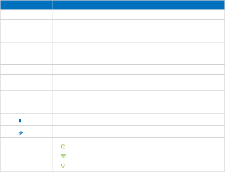
Conventions
In this guide the following conventions are used:
Convention Description
AP device Stands for 11AC Wireless Gigabit Access Point without any explanation.
parameters
Parameters provided in the screenshots are just references for setting up the device,
which may differ from the actual situation. You can set the parameters according to
your demand.
screenshots
The demonstrated screenshots may look a little different from the actual web page of
your device due to the various firmware versions. Please just configure your product
based on the actual web page.
Blue Italic Hyperlinks are in blue italic. You can click to redirect to a website or a specific section.
Blue Contents to be emphasized and texts on the web page are in blue, including the
menus, items, buttons, etc.
>
The menu structures to show the path to load the corresponding page. For example,
Advanced > Wireless > WPS means the WPS function page is under the Wireless menu
that is located in the Advanced tab.
Note: Ignoring this type of note might result in a malfunction or damage to the device.
Tips: Indicates important information that helps you make better use of your device.
symbols on the web
page
• click to edit the corresponding entry.
• click to delete the corresponding entry.
• click to enable or disable the corresponding entry.


3
Chapter 1
1. 1. Product Overview
What This Product Does
The TP-LINK Wireless AC Access Point is designed to establish or expand a scalable high-
speed wireless AC network or to connect multiple Ethernet enabled devices such as
game consoles, digital media adapters, printers, or network attached storage devices
to a wireless network. The AP supports a host of different functions that make your
wireless networking experience more flexible than ever before. Now, you can enjoy a
better Internet experience when downloading, gaming or video streaming.
802.11ac - The Next Generation of Wi-Fi
TP-LINK’s Wireless AC Access Point comes with the next generation Wi-Fi standard -
802.11ac, backward compatible with 802.11n and 3 times faster than wireless N
speeds. With higher power efficiency and robust security, 802.11ac is the perfect way
to accelerate a home multimedia network and solve congestion that multiple devices
may cause.
Concurrent Dual Band - More Bandwidth, Less Interference
With the high wireless speeds over the crystal clear 5GHz band and the 2.4GHz band,
the Wireless AC Access Point offers you the flexibility of two dedicated networks and
ensures amazing wireless performance. Simple tasks such as sending e-mails or web
browsing can be handled by the 2.4GHz band while bandwidth intensive tasks like
online gaming or HD video streaming can be processed by the 5GHz band – all at the
same time.
Broad Wi-Fi Coverage and Targeted Connection
Featuring multiple detachable external antennas and high power amplifiers, the
Wireless AC Access Point is able to boost Wi-Fi coverage throughout your home.
Advanced Beamforming technology enables it to focus Wi-Fi signal on connected
devices, delivering a more targeted and highly efficient wireless connection.
Multiple Operating Modes - Easy to Build WLAN
Supports AP, Bridge/Repeater, Client and Multi-SSID operation modes to enable various
wireless applications to give you a more dynamic and comprehensive experience when
using the AP device. Multiple operating modes also helps you easily build wireless
network for hard-to-wire locations or eliminate wireless dead zone.
1. 2. Main Features
Wireless and Wired Performance
• Supports 802.11ac - The next generation of Wi-Fi, compatible with 802.11n
4
Chapter 1
• Support simultaneous 2.4GHz and 5GHz connections
• Multiple detachable external antennas and high power amplifiers provide stable
signals and optimal wireless coverage
• Up to 4 SSIDs and VLAN support
• Provides WPA/WPA2, WPA-PSK/WPA2-PSK authentication, TKIP/AES encryption
security
• Supports MAC filter, throughput monitor
• Easy one-touch WPA wireless security encryption with the WPS button
• Supports firmware upgrade and Web management
• Supports system log and Traffic Statistics
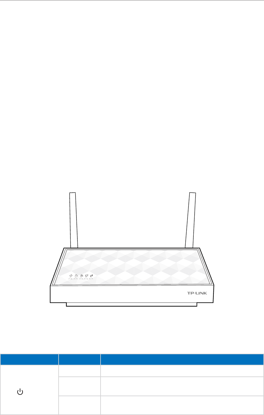
1. 3. Panel Layout
1. 3. 1. Top View
The AP device’s LEDs are located on the top panel. You can check the AP device’s
working status by following the LED Explanation table (view from left to right).
LED Explanation
Name Status Indication
(Power)
On System initialization completes.
Blinking System initialization or firmware upgrade is in process. Do not
disconnect or power off the AP device.
Off Power is off. Please ensure that the power adapter is connected
correctly.
5
Chapter 1
LED Explanation
Name Status Indication
(Wireless 2.4GHz)
On
The wireless 2.4GHz band is working properly (in AP/Multi-SSID
mode).
The host AP’s 2.4GHz network is selected (in Repeater/Bridge/Client
mode).
Off
The wireless 2.4GHz band is disabled (in AP/Multi-SSID mode).
The host AP’s 2.4GHz is not selected (in Repeater/Bridge/Client
mode).
(Wireless 5GHz)
On
The wireless 5GHz band is working properly (in AP/Multi-SSID mode).
The host AP’s 5GHz network is selected (in Repeater/Bridge/Client
mode).
Off The wireless 5GHz band is disabled (in AP/Multi-SSID mode).
The host AP’s 5GHz is not selected (in Repeater/Bridge/Client mode).
(LAN)
On A device is connected to the Ethernet port.
Off No device is connected to the Ethernet port.
(WPS)
Slow blinking WPS connection is in process.
On WPS connection is successful. It will turn off after 5 minutes.
Quick blinking WPS connection is failed.
Solid orange The signal strength is too weak (in Repeater/Bridge/Client mode).
Off The device is disconnected from the host network (in Repeater/
Bridge/Client mode).
Note:
After a device is successfully added to the network by WPS function, the WPS LED will keep on for about 5 minutes
and then turn off.
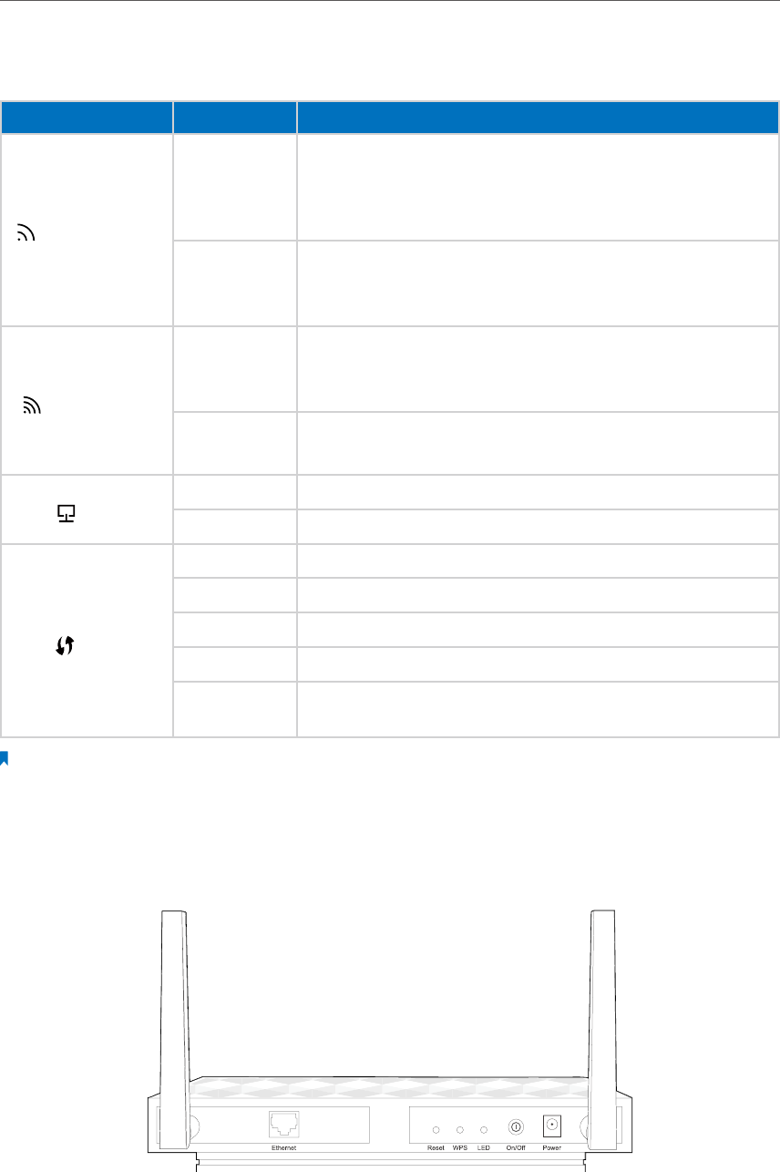
1. 3. 2. The Back Panel
The AP device’s back panel shows the connection ports, buttons and antennas. Refer to
the following for detailed instructions (view from left to right).
6
Chapter 1
Item Description
Ethernet One LAN 10/100/1000Mbps Auto-Negotiation RJ45 Port connects to a network device.
Reset
The switch for the reset function. With the device powered on, use a pin to press and
hold the Reset button for five seconds until the Power LED starts blinking, then release
the button.
WPS Press and hold this button for two seconds to enable the WPS function. When the WPS
LED blinks slowly, the device is trying to connect or to be connected.
LED Press this button to turn on or turn off the LEDs.
On/Off The switch for the power. Press it to power on or off the AP device.
Power The power port connects to the provided power adapter.
Antennas Used for wireless operation and data transmit. Upright them for the best Wi-Fi
performance.
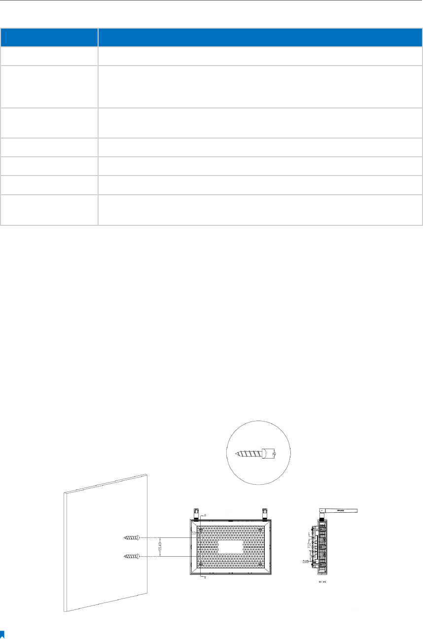
1. 4. Position Your AP Device
• Place your AP device in a well-ventilated place far from any heater or heating vent
• Avoid direct irradiation of any strong light (such as sunlight)
• Keep at least 2 inches (5 cm) of clear space around your AP device
• Operating Temperature: 0℃~40℃ (32℉~104℉)
• Operating Humidity: 10%~90%RH, Non-condensing
Generally, your AP device is placed on a horizontal surface. It also can be mounted on
the wall as shown below.
Note:
The diameter of the screw, 4mm<D<7mm, and the distance of two screws is 55.43mm. The screw that projects from
the wall needs around 3.5mm based, and the length of the screw need to be at least 20mm to withstand the weight
of the product.

Chapter 2
Operation Modes
The AP device supports four modes to satisfy user’s diversified network requirements
including Access Point mode, Repeater/Bridge mode, Client mode and multi-SSID
mode. This chapter introduces typical usage scenarios of each mode. You can choose
the desired scenario according to your needs, and refer to this part for hardware
connection instruction.
• Determine the Mode
• Connect Your AP Device
8
Chapter 2
2. 1. Determine the Mode
Use the following scenarios to determine an appropriate operating mode for your
network needs.
Modes Scenarios
Access Point mode (Default
mode)
You want to be able to access the Internet wirelessly, but this place only has an
Ethernet port (wired network) available. you need to transform the existing wired
network to a wireless network.
Repeater/Bridge mode You are in a Wi-Fi dead-zone or a place with weak wireless signal. You want to have
a greater effective range of the wireless signal throughout your home or office.
Client mode
You have a wired device with an Ethernet port and no wireless capability, for
example, a Smart TV, Media Player, or game console. You want to connect it to the
Internet wirelessly.
Multi-SSID mode
You want to divide the exsting Wi-Fi network into serveral networks for different
people with different access level and authority, for example, the guests, the host,
the children and the parents.
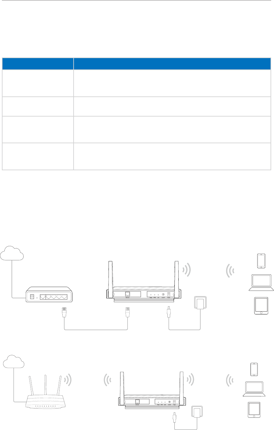
2. 2. Connect Your AP Device
Follow the figures below to connect your AP device.
• Access Point mode
Wired Router
Internet
AP300’s SSID
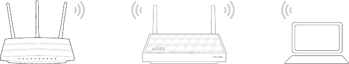
• Repeater/Bridge mode
Host AP
Internet
Host AP’s SSID AP300’s SSID
9
Chapter 2
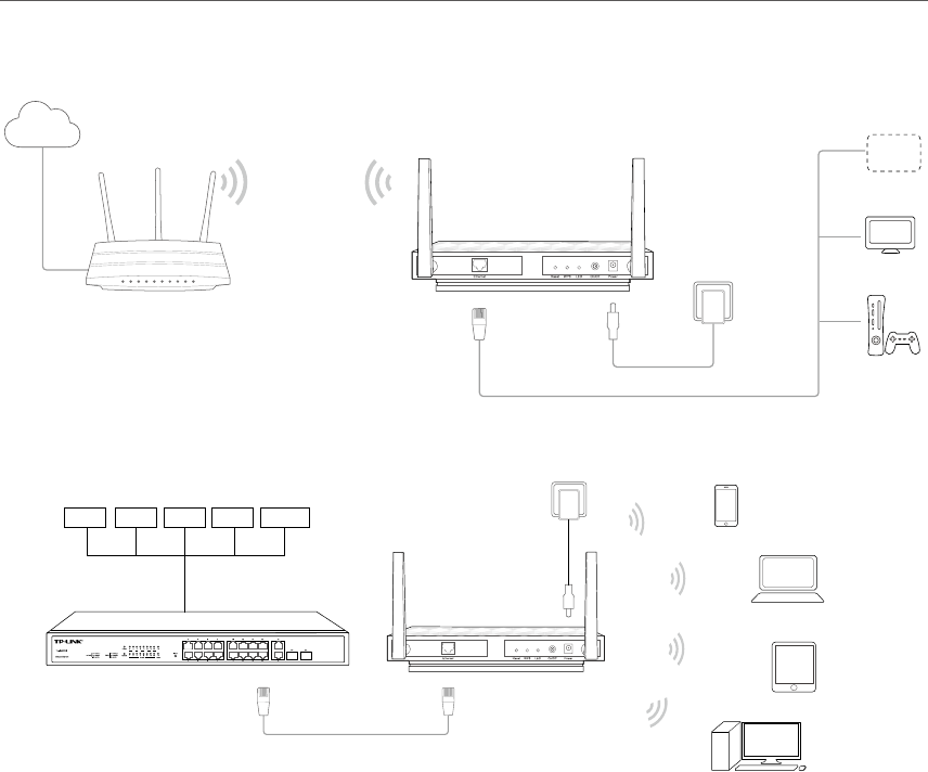
• Client mode
Host AP AP300
or
or
Other
Device
Internet
Host AP’s SSID
TV
• Multi-SSID mode
Switch
VLAN1 VLAN2 VLAN3 VLAN4
Router
Group A
AP300
SSID1
VLAN1
SSID2
VLAN2
SSID3
VLAN3
SSID4
VLAN4
Group B
Group C
Group D

Chapter 3
Log into Your AP Device
11
Chapter 3
With the Web-based management page, it is easy to configure and manage the AP
device. The Web-based utility can be used on any Windows, Macintosh or UNIX OS with
a Web browser, such as Microsoft Internet Explorer, Mozilla Firefox or Apple Safari.
Follow the steps below to log into your AP device.
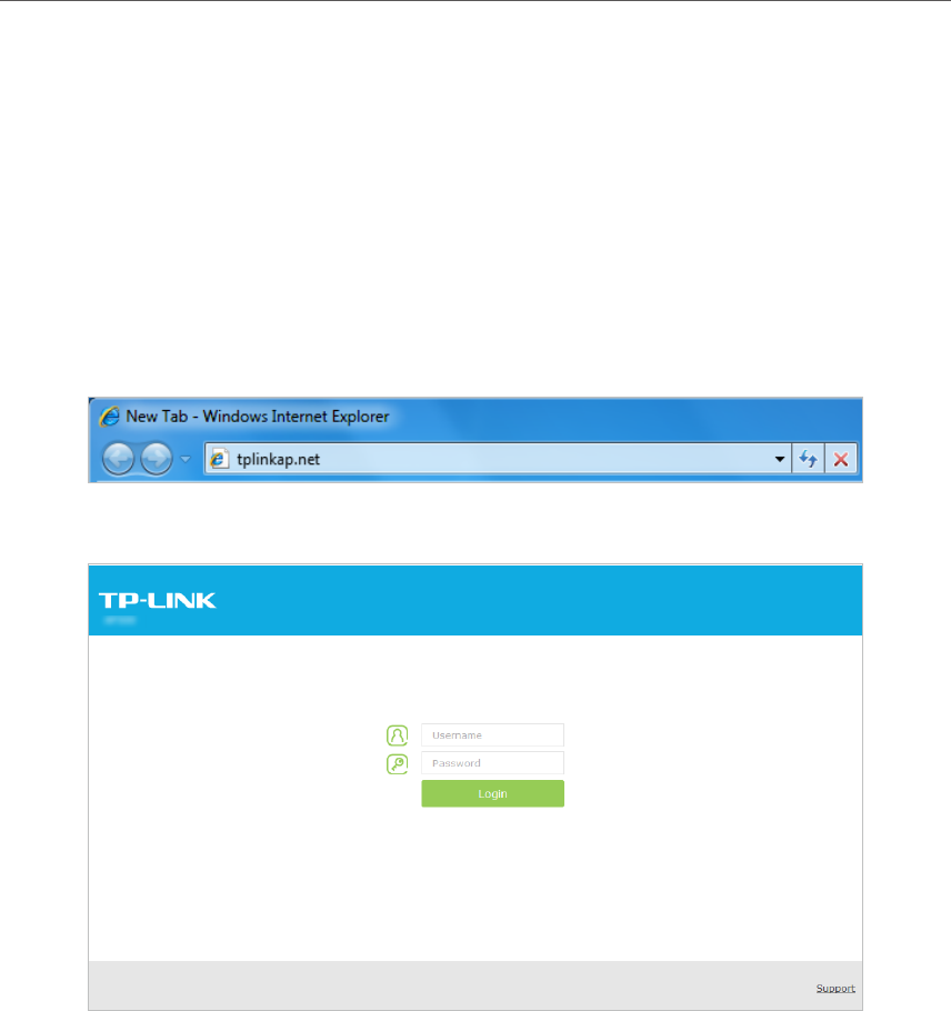
1. Set up the TCP/IP Protocol in Obtain an IP address automatically mode on your
computer.
2. Launch your Web browser. Enter http://tplinkap.net in the address field and Press
Enter (PC) or Return (Mac).
3. Upon initial login, please enter admin in the username and password fields.
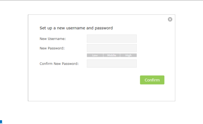
4. In the following pop-up window, it is recommended to change the device’s username
and password from its default settings for network security. Enter and confirm new
username and password, then click Confirm.

Chapter 4
Set Up Wireless
Connections
This chapter introduces how to connect your AP device to the wireless network. The
AP device is equipped with a web-based Quick Setup wizard. You can also set up the
wireless connection by the WPS feature or manually add a wireless connection.
This chapter contains the following sections:
• Quick Setup
• WPS
• Manually set up a wireless connection
• Check the connection status
14
Chapter 4
4. 1. Quick Setup
Quick Setup wizard allows you to quickly configure your AP device step by step. Choose
the suitable operation mode according to your network environment and follow the
step-by-step instructions.
1. Visit http://tplinkap.net, and log in with the username and password you set for the
AP device.
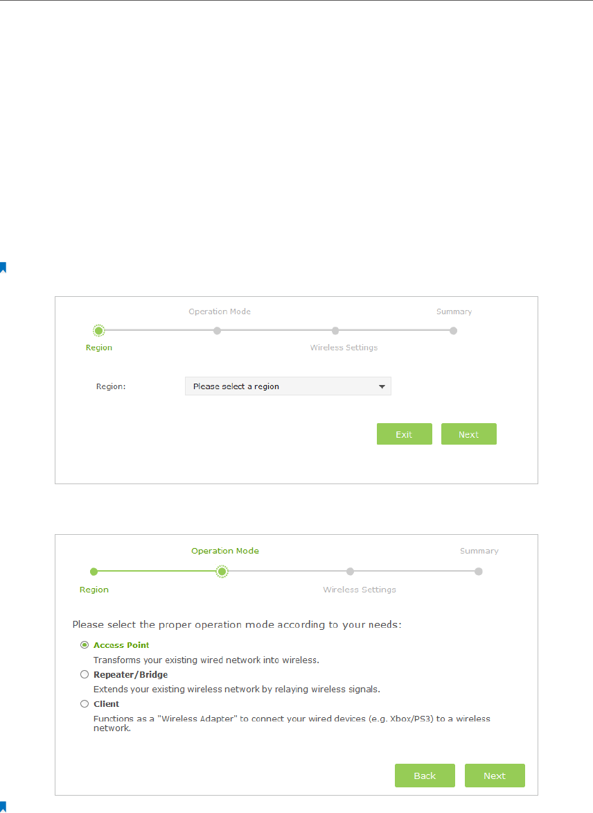
2. Go to Quick Setup on the top of the page.
3. Select your Region from the drop-down list and click Next.
Note: Per FCC regulations, all Wi-Fi products marketed in the U.S. are fixed to the U.S. region.
4. Please select the proper operation mode according to your needs and click Next.
Note:
You can configure the Access Point mode, Repeater/Bridge mode and Client mode using quick setup wizard. If you
want to use the multi-SSID mode, please go to Advanced > Wireless > Basic settings > Global Settings and choose
Multi-SSID from the drop-down list of the Operation Mode.
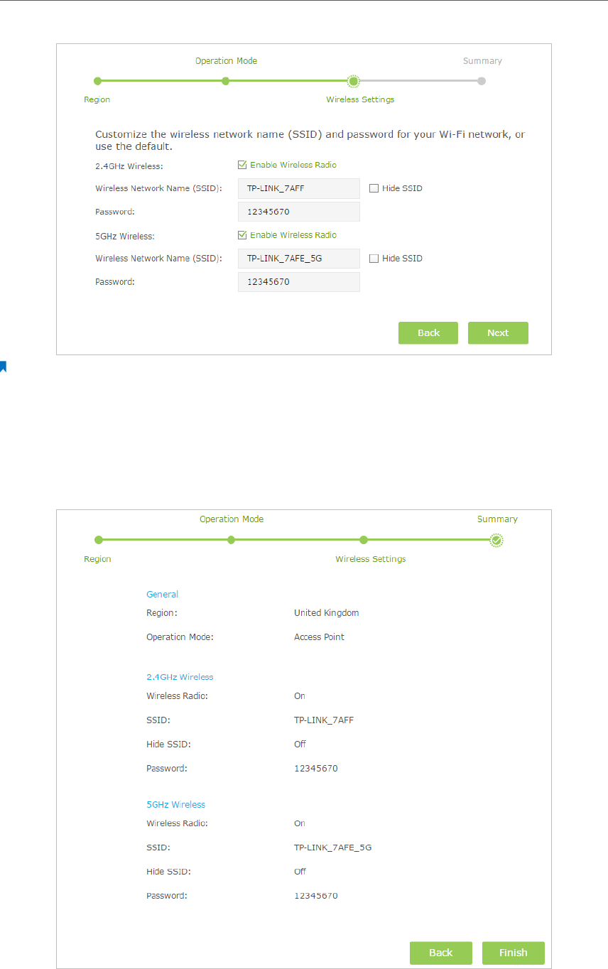
5. Follow the instructions on the page to configure the wireless settings. Click Next.
15
Chapter 4
Note:
1. The above wireless settings page in Access Point mode is used for demonstration. Page in Repeater/Bridge mode
or Client mode is different.
2. Tick Hide SSID if you want to hide the wireless network name.
3. Clicking Same as Host AP button will make the SSID of your extended wireless network the same as the Host AP
in Repeater/Brige mode.
6. Confirm the information and click Finish.
16
Chapter 4
4. 2. WPS
WPS (Wi-Fi Protected Setup) feature can help you to quickly and securely connect to
a network. WPS functions differently in different operation modes. In Access Point and
Multi-SSID modes, the WPS feature can be used only when the network security is set
to None or WPA2-PSK/AES. In Repeater/Bridge and Client modes, this device can use
WPS (Push button method) to connect to Host network while local wireless networks
do not support the WPS feature.
This section will guide you to add a new wireless device to an existing network quickly
by the WPS feature. There are two ways to use this feature: by push button method and
by PIN (Personal Identification Number). The PIN method can only be applied in Access
Point and Multi-SSID modes.
Push Button Method
Follow the steps below to use WPS by push button method.
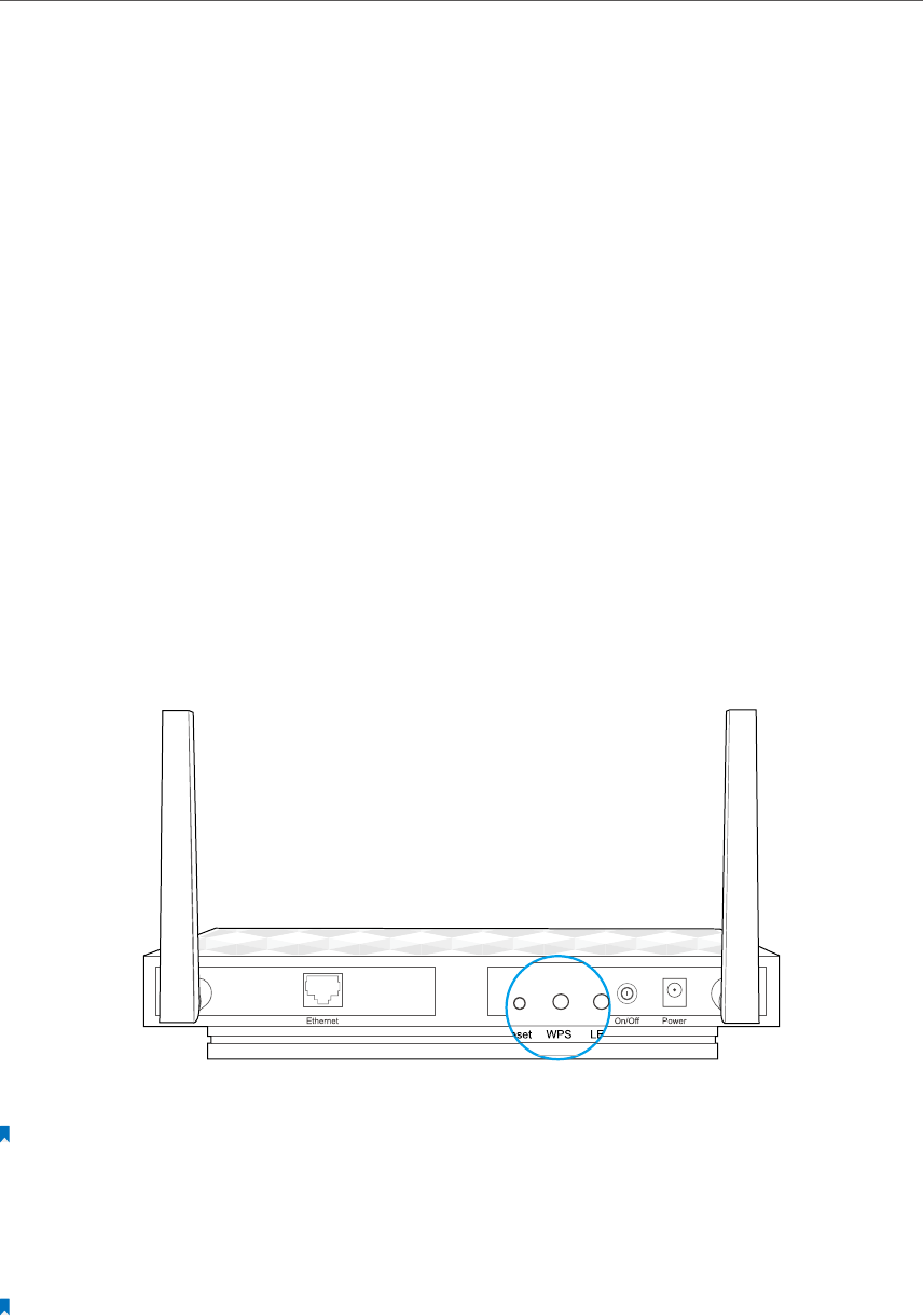
1. Press the WPS button on the real panel of the AP device. The WPS LED will blink slowly,
which shows the function has been triggered and the device is trying to connect or
to be conected. This process may take up to 2 minutes.
2. Press the WPS button of the device you want to connect to in 2 minutes.
Note:
The order to press the WPS button of the AP device and the device to be connected can be in reverse.
3. If the AP device’s WPS LED is solid on, it shows the WPS connection is successful. If
the AP device’s WPS LED blinks quickly, it shows the WPS connection is failed. Please
perform the steps again.
Note:
1. If the WPS connection is successful, after about 5 minutes, the WPS LED will turn off.
2. If the connection still fails, contact the technical support.
17
Chapter 4
PIN Method
Other devices can connect to this AP device by WPS with the AP device’s PIN and the AP
device can connect to other devices by entering their PINs. The PIN method can only be
applied in Access Point and Multi-SSID modes.
Follow the steps below to use WPS by PIN method.
1. Visit http://tplinkap.net, then log in with the username and password you set for the
AP device.
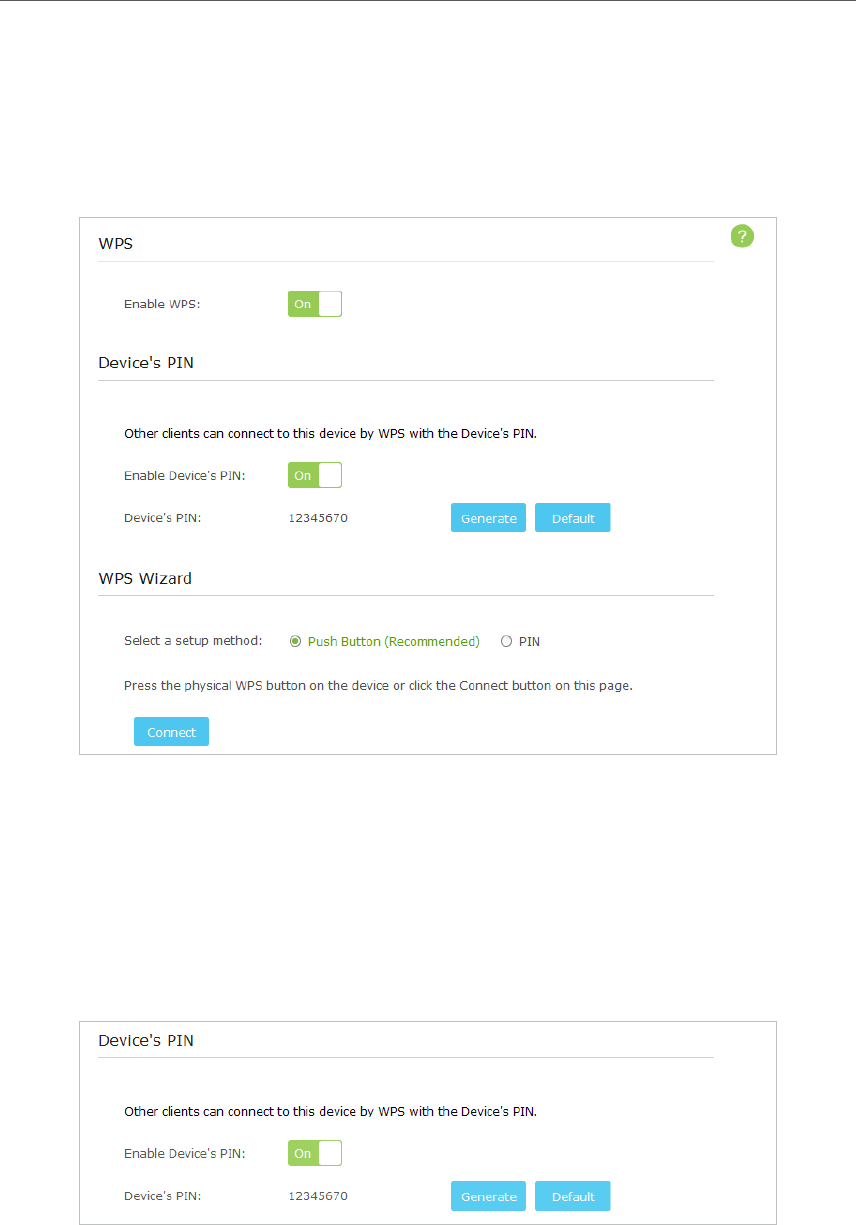
2. Go to Advanced > Wireless > WPS. There are also two ways to use WPS PIN method:
using the AP device’s PIN and using the wireless client’s PIN.
¾Using the AP Device‘s PIN
1 ) Toggle On Enable Device’s PIN to allow wireless clients to connect to the device
using the Device’s PIN.
18
Chapter 4
2 ) Click Generate to generate a new PIN randomly or click Default to restore the
current PIN to the factory default PIN. Using this PIN to connect to the AP
device. The default PIN can be found on the label of the AP device.
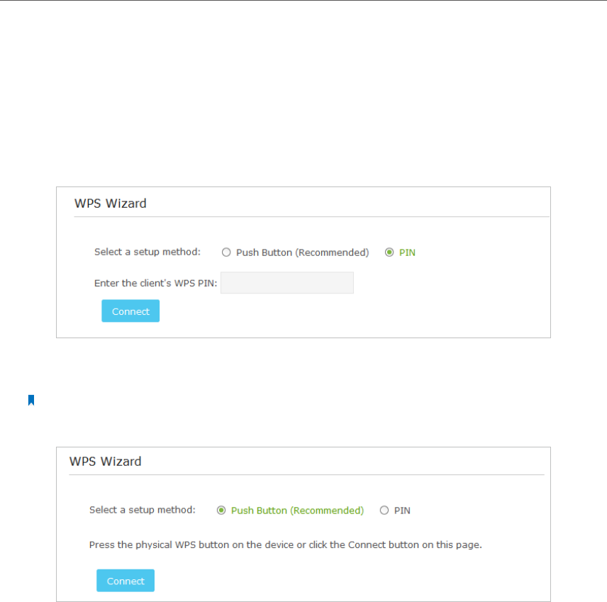
¾Using the wireless client’s PIN
1 ) Select the PIN as the setup method.
2 ) Entering the wireless client’s WPS PIN into Enter the client’s WPS PIN field and
click Connect.
Note:
Selecting Push button method (Recommended) is equal to pressing the physical WPS button on the device.
4. 3. Manually set up a wireless connection
Follow the steps below to check or modify your wireless connection settings.
1. Visit http://tplinkap.net, then log in with the username and password you set for the
AP device.
2. Go to Advanced > Wireless > Basic Settings.
19
Chapter 4
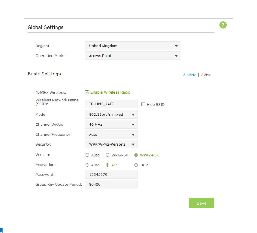
3. Select the Region and Operation mode from the drop-down list.
Note: Per FCC regulations, all Wi-Fi products marketed in the U.S. are fixed to the U.S. region.
¾Access Point Mode
If Access Point mode is selected, please take the following steps:
20
Chapter 4
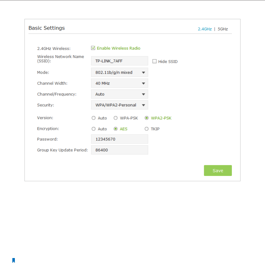
1 ) Select the wireless network 2.4GHz or 5GHz. Here we take 2.4GHz for
demostration.
2 ) The wireless radio is enabled by default. Customize the Wireless Network Name
(SSID) and Security settings. The AP device provides four security options, None,
WPA/WPA2 - Personal, WPA/WPA2 - Enterprise and WEP. The default WPA/WPA2
- Personal is recommended. Enter a Password below to prevent unauthorized
access to your AP device.
Note:
1. It is recommended to keep the default settings for other parameters. If it is necessary to change the related
parameters, please refer to the help page.
2. Tick Hide SSID if you want to hide this wireless network name.
3 ) Click Save to save all your settings.
In addition
• Mode - Select the transmission mode for your wireless client devices, 802.11b/g/n
mixed, 802.11g/n mixed or 802.11n only for 2.4GHz and 802.11a/n/ac mixed,
802.11n/ac mixed or 802.11ac only for 5GHz. It is recommended to keep the
default settings.
• Channel Width - Select a channel width for the wireless network, 40MHz or 20MHz
for 2.4GHz and 80MHz, 40MHz or 20MHz for 5GHz.
• Channel/Frequency - Select an operating channel for the wireless network. The
default channel is Auto, which finds the best channel available automatically. It
is recommended to leave the channel to Auto if you are not experiencing the
intermittent wireless connection issue.
21
Chapter 4
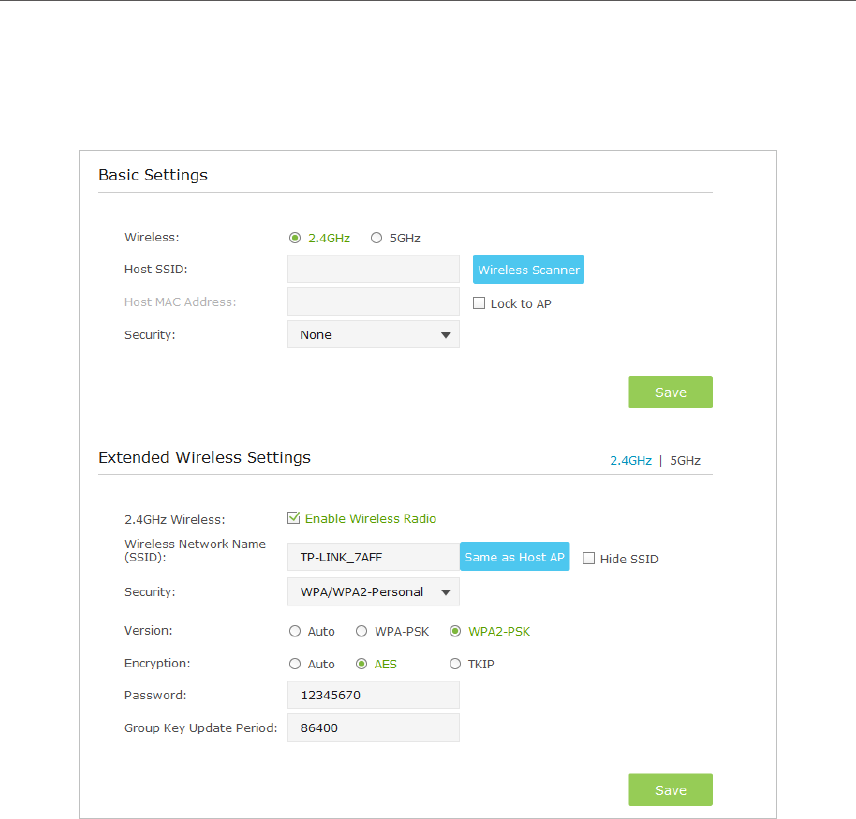
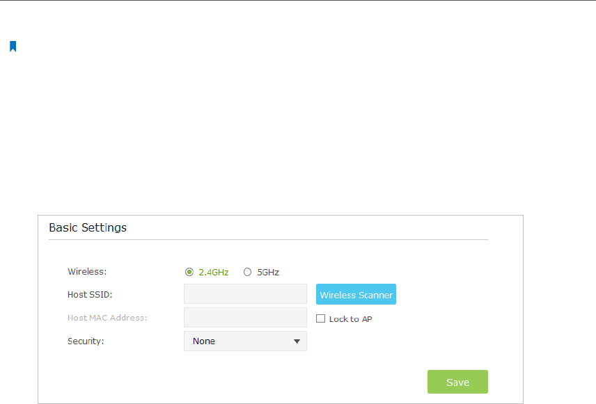
¾Repeater/Bridge Mode
If Repeater/Bridge mode is selected, please take the following steps:
1 ) Select the wireless network 2.4GHz or 5GHz to connect. Here we take 2.4GHz
for demostration.
2 ) Enter the exact same wireless settings of the Host network that you want to
connect to. Or click Wireless Scanner and choose a Host network from the list.
Once a network is selected, its SSID, MAC address and security settings (except
the password) will be automatically filled in the respective fields. If the selected
network is protected, enter the password.
3 ) Click Save to save the settings.
4 ) Select the wireless network 2.4GHz or 5GHz to configure the extended wireless
settings. Here we take 2.4GHz for demostration.
5 ) The wireless radio is enabled by default. Customize the Wireless Network Name
(SSID) and Security settings. The AP device provides four security options, None,
WPA/WPA2 - Personal, WPA/WPA2 - Enterprise and WEP. The default WPA/WPA2
- Personal is recommended. Enter a Password below to prevent unauthorized
access to your AP device.
22
Chapter 4
Note:
1. If you want to automatically copy the same SSID and security settings as the Host AP, click the Same as Host
AP button .
2. If you want to hide this wireless network name, tick Hide SSID.
6 ) Click Save to save the settings.
¾Client Mode
If Client mode is selected, please take the following steps:
1 ) Select the wireless network 2.4GHz or 5GHz to connect. Here we take 2.4GHz
for demostration.
2 ) Enter the exact same wireless settings of the Host network that you want to
connect to. Or click Wireless Scanner and choose a Host network from the list.
Once a network is selected, its SSID, MAC address and security settings (except
the password) will be automatically filled in the respective fields. If the selected
network is protected, enter the password.
3 ) Click Save to save the settings.
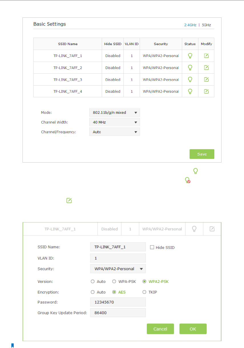
¾Multi-SSID Mode
If Multi-SSID mode is selected, please take the following steps:
23
Chapter 4
1 ) The list will show the information of the Multi-SSID. The icon means this SSID
is enabled, and you can click it to disable. While the icon means this SSID is
disabled, and you can click it to enable.
2 ) Click the icon to modify the SSID, VLAN ID, wireless security and other
settings of the corresponding network.
Note:
Tick Hide SSID if you want to hide this wireless network name.
3 ) Click OK to save the settings.
24
Chapter 4
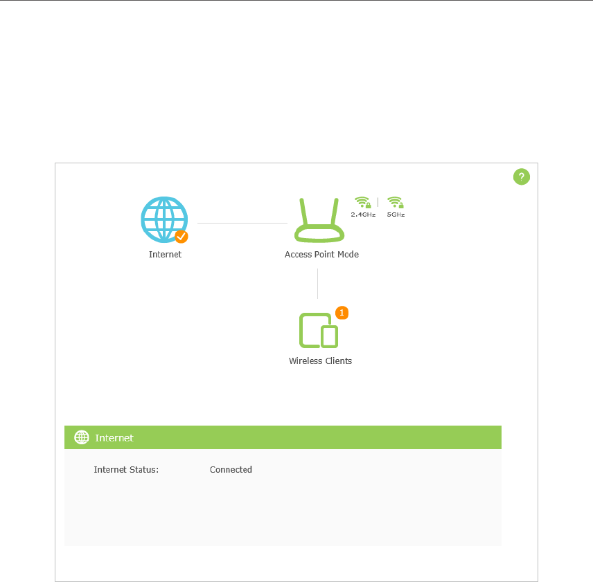
4. 4. Check the connection status
After finishing the configuration, please go to Advanced > Status to check the connection
status. Here we take Access Point mode as a demonstration. The status page of other
modes are different. Click each element of the topology, its status will show below.

Chapter 5
Customize Your Network
and Security Settings
This chapter guides you on how to configure advanced network and security settings
that are available for this AP device.
This chapter contains the following sections:
• Change the LAN Settings
• Specify DHCP Server Settings
• MAC Filtering
• Advanced Wireless Settings
26
Chapter 5
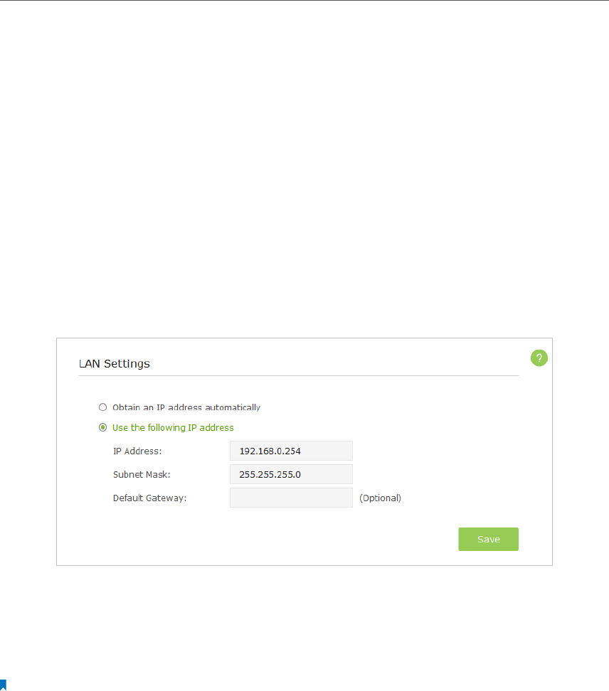
5. 1. Change the LAN Settings
The AP device is preset to Obtain an IP address automatically, which allows the device
to dynamically obtain an IP address and gateway from the main router/AP. You just need
to enter http://tplinkap.net into the address bar to log into the web-based management
page. It is recommended to keep the default LAN settings to avoid IP conflict with the
main router/AP or other device on your local network. If it is necessary to change the
LAN settings, for example, your network requires a specific IP subnet, please perform
the following steps.
1. Visit http://tplinkap.net, and log in with the username and password you set for the
AP device.
2. Go to Advanced > Network > LAN page.
3. Select Use the following IP address option and type in a new IP Address appropriate
to your needs.
4. Leave the Subnet Mask and Default Gateway as it is.
5. Click Save.
Note:
After changing the IP address, you should enter the new IP address or use the domain name tplinkap.net to log into
the web-based management page.
5. 2. Specify DHCP Server Settings
By default, the DHCP (Dynamic Host Configuration Protocol) Server is set to Auto. If the
DHCP server of the host router/AP is disabled, the device’s DHCP server will automatically
assign valid IP addresses to clients. If the DHCP server of the host router/AP is enabled,
the device’s DHCP server will be unable to avoid IP conflict. You can switch On (enable)
or Off (disable) the DHCP server. If Off is selected and there is no other DHCP server
within your LAN, you have to configure the IP address for each client manually.
27
Chapter 5
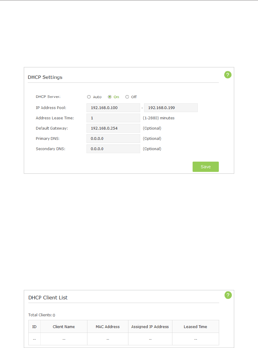
¾DHCP Settings
1. Visit http://tplinkap.net, and log in with the username and password you set for the
AP device.
2. Go to Advanced > Network > DHCP Server.
3. Switch On the DHCP server.
4. Enter the starting and ending IP address in the IP Address Pool.
5. Enter other parameters if the ISP offers, the Default Gateway is automatically filled
which is the same as the LAN IP address of the AP device.
6. Click Save.
¾Check the DHCP Clients
1. Visit http://tplinkap.net, and log in with the username and password you set for the
AP device.
2. Go to Advanced > Network > DHCP Client List to check the DHCP Client List.
¾To reserve an IP address for a specified client device:
1. Visit http://tplinkap.net, and log in with the username and password you set for the
AP device.
2. Go to Advanced > Network > IP Address Reservation.
3. Click Add.
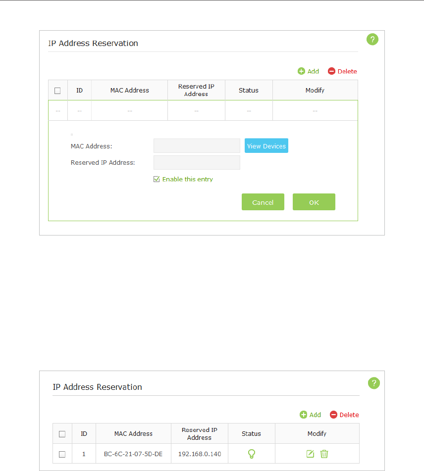
28
Chapter 5
4. Click View Devices or enter the MAC address of the client device.
5. Enter the IP address to set to the client device.
6. Select the Enable this entry checkbox.
7. Click OK.
The IP address reservation is configured successfully, and you can see the rule shown
as below.
5. 3. MAC Filtering
MAC Filtering is used to allow or block specific client devices from accessing your
network. When a device is blocked, it is unable to connect to the Internet through your
network or communicate with other devices in the LAN.
To use MAC Filtering, enable this function and specify a blacklist or whitelist. If MAC
Filtering is disabled (Off), all devices, including the blacklisted ones, are allowed to
access your network.
1. Visit http://tplinkap.net, and log in with the username and password you set for the
AP device.
2. Go to Advanced > Network > MAC Filtering and toggle on the MAC filtering function.
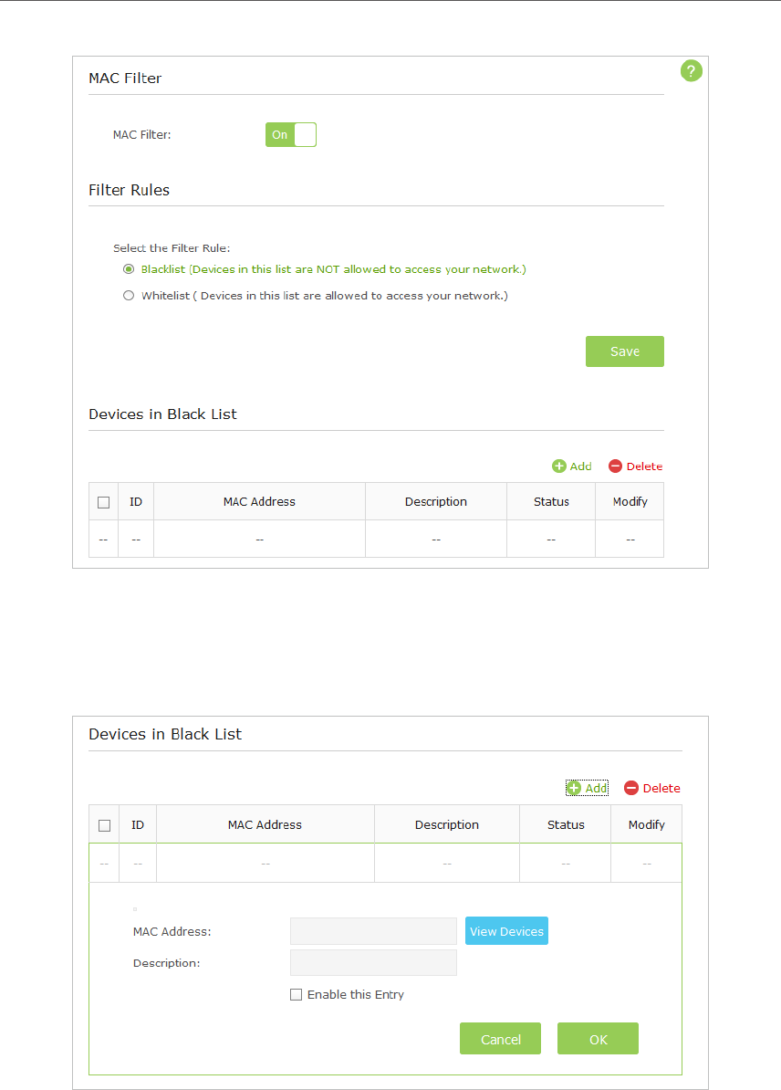
29
Chapter 5
3. Select the filtering rule: Blacklist or Whitelist.
¾To add a device to a blacklist or whitelist
1 ) Click Add.
2 ) Enter the MAC address of the device or click View Devices button to choose the
device that you want to add in the blacklist or whitelist from the Access Devices
List.
3 ) Enter a brief description of the device.
30
Chapter 5
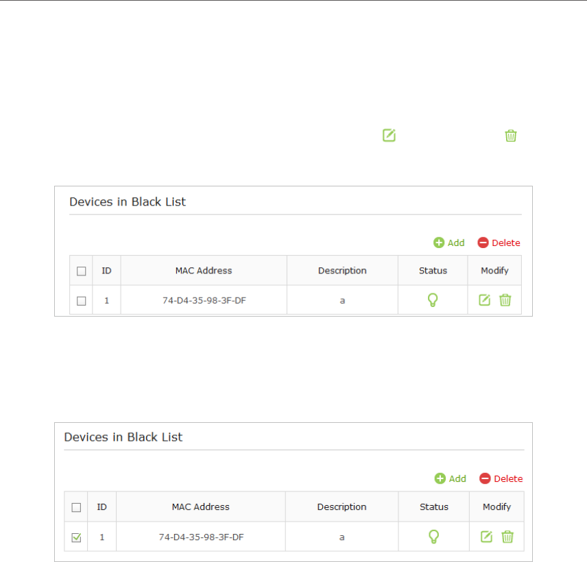
4 ) Select the Enable this Entry checkbox.
5 ) Click OK.
¾To modify or delete a device from the Blacklist or Whitelist
In the Blacklist or Whitelist, click the modify icon or the delete icon that
corresponds to the device that you wish to modify or delete.
¾To delete multiple devices from the Blacklist or Whitelist
In the Blacklist or Whitelist, select the corresponding checkboxes of the devices to
be deleted and click Delete above the table.
5. 4. Advanced Wireless Settings
It is recommended to keep the default settings of the advanced wireless settings. If it is
necessary to change them, please perform the following steps.
1. Visit http://tplinkwifi.net, and log in with the username and password you set for the
AP device.
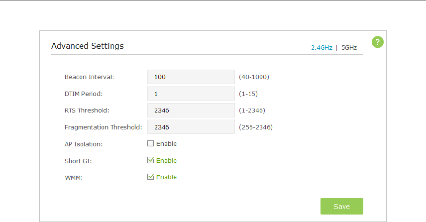
2. Go to Advanced > Wireless > Advanced Settings.
31
Chapter 5
3. Choose the 2.4Ghz or 5GHz of the wireless network.
• Beacon Interval - Enter a time interval between 40 and 1000 in milliseconds
to determine the duration between beacon packets that are transmitted
periodically by the device to synchronize the wireless network. The default is
100 milliseconds.
• DTIM - This value determines the interval of the Delivery Traffic Indication
Message (DTIM). You can specify the value between 1 and 15 Beacon Intervals.
The default value is 1, which indicates the DTIM Period is the same as Beacon
Interval.
• RTS Threshold - Enter a value between 1 and 2346 to determine the packet
size of data transmitted through the network. By default, the RTS (Request
to Send) Threshold size is 2346. If the packet size is greater than the preset
threshold, the device sends Request to Send frames to a particular receiving
station and negotiates the sending of a data frame, or else the packet will be
sent immediately.
• Fragmentation Threshold - Specify the maximum packet size (in bytes)
transmitted through the network. If a packet size exceeds the fragmentation
threshold, the packet will be fragmented into multiple packets. Note that setting
the fragmentation threshold too low may result in poor network performance
because of excessive packets. The default and recommended setting is 2346
bytes.
• AP Isolation - Select this checkbox to enable the AP Isolation feature that
allows you to confine and restrict all wireless devices on your network from
interacting with each other, but still able to access the Internet. AP isolation is
disabled by default.
• Short GI - This function is enabled by default and recommended to increase the
data capacity by reducing the Guard Interval (GI) time.

32
Chapter 5
• WMM - This function guarantees the packets with high-priority messages being
transmitted preferentially. It is enabled by default and highly recommended.
4. Click Save.

Chapter 6
Manage Your AP Device
This chapter will show you how to configure and manage your AP device. This chapter
includes the following sections:
• System Log
• Test the Network Connectivity
• Upgrade the Firmware
• Backup and Restore Configuration Settings
• Change the Management Account
• Throughput Monitor
• Statistics
• SNMP Management
• Ping Watchdog
• LEDs Control
34
Chapter 6
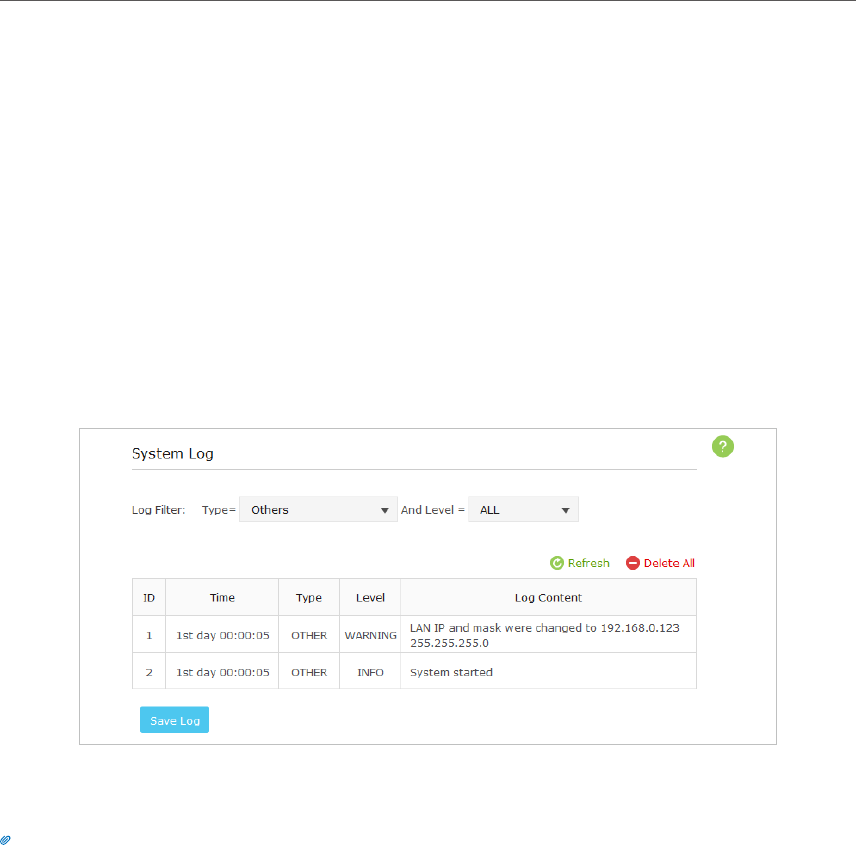
6. 1. System Log
The System Log page displays a list of the most recent activities (events) of the network.
You can define the type of logs and/or the level of logs you want to view. You can also
export the log files to a computer. When the AP device does not work properly, you can
save the system log and send it to the technical support for troubleshooting.
¾To Save the System Log in Local:
1. Visit http://tplinkap.net, and log in with the username and password you set for the
AP device.
2. Go to Advanced > System Tools > System Log.
3. Choose the type and level of the system log according to your need.
4. Click Save Log to save the system log to local.
Tips:
You can use the email to send the saved system log to the technical support for troubleshooting.
Click Refresh to renew the system log list or click Delete all to delete all the system logs.
6. 2. Test the Network Connectivity
Diagnostics is used to test the connectivity between the AP device and the host or
other network devices.
The device provides Ping and Traceroute tools to help you troubleshoot network
connectivity problems. The Ping tool sends packets to a target IP address and logs
the results, such as the number of packets sent/received, and the round-trip time. The
Traceroute tool sends packets to a target IP address and displays the number of hops
and time to reach the destination. You can ping and traceroute a local device by its IP
address.
35
Chapter 6
1. Visit http://tplinkwifi.net, and log in with the username and password you set for the
AP device.
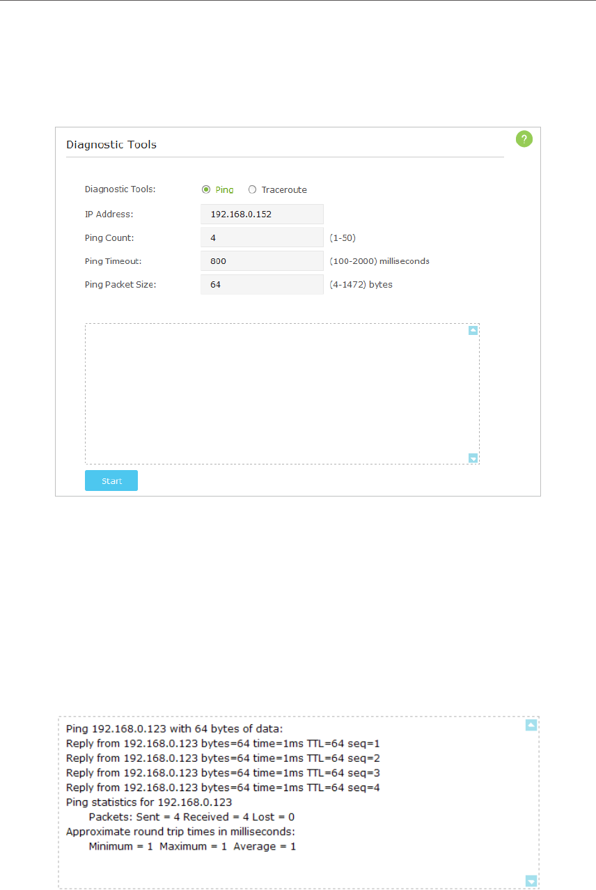
2. Go to Advanced > System Tools > Diagnostics.
¾To diagnose using Ping
1 ) Choose Ping as the diagnostic tool to test the connectivity.
2 ) Enter the target IP Address of the tested host.
3 ) Specify the Ping Count, Ping Timeout and Ping Packet Size. (Optional)
4 ) Click Start.
The figure below indicates the proper connection between the device and the IP
address 192.168.0.123 tested through Ping.
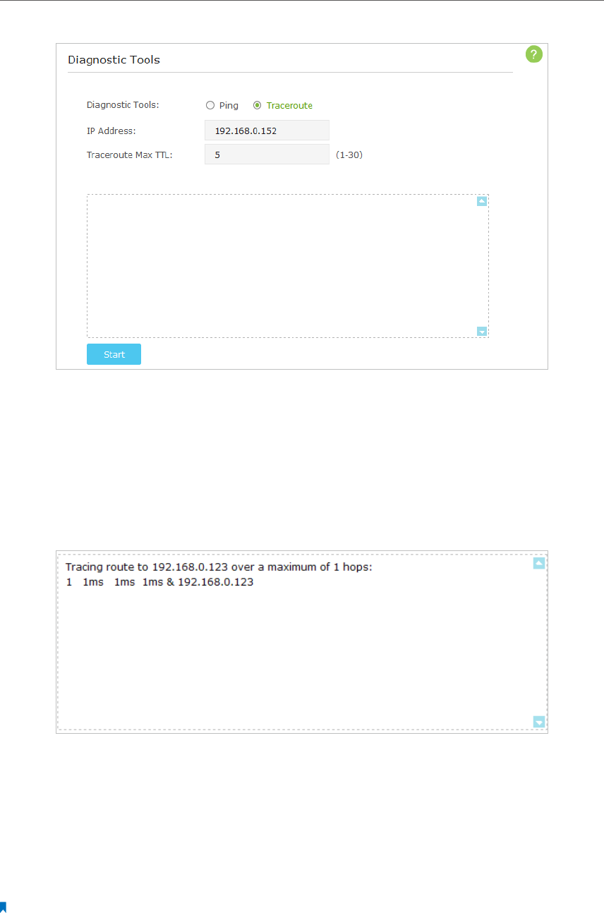
¾To diagnose using Traceroute
1 ) Choose Traceroute as the diagnostic tool to test the connectivity.
36
Chapter 6
2 ) Enter the target IP Address of the tested host.
3 ) Specify the number of hops (to be reached) in the Traceroute Max TTL (Time to
Live) field. The default is 20. (Optional)
4 ) Click Start.
The figure below indicates the proper connection between the AP device and the
IP address 192.168.0.123 tested through Traceroute.
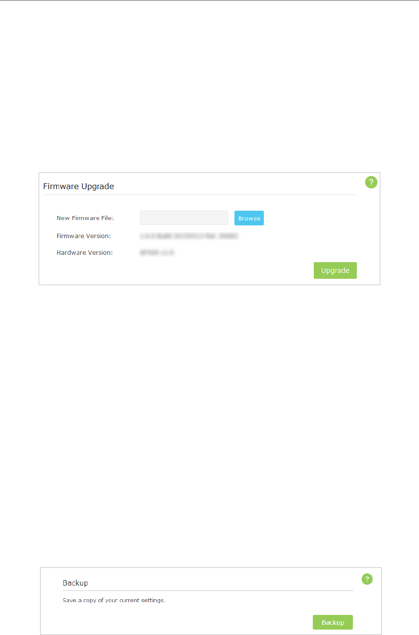
6. 3. Upgrade the Firmware
TP-LINK is dedicated to improving and richening the product features, giving you a
better network experience. We will release the latest firmware at TP-LINK official website,
you can download the latest firmware file from the Support page of our website www.
tp-link.com and upgrade the firmware to the latest version.
Note:
1. Make sure the latest firmware file matches with the hardware version (as shown in the webpage).
2. Make sure that you have a stable connection between the AP device and your computer. It is NOT recommended
to upgrade the firmware wirelessly.
37
Chapter 6
3. Back up your AP device configuration.
4. Do NOT turn off the AP device during the firmware upgrade.
Follow the steps to upgrade the firmware.
1. Download the latest firmware file for the AP device from our website www.tp-link.
com.
2. Visit http://tplinkap.net, and log in with the username and password you set for the
AP device.
3. Go to Advanced > System Tools > Firmware Upgrade.
4. Click Browse to locate the downloaded new firmware file, and click Upgrade.
5. Wait a few moments for the upgrading and rebooting.
6. 4. Backup and Restore Configuration Settings
The configuration settings are stored as a configuration file in the AP device. You can
backup the configuration file to your computer for future use and restore the AP device
to a previous settings from the backup file when needed. Moreover, if necessary you
can erase the current settings and reset the AP device to the default factory settings.
1. Visit http://tplinkap.net, and log in with the username and password you set for the
AP device.
2. Go to Advanced > System Tools > Backup & Restore.
¾To backup configuration settings:
It is highly recommended to back up your current configurations in case a recovery is
needed to restore the system to a previous state or from the factory defaults.
38
Chapter 6
Click Backup to save a copy of the current settings to your local computer. A ‘.bin’ file of
the current settings will be stored to your computer. Make sure to save the backup file
to a safe location that you can retrieve and restore the device later, if needed.
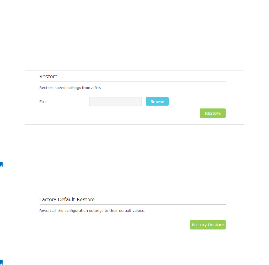
¾To restore configuration settings:
1 ) Click Browse to locate the backup configuration file stored on your computer,
and click Restore.
2 ) Wait a few moments for the restoring and rebooting.
Note: During the restoring process, do not turn off or reset the AP device.
¾To reset the AP device to factory default settings:
1 ) Click Factory Restore to reset the router.
2 ) Wait a few moments for the reset and reboot.
Note:
1. During the resetting process, do not turn off the AP device.
2. We strongly recommend you back up the current configuration settings before resetting the AP device.
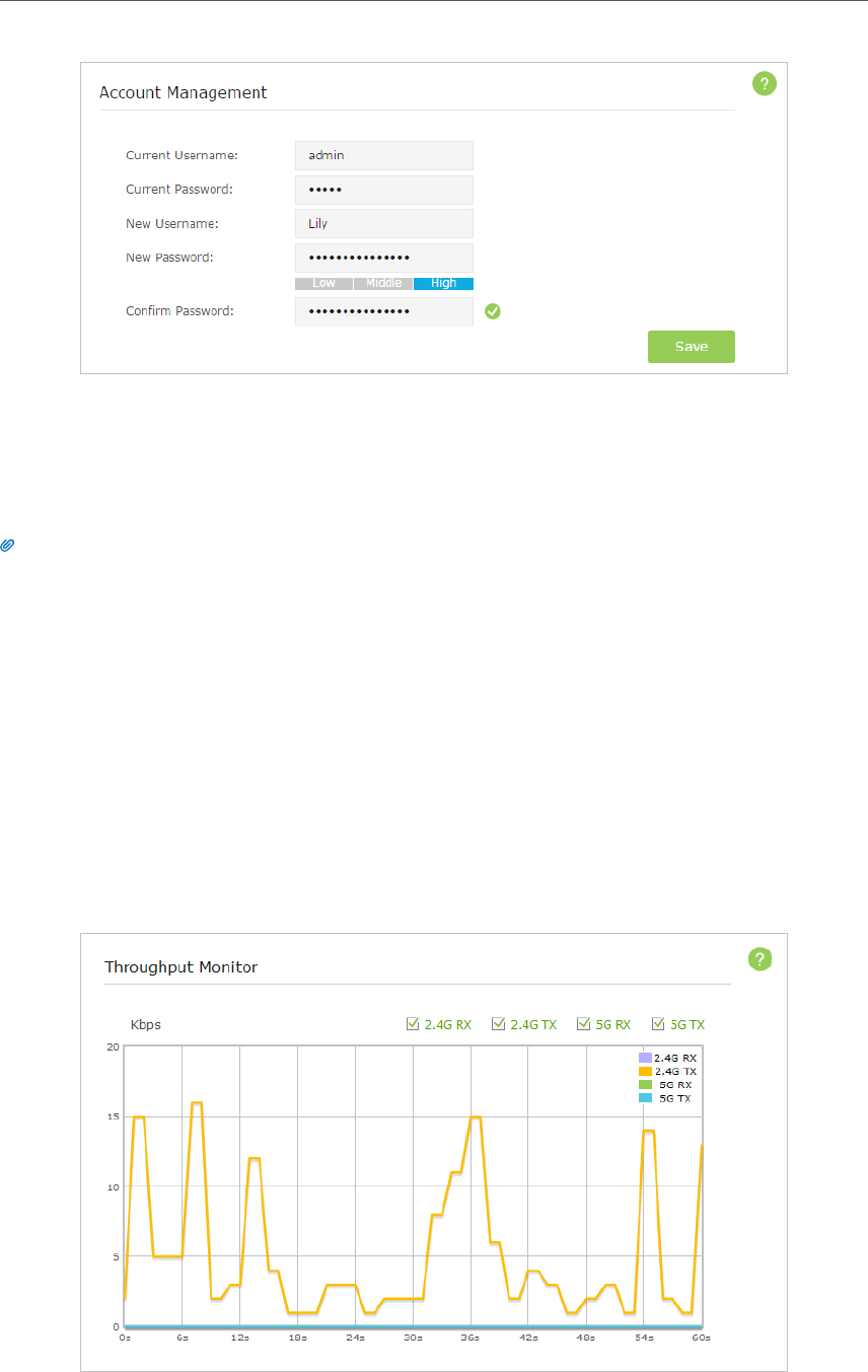
6. 5. Change the Management Account
The account management feature allows you to change your login username and
password of the web-based management page.
1. Visit http://tplinkap.net, and log in with the username and password you set for the
AP device before.
2. Go to Advanced > System Tools > Account Management and complete the settings in
Account Management section.
39
Chapter 6
3. Enter the current username and password.
4. Enter the new username and the new password twice (both case-sensitive). Click
Save.
Use the new username and password for subsequent logins.
Tips: Please write down the new login information in a secure place in case you forget it.
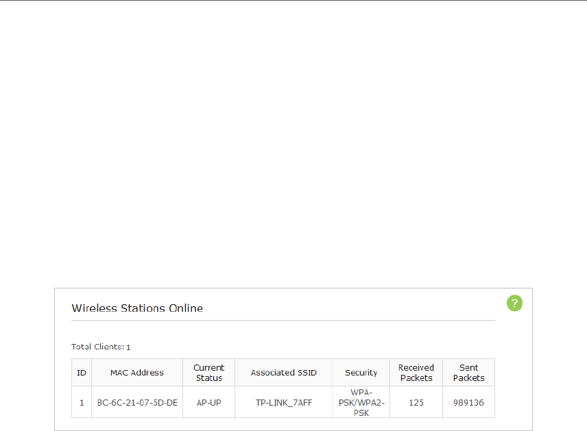
6. 6. Throughput Monitor
The throughput chart displays the current data traffic of the network. The curves in
different colors represent the received (RX) and transmitted (TX) rates of the 2.4GHz
and 5GHz frequencies respectively. You can choose to view individual or multiple data
rates by selecting the corresponding checkbox.
1. Visit http://tplinkap.net, and log in with the username and password you set for the
AP device.
2. Go to Advanced > Wireless > Throughput Monitor.
40
Chapter 6
3. Select the corresponding checkbox (2.4G RX, 2.4G TX, 5G RX and 5G TX) to view
individual or multiple data rates.
6. 7. Statistics
The Statistics page displays the network traffic of wireless stations sent and received,
and allows you to monitor the volume of wireless traffic statistics.
1. Visit http://tplinkap.net, and log in with the username and password you set for the
AP device.
2. Go to Advanced > Wireless > Statistics.
3. Monitor the traffic statistics in Wireless Stations Online section.
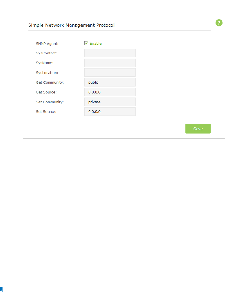
6. 8. SNMP Management
SNMP (Simple Network Management Protocol) is a popular network monitoring and
management protocol.
1. Visit http://tplinkap.net, and log in with the username and password you set for the
AP device.
2. Go to Advanced > System Tools > SNMP and complete the settings according to your
needs.
41
Chapter 6
3. Select the SNMP Agent checkbox to enable (or deselect to disable) the SNMP feature.
4. Enter the contact email address in SysContact field, a user-defined name in SysName
field and the physical location in SysLocation of the node to be managed.
5. Enter the community name in Get Community field that allows read-only access
to the device’s SNMP information. The community name is considered as a group
password. The default setting is public.
6. Enter the IP address or subnet in Get Source field that management systems can read
information from this ‘get’ community.
7. Enter the community name in Set Community field that allows read/write access to
the device’s SNMP information. The community name can be considered as a group
password. The default setting is private.
8. Enter the IP address or subnet in Set Source field that management systems can read
and write to this ‘set’ community.
9. Click Save.
Note:
A restricted source can be a specific IP address (e.g. 10.10.10.1), or a subnet - represented as IP/BITS (e.g. 10.10.10.0/24).
If 0.0.0.0 is specified as the IP address, the agent will accept all requests under the corresponding community name.
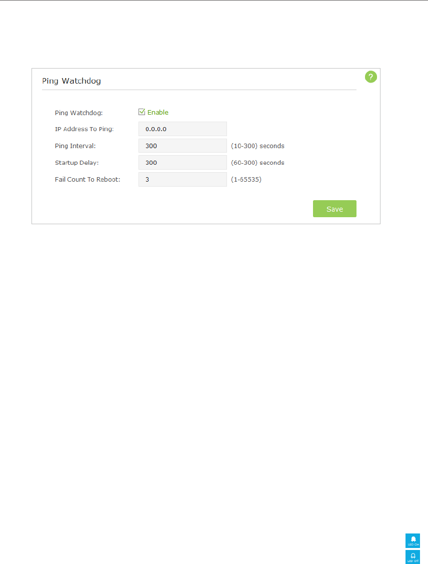
6. 9. Ping Watchdog
The Ping Watchdog feature allows you to continuously ping a specific remote host
for connection status using a user-defined IP address (or an Internet gateway). If it is
unable to ping the target IP address under the user-defined constraints, this device will
automatically reboot.
1. Visit http://tplinkap.net, and log in with the username and password you set for the
AP device.
42
Chapter 6
2. Go to Advanced > System Tools > Ping Watchdog and complete the settings according
to your needs.
3. Select the Ping Watchdog checkbox to enable the function.
4. Enter the IP address of the target host in IP Address To Ping field that you want to
send ping packets to.
5. Enter the time interval (in seconds) between two continuous ping packets in Ping
Interval field.
6. Enter the time delay (in seconds) before the first ping packet is sent out when the
device is restarted in Startup Delay field.
7. Enter a number of ping count(s) that the device can send continously in Fail Count To
Reboot field. If the value is exceeded, the device will restart automatically.
8. Click Save.
6. 10. LEDs Control
The LEDs indicate AP device’s activities and behavior. You can turn on or turn off the AP
device’s LEDs from the web-based management page.
1. Visit http://tplinkap.net, and log in with the username and password you set for the
AP device.
2. Click the LED On or LED Off icon on the top right corner of the page. The icon
displays that the LEDs is on and you can click it to turn off the LEDs. The icon
displays that the LEDs is off and you can click it to turn on the LEDs.

43
FAQ
Q1. What can I do if I forgot my wireless password?
The default password is labeled at the back of the AP device. If the password has been
altered, please connect the AP device to the computer using a cable and follow the
steps below:
1. Visit http://tplinkap.net, and log in with the username and password you set for the
AP device.
2. Go to Advanced > Wireless >Basic setings. Locate the password on the page and mark
it down for future use.
Q2. How to retrieve the username and password of the web management
page?
The default username and password of the web management page are admin (in lower
case). If the password has been altered, please follow the steps below:
1. Reset the router to factory default settings: with the device powered on, use a pin to
press and hold the Reset button for five seconds until the Power LED starts blinking,
then release the button;
2. Visit http://tplinkap.net;
3. Enter admin (in lower case) as both username and password to log in.
Note: You’ll need to reconfigure the AP device. Please mark down your new password for future use.
Q3. I cannot log into the AP device’s web management page, what can
I do?
This can happen for a variety of reasons, please try the methods below and try again.
1. Make sure the AP device connects to the computer correctly and the corresponding
LED indicator(s) light up.
2. Make sure the IP address of your computer is configured as Obtain an IP address
automatically and Obtain DNS server address automatically.
3. Make sure the http://tplinkap.net you input is right.
4. Check your computer’s settings:
1 ) Go to Start > Control Panel > Network and Internet, and click View network status
and tasks;
2 ) Click Internet Options on the bottom left;
3 ) Click Connections, select Never dial a connection;
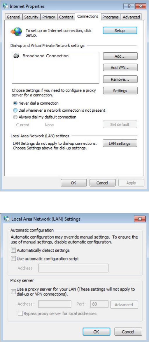
44
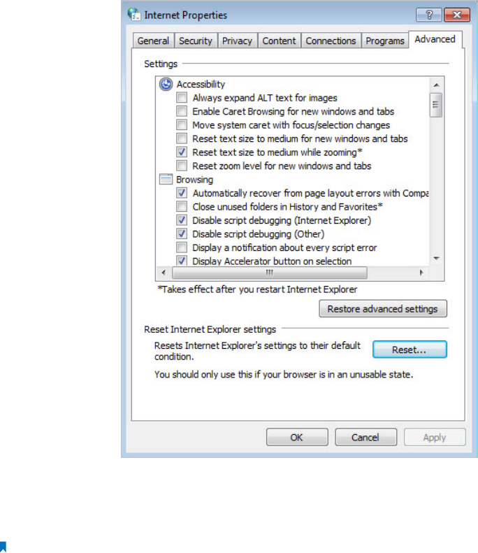
4 ) Click LAN settings, deselect the following three options and click OK;
5 ) Go to Advanced > Restore advanced settings, click OK to save the settings.
45
5. Change a web browser or computer and log in again.
6. Reset the AP device to factory default settings: use a pin to press and hold the Reset
button for five seconds until the Power LED starts blinking, then release the button.
Note: Upon resetting, all previous configurations will be cleared, and the AP device will reset to the default AP
Mode.
Open a web browser and log in again. If login still fails, please contact the technical
support.
Q4. What can I do if the login window does not appear?
You can try the following methods to solve the problem:
• Change the computer’s static IP address to obtain an IP address automatically.
• Verify if http://tplinkap.net or http://192.168.0.254 is correctly entered in the web
browser.
• Use another web browser and try again.
• Reboot your AP device and try again.
• Power off your host AP and enter http://tplinkap.net into the web browser to try
again.
46
Q5. What can I do if my wireless is not stable?
It may be caused by too much interference, you can try the following methods:
• Set your wireless channel to a different channel.
• Move the AP device to a new location away from Bluetooth devices and other
household electronics, such as cordless phone, microwave, and baby monitor, etc., to
minimize signal interference.
Q6. What can I do to maximize my signal strength in Repeater/Bridge
mode?
When choosing an ideal location to optimize wireless signal in Repeater/ Bridge mode,
please use the following tips.
• The Best Way is Halfway
Generally, the ideal location for the repeater is halfway between your wireless router
and your wireless clients. If that is not possible, place it closer to your wireless router to
ensure stable performance.
• Less Obstacles Ensure Better Performance
Choose a location with less obstacles that may block the signal between the AP device
and the host network. An open corridor or a spacious location is ideal.
• Less Interference Provides More Stability
Choose a location away from Bluetooth devices and other household electronics, such
as cordless phone, microwave, and baby monitor, etc., to minimize signal interference.

46
Specifications
Hardware
Ethernet Ports 1 10/100/1000Mbps LAN port
Button Reset Button, WPS Button, LED On/Off Button, Power On/Off Button
External Power Supply 12V/4A
Antenna Dual Band Detachable Antennas
Wireless
Wireless Standards IEEE 802.11ac/n/a 5GHz, IEEE 802.11b/g/n 2.4GHz
Frequency 2.4GHz, 5GHz
Signal Rate 866Mbps at 5GHz, 300Mbps at2.4GHz
Transmit Power CE: <20dBm(2.4GHz), <23dBm(5GHz)
FCC: <30dBm
Wireless Function Enable/Disable Wireless Radio, WMM, Wireless Statistics
Wireless Security 64/128-bit WEP, WPA/WPA2, WPA-PSK/WPA-PSK2 encryptions
Software
DHCP Server, Client, DHCP Client List, Address Reservation
Quality of Service WMM
Firewall Security MAC Filtering
Protocols Supports IPv4
Management Account Management, SNMP
Environment
Operating Temperature 0℃~40℃ (32℉ ~104℉)
Storage Temperature -40℃~70℃ (-40℉ ~158℉)
Operating Humidity 10%~90% non-condensing
Storage Humidity 5%~95% non-condensing

47
COPYRIGHT & TRADEMARKS
Specifications are subject to change without notice. is a registered trademark
of TP-LINK TECHNOLOGIES CO., LTD. Other brands and product names are trademarks
or registered trademarks of their respective holders.
No part of the specifications may be reproduced in any form or by any means or
used to make any derivative such as translation, transformation, or adaptation
without permission from TP-LINK TECHNOLOGIES CO., LTD. Copyright © 2015 TP-LINK
TECHNOLOGIES CO., LTD. All rights reserved.

48
FCC STATEMENT
This equipment has been tested and found to comply with the limits for a Class B
digital device, pursuant to part 15 of the FCC Rules. These limits are designed to provide
reasonable protection against harmful interference in a residential installation. This
equipment generates, uses and can radiate radio frequency energy and, if not installed
and used in accordance with the instructions, may cause harmful interference to radio
communications. However, there is no guarantee that interference will not occur in a
particular installation. If this equipment does cause harmful interference to radio or
television reception, which can be determined by turning the equipment off and on,
the user is encouraged to try to correct the interference by one or more of the following
measures:
• Reorient or relocate the receiving antenna.
• Increase the separation between the equipment and receiver.
• Connect the equipment into an outlet on a circuit different from that to which
the receiver is connected.
• Consult the dealer or an experienced radio/ TV technician for help.
This device complies with part 15 of the FCC Rules. Operation is subject to the following
two conditions:
1 ) This device may not cause harmful interference.
2 ) This device must accept any interference received, including interference that
may cause undesired operation.
Any changes or modifications not expressly approved by the party responsible for
compliance could void the user’s authority to operate the equipment.
Note: The manufacturer is not responsible for any radio or TV interference caused by
unauthorized modifications to this equipment. Such modifications could void the
user’s authority to operate the equipment.
FCC RF Radiation Exposure Statement
This equipment complies with FCC RF radiation exposure limits set forth for an
uncontrolled environment. This device and its antenna must not be co-located or
operating in conjunction with any other antenna or transmitter.
“To comply with FCC RF exposure compliance requirements, this grant is applicable to
only Mobile Configurations. The antennas used for this transmitter must be installed to
provide a separation distance of at least 20 cm from all persons and must not be co-
located or operating in conjunction with any other antenna or transmitter.”

49
The device operates in 5.15 ~ 5.25GHz / 5.725 ~ 5.85 GHz frequency range. It is restricted
in indoor environment only. This device meets all the other requirements specified in
Part 15E, Section 15.407 of the FCC Rules.
CE Mark Warning
This is a class B product. In a domestic environment, this product may cause radio
interference, in which case the user may be required to take adequate measures.
RF Exposure Information
This device meets the EU requirements (1999/519/EC) on the limitation of exposure of
the general public to electromagnetic fields by way of health protection.
The devices complies with RF specifications when the device used at 20cm from your
body.
National Restrictions
This device is intended for home and office use in all EU countries (and other countries
following the EU directive 1999/5/EC) without any limitation except for the countries
mentioned below:
Country Restriction Reason/remark
Belarus Not Implemented
France
Outdoor use limited
to 10 mW e.i.r.p.
within the band
2454-2483.5 MHz
Military Radiolocation use. Refarming of the 2.4 GHz band has been
ongoing in recent years to allow current relaxed regulation. Full
implementation planned 2012
Norway Implemented This subsection does not apply for the geographical area within a
radius of 20 km from the centre of Ny-Ålesund on Svalbard.
Italy Implemented The public use is subject to general authorisation by the respective
service provider.

50
Country Restriction Reason/remark
Russian Federation Limited
implementation
1. SRD with FHSS modulation
1.1. Maximum 2.5 mW e.i.r.p.
1.2. Maximum 100 mW e.i.r.p. Permitted for use SRD for outdoor
applications without restriction on installation height only for purposes
of gathering telemetry information for automated monitoring
and resources accounting systems. Permitted to use SRD for other
purposes for outdoor applications only when the installation height is
not exceeding 10 m above the ground surface.
1.3.Maximum 100 mW e.i.r.p. Indoor applications.
2. SRD with DSSS and other than FHSS wideband modulation
2.1. Maximum mean e.i.r.p. density is 2 mW/MHz. Maximum 100 mW
e.i.r.p.
2.2. Maximum mean e.i.r.p. density is 20 mW/MHz. Maximum 100
mW e.i.r.p. It is permitted to use SRD for outdoor applications only
for purposes of gathering telemetry information for automated
monitoring and resources accounting systems or security systems.
2.3. Maximum mean e.i.r.p. density is 10 mW/MHz. Maximum 100 mW
e.i.r.p. Indoor applications.
Ukraine Limited
implementation
e.i.r.p. ≤100 mW with built-in antenna with amplification factor up to
6 dBi.
ATTENTION: Due to EU law, the country settings must be identical to the country where
the device is operating (important due to non-harmonised frequencies in the EU).
Restricted to indoor use.
Canadian Compliance Statement
This device complies with Industry Canada license-exempt RSS standard(s). Operation
is subject to the following two conditions:
1. This device may not cause interference, and
2. This device must accept any interference, including interference that may cause
undesired operation of the device.
Cet appareil est conforme aux norms CNR exemptes de licence d’Industrie Canada. Le
fonctionnement est soumis aux deux conditions suivantes:
1. cet appareil ne doit pas provoquer d’interférences et
2. cet appareil doit accepter toute interférence, y compris celles susceptibles de
provoquer un fonctionnement non souhaité de l’appareil.
This radio transmitter (IC: AP300/ Model: AP300) has been approved by Industry Canada
to operate with the antenna types listed below with the maximum permissible gain
indicated. Antenna types not included in this list (Specifications), having a gain greater
than the maximum gain indicated for that type, are strictly prohibited for use with this
device.
51
Le présent émetteur radio (IC: AP300/ Model: AP300) a été approuvé par Industrie
Canada pour fonctionner avec les types d’antenne énumérés ci-dessous et ayant un
gain admissible maximal. Les types d’antenne non inclus dans cette liste (Specifications),
et dont le gain est supérieur au gain maximal indiqué, sont strictement interdits pour
l’exploitation de l’émetteur.
Caution:
1 ) The device for operation in the band 5150–5250 MHz is only for indoor use to reduce
the potential for harmful interference to co-channel mobile satellite systems;
2 ) For devices with detachable antenna(s), the maximum antenna gain permitted for
devices in the band 5725-5850 MHz shall be such that the equipment still complies
with the e.i.r.p. limits specified for point-to-point and non-point-to-point operation
as appropriate; and
The high-power radars are allocated as primary users (i.e. priority users) of the bands
5250-5350 MHz and 5650-5850 MHz and that these radars could cause interference
and/or damage to LE-LAN devices.
Avertissement:
1 ) Le dispositif fonctionnant dans la bande 5150-5250 MHz est réservé uniquement
pour une utilisation à l’intérieur afin de réduire les risques de brouillage préjudiciable
aux systèmes de satellites mobiles utilisant les mêmes canaux;
2 ) Le gain maximal d’antenne permis pour les dispositifs avec antenne(s) amovible(s)
utilisant la bande 5725-5850 MHz doit se conformer à la limitation P.I.R.E spécifiée
pour l’exploitation point à point et non point à point, selon le cas.
En outre, les utilisateurs devraient aussi être avisés que les utilisateurs de radars de
haute puissance sont désignés utilisateurs principaux (c.-à-d., qu’ils ont la priorité) pour
les bandes 5250-5350 MHz et 5650-5850 MHz et que ces radars pourraient causer du
brouillage et/ou des dommages aux dispositifs LAN-EL.
Radiation Exposure Statement:
This equipment complies with IC radiation exposure limits set forth for an uncontrolled
environment. This equipment should be installed and operated with minimum distance
20cm between the radiator & your body.
Déclaration d’exposition aux radiations:
Cet équipement est conforme aux limites d’exposition aux rayonnements IC établies
pour un environnement non contrôlé. Cet équipement doit être installé et utilisé avec
un minimum de 20 cm de distance entre la source de rayonnement et votre corps.
52
Déclaration d’exposition aux radiations:
Cet équipement est conforme aux limites d’exposition aux rayonnements IC établies
pour un environnement non contrôlé. Cet équipement doit être installé et utilisé avec
un minimum de 20 cm de distance entre la source de rayonnement et votre corps.
Industry Canada Statement
CAN ICES-3 (B)/NMB-3(B)
Korea Warning Statements
당해 무선설비는 운용중 전파혼신 가능성이 있음.
NCC Notice
注意!
依據 低功率電波輻射性電機管理辦法
第十二條 經型式認證合格之低功率射頻電機,非經許可,公司、商號或使用者均
不得擅自變更頻率、加大功率或變更原設計之特性或功能。
第十四條 低功率射頻電機之使用不得影響飛航安全及干擾合法通行;經發現有干
擾現象時,應立即停用,並改善至無干擾時方得繼續使用。前項合法通信,指依
電信規定作業之無線電信。低功率射頻電機需忍受合法通信或工業、科學以及醫
療用電波輻射性電機設備之干擾。
減少電磁波影響,請妥適使用。
BSMI Notice
安全諮詢及注意事項
• 請使用原裝電源供應器或只能按照本產品注明的電源類型使用本產品。
• 清潔本產品之前請先拔掉電源線。請勿使用液體、噴霧清潔劑或濕布進行清
潔。
• 注意防潮,請勿將水或其他液體潑灑到本產品上。
• 插槽與開口供通風使用,以確保本產品的操作可靠並防止過熱,請勿堵塞或覆
蓋開口。
• 請勿將本產品置放於靠近熱源的地方。除非有正常的通風,否則不可放在密閉
位置中。
• 請不要私自打開機殼,不要嘗試自行維修本產品,請由授權的專業人士進行此
項工作。

53
Продукт сертифіковано згідно с правилами системи УкрСЕПРО на відповідність
вимогам нормативних документів та вимогам, що передбачені чинними
законодавчими актами України.
Safety Information
• When product has power button, the power button is one of the way to shut off the
product; when there is no power button, the only way to completely shut off power
is to disconnect the product or the power adapter from the power source.
• Don’t disassemble the product, or make repairs yourself. You run the risk of electric
shock and voiding the limited warranty. If you need service, please contact us.
• Avoid water and wet locations.
This product can be used in the following countries:
AT BG BY CA CZ DE DK EE
ES FI FR GB GR HU IE IT
LT LV MT NL NO PL PT RO
RU SE SG SK TR UA US

TP-LINK TECHNOLOGIES CO., LTD
DECLARATION OF CONFORMITY
For the following equipment:
Product Description: AC1200 Wireless Gigabit Access Point
Model No.: AP300
Trademark: TP-LINK
We declare under our own responsibility that the above products satisfy all the technical regulations
applicable to the product within the scope of Council Directives:
Directives 1999/5/EC, Directives 2006/95/EC, Directives 1999/519/EC, Directives 2011/65/EU
The above product is in conformity with the following standards or other normative documents
EN 300 328 V1.8.1
EN 301 489-1 V1.9.2 & EN 301 489-17 V2.2.1
EN 60950-1: 2006 + A11: 2009 + A1: 2010 + A12: 2011 + A2: 2013
EN 50385: 2002
EN 301 893 V1.7.1
The product carries the CE Mark:
Person responsible for making this declaration:
Yang Hongliang
Product Manager of International Business Date of issue: 2015/10/21
TP-LINK TECHNOLOGIES CO., LTD
Building 24 (floors 1, 3, 4, 5), and 28 (floors 1-4) Central Science
and Technology Park, Shennan Rd, Nanshan, Shenzhen, China