TP Link Technologies C20V5 AC750 Wireless Dual Band Router User Manual 5
TP-Link Technologies Co., Ltd. AC750 Wireless Dual Band Router 5
5. User Manual

REV5.0.0 1910012397
User Guide
AC750 Wireless Dual Band Router
Archer C20
Contents
About This Guide .........................................................................................................1
Chapter 1. Get to Know About Your Router . . . . . . . . . . . . . . . . . . . . . . . . . . .2
1. 1. Product Overview. . . . . . . . . . . . . . . . . . . . . . . . . . . . . . . . . . . . . . . . . . . . . . . . . . . . . . . . . . . . 3
1. 2. Panel Layout. . . . . . . . . . . . . . . . . . . . . . . . . . . . . . . . . . . . . . . . . . . . . . . . . . . . . . . . . . . . . . . . . 3
1. 2. 1. Top View . . . . . . . . . . . . . . . . . . . . . . . . . . . . . . . . . . . . . . . . . . . . . . . . . . . . . . . . . . . . . . 3
1. 2. 2. The Back Panel. . . . . . . . . . . . . . . . . . . . . . . . . . . . . . . . . . . . . . . . . . . . . . . . . . . . . . . . 4
Chapter 2. Connect Your Router. . . . . . . . . . . . . . . . . . . . . . . . . . . . . . . . . . . . . .6
2. 1. Position Your Router . . . . . . . . . . . . . . . . . . . . . . . . . . . . . . . . . . . . . . . . . . . . . . . . . . . . . . . . . 7
2. 2. Connect Your Router. . . . . . . . . . . . . . . . . . . . . . . . . . . . . . . . . . . . . . . . . . . . . . . . . . . . . . . . . 7
Chapter 3. Log In. . . . . . . . . . . . . . . . . . . . . . . . . . . . . . . . . . . . . . . . . . . . . . . . . . . 10
Chapter 4. Configure the Router . . . . . . . . . . . . . . . . . . . . . . . . . . . . . . . . . . . 12
4. 1. Status . . . . . . . . . . . . . . . . . . . . . . . . . . . . . . . . . . . . . . . . . . . . . . . . . . . . . . . . . . . . . . . . . . . . . . 13
4. 2. Quick Setup . . . . . . . . . . . . . . . . . . . . . . . . . . . . . . . . . . . . . . . . . . . . . . . . . . . . . . . . . . . . . . . . 14
4. 3. Operation Mode . . . . . . . . . . . . . . . . . . . . . . . . . . . . . . . . . . . . . . . . . . . . . . . . . . . . . . . . . . . . 15
4. 3. 1. Wireless Router Mode . . . . . . . . . . . . . . . . . . . . . . . . . . . . . . . . . . . . . . . . . . . . . . . . 15
4. 3. 2. Access Point Mode. . . . . . . . . . . . . . . . . . . . . . . . . . . . . . . . . . . . . . . . . . . . . . . . . . . 15
4. 3. 3. Range Extender Mode. . . . . . . . . . . . . . . . . . . . . . . . . . . . . . . . . . . . . . . . . . . . . . . . 15
4. 4. Network . . . . . . . . . . . . . . . . . . . . . . . . . . . . . . . . . . . . . . . . . . . . . . . . . . . . . . . . . . . . . . . . . . . . 15
4. 4. 1. WAN. . . . . . . . . . . . . . . . . . . . . . . . . . . . . . . . . . . . . . . . . . . . . . . . . . . . . . . . . . . . . . . . 15
4. 4. 2. LAN. . . . . . . . . . . . . . . . . . . . . . . . . . . . . . . . . . . . . . . . . . . . . . . . . . . . . . . . . . . . . . . . 22
4. 4. 3. IPTV. . . . . . . . . . . . . . . . . . . . . . . . . . . . . . . . . . . . . . . . . . . . . . . . . . . . . . . . . . . . . . . . 22
4. 4. 4. MAC Clone . . . . . . . . . . . . . . . . . . . . . . . . . . . . . . . . . . . . . . . . . . . . . . . . . . . . . . . . . . . 23
4. 5. Dual Band Selection . . . . . . . . . . . . . . . . . . . . . . . . . . . . . . . . . . . . . . . . . . . . . . . . . . . . . . . . 24
4. 6. Wireless(2.4GHz or 5GHz). . . . . . . . . . . . . . . . . . . . . . . . . . . . . . . . . . . . . . . . . . . . . . . . . . . 24
4. 6. 1. Wireless Settings . . . . . . . . . . . . . . . . . . . . . . . . . . . . . . . . . . . . . . . . . . . . . . . . . . . . 24
4. 6. 2. WPS. . . . . . . . . . . . . . . . . . . . . . . . . . . . . . . . . . . . . . . . . . . . . . . . . . . . . . . . . . . . . . . . 25
4. 6. 3. Wireless Security . . . . . . . . . . . . . . . . . . . . . . . . . . . . . . . . . . . . . . . . . . . . . . . . . . . . 27
4. 6. 4. Wireless MAC Filtering . . . . . . . . . . . . . . . . . . . . . . . . . . . . . . . . . . . . . . . . . . . . . . . 29
4. 6. 5. Wireless Advanced. . . . . . . . . . . . . . . . . . . . . . . . . . . . . . . . . . . . . . . . . . . . . . . . . . . 30
4. 6. 6. Wireless Statistics . . . . . . . . . . . . . . . . . . . . . . . . . . . . . . . . . . . . . . . . . . . . . . . . . . . 32
4. 7. Guest Network. . . . . . . . . . . . . . . . . . . . . . . . . . . . . . . . . . . . . . . . . . . . . . . . . . . . . . . . . . . . . . 32
4. 8. DHCP. . . . . . . . . . . . . . . . . . . . . . . . . . . . . . . . . . . . . . . . . . . . . . . . . . . . . . . . . . . . . . . . . . . . . . . 33
4. 8. 1. DHCP Settings . . . . . . . . . . . . . . . . . . . . . . . . . . . . . . . . . . . . . . . . . . . . . . . . . . . . . . . 34
4. 8. 2. DHCP Client List . . . . . . . . . . . . . . . . . . . . . . . . . . . . . . . . . . . . . . . . . . . . . . . . . . . . . 35
4. 8. 3. Address Reservation . . . . . . . . . . . . . . . . . . . . . . . . . . . . . . . . . . . . . . . . . . . . . . . . . 35
4. 9. Forwarding . . . . . . . . . . . . . . . . . . . . . . . . . . . . . . . . . . . . . . . . . . . . . . . . . . . . . . . . . . . . . . . . . 36
4. 9. 1. Virtual Server . . . . . . . . . . . . . . . . . . . . . . . . . . . . . . . . . . . . . . . . . . . . . . . . . . . . . . . . 36
4. 9. 2. Port Triggering . . . . . . . . . . . . . . . . . . . . . . . . . . . . . . . . . . . . . . . . . . . . . . . . . . . . . . . 37
4. 9. 3. DMZ. . . . . . . . . . . . . . . . . . . . . . . . . . . . . . . . . . . . . . . . . . . . . . . . . . . . . . . . . . . . . . . . 38
4. 9. 4. UPnP. . . . . . . . . . . . . . . . . . . . . . . . . . . . . . . . . . . . . . . . . . . . . . . . . . . . . . . . . . . . . . . . 39
4. 10. Security . . . . . . . . . . . . . . . . . . . . . . . . . . . . . . . . . . . . . . . . . . . . . . . . . . . . . . . . . . . . . . . . . . . . 40
4. 10. 1. Basic Security . . . . . . . . . . . . . . . . . . . . . . . . . . . . . . . . . . . . . . . . . . . . . . . . . . . . . . 40
4. 10. 2. Advanced Security. . . . . . . . . . . . . . . . . . . . . . . . . . . . . . . . . . . . . . . . . . . . . . . . . . 42
4. 11. Parental Controls . . . . . . . . . . . . . . . . . . . . . . . . . . . . . . . . . . . . . . . . . . . . . . . . . . . . . . . . . . . 43
4. 12. Access Control . . . . . . . . . . . . . . . . . . . . . . . . . . . . . . . . . . . . . . . . . . . . . . . . . . . . . . . . . . . . . 44
4. 13. Advanced Routing . . . . . . . . . . . . . . . . . . . . . . . . . . . . . . . . . . . . . . . . . . . . . . . . . . . . . . . . . . 47
4. 13. 1. Static Route List . . . . . . . . . . . . . . . . . . . . . . . . . . . . . . . . . . . . . . . . . . . . . . . . . . . . 47
4. 13. 2. System Routing Table . . . . . . . . . . . . . . . . . . . . . . . . . . . . . . . . . . . . . . . . . . . . . . . 48
4. 14. Bandwidth Control . . . . . . . . . . . . . . . . . . . . . . . . . . . . . . . . . . . . . . . . . . . . . . . . . . . . . . . . . . 49
4. 14. 1. Control Settings . . . . . . . . . . . . . . . . . . . . . . . . . . . . . . . . . . . . . . . . . . . . . . . . . . . . 49
4. 14. 2. Rule List . . . . . . . . . . . . . . . . . . . . . . . . . . . . . . . . . . . . . . . . . . . . . . . . . . . . . . . . . . . . 49
4. 15. IP&MAC Binding . . . . . . . . . . . . . . . . . . . . . . . . . . . . . . . . . . . . . . . . . . . . . . . . . . . . . . . . . . . . 50
4. 15. 1. Binding Settings . . . . . . . . . . . . . . . . . . . . . . . . . . . . . . . . . . . . . . . . . . . . . . . . . . . . 50
4. 15. 2. ARP List . . . . . . . . . . . . . . . . . . . . . . . . . . . . . . . . . . . . . . . . . . . . . . . . . . . . . . . . . . . . 51
4. 16. Dynamic DNS. . . . . . . . . . . . . . . . . . . . . . . . . . . . . . . . . . . . . . . . . . . . . . . . . . . . . . . . . . . . . . . 52
4. 17. IPv6 . . . . . . . . . . . . . . . . . . . . . . . . . . . . . . . . . . . . . . . . . . . . . . . . . . . . . . . . . . . . . . . . . . . . . . . . 54
4. 17. 1. IPv6 Status . . . . . . . . . . . . . . . . . . . . . . . . . . . . . . . . . . . . . . . . . . . . . . . . . . . . . . . . . 54
4. 17. 2. IPv6 WAN . . . . . . . . . . . . . . . . . . . . . . . . . . . . . . . . . . . . . . . . . . . . . . . . . . . . . . . . . . . 55
4. 17. 3. IPv6 LAN. . . . . . . . . . . . . . . . . . . . . . . . . . . . . . . . . . . . . . . . . . . . . . . . . . . . . . . . . . . . 59
4. 18. System Tools . . . . . . . . . . . . . . . . . . . . . . . . . . . . . . . . . . . . . . . . . . . . . . . . . . . . . . . . . . . . . . . 60
4. 18. 1. Time Settings . . . . . . . . . . . . . . . . . . . . . . . . . . . . . . . . . . . . . . . . . . . . . . . . . . . . . . . 60
4. 18. 2. LED Control. . . . . . . . . . . . . . . . . . . . . . . . . . . . . . . . . . . . . . . . . . . . . . . . . . . . . . . . . 61
4. 18. 3. Diagnostic . . . . . . . . . . . . . . . . . . . . . . . . . . . . . . . . . . . . . . . . . . . . . . . . . . . . . . . . . . 61
4. 18. 4. Firmware Upgrade . . . . . . . . . . . . . . . . . . . . . . . . . . . . . . . . . . . . . . . . . . . . . . . . . . 63
4. 18. 5. Factory Defaults . . . . . . . . . . . . . . . . . . . . . . . . . . . . . . . . . . . . . . . . . . . . . . . . . . . . 63
4. 18. 6. Backup & Restore . . . . . . . . . . . . . . . . . . . . . . . . . . . . . . . . . . . . . . . . . . . . . . . . . . . 64
4. 18. 7. Reboot . . . . . . . . . . . . . . . . . . . . . . . . . . . . . . . . . . . . . . . . . . . . . . . . . . . . . . . . . . . . . 65
4. 18. 8. Administrator . . . . . . . . . . . . . . . . . . . . . . . . . . . . . . . . . . . . . . . . . . . . . . . . . . . . . . . 65
4. 18. 9. System Log. . . . . . . . . . . . . . . . . . . . . . . . . . . . . . . . . . . . . . . . . . . . . . . . . . . . . . . . . 67
4. 19. Log Out. . . . . . . . . . . . . . . . . . . . . . . . . . . . . . . . . . . . . . . . . . . . . . . . . . . . . . . . . . . . . . . . . . . . . 67
Chapter 5. Configure the Router in Access Point Mode . . . . . . . . . . . . . 68
5. 1. Status . . . . . . . . . . . . . . . . . . . . . . . . . . . . . . . . . . . . . . . . . . . . . . . . . . . . . . . . . . . . . . . . . . . . . . 69
5. 2. Quick Setup . . . . . . . . . . . . . . . . . . . . . . . . . . . . . . . . . . . . . . . . . . . . . . . . . . . . . . . . . . . . . . . . 70
5. 3. Operation Mode . . . . . . . . . . . . . . . . . . . . . . . . . . . . . . . . . . . . . . . . . . . . . . . . . . . . . . . . . . . . 70
5. 4. Network . . . . . . . . . . . . . . . . . . . . . . . . . . . . . . . . . . . . . . . . . . . . . . . . . . . . . . . . . . . . . . . . . . . . 71
5. 4. 1. LAN. . . . . . . . . . . . . . . . . . . . . . . . . . . . . . . . . . . . . . . . . . . . . . . . . . . . . . . . . . . . . . . . 71
5. 5. Dual Band Selection . . . . . . . . . . . . . . . . . . . . . . . . . . . . . . . . . . . . . . . . . . . . . . . . . . . . . . . . 72
5. 6. Wireless(2.4GHz or 5GHz). . . . . . . . . . . . . . . . . . . . . . . . . . . . . . . . . . . . . . . . . . . . . . . . . . . 72
5. 6. 1. Wireless Settings . . . . . . . . . . . . . . . . . . . . . . . . . . . . . . . . . . . . . . . . . . . . . . . . . . . . 72
5. 6. 2. WPS. . . . . . . . . . . . . . . . . . . . . . . . . . . . . . . . . . . . . . . . . . . . . . . . . . . . . . . . . . . . . . . . 73
5. 6. 3. Wireless Security . . . . . . . . . . . . . . . . . . . . . . . . . . . . . . . . . . . . . . . . . . . . . . . . . . . . 75
5. 6. 4. Wireless MAC Filtering . . . . . . . . . . . . . . . . . . . . . . . . . . . . . . . . . . . . . . . . . . . . . . . 77
5. 6. 5. Wireless Advanced. . . . . . . . . . . . . . . . . . . . . . . . . . . . . . . . . . . . . . . . . . . . . . . . . . . 78
5. 6. 6. Wireless Statistics . . . . . . . . . . . . . . . . . . . . . . . . . . . . . . . . . . . . . . . . . . . . . . . . . . . 79
5. 6. 7. Throughout Monitor . . . . . . . . . . . . . . . . . . . . . . . . . . . . . . . . . . . . . . . . . . . . . . . . . . 80
5. 7. Guest Network. . . . . . . . . . . . . . . . . . . . . . . . . . . . . . . . . . . . . . . . . . . . . . . . . . . . . . . . . . . . . . 80
5. 8. DHCP. . . . . . . . . . . . . . . . . . . . . . . . . . . . . . . . . . . . . . . . . . . . . . . . . . . . . . . . . . . . . . . . . . . . . . . 81
5. 8. 1. DHCP Settings . . . . . . . . . . . . . . . . . . . . . . . . . . . . . . . . . . . . . . . . . . . . . . . . . . . . . . . 81
5. 8. 2. DHCP Client List . . . . . . . . . . . . . . . . . . . . . . . . . . . . . . . . . . . . . . . . . . . . . . . . . . . . . 83
5. 8. 3. Address Reservation . . . . . . . . . . . . . . . . . . . . . . . . . . . . . . . . . . . . . . . . . . . . . . . . . 83
5. 9. System Tools . . . . . . . . . . . . . . . . . . . . . . . . . . . . . . . . . . . . . . . . . . . . . . . . . . . . . . . . . . . . . . . 84
5. 9. 1. Time Settings . . . . . . . . . . . . . . . . . . . . . . . . . . . . . . . . . . . . . . . . . . . . . . . . . . . . . . . . 84
5. 9. 2. LED Control . . . . . . . . . . . . . . . . . . . . . . . . . . . . . . . . . . . . . . . . . . . . . . . . . . . . . . . . . . 85
5. 9. 3. Diagnostic . . . . . . . . . . . . . . . . . . . . . . . . . . . . . . . . . . . . . . . . . . . . . . . . . . . . . . . . . . . 86
5. 9. 4. Firmware Upgrade. . . . . . . . . . . . . . . . . . . . . . . . . . . . . . . . . . . . . . . . . . . . . . . . . . . .87
5. 9. 5. Factory Defaults . . . . . . . . . . . . . . . . . . . . . . . . . . . . . . . . . . . . . . . . . . . . . . . . . . . . . 87
5. 9. 6. Backup & Restore . . . . . . . . . . . . . . . . . . . . . . . . . . . . . . . . . . . . . . . . . . . . . . . . . . . . 88
5. 9. 7. Reboot . . . . . . . . . . . . . . . . . . . . . . . . . . . . . . . . . . . . . . . . . . . . . . . . . . . . . . . . . . . . . . . 88
5. 9. 8. Administrator . . . . . . . . . . . . . . . . . . . . . . . . . . . . . . . . . . . . . . . . . . . . . . . . . . . . . . . . 89
5. 9. 9. System Log . . . . . . . . . . . . . . . . . . . . . . . . . . . . . . . . . . . . . . . . . . . . . . . . . . . . . . . . . . 91
5. 10. Log Out. . . . . . . . . . . . . . . . . . . . . . . . . . . . . . . . . . . . . . . . . . . . . . . . . . . . . . . . . . . . . . . . . . . . . 91
Chapter 6. Configure the Router in Range Extender Mode . . . . . . . . . . 92
6. 1. Status . . . . . . . . . . . . . . . . . . . . . . . . . . . . . . . . . . . . . . . . . . . . . . . . . . . . . . . . . . . . . . . . . . . . . . 93
6. 2. Quick Setup . . . . . . . . . . . . . . . . . . . . . . . . . . . . . . . . . . . . . . . . . . . . . . . . . . . . . . . . . . . . . . . . 94
6. 3. Operation Mode . . . . . . . . . . . . . . . . . . . . . . . . . . . . . . . . . . . . . . . . . . . . . . . . . . . . . . . . . . . . 94
6. 4. Network . . . . . . . . . . . . . . . . . . . . . . . . . . . . . . . . . . . . . . . . . . . . . . . . . . . . . . . . . . . . . . . . . . . . 95
6. 4. 1. LAN. . . . . . . . . . . . . . . . . . . . . . . . . . . . . . . . . . . . . . . . . . . . . . . . . . . . . . . . . . . . . . . . 95
6. 5. Dual Band Selection . . . . . . . . . . . . . . . . . . . . . . . . . . . . . . . . . . . . . . . . . . . . . . . . . . . . . . . . 96
6. 6. Wireless(2.4GHz or 5GHz). . . . . . . . . . . . . . . . . . . . . . . . . . . . . . . . . . . . . . . . . . . . . . . . . . . 96
6. 6. 1. Connect to Host Network . . . . . . . . . . . . . . . . . . . . . . . . . . . . . . . . . . . . . . . . . . . . 96
6. 6. 2. Connect to Host Network . . . . . . . . . . . . . . . . . . . . . . . . . . . . . . . . . . . . . . . . . . . . 97
6. 6. 3. Wireless MAC Filtering . . . . . . . . . . . . . . . . . . . . . . . . . . . . . . . . . . . . . . . . . . . . . . . 98
6. 6. 4. Wireless Advanced. . . . . . . . . . . . . . . . . . . . . . . . . . . . . . . . . . . . . . . . . . . . . . . . . . . 99
6. 6. 5. Wireless Statistics . . . . . . . . . . . . . . . . . . . . . . . . . . . . . . . . . . . . . . . . . . . . . . . . . .100
6. 7. DHCP. . . . . . . . . . . . . . . . . . . . . . . . . . . . . . . . . . . . . . . . . . . . . . . . . . . . . . . . . . . . . . . . . . . . . .101
6. 7. 1. DHCP Settings . . . . . . . . . . . . . . . . . . . . . . . . . . . . . . . . . . . . . . . . . . . . . . . . . . . . . .101
6. 7. 2. DHCP Client List . . . . . . . . . . . . . . . . . . . . . . . . . . . . . . . . . . . . . . . . . . . . . . . . . . . .102
6. 8. System Tools . . . . . . . . . . . . . . . . . . . . . . . . . . . . . . . . . . . . . . . . . . . . . . . . . . . . . . . . . . . . . .103
6. 8. 1. Time Settings . . . . . . . . . . . . . . . . . . . . . . . . . . . . . . . . . . . . . . . . . . . . . . . . . . . . . . .103
6. 8. 2. LED Control . . . . . . . . . . . . . . . . . . . . . . . . . . . . . . . . . . . . . . . . . . . . . . . . . . . . . . . . .104
6. 8. 3. Diagnostic . . . . . . . . . . . . . . . . . . . . . . . . . . . . . . . . . . . . . . . . . . . . . . . . . . . . . . . . . .104
6. 8. 4. Firmware Upgrade. . . . . . . . . . . . . . . . . . . . . . . . . . . . . . . . . . . . . . . . . . . . . . . . . . .106
6. 8. 5. Factory Defaults . . . . . . . . . . . . . . . . . . . . . . . . . . . . . . . . . . . . . . . . . . . . . . . . . . . .106
6. 8. 6. Backup & Restore . . . . . . . . . . . . . . . . . . . . . . . . . . . . . . . . . . . . . . . . . . . . . . . . . . .107
6. 8. 7. Reboot . . . . . . . . . . . . . . . . . . . . . . . . . . . . . . . . . . . . . . . . . . . . . . . . . . . . . . . . . . . . . .107
6. 8. 8. Administrator . . . . . . . . . . . . . . . . . . . . . . . . . . . . . . . . . . . . . . . . . . . . . . . . . . . . . . .108
6. 8. 9. System Log . . . . . . . . . . . . . . . . . . . . . . . . . . . . . . . . . . . . . . . . . . . . . . . . . . . . . . . . .110
6. 9. Log Out. . . . . . . . . . . . . . . . . . . . . . . . . . . . . . . . . . . . . . . . . . . . . . . . . . . . . . . . . . . . . . . . . . . .110
FAQ ............................................................................................................................. 111

1
About This Guide
This guide is a complement to Quick Installation Guide. The Quick Installation Guide
provides instructions for quick internet setup, while this guide contains details of each
function and demonstrates how to configure them.
When using this guide, please notice that features of the router may vary slightly
depending on the model and software version you have, and on your location, language,
and internet service provider. All screenshots, images, parameters and descriptions
documented in this guide are used for demonstration only.
Conventions
In this guide the following conventions are used:
Convention Description
Underlined Underlined words or phrases are hyperlinks. You can click to redirect to a website or a
specific section.
Teal Contents to be emphasized and texts on the web page are in teal, including the menus,
items, buttons and so on.
>
The menu structures to show the path to load the corresponding page. For example,
Advanced > Wireless > MAC Filtering means the MAC Filtering function page is under the
Wireless menu that is located in the Advanced tab.
Note: Ignoring this type of note might result in a malfunction or damage to the device.
Tips: Indicates important information that helps you make better use of your device.
More Info
• The latest software, management app and utility are available from the Download
Center at www.tp-link.com/support.
• The Quick Installation Guide can be found where you find this guide or inside the
package of the router.
• Specifications can be found on the product page at http://www.tp-link.com.
• A Technical Support Forum is provided for you to discuss our products at
http://forum.tp-link.com.
• Our Technical Support contact information can be found at the Contact Technical
Support page at www.tp-link.com/support.

Chapter 1
Get to Know About Your
Router
This chapter introduces what the router can do and shows its appearance.
It contains the following sections:
• Product Overview
• Panel Layout

3
Chapter 1 Get to Know About Your Router
1. 1. Product Overview
The TP-Link router is designed to fully meet the need of Small Office/Home Office
(SOHO) networks and users demanding higher networking performance. The powerful
antennas ensure continuous Wi-Fi signal to all your devices while boosting widespread
coverage throughout your home, and the built-in Ethernet ports supply high-speed
connection to your wired devices.
Moreover, it is simple and convenient to set up and use the TP-Link router due to its
intuitive web interface and the powerful Tether app.
1. 2. Panel Layout
1. 2. 1. Top View
The router’s LEDs (view from left to right) are located on the front panel. You can check
the router’s working status by following the LED Explanation table.
LED Explanation
Name Status Indication
(Power)
On The system has started up successfully.
Flashing The system is starting up or firmware is being upgraded. Do not
disconnect or power off your router.
Off Power is off.
4
Chapter 1 Get to Know About Your Router
LED Explanation
Name Status Indication
(Wireless 2.4GHz)
On The 2.4GHz wireless band is enabled.
Off The 2.4GHz wireless band is disabled.
(Wireless 5GHz)
On The 5GHz wireless band is enabled.
Off The 5GHz wireless band is disabled.
(WPS)
On/Off The light remains on for 5 minutes when a WPS connection is
established, and then turns off.
Flashing WPS connection is in progress. This may take up to 2 minutes.
(Ethernet)
On At least one Ethernet port is connected to a powered-on device.
Off No Ethernet port is connected to a powered-on device.
(Internet)
Green On The router is connected to the internet.
Orange On The router’s WAN port is connected, but there is no internet connection.
Off The router’s WAN port is not connected.
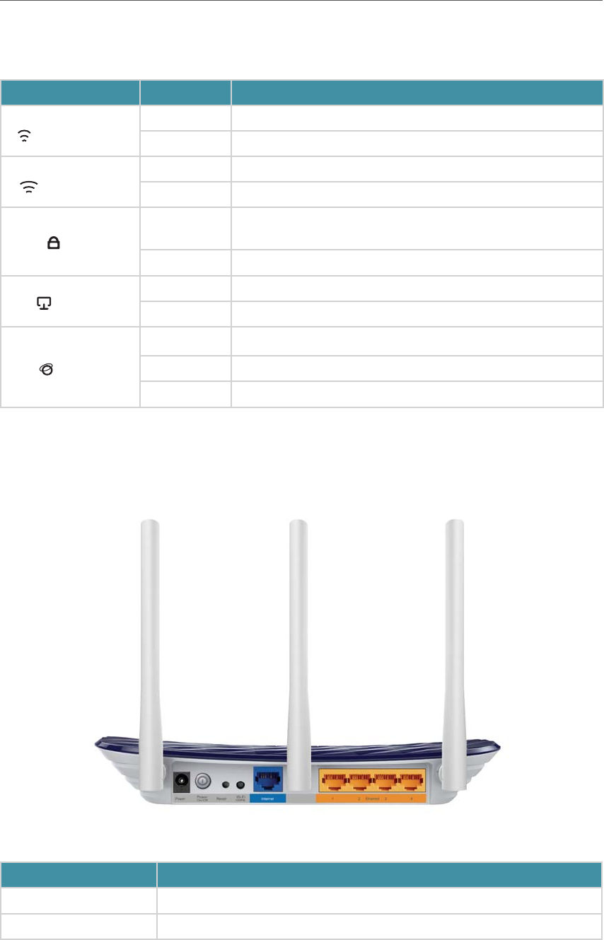
1. 2. 2. The Back Panel
The following parts (view from left to right) are located on the back panel.
Item Description
Power Port For connecting the router to a power socket via the provided power adapter.
Power On/Off Button Press this button to power on or off the router.

5
Chapter 1 Get to Know About Your Router
Item Description
Reset Button Press and hold this button until all the LEDs turn off to reset the router to its factory
default settings.
Wi-Fi/WPS Button
Press this button, and immediately press the WPS button on your device. The WPS
LED of the router should change from flashing to solid on, indicating successful WPS
connection.
Press and hold this button for about 5 seconds to turn on or off the wireless function
of your router.
WAN Port For connecting to a DSL/Cable modem, or an Ethernet port.
Ethernet Ports (1/2/3/4) For connecting your PCs or other wired network devices to the router.
Antennas Used for wireless operation and data transmitting. Upright them for the best Wi-Fi
performance.

Chapter 2
Connect Your Router
This chapter contains the following sections:
• Position Your Router
• Connect Your Router
7
Chapter 2 Connect Your Router
2. 1. Position Your Router
• The product should not be located in a place where it will be exposed to moisture or
excessive heat.
• Place the router in a location where it can be connected to multiple devices as well as
to a power source.
• Make sure the cables and power cord are safely placed out of the way so they do not
create a tripping hazard.
• The router can be placed on a shelf or desktop.
• Keep the router away from strong devices with strong electromagnetic interference,
such as Bluetooth devices, cordless phones and microwaves.
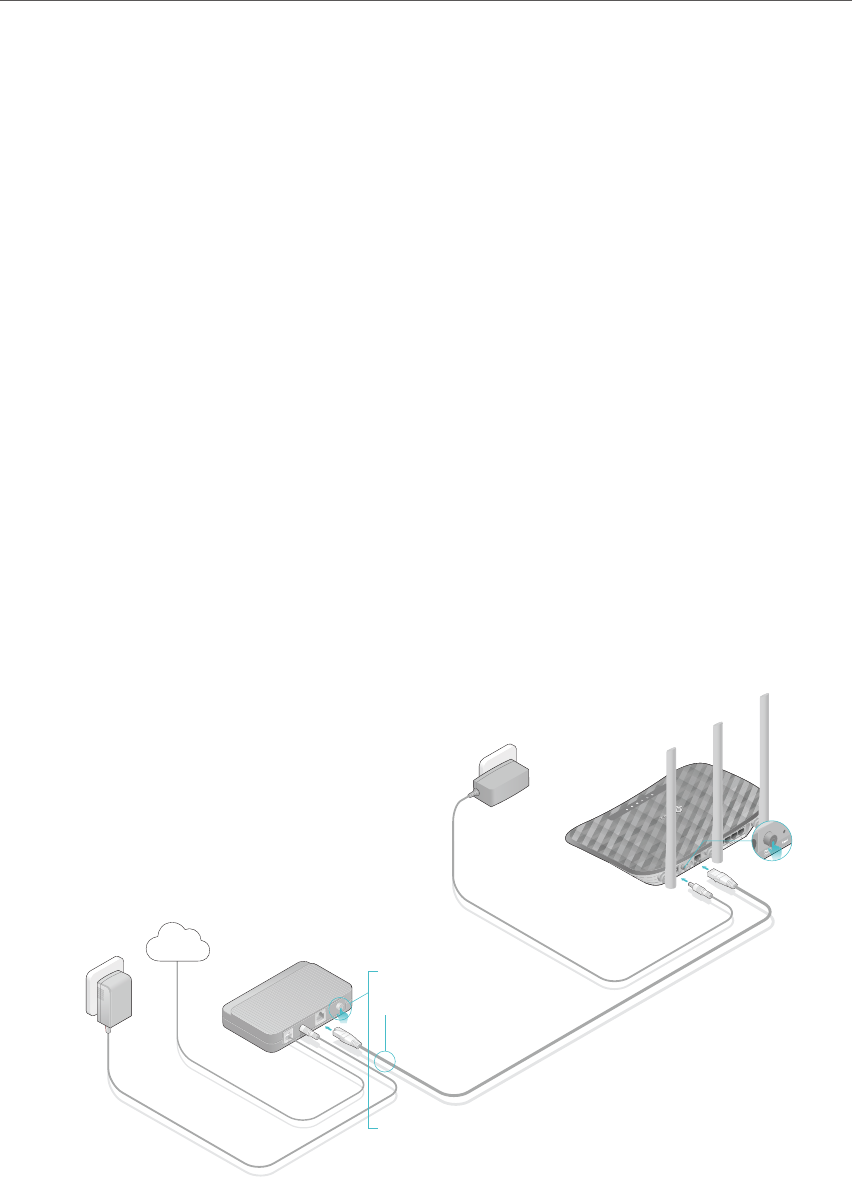
2. 2. Connect Your Router
This mode enables multiple users to share internet connection via ADSL/Cable Modem.
1. Follow the steps below to connect your router.
If your internet connection is through an Ethernet cable directly from the wall instead
of through a DSL / Cable / Satellite modem, connect the Ethernet cable to the router’s
WAN port, and then follow Step 4 and 5 to complete the hardware connection.
Router
Modem
Power adapter
Power adapter
Internet
4
1
2
3
1 ) Turn off the modem, and remove the backup battery if it has one.
2 ) Connect the modem to the Internet port on your router with an Ethernet cable.
3 ) Turn on the modem, and then wait about 2 minutes for it to restart.
8
Chapter 2 Connect Your Router
4 ) Connect the power adapter to the router and turn on the router.
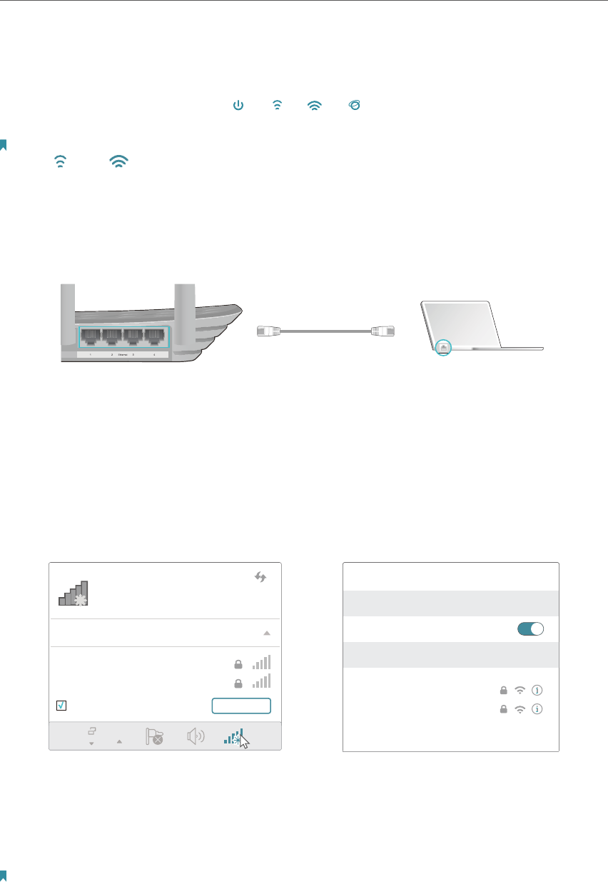
5 ) Verify that the hardware connection is correct by checking these LEDs.
Power
On
5G
On On
Internet
2.4G
On
Note:
If the 2.4G and 5G Wi-Fi LEDs are off, press and hold the Wi-Fi/WPS button on the rear panel for about 5 seconds,
then release the button. Both LEDs will turn on.
2. Connect your computer to the router.
• Method 1: Wired
Turn off the Wi-Fi on your computer and connect the devices as shown below.
Ethernet cable
• Method 2: Wirelessly
1 ) Find the SSID (Network Name) and Wireless Password printed on the label at
the bottom of the router.
2 ) Click the network icon of your computer or go to Wi-Fi Settings of your smart
device, and then select the SSID to join the network.
OR
C
onnections are available
Wireless Network
C
onnectio
n
Connect automatically Connect
TP-Link_XXXX
TP-Link_XXXX_5G
Wi-Fi
Wi-Fi
TP-Link_XXXX
TP-Link_XXXX_5G
CHOOSE A NETWORK...
Other...
< Settings
Smart DeviceComputer
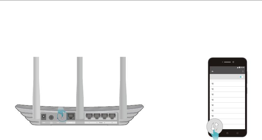
• Method 3: Use the WPS button
Wireless devices that support WPS, including Android phones, tablets and most USB
network cards, can be connected to your router through this method ( Not supported
by iOS devices).
Note:
The WPS function cannot be configured if the wireless function of the router is disabled. Also, the WPS function will be
disabled if your wireless encryption is WEP. Please make sure the wireless function is enabled and is configured with the
appropriate encryption before configuring the WPS.
9
Chapter 2 Connect Your Router
1 ) Tab the WPS icon on the device’s screen. Here takes an Android phone as an
example.
2 ) Immediately press the WPS button on your router.
Wi-Fi
/WPS
WLAN
On
TP-Link_2017
TP-Link_Home
My Home
My Network
Home Network
TP-Link_Network
TP-Link_Test
4G
Close to

Chapter 3
Log In
This chapter introduces how to log in to the web management page of router.
11
Chapter 3 Log In
With the web management page, it is easy to configure and manage the router. The web
management page can be used on any Windows, Macintosh or UNIX OS with a Web
browser, such as Microsoft the Internet Explorer, Mozilla Firefox or Apple Safari.
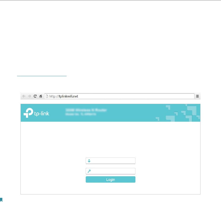
Follow the steps below to log in to your router.
1. Set up the TCP/IP Protocol in Obtain an IP address automatically mode on your
computer.
2. Visit http://tplinkwifi.net, and log in with the username and password you set for the
router. The default one is admin (all lowercase) for both username and password.
Note:
If the login window does not appear, please refer to the FAQ section.

Chapter 4
Configure the Router
This chapter presents how to configure the various features of the router.
It contains the following sections:
• Status
• Quick Setup
• Operation Mode
• Network
• Dual Band Selection
• Wireless(2.4GHz or 5GHz)
• Guest Network
• DHCP
• Forwarding
• Security
• Parental Controls
• Access Control
• Advanced Routing
• Bandwidth Control
• IP&MAC Binding
• Dynamic DNS
• IPv6
• System Tools
• Log Out
13
Chapter 4 &RQƮJXUHWKH5RXWHU
4. 1. Status
1. Visit http://tplinkwifi.net, and log in with the username and password you set for the
router.
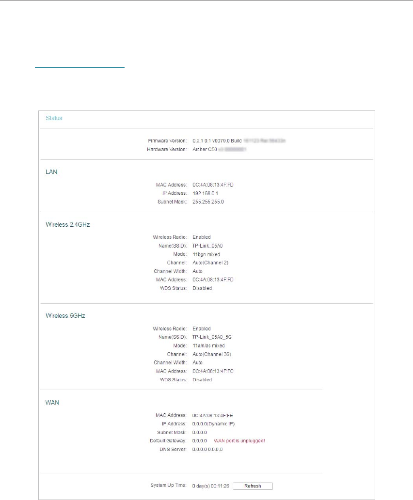
2. Go to Status. You can view the current status information of the router.
• Firmware Version - The version information of the router’s firmware.
• Hardware Version - The version information of the router’s hardware.
• LAN - This field displays the current settings of the LAN, and you can configure them
on the Network > LAN page.
• MAC address - The physical address of the router.
• IP address - The LAN IP address of the router.
• Subnet Mask - The subnet mask associated with the LAN IP address.
• Wireless 2.4GHz/5GHz - This field displays the basic information or status of the
wireless function, and you can configure them on the Wireless > Basic Settings page.

14
Chapter 4 &RQƮJXUHWKH5RXWHU
• Operation Mode - The current wireless working mode in use.
• Wireless Radio - Indicates whether the wireless radio feature of the router is
enabled or disabled.
• Name(SSID) - The SSID of the Router.
• Mode - The current wireless mode which the router works on.
• Channel - The current wireless channel in use.
• Channel Width - The current wireless channel width in use.
• MAC Address - The physical address of the router.
• WAN - This field displays the current settings of the WAN, and you can configure them
on the Network > WAN page.
• MAC Address - The physical address of the WAN port.
• IP Address - The current WAN (Internet) IP Address. This field will be blank
or 0.0.0.0 if the IP Address is assigned dynamically and there is no internet
connection.
• Subnet Mask - The subnet mask associated with the WAN IP Address.
• Default Gateway - The Gateway currently used is shown here. When you use
Dynamic IP as the internet connection type, click Renew or Release here to
obtain new IP parameters dynamically from the ISP or release them.
• DNS Server - The IP addresses of DNS (Domain Name System) server.
• System Up Time - The length of the time since the router was last powered on or
reset.
Click Refresh to get the latest status and settings of the router.
4. 2. Quick Setup
1. Visit http://tplinkwifi.net, and log in with the username and password you set for the
router.
2. Go to Quick Setup.
3. Click Next to start. Then follow the step-by-step instructions to connect your router
to the internet.

15
Chapter 4 &RQƮJXUHWKH5RXWHU
4. 3. Operation Mode
The router supports three operation modes: Wireless Router mode, Access Point mode
and Range Extender.
4. 3. 1. Wireless Router Mode
The default Wireless Router mode is required most commonly. In this mode, the device
enables multiple users to share the internet connection via ADSL/Cable Modem.
For hardware connection, refer to Connect Your Router.
4. 3. 2. Access Point Mode
In this mode, the device can be connected to a wired network and transform the wired
access into wireless one. If you already have a wired router, you can use this mode.
Refer to Configure the Router in Access Point Mode session for detailed information.
4. 3. 3. Range Extender Mode
In this mode, the device can copy and reinforce the existing wireless signal to extend
the coverage of the signal, especially for a large space to eliminate signal-blind corners.
Refer to Configure the Router in Range Extender Mode session for detailed information.
4. 4. Network
4. 4. 1. WAN
1. Visit http://tplinkwifi.net, and log in with the username and password you set for the
router.
2. Go to Network > WAN.
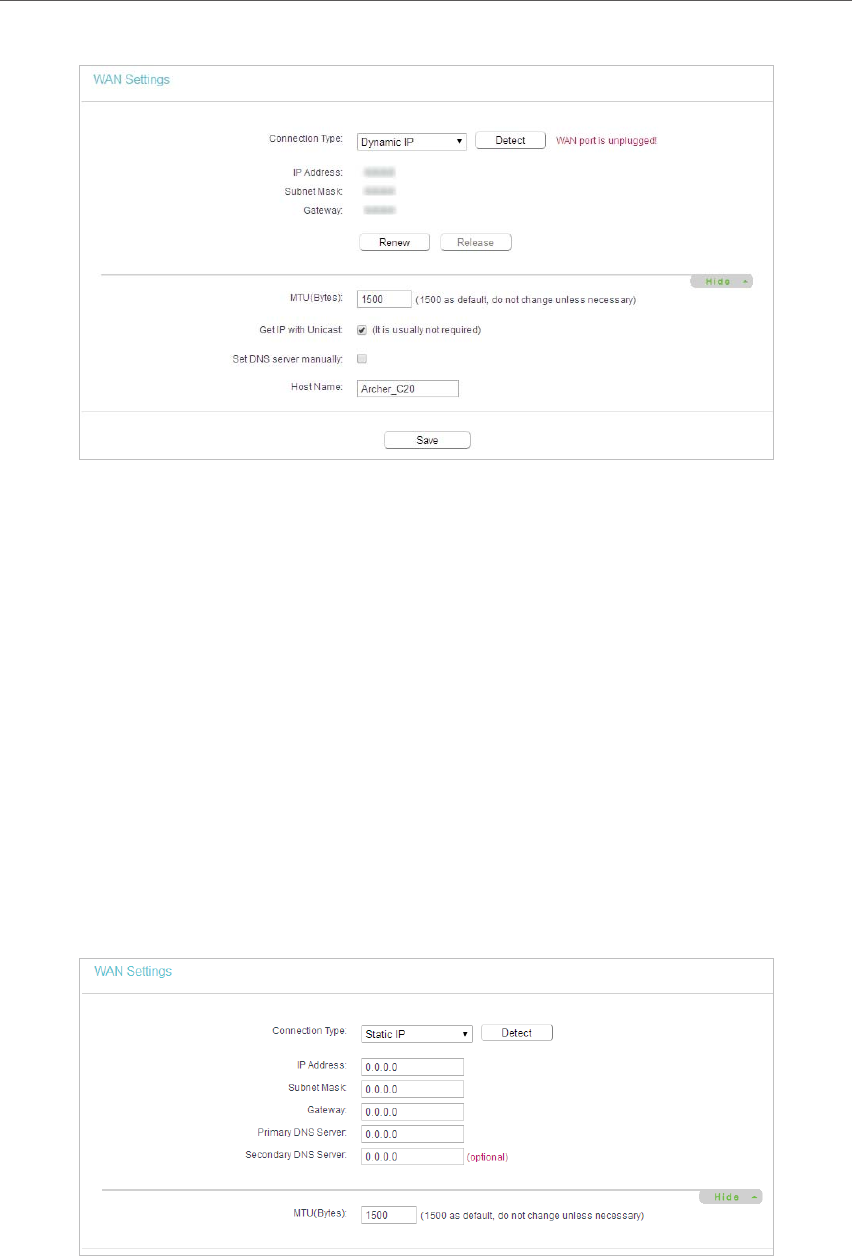
3. Configure the IP parameters of the WAN and click Save.
Dynamic IP
If your ISP provides the DHCP service, please select Dynamic IP, and the router will
automatically get IP parameters from your ISP.
Click Renew to renew the IP parameters from your ISP.
Click Release to release the IP parameters.
16
Chapter 4 &RQƮJXUHWKH5RXWHU
• MTU(Bytes) - The normal MTU (Maximum Transmission Unit) value for most Ethernet
networks is 1500 Bytes. It is not recommended that you change the default MTU size
unless required by your ISP.
• Get IP with Unicast - A few ISPs’ DHCP servers do not support the broadcast
applications. If you cannot get the IP address normally, you can choose this option. (It
is rarely required.)
• Set DNS server manually - If your ISP gives you one or two DNS addresses, select Set
DNS server manually and enter the primary and secondary addresses into the correct
fields. Otherwise, the DNS servers will be assigned automatically from your ISP.
• Host Name -This option specifies the name of the router.
Static IP
If your ISP provides a static or fixed IP address, subnet mask, default gateway and DNS
setting, please select Static IP.
• IP Address - Enter the IP address in dotted-decimal notation provided by your ISP.
• Subnet Mask - Enter the subnet mask in dotted-decimal notation provided by your
ISP. Normally 255.255.255.0 is used as the subnet mask.
17
Chapter 4 &RQƮJXUHWKH5RXWHU
• Gateway - Enter the gateway IP address in dotted-decimal notation provided by your
ISP.
• Primary/Secondary DNS Server - Enter one or two DNS addresses in dotted-decimal
notation provided by your ISP. For the Secondary DSN Server, it is optional.
• MTU (Bytes) - The normal MTU (Maximum Transmission Unit) value for most Ethernet
networks is 1500 Bytes. It is not recommended that you change the default MTU size
unless required by your ISP.
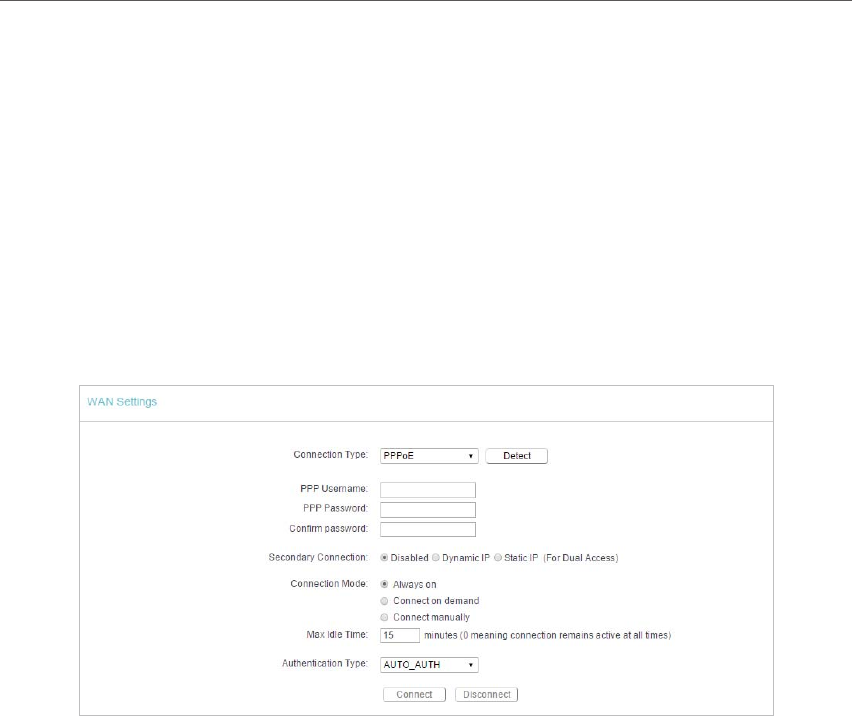
PPPoE
If your ISP provides PPPoE connection, select PPPoE.
• PPP Username/Password - Enter the user name and password provided by your ISP.
These fields are case-sensitive.
• Confirm Password - Enter the Password provided by your ISP again to ensure the
password you entered is correct.
• Secondary Connection - It’s available only for PPPoE connection. If your ISP provides
an extra connection type, select Dynamic IP or Static IP to activate the secondary
connection.
• Connection Mode
• Always On - In this mode, the internet connection will be active all the time.
• Connect on Demand - In this mode, the internet connection can be terminated
automatically after a specified inactivity period (Max Idle Time) and be re-
established when you attempt to access the internet again. If you want to keep
your internet connection active all the time, please enter 0 in the Max Idle Time
field. Otherwise, enter the number of minutes you want to have elapsed before
your internet access disconnects.
• Connect Manually - You can click Connect/Disconnect to connect/disconnect
immediately. This mode also supports the Max Idle Time function as Connect
on Demand mode. The internet connection can be disconnected automatically
18
Chapter 4 &RQƮJXUHWKH5RXWHU
after a specified inactivity period (Max Idle Time) and not be able to re-establish
when you attempt to access the internet again.
• Authentication Type - Choose an authentication type.
Note:
• Sometimes the connection cannot be terminated although you have specified the Max Idle Time because
some applications are visiting the internet continually in the background.
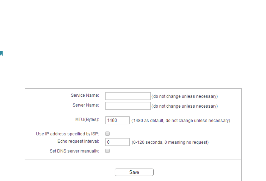
If you want to do some advanced configurations, please click Advanced.
• Service Name/Server Name - The service name and server name should not be
configured unless you are sure it is necessary for your ISP. In most cases, leaving
these fields blank will work.
• MTU(Bytes) - The default MTU size is 1480 bytes. It is not recommended that you
change the default MTU size unless required by your ISP.
• ISP Specified IP Address - If your ISP does not automatically assign IP addresses to
the router, please select Use IP address specified by ISP and enter the IP address
provided by your ISP in dotted-decimal notation.
• Echo request interval - The router will detect Access Concentrator online at every
interval. The default value is 0. You can input the value between 0 and 120. The value
0 means no detect.
• DNS Server/Secondary DNS Server - If your ISP does not automatically assign DNS
addresses to the router, please select Set DNS server manually and enter the IP
address in dotted-decimal notation of your ISP’s primary DNS server. If a secondary
DNS server address is available, enter it as well.
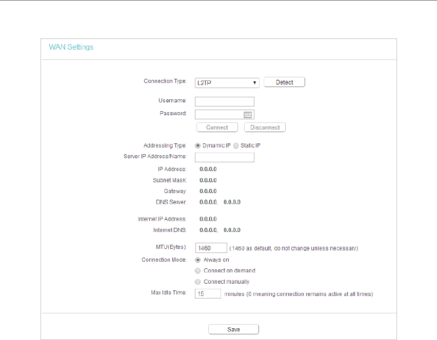
L2TP
If your ISP provides L2TP connection, please select L2TP.
19
Chapter 4 &RQƮJXUHWKH5RXWHU
• Username/Password - Enter the user name and password provided by your ISP. These
fields are case-sensitive.
• Addressing Type - Choose the addressing type given by your ISP, either Dynamic IP
or Static IP. Click the Connect button to connect immediately. Click the Disconnect
button to disconnect immediately.
• Server IP Address/Name - Enter server IP address or domain name provided by your
ISP.
• MTU(Bytes) - The default MTU size is “1460” bytes, which is usually fine. It is not
recommended that you change the default MTU Size unless required by your ISP.
• Connection Mode
• Always On - In this mode, the internet connection will be active all the time.
• Connect on Demand - In this mode, the internet connection can be terminated
automatically after a specified inactivity period (Max Idle Time) and be re-
established when you attempt to access the internet again. If you want to keep
your internet connection active all the time, please enter 0 in the Max Idle Time
field. Otherwise, enter the number of minutes you want to have elapsed before
your internet access disconnects.
• Connect Manually - You can click Connect/Disconnect to connect/disconnect
immediately. This mode also supports the Max Idle Time function as Connect
on Demand mode. The internet connection can be disconnected automatically
20
Chapter 4 &RQƮJXUHWKH5RXWHU
after a specified inactivity period (Max Idle Time) and not be able to re-establish
when you attempt to access the internet again.
Note:
Sometimes the connection cannot be terminated although you have specified the Max Idle Time because some
applications are visiting the internet continually in the background.
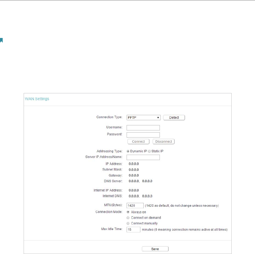
PPTP
If your ISP provides PPTP connection, please select PPTP.
• Username/Password - Enter the user name and password provided by your ISP. These
fields are case-sensitive.
• Addressing Type - Choose the addressing type given by your ISP, either Dynamic IP
or Static IP. Click the Connect button to connect immediately. Click the Disconnect
button to disconnect immediately.
• Server IP Address/Name - Enter server IP address or domain name provided by your
ISP.
• MTU(Bytes) - The default MTU size is “1420” bytes, which is usually fine. It is not
recommended that you change the default MTU Size unless required by your ISP.
• Connection Mode
• Always On - In this mode, the internet connection will be active all the time.
• Connect on Demand - In this mode, the internet connection can be terminated
automatically after a specified inactivity period (Max Idle Time) and be re-
established when you attempt to access the internet again. If you want to keep
your internet connection active all the time, please enter 0 in the Max Idle Time
21
Chapter 4 &RQƮJXUHWKH5RXWHU
field. Otherwise, enter the number of minutes you want to have elapsed before
your internet access disconnects.
• Connect Manually - You can click Connect/Disconnect to connect/disconnect
immediately. This mode also supports the Max Idle Time function as Connect
on Demand mode. The internet connection can be disconnected automatically
after a specified inactivity period (Max Idle Time) and not be able to re-establish
when you attempt to access the internet again.
Note:
Sometimes the connection cannot be terminated although you have specified the Max Idle Time because some
applications are visiting the internet continually in the background.
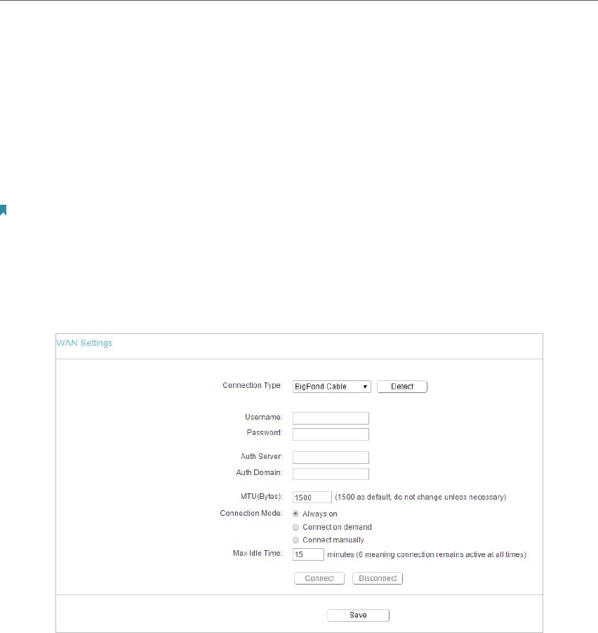
BigPond Cable
If your ISP provides BigPond cable connection, please select BigPond Cable.
• Username/Password - Enter the use name and password provided by your ISP. These
fields are case-sensitive.
• Auth Server - Enter the authenticating server IP address or host name.
• Auth Domain - Type in the domain suffix server name based on your location.
• MTU(Bytes) - The default MTU size is 1500 bytes. It is not recommended that you
change the default MTU size unless required by your ISP.
• Connection Mode
• Always On - In this mode, the internet connection will be active all the time.
• Connect on Demand - In this mode, the internet connection can be terminated
automatically after a specified inactivity period (Max Idle Time) and be re-
established when you attempt to access the internet again. If you want to keep
your internet connection active all the time, please enter 0 in the Max Idle Time
22
Chapter 4 &RQƮJXUHWKH5RXWHU
field. Otherwise, enter the number of minutes you want to have elapsed before
your internet access disconnects.
• Connect Manually - You can click Connect/Disconnect to connect/disconnect
immediately. This mode also supports the Max Idle Time function as Connect
on Demand mode. The internet connection can be disconnected automatically
after a specified inactivity period (Max Idle Time) and not be able to re-establish
when you attempt to access the internet again.
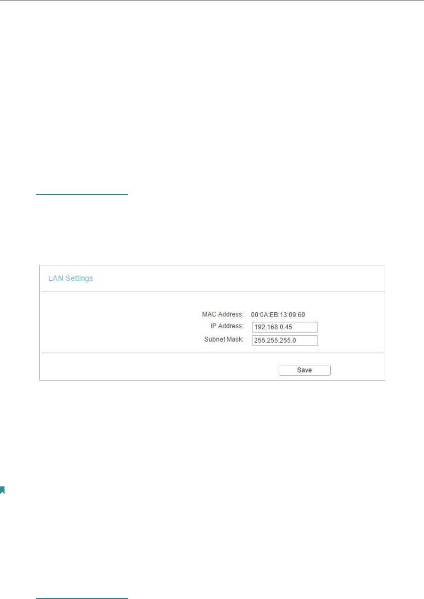
4. 4. 2. LAN
1. Visit http://tplinkwifi.net, and log in with the username and password you set for the
router.
2. Go to Network > LAN.
3. Configure the IP parameters of the LAN and click Save.
• MAC Address - The physical address of the LAN ports. The value can not be changed.
• IP Address - Enter the IP address in dotted-decimal notation of your router (factory
default - 192.168.0.254).
• Subnet Mask - An address code that determines the size of the network. Normally
255.255.255.0 is used as the subnet mask.
Note:
• If you have changed the IP address, you must use the new IP address to log in.
• If the new IP address you set is not in the same subnet as the old one, the IP address pool in the DHCP
Server will be configured automatically, but the Virtual Server and DMZ Host will not take effect until they
are re-configured.
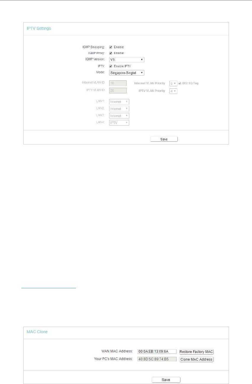
4. 4. 3. IPTV
1. Visit http://tplinkwifi.net, and log in with the username and password you set for the
router.
2. Go to Network > IPTV.
3. Configure the IPTV settings and click Save.
23
Chapter 4 &RQƮJXUHWKH5RXWHU
• IGMP Snooping - IGMP snooping is designed to prevent hosts on a local network from
receiving traffic for a multicast group they have not explicitly joined. IGMP snooping
is especially useful for bandwidth-intensive IP multicast applications such as IPTV.
• IGMP Proxy - Select to enable IGMP Proxy.
• IGMP Version - Select the IGMP(Internet Group Management Protocol) Proxy Version,
either V2 or V3, according to your ISP.
• IPTV - Select to enable the IPTV feature.
• Mode - Select the appropriate mode according to your ISP.
• LAN 1/2/3/4 - Assign your LAN port to whether function as the Internet supplier or as
the IPTV supplier.
4. 4. 4. MAC Clone
1. Visit http://tplinkwifi.net, and log in with the username and password you set for the
router.
2. Go to Network > MAC Clone.
3. Configure the WAN MAC address and click Save.
24
Chapter 4 &RQƮJXUHWKH5RXWHU
• WAN MAC Address - This field displays the current MAC address of the WAN port.
If your ISP requires you to register the MAC address, please enter the correct MAC
address in this field. Click Restore Factory MAC to restore the MAC address of WAN
port to the factory default value.
• Your PC’s MAC Address - This field displays the MAC address of the PC that is
managing the router. If the MAC address is required, you can click Clone MAC Address
and this MAC address will be filled in the WAN MAC Address field.
Note:
• You can only use the MAC Address Clone function for PCs on the LAN.
• If you have changed the WAN MAC address when the WAN connection is PPPoE, it will not take effect
until the connection is re-established.
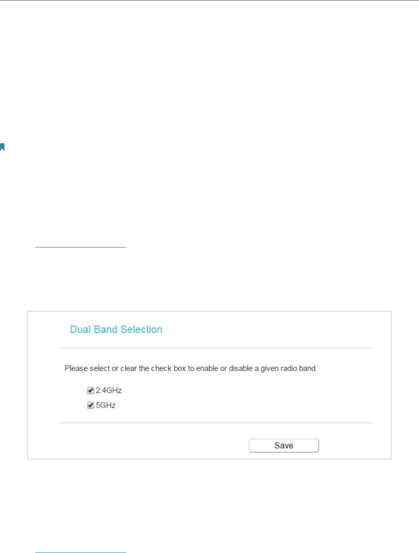
4. 5. Dual Band Selection
1. Visit http://tplinkwifi.net, and log in with the username and password you set for the
router.
2. Go to Dual Band Selection.
3. Select the working radio band as needed and click Save.
4. 6. Wireless(2.4GHz or 5GHz)
4. 6. 1. Wireless Settings
1. Visit http://tplinkwifi.net, and log in with the username and password you set for the
router.
2. Go to Wireless > Basic Settings.
3. Configure the basic settings for the wireless network and click Save.

25
Chapter 4 &RQƮJXUHWKH5RXWHU
• Wireless - Enable or disable wireless network.
• Wireless Network Name - Enter a value of up to 32 characters. The same Name (SSID)
must be assigned to all wireless devices in your network.
• Mode - You can choose the appropriate “Mixed” mode.
• Channel - This field determines which operating frequency will be used. The default
channel is set to Auto. It is not necessary to change the wireless channel unless you
notice interference problems with another nearby access point.
• Channel Width - This field determines which operating frequency will be used. It is not
necessary to change the wireless channel unless you notice interference problems
with another nearby access point. If you select auto, then AP will choose the best
channel automatically.
• Enable SSID Broadcast - If enabled, the router will broadcast the wireless network
name (SSID).
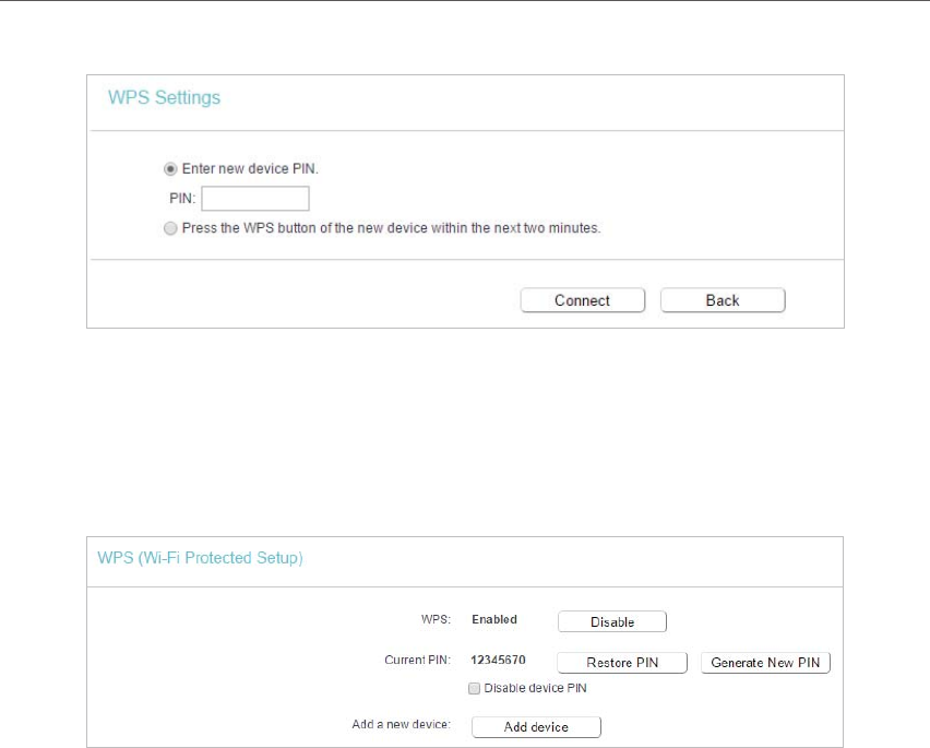
4. 6. 2. WPS
WPS (Wi-Fi Protected Setup) can help you to quickly and securely connect to a network.
This section will guide you to add a new wireless device to your router’s network quickly
via WPS.
Note:
The WPS function cannot be configured if the wireless function of the router is disabled. Please make sure the wireless
function is enabled before configuration.
1. Visit http://tplinkwifi.net, and log in with the username and password you set for the
router.
2. Go to Wireless > WPS.
3. Follow one of the following three methods to connect your client device to the
router’s Wi-Fi network.
Method ONE: Press the WPS Buttons on the Router and Client Device
For details, refer to Method 3: Use the WPS button of Connect Your Router.
26
Chapter 4 &RQƮJXUHWKH5RXWHU
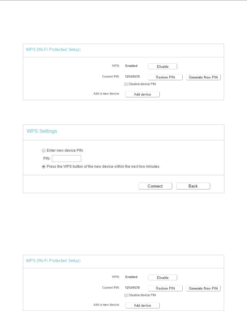
Method TWO: Press the WPS Button on Your Client Device
1. Keep the WPS Status as Enabled and click Add Device.
2. Select Press the WPS button of the new device within the next two minutes and click
Connect.
3. Within two minutes, press the WPS button on your client device.
4. A success message will appear on the WPS page if the client device has been
successfully added to the router’s network.
Method THREE: Enter the Client’s PIN
1. Keep the WPS Status as Enabled and click Add Device.
2. Select Enter new device PIN, enter your client device’s current PIN in the PIN filed and
click Connect.
27
Chapter 4 &RQƮJXUHWKH5RXWHU
3. A success message will appear on the WPS page if the client device has been
successfully added to the router’s network.
Method FOUR: Enter the Router’s PIN
1. Keep the WPS Status as Enabled and get the Current PIN of the router.
2. Enter the router’s current PIN on your client device to join the router’s Wi-Fi network.
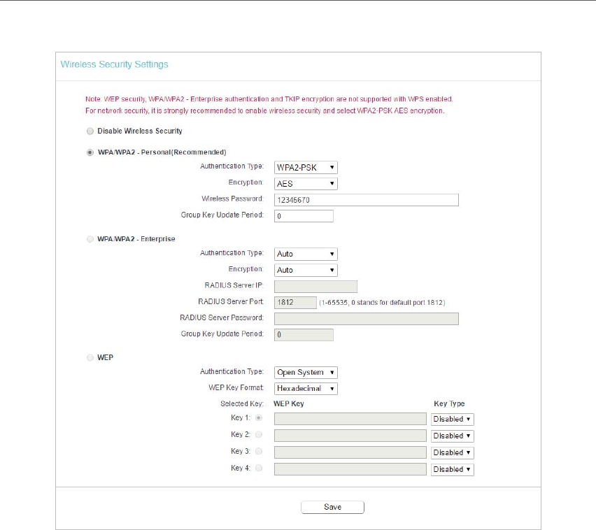
4. 6. 3. Wireless Security
1. Visit http://tplinkwifi.net, and log in with the username and password you set for the
router.
2. Go to Wireless > Wireless Security.
3. Configure the security settings of your wireless network and click Save.
28
Chapter 4 &RQƮJXUHWKH5RXWHU
• Disable Wireless Security - The wireless security function can be enabled or disabled.
If disabled, wireless clients can connect to the router without a password. It’s strongly
recommended to choose one of the following modes to enable security.
• WPA-PSK/WPA2-Personal - It’s the WPA/WPA2 authentication type based on pre-
shared passphrase.
• Authentication Type - Select Auto, WPA-PSK or WPA2-PSK.
• Encryption - Select Auto, TKIP or AES.
• Wireless Password - Enter ASCII or Hexadecimal characters. For Hexadecimal,
the length should be between 8 and 64 characters; for ASCII, the length should
be between 8 and 63 characters.
• Group Key Update Period - Specify the group key update interval in seconds.
The value can be 0 or at least 30. Enter 0 to disable the update.
• WPA /WPA2-Enterprise - It’s based on Radius Server.
• Authentication Type - Select Auto, WPA or WPA2.
• Encryption - Select Auto, TKIP or AES.
• Radius Server IP - Enter the IP address of the Radius server.

29
Chapter 4 &RQƮJXUHWKH5RXWHU
• Radius Server Port - Enter the port that Radius server used.
• Radius Server Password - Enter the password for the Radius server.
• Group Key Update Period - Specify the group key update interval in seconds.
The value should be 30 or above. Enter 0 to disable the update.
• WEP - It is based on the IEEE 802.11 standard.
• Authentication Type - The default setting is Auto, which can select Shared
Key or Open System authentication type automatically based on the wireless
client’s capability and request.
• WEP Key Format - Hexadecimal and ASCII formats are provided here.
Hexadecimal format stands for any combination of hexadecimal digits (0-9,
a-f, A-F) in the specified length. ASCII format stands for any combination of
keyboard characters in the specified length.
• WEP Key (Password) - Select which of the four keys will be used and enter the
matching WEP key. Make sure these values are identical on all wireless clients
in your network.
• Key Type - Select the WEP key length (64-bit or 128-bit ) for encryption. Disabled
means this WEP key entry is invalid.
• 64-bit - Enter 10 hexadecimal digits (any combination of 0-9, a-f and A-F. Null
key is not permitted) or 5 ASCII characters.
• 128-bit - Enter 26 hexadecimal digits (any combination of 0-9, a-f and A-F. Null
key is not permitted) or 13 ASCII characters.
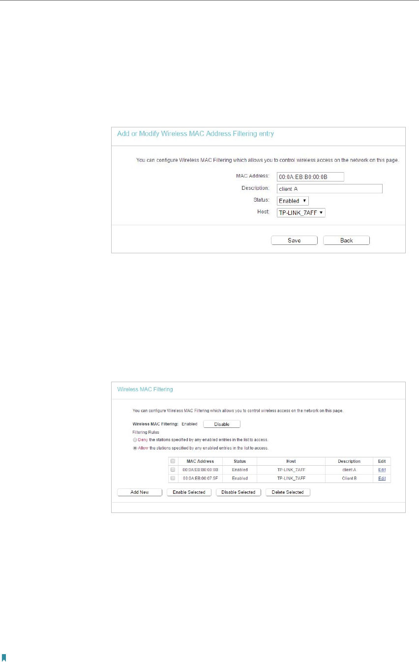
4. 6. 4. Wireless MAC Filtering
Wireless MAC Filtering is used to deny or allow specific wireless client devices to access
your network by their MAC addresses.
Deny or allow specific wireless client devices to access my
network by their MAC addresses.
For example, you want the wireless client A with the MAC
address 00-0A-EB-B0-00-0B and the wireless client B with the
MAC address 00-0A-EB-00-07-5F to access the router, but
other wireless clients cannot access the router
1. Visit http://tplinkwifi.net, and log in with the username and
password you set for the router.
2. Go to Wireless > Wireless MAC Filtering.
I want to:
How
can I do
that?
30
Chapter 4 &RQƮJXUHWKH5RXWHU
3. Click Enable to enable the Wireless MAC Filtering function.
4. Select Allow the stations specified by any enabled entries in
the list to access as the filtering rule.
5. Delete all or disable all entries if there are any entries already.
6. Click Add New and fill in the blank.
1 ) Enter the MAC address 00:0A:EB:B0:00:0B or
00:0A:EB:00:07-5F in the MAC Address field.
2 ) Enter wireless client A/B in the Description field.
3 ) Select Enabled in the Status drop-down list.
4 ) Click Save and click Back.
7. The configured filtering rules should be listed as the picture
shows below.
Now only client A and client B can access your network.
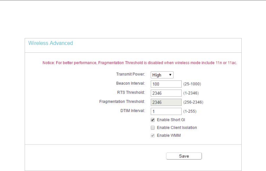
4. 6. 5. Wireless Advanced
1. Visit http://tplinkwifi.net, and log in with the username and password you set for the
router.
2. Go to Wireless > Wireless Advanced.
3. Configure the advanced settings of your wireless network and click Save.
Note:
Done!
31
Chapter 4 &RQƮJXUHWKH5RXWHU
If you are not familiar with the setting items on this page, it’s strongly recommended to keep the provided default values;
otherwise it may result in lower wireless network performance.
• Transmit Power - Select High, Middle or Low which you would like to specify for the
router. High is the default setting and recommended.
• Beacon Interval - Enter a value between 40-1000 milliseconds for Beacon Interval
here. Beacon Interval value determines the time interval of the beacons. The beacons
are the packets sent by the router to synchronize a wireless network. The default
value is 100.
• RTS Threshold - Here you can specify the RTS (Request to Send) Threshold. If the
packet is larger than the specified RTS Threshold size, the router will send RTS frames
to a particular receiving station and negotiate the sending of a data frame. The default
value is 2346.
• Fragmentation Threshold - This value is the maximum size determining whether
packets will be fragmented. Setting a low value for the Fragmentation Threshold may
result in poor network performance because of excessive packets. 2346 is the default
setting and is recommended.
• DTIM Interval - This value determines the interval of the Delivery Traffic Indication
Message (DTIM). A DTIM field is a countdown field informing clients of the next window
for listening to broadcast and multicast messages. When the router has buffered
broadcast or multicast messages for associated clients, it sends the next DTIM with
a DTIM Interval value. You can specify the value between 1-255 Beacon Intervals. The
default value is 1, which indicates the DTIM Interval is the same as Beacon Interval.
• Enable Short GI - It is recommended to enable this function, for it will increase the
data capacity by reducing the guard interval time.
32
Chapter 4 &RQƮJXUHWKH5RXWHU
• Enable Client Isolation - This function isolates all connected wireless stations so that
wireless stations cannot access each other through WLAN.
• Enable WMM - WMM function can guarantee the packets with high-priority messages
being transmitted preferentially. It is strongly recommended to enable this function.
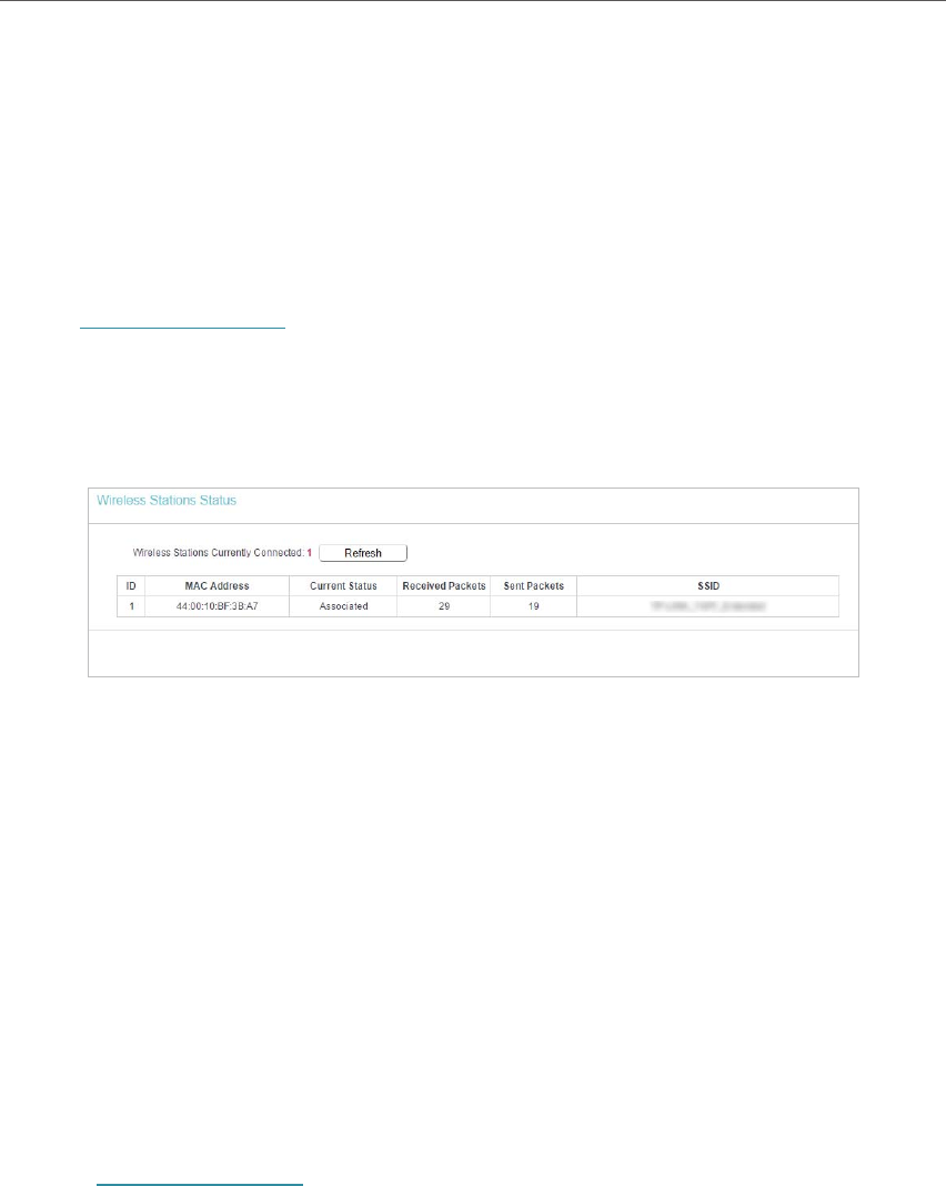
4. 6. 6. Wireless Statistics
1. Visit http://tplinkwifi.net, and log in with the username and password you set for the
router.
2. Go to Wireless > Wireless Statistics to check the data packets sent and received by
each client device connected to the router.
• MAC Address - The MAC address of the connected wireless client.
• Current Status - The running status of the connected wireless client.
• Received Packets - Packets received by the wireless client.
• Sent Packets - Packets sent by the wireless client.
• SSID - SSID that the station associates with.
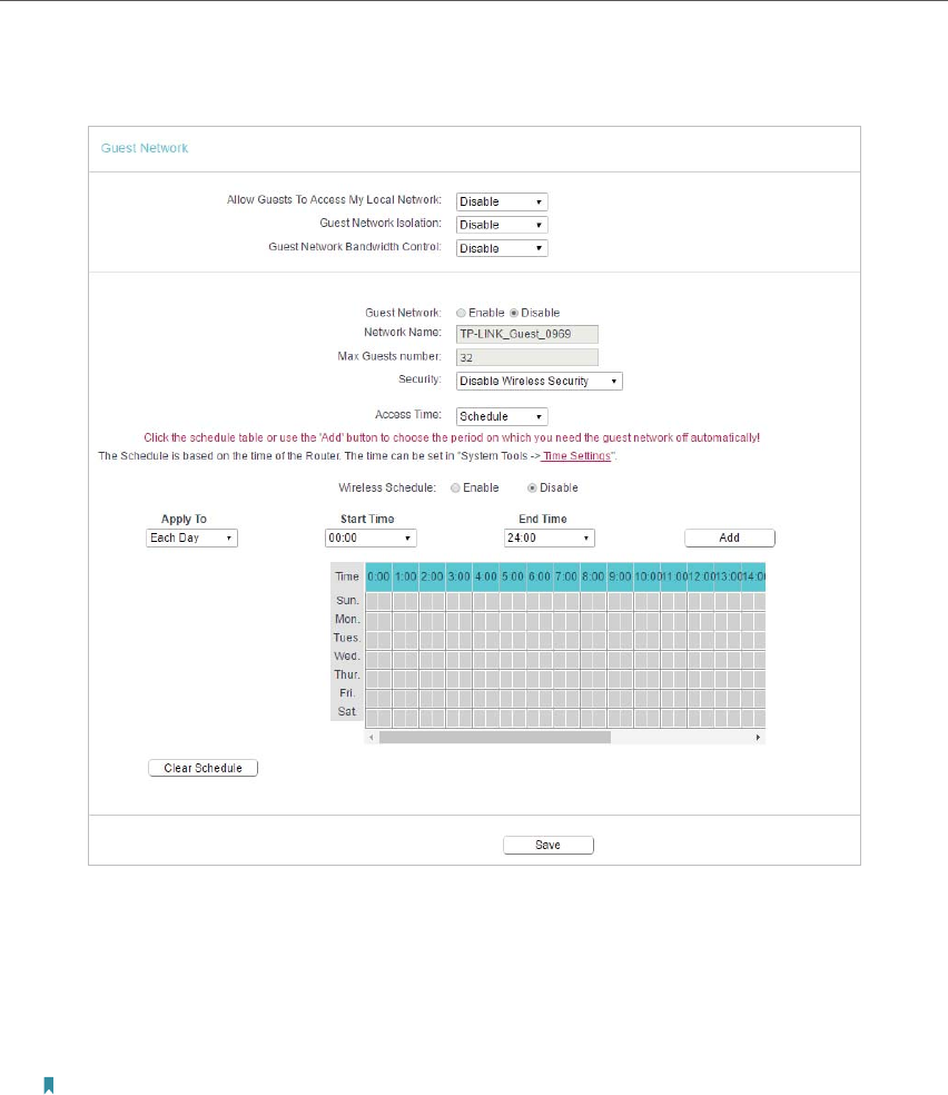
4. 7. Guest Network
Guest Network allows you to provide Wi-Fi access for guests without disclosing your
host network. When you have guests in your house, apartment, or workplace, you can
create a guest network for them. In addition, you can customize guest network settings
to ensure network security and privacy.
1. Visit http://tplinkwifi.net, and log in with the username and password you set for the
router.
2. Go to Guest Network.
3. Enable the Guset Network function.
4. Create a network name for your guest network.
5. Select the Security type and create the Password of the guest network.
6. Select Schedule from the Access Time drop-down list and customize it for the
guest network.
33
Chapter 4 &RQƮJXUHWKH5RXWHU
7. Click Save.
• Allow Guest To Access My Local Network - If enabled, guests can access the
local network and manage it.
• Guest Network Isolation - If enabled, guests are isolated from each other.
• Enable Guest Network Bandwidth Control - If enabled, the Guest Network
Bandwidth Control rules will take effect.
Note: The range of bandwidth for guest network is calculated according to the setting of Bandwidth Control on
the Bandwidth Control page.
4. 8. DHCP
By default, the DHCP (Dynamic Host Configuration Protocol) Server is enabled and the
router acts as a DHCP server; it dynamically assigns TCP/IP parameters to client devices
from the IP Address Pool. You can change the settings of DHCP Server if necessary,
and you can reserve LAN IP addresses for specified client devices.
34
Chapter 4 &RQƮJXUHWKH5RXWHU
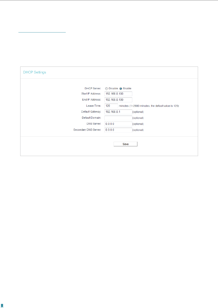
4. 8. 1. DHCP Settings
1. Visit http://tplinkwifi.net, and log in with the username and password you set for the
router.
2. Go to DHCP > DHCP Settings.
3. Specify DHCP server settings and click Save.
• DHCP Server - Enable or disable the DHCP server. If disabled, you must have another
DHCP server within your network or else you must configure the computer manually.
• Start IP Address - Specify an IP address for the DHCP Server to start with when
assigning IP addresses. 192.168.0.100 is the default start address.
• End IP Address - Specify an IP address for the DHCP Server to end with when assigning
IP addresses. 192.168.0.199 is the default end address.
• Address Lease Time - The Address Lease Time is the amount of time a network user
will be allowed to connect to the router with the current dynamic IP Address. When
time is up, the user will be automatically assigned a new dynamic IP address. The
range of the time is 1 ~ 2880 minutes. The default value is 120.
• Default Gateway (Optional) - It is suggested to input the IP address of the LAN port of
the router. The default value is 192.168.0.1.
• Default Domain (Optional) - Input the domain name of your network.
• DNS Server (Optional) - Input the DNS IP address provided by your ISP.
• Secondary DNS Server (Optional) - Input the IP address of another DNS server if your
ISP provides two DNS servers.
Note:
• To use the DHCP server function of the router, you must configure all computers on the LAN as Obtain
an IP Address automatically.
35
Chapter 4 &RQƮJXUHWKH5RXWHU
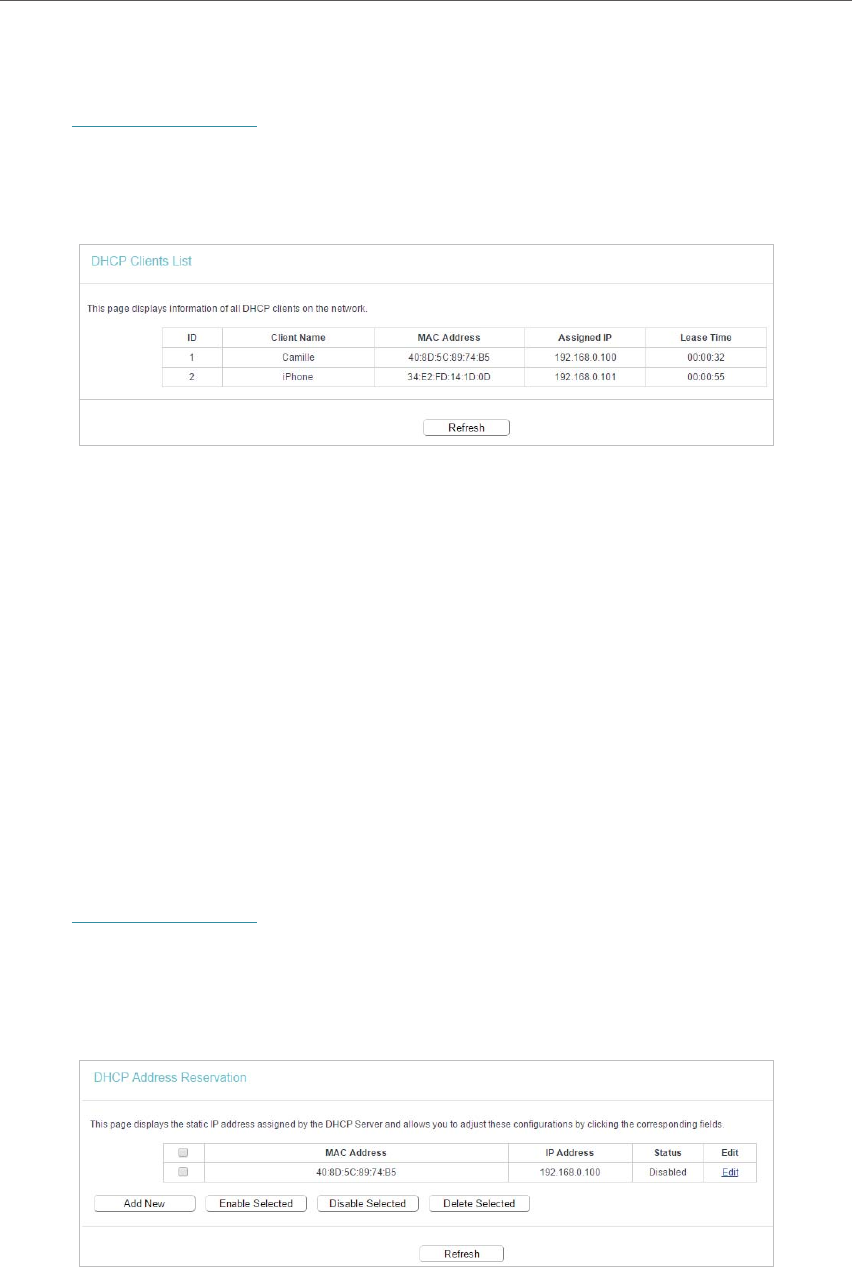
4. 8. 2. DHCP Client List
1. Visit http://tplinkwifi.net, and log in with the username and password you set for the
router.
2. Go to DHCP > DHCP Client List to view the information of the clients connected to
the router.
• Client Name - The name of the DHCP client.
• MAC Address - The MAC address of the DHCP client.
• Assigned IP - The IP address that the outer has allocated to the DHCP client.
• Lease Time - The time of the DHCP client leased. After the dynamic IP address has
expired, a new dynamic IP address will be automatically assigned to the user.
You cannot change any of the values on this page. To update this page and show the
current attached devices, click Refresh.
4. 8. 3. Address Reservation
You can reserve an IP address for a specific client. When you specify a reserved IP
address for a PC on the LAN, this PC will always receive the same IP address each time
when it accesses the DHCP server.
1. Visit http://tplinkwifi.net, and log in with the username and password you set for the
router.
2. Go to DHCP > Address Reservation.
3. Click Add New and fill in the blank.
1 ) Enter the MAC address (in XX:XX:XX:XX:XX:XX format.) of the client for which
you want to reserve an IP address.

36
Chapter 4 &RQƮJXUHWKH5RXWHU
2 ) Enter the IP address (in dotted-decimal notation) which you want to reserve for
the client.
3 ) Leave the Status as Enabled.
4 ) Click Save.
4. 9. Forwarding
The router’s NAT (Network Address Translation) feature makes the devices on the LAN
use the same public IP address to communicate in the internet, which protects the
local network by hiding IP addresses of the devices. However, it also brings about the
problem that external hosts cannot initiatively communicate with the specified devices
in the local network.
With the forwarding feature, the router can traverse the isolation of NAT so that clients
on the internet can reach devices on the LAN and realize some specific functions.
The TP-Link router includes four forwarding rules. If two or more rules are set, the
priority of implementation from high to low is Virtual Servers, Port Triggering, UPNP and
DMZ.
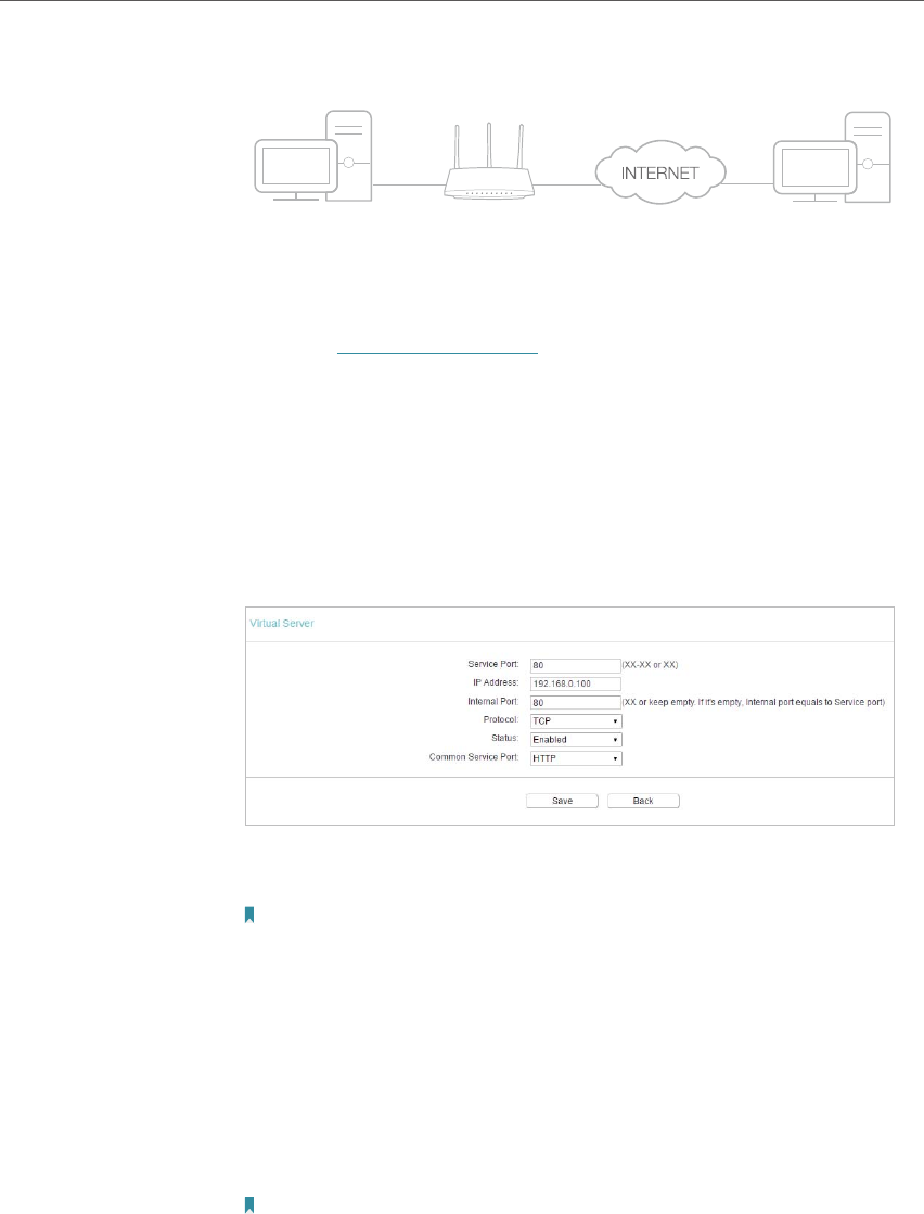
4. 9. 1. Virtual Server
When you build up a server in the local network and want to share it on the internet,
Virtual Servers can realize the service and provide it to internet users. At the same time
virtual servers can keep the local network safe as other services are still invisible from
the internet.
Virtual Servers can be used to set up public services in your local network, such as
HTTP, FTP, DNS, POP3/SMTP and Telnet. Different service uses different service port.
Port 80 is used in HTTP service, port 21 in FTP service, port 25 in SMTP service and port
110 in POP3 service. Please verify the service port number before the configuration.
Share my personal website I’ve built in local network with my
friends through the internet.
For example, the personal website has been built in my home PC
(192.168.0.100). I hope that my friends on the internet can visit
my website in some way. My PC is connected to the router with
the WAN IP address 218.18.232.154.
I want to:
37
Chapter 4 &RQƮJXUHWKH5RXWHU
Router
WAN: 218.18.232.154
LAN
Home
Personal Website
1. Set your PC to a static IP address, for example 192.168.0.100.
2. Visit http://tplinkwifi.net, and log in with the username and
password you set for the router.
3. Go to Forwarding > Virtual Server.
4. Click Add New. Select HTTP from the Common Service
Port list. The service port, internal port and protocol
will be automatically filled in. Enter the PC’s IP address
192.168.0.100 in the IP Address field.
5. Leave the status as Enabled and click Save.
Note:
• It is recommended to keep the default settings of Internal Port and
Protocol if you are not clear about which port and protocol to use.
• If the service you want to use is not in the Common Service Port list, you
can enter the corresponding parameters manually. You should verify the
port number that the service needs.
• You can add multiple virtual server rules if you want to provide several
services in a router. Please note that the Service Port should not be
overlapped.
Users on the internet can enter http:// WAN IP (in this example:
http:// 218.18.232.154) to visit your personal website.
Note:
• If you have changed the default Service Port, you should use http:// WAN
IP: Service Port to visit the website.
• Some specific service ports are forbidden by the ISP. If you fail to visit the
website, please use another service port.
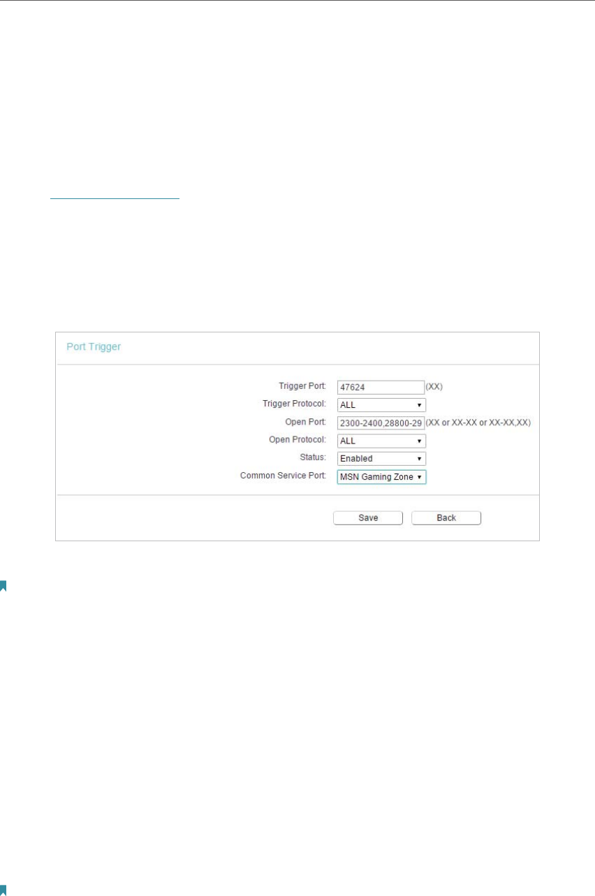
4. 9. 2. Port Triggering
Port triggering can specify a triggering port and its corresponding external ports. When
a host in the local network initiates a connection to the triggering port, all the external
Done!
38
Chapter 4 &RQƮJXUHWKH5RXWHU
ports will be opened for subsequent connections. The router can record the IP address
of the host. When the data from the internet return to the external ports, the router
can forward them to the corresponding host. Port triggering is mainly applied to online
games, VoIPs, video players and common applications including MSN Gaming Zone,
Dialpad, Quick Time 4 players and more.
Follow the steps below to configure the port triggering rules:
1. Visit http://tplinkwifi.net, and log in with the username and password you set for the
router.
2. Go to Forwarding > Port Triggering.
3. Click Add New. Select the desired application from the Common Applications list. The
trigger port amd incoming ports will be automatically filled in. The following picture
takes application MSN Gaming Zone as an example.
4. Leave the status as Enabled and click Save.
Note:
• You can add multiple port triggering rules as needed.
• The triggering ports can not be overlapped.
• If the application you need is not listed in the Common Applications list, please enter the parameters
manually. You should verify the incoming ports the application uses first and enter them in Open Port
field. You can input at most 5 groups of ports (or port sections). Every group of ports must be set apart
with “,”. For example, 2000-2038, 2050-2051, 2085, 3010-3030.
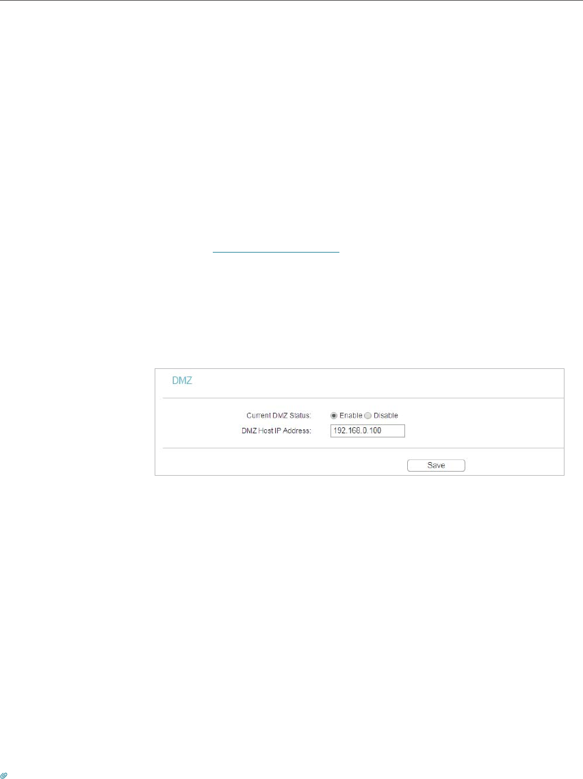
4. 9. 3. DMZ
When a PC is set to be a DMZ (Demilitarized Zone) host in the local network, it is totally
exposed to the internet, which can realize the unlimited bidirectional communication
between internal hosts and external hosts. The DMZ host becomes a virtual server with
all ports opened. When you are not clear about which ports to open in some special
applications, such as IP camera and database software, you can set the PC to be a DMZ
host.
Note:
DMZ is more applicable in the situation that users are not clear about which ports to open. When it is enabled, the DMZ
host is totally exposed to the internet, which may bring some potential safety hazards. If DMZ is not in use, please disable
it in time.
39
Chapter 4 &RQƮJXUHWKH5RXWHU
Make the home PC join the internet online game without port
restriction.
For example, due to some port restriction, when playing the
online games, you can log in normally but cannot join a team
with other players. To solve this problem, set your PC as a DMZ
host with all ports opened.
1. Assign a static IP address to your PC, for example
192.168.0.100.
2. Visit http://tplinkwifi.net, and log in with the username and
password you set for the router.
3. Go to Forwarding > DMZ.
4. Select Enable and enter the IP address 192.168.0.100 in the
DMZ Host IP Address filed.
5. Click Save.
You’ve set your PC to a DMZ host and now you can make a team
to game with other players.
4. 9. 4. UPnP
The UPnP (Universal Plug and Play) protocol allows the applications or host devices
to automatically find the front-end NAT device and send request to it to open the
corresponding ports. With UPnP enabled, the applications or host devices on the
local network and the internet can freely communicate with each other realizing the
seamless connection of the network. You may need to enable the UPnP if you want
to use applications for multiplayer gaming, peer-to-peer connections, real-time
communication (such as VoIP or telephone conference) or remote assistance, etc.
Tips:
• UPnP is enabled by default in this router.
• Only the application supporting UPnP protocol can use this feature.
• UPnP feature needs the support of operating system (e.g. Windows Vista/ Windows 7/ Windows 8, etc.
Some of operating system need to install the UPnP components).
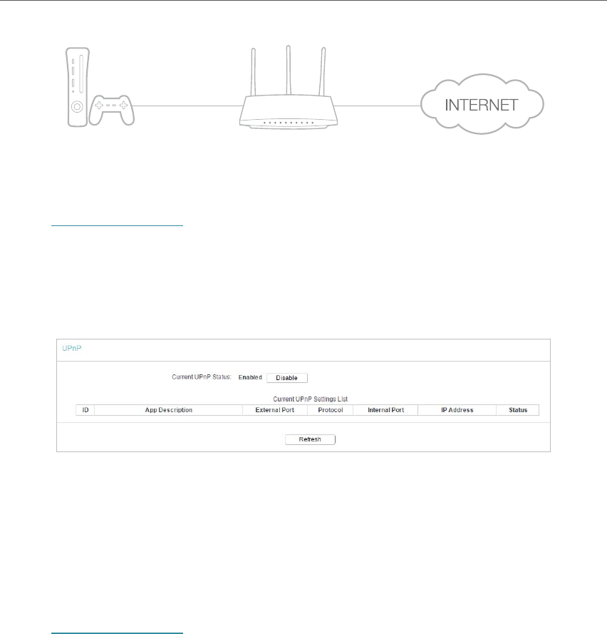
For example, when you connect your Xbox to the router which is connected to the internet
to play online games, UPnP will send request to the router to open the corresponding
ports allowing the following data penetrating the NAT to transmit. Therefore, you can
play Xbox online games without a hitch.
I want to:
How
can I do
that?
Done!
40
Chapter 4 &RQƮJXUHWKH5RXWHU
RouterXbox
LAN WAN
If necessary, you can follow the steps to change the status of UPnP.
1. Visit http://tplinkwifi.net, and log in with the username and password you set for the
router.
2. Go to Forwarding > UPnP.
3. Click Disable or Enable according to your needs.
4. 10. Security
This function allows you to protect your home network from cyber attacks and
unauthorized users by implementing these network security functions.
4. 10. 1. Basic Security
1. Visit http://tplinkwifi.net, and log in with the username and password you set for the
router.
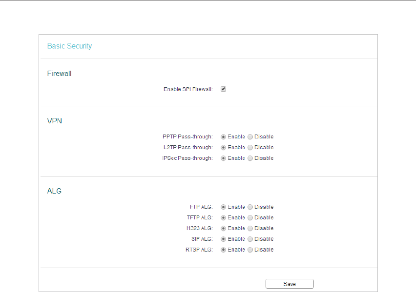
2. Go to Security > Basic Security, and you can enable or disable the security functions.
41
Chapter 4 &RQƮJXUHWKH5RXWHU
• Firewall - A firewall protects your network from internet attacks.
• Enable SPI Firewall - SPI (Stateful Packet Inspection, also known as dynamic
packet filtering) helps to prevent cyber attacks by tracking more state per
session. It validates that the traffic passing through the session conforms to
the protocol. SPI Firewall is enabled by default.
• VPN - VPN Passthrough must be enabled if you want to allow VPN tunnels using IPSec,
PPTP or L2TP protocols to pass through the router’s firewall.
• PPTP Passthrough - Point-to-Point Tunneling Protocol (PPTP) allows the Point-
to-Point Protocol (PPP) to be tunneled through an IP network. If you want to allow
PPTP tunnels to pass through the router, you can keep the default (Enabled).
• L2TP Passthrough - Layer 2 Tunneling Protocol (L2TP) is the method used
to enable Point-to-Point sessions via the internet on the Layer 2 level. If you
want to allow L2TP tunnels to pass through the router, you can keep the default
(Enabled).
• IPSec Passthrough - Internet Protocol Security (IPSec) is a suite of protocols for
ensuring private, secure communications over Internet Protocol (IP) networks,
through the use of cryptographic security services. If you want to allow IPSec
tunnels to pass through the router, you can keep the default (Enabled).
• ALG - It is recommended to enable Application Layer Gateway (ALG) because ALG
allows customized Network Address Translation (NAT) traversal filters to be plugged
into the gateway to support address and port translation for certain application layer
“control/data” protocols such as FTP, TFTP, H323 etc.
42
Chapter 4 &RQƮJXUHWKH5RXWHU
• FTP ALG - To allow FTP clients and servers to transfer data across NAT, keep
the default Enable.
• TFTP ALG - To allow TFTP clients and servers to transfer data across NAT, keep
the default Enable.
• H323 ALG - To allow Microsoft NetMeeting clients to communicate across NAT,
keep the default Enable.
• SIP ALG - To allow some multimedia clients to communicate across NAT, click
Enable.
• RTSP ALG - To allow some media player clients to communicate with some
streaming media servers across NAT, click Enable.
3. Click Save.
4. 10. 2. Advanced Security
1. Visit http://tplinkwifi.net, and log in with the username and password you set for the
router.
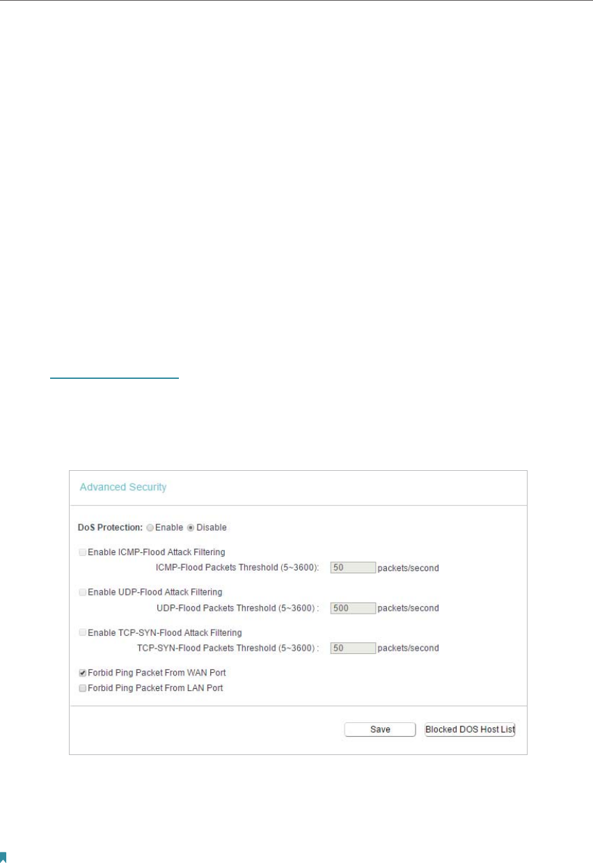
2. Go to Security > Advanced Security, and you can protect the router from being
attacked by ICMP-Flood, UDP Flood and TCP-SYN Flood.
• DoS Protection - Denial of Service protection. Select Enable or Disable to enable or
disable the DoS protection function. Only when it is enabled, will the flood filters be
enabled.
Note:
Dos Protection will take effect only when the Statistics in System Tool > Statistics is enabled.
• Enable ICMP-FLOOD Attack Filtering -Check the box to enable or disable this function.

43
Chapter 4 &RQƮJXUHWKH5RXWHU
• ICMP-FLOOD Packets Threshold (5~3600) - The default value is 50. Enter a value
between 5 ~ 3600. When the number of the current ICMP-FLOOD packets is beyond
the set value, the router will startup the blocking function immediately.
• Enable UDP-FLOOD Filtering - Check the box to enable or disable this function.
• UDP-FLOOD Packets Threshold (5~3600) - The default value is 500. Enter a value
between 5 ~ 3600. When the number of the current UPD-FLOOD packets is beyond
the set value, the router will startup the blocking function immediately.
• Enable TCP-SYN-FLOOD Attack Filtering -Check the box to enable or disable this
function.
• TCP-SYN-FLOOD Packets Threshold (5~3600) - The default value is 50. Enter a value
between 5 ~ 3600. When the number of the current TCP-SYN-FLOOD packets is
beyond the set value, the router will startup the blocking function immediately.
• Forbid Ping Packet From WAN Port - The default setting is enable. If disabled, the ping
packet from the internet can access the router.
• Forbid Ping Packet From LAN Port - The default setting is disabled. If enabled, the
ping packet from LAN cannot access the router. This function can be used to defend
against some viruses.
3. Click Save.
4. Click Blocked DoS Host List to display the DoS host table by blocking.
4. 11. Parental Controls
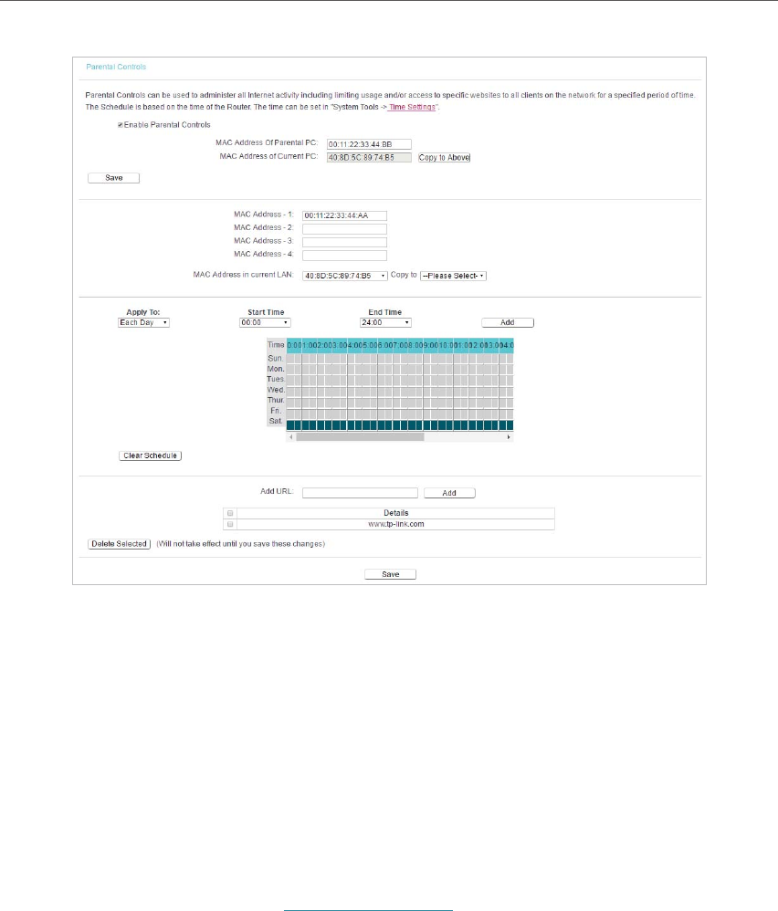
Parental Controls allows you to block inappropriate and malicious websites, and control
access to specific websites at specific time for your children’s devices.
For example, you want the children’s PC with the MAC address 00-11-22-33-44-AA can
access www.tp-link.com on Saturday only while the parent PC with the MAC address
00-11-22-33-44-BB is without any restriction.
1. Visit http://tplinkwifi.net, and log in with the username and password you set for the
router.
2. Go to Parental Controls.
3. Check the Enable Parental Controls box and enter the MAC address 00:11:22:33:44:BB
in the MAC Address of Parental PC field.
4. Enter 00:11:22:33:44:AA in the MAC Address 1 field.
5. Create a new schedule with Day is Sat and Time is all day-24 hours. Click Add
6. Enter www.tp-link.com in the Add URL field. Click Add.
7. Click Save.
Then you will see the page as shown in figure below.
44
Chapter 4 &RQƮJXUHWKH5RXWHU
4. 12. Access Control
Access Control is used to deny or allow specific client devices to access your network
with access time and content restrictions.
Deny or allow specific client devices to access my network with
access tiem and content restrictions.
For example, If you want to restrict the internet activities of host
with MAC address 00-11-22-33-44-AA on the LAN to access
www.tp-link.com only, please follow the steps below:
1. Visit http://tplinkwifi.net, and log in with the username and
password you set for the router.
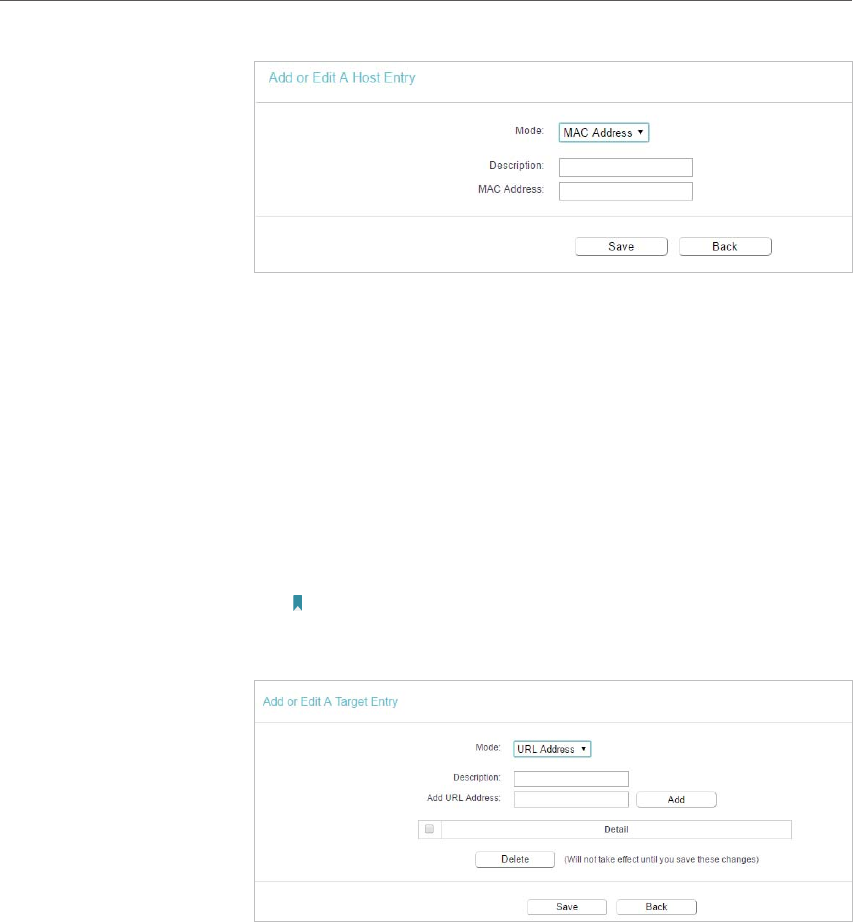
2. Go to Access Control > Host and configure the host settings:
1 ) Click Add New.
2 ) Select MAC Address as the mode type. Create a unique
description (e.g. host_1) for the host in the Description
field and enter 00-11-22-33-44-AA in the MAC Address
filed.
I want to:
How
can I do
that?
45
Chapter 4 &RQƮJXUHWKH5RXWHU
3 ) Click Save.
3. Go to Access Control > Target and configure the target
settings:
1 ) Click Add New.
2 ) Select URL Address as the mode type. Create a unique
description (e.g. target_1) for the target in the Target
Description field and enter the domain name, either the
full name or the keywords (for example TP-Link) in the
Add URL Address field.
Note:
Any URL address with keywords in it (e.g. www.tp-link.com) will be
blocked or allowed.
3 ) Click Save.
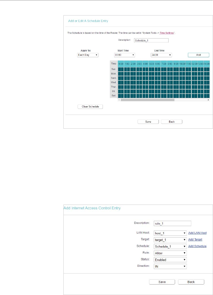
4. Go to Access Control > Schedule and configure the schedule
settings:
1 ) Click Add New.
2 ) Create a unique description (e.g. schedule_1) for the
schedule in the Schedule Description field and set the
day(s) and time period.
46
Chapter 4 &RQƮJXUHWKH5RXWHU
3 ) Click Save.
5. Go to Access Control > Rule and add a new access control
rule.
1 ) Click Add New.
2 ) Give a name for the rule in the Description field. Select
host_1 from the LAN host drop-down list; select target_1
from the target drop-down list; select schedule_1 from
the schedule drop-down list.
3 ) Leave the status as Enabled as click Save.
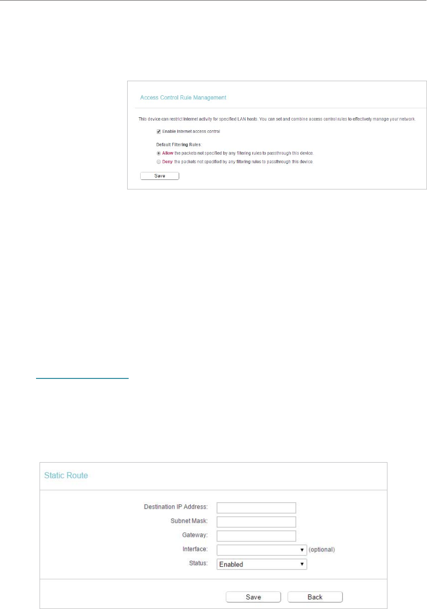
6. Select Enable Internet Access Control to enable Access
Control function.
47
Chapter 4 &RQƮJXUHWKH5RXWHU
7. Select Allow the packets specified by any enabled access
control policy to pass through the Router as the default filter
policy and click Save.
Now only the specific host(s) can visit the target(s) within the
scheduled time period.
4. 13. Advanced Routing
Static Routing is a form of routing that is configured manually by a network administrator
or a user by adding entries into a routing table. The manually-configured routing
information guides the router in forwarding data packets to the specific destination.
4. 13. 1. Static Route List
1. Visit http://tplinkwifi.net, and log in with the username and password you set for the
router.
2. Go to Advanced Routing > Static Route List.
¾To add static routing entries:
1. Click Add New.
2. Enter the following information.
• Destination IP Address - The Destination Network is the address of the network
or host that you want to assign to a static route.
Done!
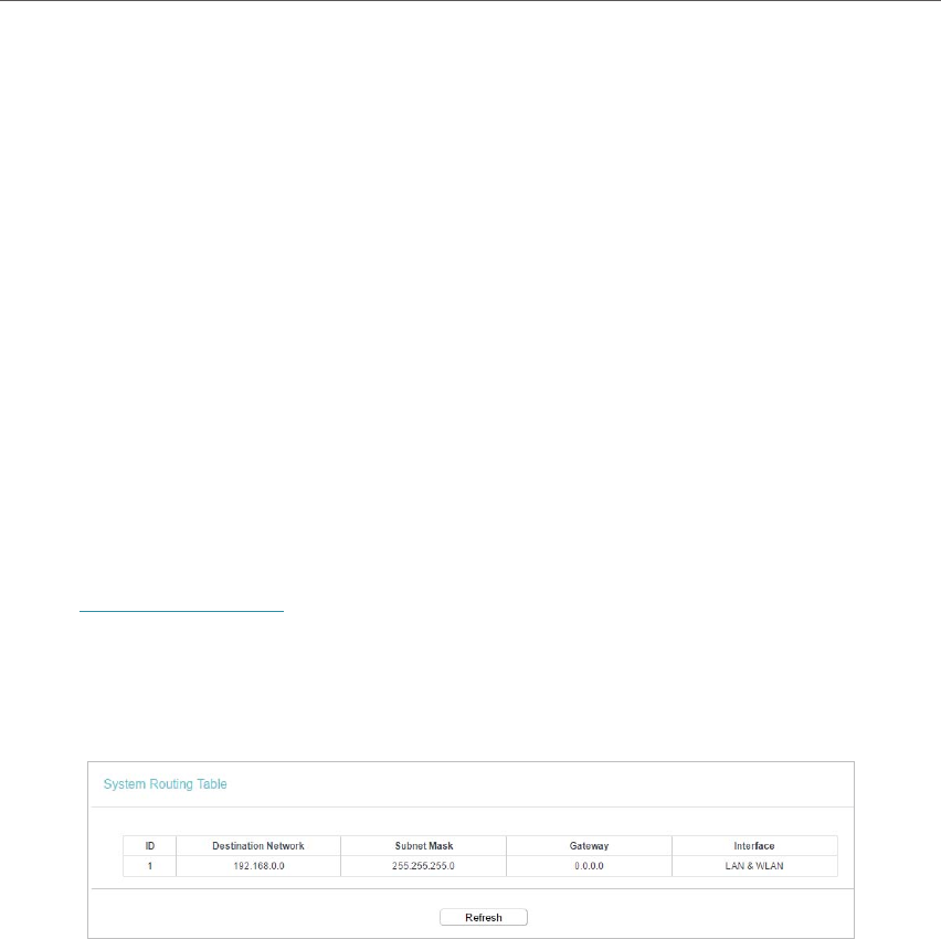
48
Chapter 4 &RQƮJXUHWKH5RXWHU
• Subnet Mask - The Subnet Mask determines which portion of an IP address is
the network portion, and which portion is the host portion.
• Gateway - This is the IP address of the default gateway device that allows the
contact between the router and the network or host.
3. Select Enabled or Disabled for this entry on the Status drop-down list.
4. Click Save.
You can also do the following operations to modify the current settings.
• Click
Delete to delete the entry.
• Click
Enable Selected to enable all the entries.
• Click
Disable Selected to disable all the entries.
• Click
Delete Selected to delete all the entries.
4. 13. 2. System Routing Table
1. Visit http://tplinkwifi.net, and log in with the username and password you set for the
router.
2. Go to Advanced Routing > System Routing Table, and you can view all the valid route
entries in use.
• Destination Network - The Destination Network is the address of the network or host
to which the static route is assigned.
• Subnet Mask - The Subnet Mask determines which portion of an IP address is the
network portion, and which portion is the host portion.
• Gateway - This is the IP address of the gateway device that allows for contact between
the Router and the network or host.
• Interface - This interface tells you whether the Destination IP Address is on the LAN &
WLAN (internal wired and wireless networks), or the WAN (Internet).
• Click
Refresh to refresh the data displayed.
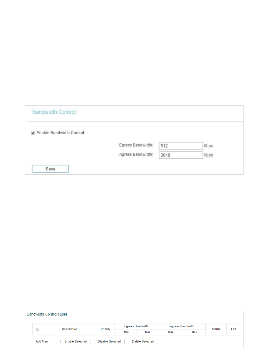
49
Chapter 4 &RQƮJXUHWKH5RXWHU
4. 14. Bandwidth Control
4. 14. 1. Control Settings
1. Visit http://tplinkwifi.net, and log in with the username and password you set for the
router.
2. Go to Bandwidth Control.
3. Configure the bandwidth as needed and click Save.
The values you configure for the Egress Bandwidth and Ingress Bandwidth should be
less than 100,000Kbps. For optimal control of the bandwidth, please select the right
Line Type and consult your ISP for the total egress and ingress bandwidth.
• Enable Bandwidth Control - Check this box so that the Bandwidth Control settings
can take effect.
• Egress Bandwidth - The upload speed through the WAN port.
• Ingress Bandwidth - The download speed through the WAN port.
4. 14. 2. Rule List
1. Visit http://tplinkwifi.net, and log in with the username and password you set for the
router.
2. Go to Bandwidth Control and you can view and configure the Bandwidth Control rules.
• Description - This is the information about the rules such as address range.
• Egress Bandwidth - This field displays the max and min upload bandwidth through the
WAN port. The default is 0.
• Ingress Bandwidth - This field displays the max and min download bandwidth through
the WAN port. The default is 0.
• Status - This field displays the status of the rule.
• Modify - Click Modify/Delete to edit/delete the rule.
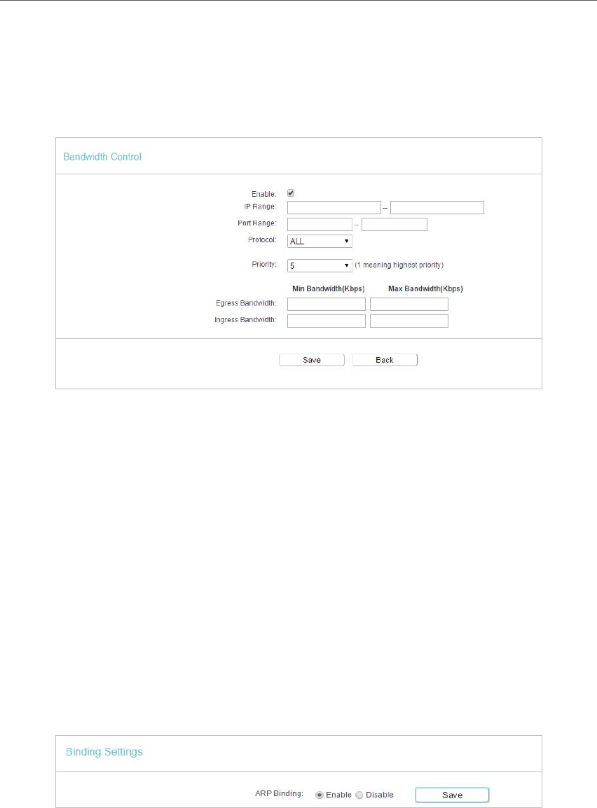
50
Chapter 4 &RQƮJXUHWKH5RXWHU
¾To add a Bandwidth control rule:
1. Click Add New.
2. Enter the information as the figure shown below.
3. Click Save.
4. 15. IP&MAC Binding
IP & MAC Binding, namely, ARP (Address Resolution Protocol) Binding, is used to bind
a network device’s IP address to its MAC address. This will prevent ARP spoofing and
other ARP attacks by denying network access to a device with a matching IP address in
the ARP list, but with an unrecognized MAC address.
4. 15. 1. Binding Settings
1. Visit http://tplinkwifi.net, and log in with the username and password you set for the
router.
2. Go to IP & MAC Binding > Binding Settings.
3. Select Enable for ARP Binding.
4. Click Save.
¾To add IP & MAC Binding entries:
1. Click Add New.
2. Select the Bind checkbox.
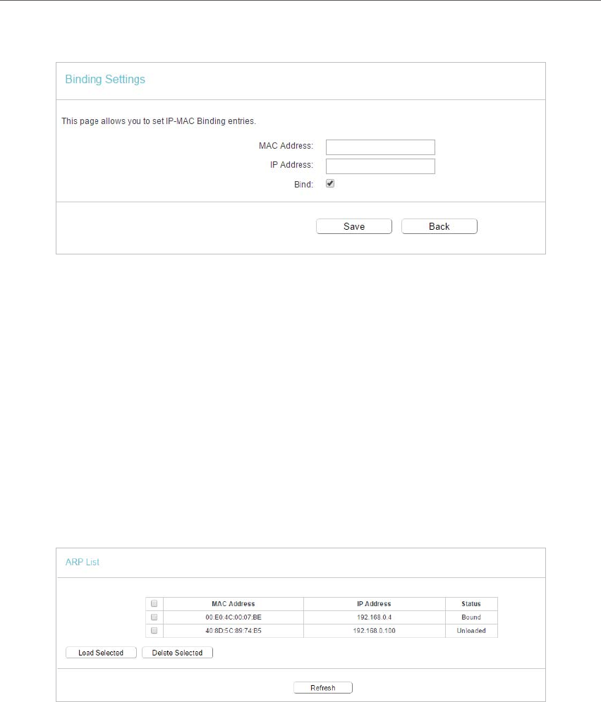
51
Chapter 4 &RQƮJXUHWKH5RXWHU
3. Enter the MAC address and IP address.
4. Click Save.
¾To modify or delete an existing entry:
1. Select the desired entry in the table.
2. Click Edit or Delete Selected.
4. 15. 2. ARP List
To manage a device, you can observe the device on the LAN by checking its MAC
address and IP address on the ARP list, and you can also configure the items. This page
displays the ARP list which shows all the existing IP & MAC Binding entries.
• MAC Address - The MAC address of the listed computer on the LAN.
• IP Address - The assigned IP address of the listed computer on the LAN.
• Status - Indicates whether or not the MAC and IP addresses are bound.
• Configure - Load or delete an item.
• Load - Load the item to the IP & MAC Binding list.
• Delete - Delete the item.
• Click the
Load Selected button to load the selected items to the IP & MAC Binding list.
• Click the Delete Selected button to delete the selected items to the IP & MAC Binding
list.
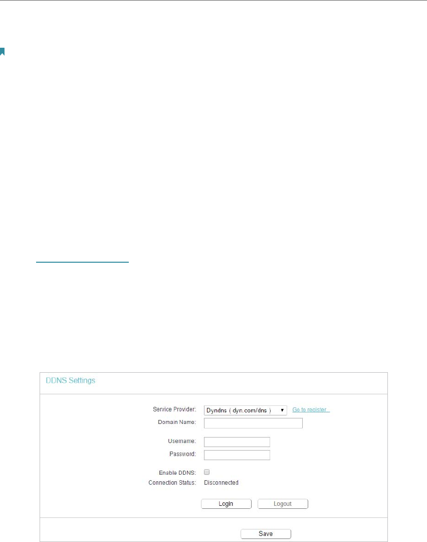
52
Chapter 4 &RQƮJXUHWKH5RXWHU
• Click the Refresh button to refresh all items.
Note:
An item can not be loaded to the IP & MAC Binding list if the IP address of the item has been loaded before. Error warning
will prompt as well.
4. 16. Dynamic DNS
The router offers the DDNS (Dynamic Domain Name System) feature, which allows the
hosting of a website, FTP server, or e-mail server with a fixed domain name (named by
yourself) and a dynamic IP address. Thus your friends can connect to your server by
entering your domain name no matter what your IP address is. Before using this feature,
you need to sign up for DDNS service providers such as www.comexe.cn,
www.dyndns.org, or www.noip.com. The Dynamic DNS client service provider will give
you a password or key.
1. Visit http://tplinkwifi.net, and log in with the username and password you set for the
router.
2. Go to Dynamic DNS.
Dyndns DDNS
If the dynamic DNS Service Provider you select is www.dyn.com, the following page will
appear.
To set up for DDNS, follow these instructions:
1. Enter the Domain Name you received from dynamic DNS service provider here.
2. Enter the Username for your DDNS account.
3. Enter the Password for your DDNS account.
4. Click Login.
5. Click Save.
• Connection Status - The status of the DDNS service connection is displayed here.
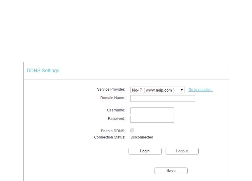
53
Chapter 4 &RQƮJXUHWKH5RXWHU
• Logout - Click Logout to log out of the DDNS service.
No-ip DDNS
If the dynamic DNS Service Provider you select is www.noip.com, the following page
will appear.
To set up for DDNS, follow these instructions:
1. Enter the Domain Name you received from dynamic DNS service provider.
2. Enter the Username for your DDNS account.
3. Enter the Password for your DDNS account.
4. Click Login.
5. Click Save.
• Connection Status - The status of the DDNS service connection is displayed here.
• Logout - Click Logout to log out of the DDNS service.
Comexe DDNS
If the dynamic DNS Service Provider you select is www.comexe.cn, the following page
will appear.
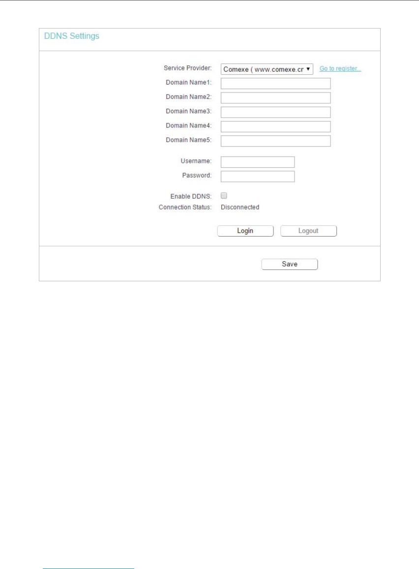
54
Chapter 4 &RQƮJXUHWKH5RXWHU
To set up for DDNS, follow these instructions:
1. Enter the Domain Name received from your dynamic DNS service provider.
2. Enter the Username for your DDNS account.
3. Enter the Password for your DDNS account.
4. Click Login.
5. Click Save.
• Connection Status - The status of the DDNS service connection is displayed here.
• Logout - Click Logout to log out of the DDNS service.
4. 17. IPv6
This function allows you to enable IPv6 function and set up the parameters of the
router’s Wide Area Network (WAN) and Local Area Network (LAN).
4. 17. 1. IPv6 Status
1. Visit http://tplinkwifi.net, and log in with the username and password you set for the
router.
2. Go to IPv6 > IPv6 Status, and you can view the current IPv6 status information of
the router.
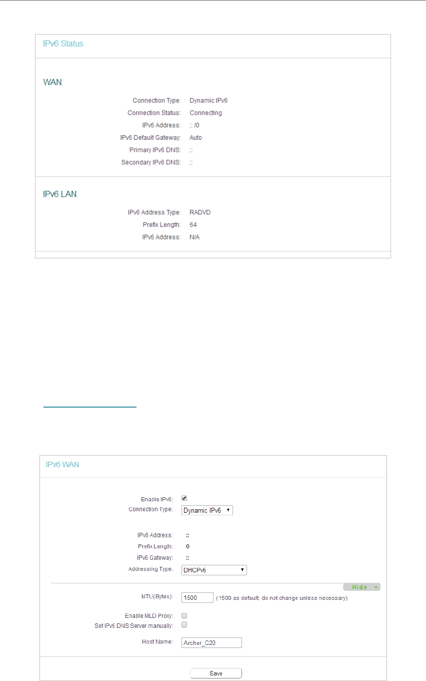
55
Chapter 4 &RQƮJXUHWKH5RXWHU
• WAN - This section shows the current IPv6 information of the router’s WAN port,
including Connection Type, IPv6 Address information, IPv6 Default Gateway, Primary
IPv6 DNS and Secondary IPv6 DNS.
• IPv6 LAN - This section shows the current IPv6 information of the router’s LAN port,
including IPv6 Address Assign Type, IPv6 Address and Link-local Address.
4. 17. 2. IPv6 WAN
1. Visit http://tplinkwifi.net, and log in with the username and password you set for the
router.
2. Go to IPv6 > IPv6 WAN.
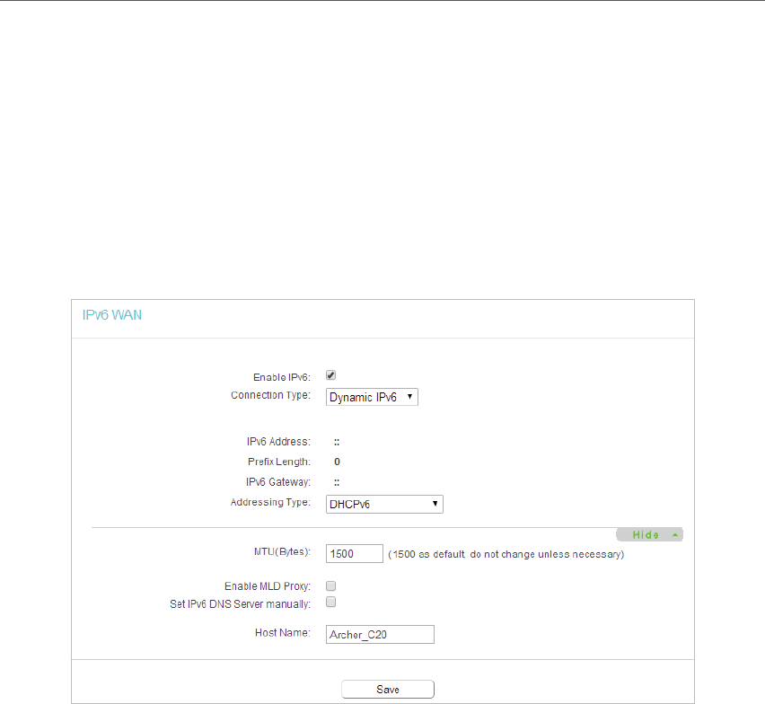
56
Chapter 4 &RQƮJXUHWKH5RXWHU
3. Select the WAN Connection Type according to your ISP network topolopy:
• Dynamic IPv6 - Connections which use dynamic IPv6 address assignment.
• Static IPv6 - Connections which use static IPv6 address assignment.
• PPPoEv6 - Connections which use PPPoEV6 that requires a username and
password.
• Tunnel 6to4 - Connections which use 6to4 address assignment.
Dynamic IPv6
• IPv6 Address - The IPv6 address assigned by your ISP dynamically.
• Prefix Length - The length of IPv6 address prefix.
• IPv6 Gateway - Enter the default gateway provided by your ISP.
• Addressing Type - There are two types of assignation for IPv6 address:
SLAAC (Stateless address auto-configuration) and DHCPv6 (Dynamic Host
Configuration Protocol for IPv6) Server.
• MTU(Bytes) - The normal MTU (Maximum Transmission Unit) value for most
Ethernet networks is 1500 Bytes. For some ISPs, you may need to modify the
MTU. But this is rarely required, and should not be done unless you are sure it is
necessary for your ISP connection.
If your ISP gives you one or two DNS IPv6 addresses, select Set IPv6 DNS Server
manually and enter the IPv6 DNS Server and Secondary IPv6 DNS Server into the
correct fields. Otherwise, the DNS servers will be assigned from ISP dynamically.
• Enable MLD Proxy - Enable the Multicast Listener Discovery (MLD) Proxy
function if you need.
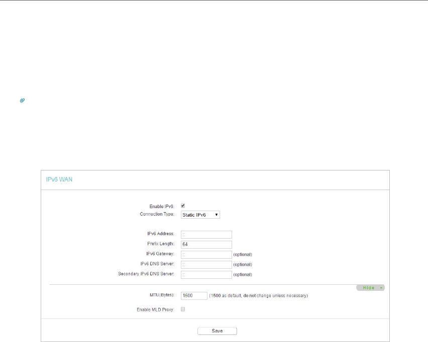
57
Chapter 4 &RQƮJXUHWKH5RXWHU
• Set IPv6 DNS Server manually - Enter the DNS IPv6 address provided by your
ISP.
• Secondary IPv6 DNS Server - Enter another DNS IPv6 address provided by
your ISP.
Tips:
If you get Address not found error when you access a website, it is likely that your DNS servers are set up improperly.
You should contact your ISP to get DNS server addresses.
Static IPv6
• IPv6 Address - Enter the IPv6 address provided by your ISP.
• Prefix Length - The length of IPv6 address prefix.
• IPv6 Gateway - Enter the default gateway provided by your ISP.
• IPv6 DNS Server- Enter the DNS IPv6 address provided by your ISP.
• Secondary IPv6 DNS Server - Enter another DNS IPv6 address provided by
your ISP.
• MTU(Bytes) - The normal MTU (Maximum Transmission Unit) value for most
Ethernet networks is 1500 Bytes. For some ISPs, you may need to modify the
MTU. But this is rarely required, and should not be done unless you are sure it is
necessary for your ISP connection.
• Enable MLD Proxy - Enable the Multicast Listener Discovery (MLD) Proxy
function if you need.
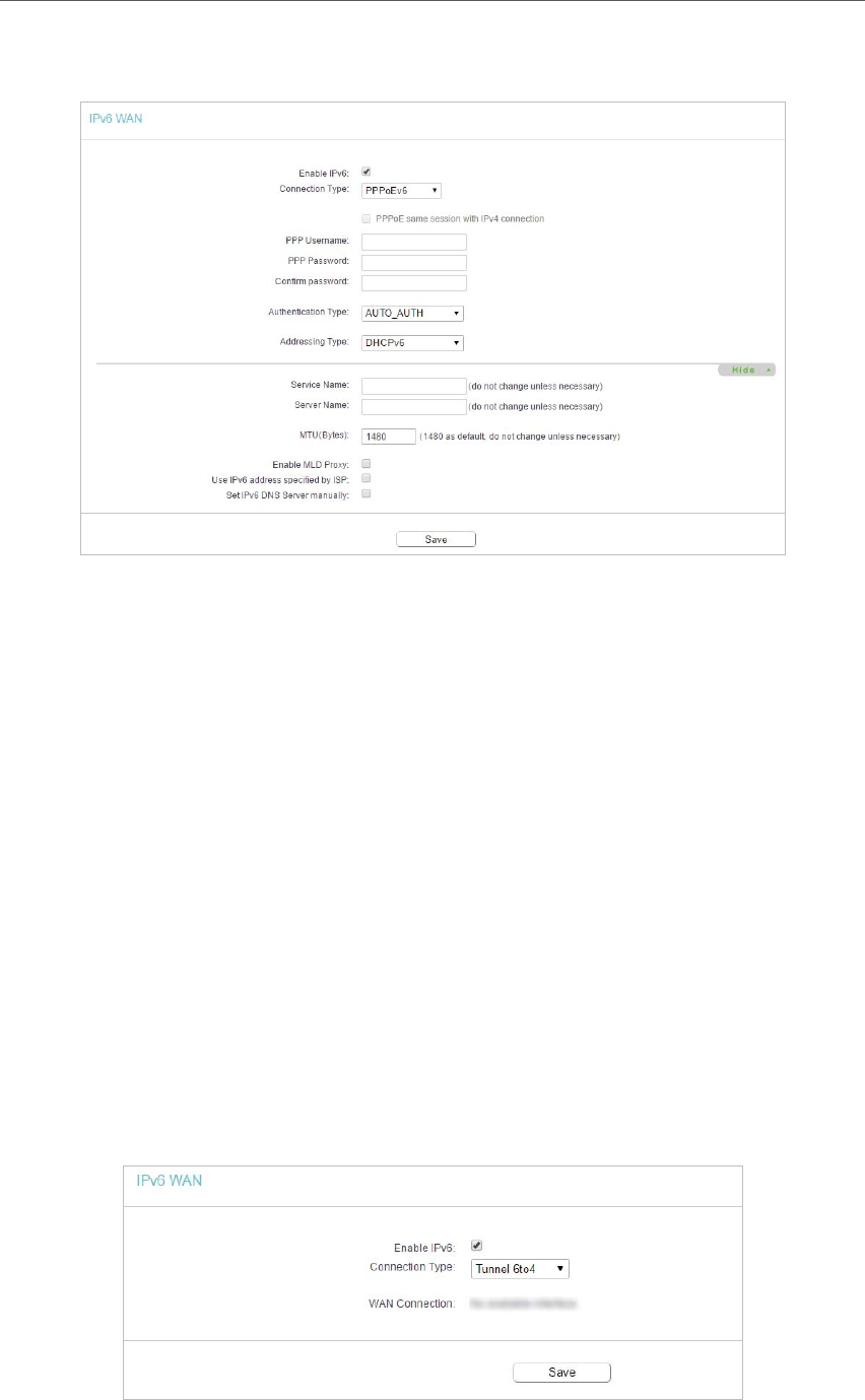
58
Chapter 4 &RQƮJXUHWKH5RXWHU
PPPoEv6
• PPP Username/Password - Enter the User Name and Password provided by
your ISP. These fields are case-sensitive.
• Authentication Type – Choose one authentication type from AUTO-AUTH, PAP,
CHAP and MS-CHAP.
• Addressing Type - There are two types of assignation for IPv6 address:
SLAAC (Stateless address auto-configuration) and DHCPv6 (Dynamic Host
Configuration Protocol for IPv6) Server.
• MTU(Bytes) - The normal MTU (Maximum Transmission Unit) value for most
Ethernet networks is 1480 Bytes. It is not recommended that you change the
default MTU size unless required by your ISP.
• Enable MLD Proxy - Enable the Multicast Listener Discovery (MLD) Proxy
function if you need.
• Use IPv6 address specified by ISP - Input a static IPv6 address from the ISP.
• Set IPv6 DNS Server manually - Enter the IP address of the IPv6 DNS server
and secondary IPv6 DNS server.
Tunnel 6to4
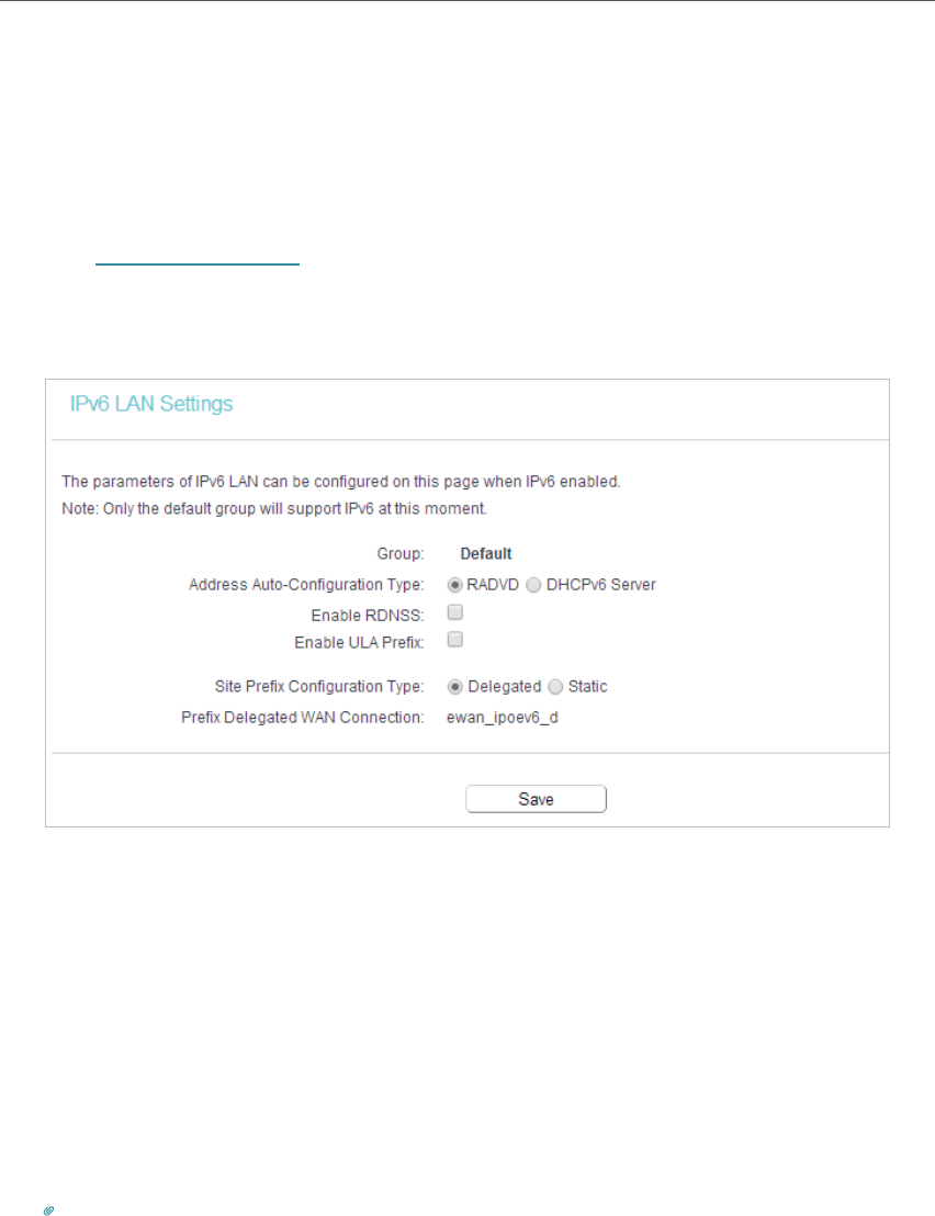
59
Chapter 4 &RQƮJXUHWKH5RXWHU
• WAN Connection - Display the available WAN connection.
4. Click Save.
4. 17. 3. IPv6 LAN
1. Visit http://tplinkwifi.net, and log in with the username and password you set for the
router.
2. Go to IPv6 > IPv6 LAN.
3. Select the Address Autoconfiguration Type which determines the way how the
router assigns IPv6 address for PCs on the LAN:
• Address Autoconfiguration Type - RADAD (Router Advertisement Daemon) and
DHCPv6 (Dynamic Host Configuration Protocol for IPv6) Server.
• Site Prefix Configuration Type - The type of IPv6 address prefix.
• Delegated - Get the IPv6 address prefix from the ISP automatically, and the
device will delegate it to the LAN.
• Static - Configure the Site Prefix and Site Prefix Length manually. Please
contact your ISP to get more information before you configure them.
Tips: If your IPv6 wan connection type is “Tunnel 6to4”, the Site Prefix Configuration Type should be “Static” to
make sure “Tunnel 6to4” works properly.
4. Click Save.
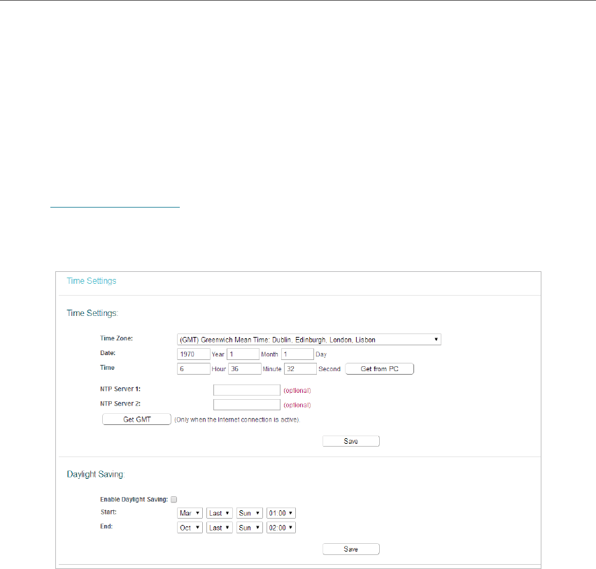
60
Chapter 4 &RQƮJXUHWKH5RXWHU
4. 18. System Tools
4. 18. 1. Time Settings
This page allows you to set the time manually or to configure automatic time
synchronization. The Router can automatically update the time from an NTP server via
the internet.
1. Visit http://tplinkwifi.net, and log in with the username and password you set for the
router.
2. Go to System Tools > Time Settings.
¾To set time manually:
1. Select your local time zone.
2. Enter the Date in Month/Day/Year format.
3. Enter the Time in Hour/Minute/Second format.
4. Click Save.
¾To set time automatically:
5. Select your local time zone.
6. Enter the address or domain of the NTP Server 1 or NTP Server 2.
7. Click Get GMT to get time from the internet if you have connected to the internet.
¾To set Daylight Saving:
1. Select Enable DaylightSaving.
2. Select the start time from the drop-down list in the Start field.
3. Select the end time from the drop-down list in the End field.
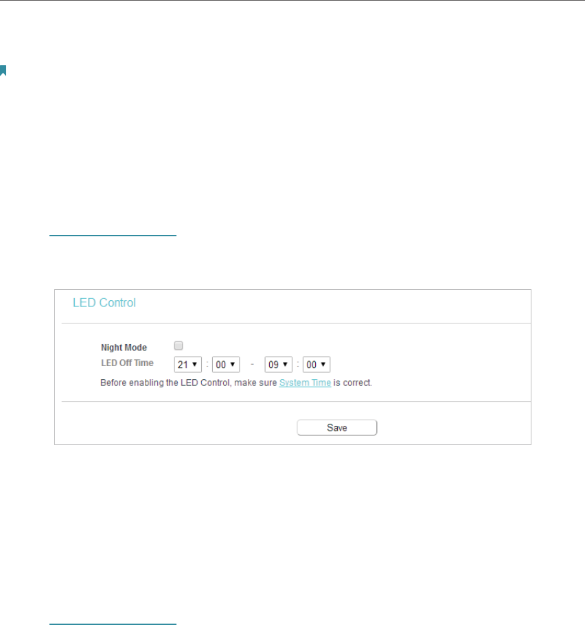
61
Chapter 4 &RQƮJXUHWKH5RXWHU
4. Click Save.
Note:
This setting will be used for some time-based functions such as firewall. You must specify your time zone once you log
in to the router successfully; otherwise, time-based functions will not take effect.
4. 18. 2. LED Control
The LED Control allows you to turn on or off the LEDs on your device according to a
specific time schedule.
1. Visit http://tplinkwifi.net, and log in with the username and password you set for the
router.
2. Go to System Tools > LED Control.
3. Enable the Night Mode.
4. Set the LED Off Time and click Save.
4. 18. 3. Diagnostic
Diagnostic is used to test the connectivity between the router and the host or other
network devices.
1. Visit http://tplinkwifi.net, and log in with the username and password you set for the
router.
2. Go to System Tools > Diagnostic.

62
Chapter 4 &RQƮJXUHWKH5RXWHU
• Diagnostic Tool - Select one diagnostic tool.
• Ping - This diagnostic tool troubleshoots connectivity, reachability, and name
resolution to a given host or gateway.
• Tracerouter - This diagnostic tool tests the performance of a connection.
Note:
You can use ping/traceroute to test both numeric IP address or domain name. If pinging/tracerouting the IP address is
successful, but pinging/tracerouting the domain name is not, you might have a name resolution problem. In this case,
ensure that the domain name you are specifying can be resolved by using Domain Name System (DNS) queries.
• IP Address/Domain Name - Enter the destination IP address (such as 192.168.0.1) or
Domain name (such as www.tp-link.com).
• Pings Count - The number of Ping packets for a Ping connection.
• Ping Packet Size - The size of Ping packet.
• Ping Timeout - Set the waiting time for the reply of each Ping packet. If there is no
reply in the specified time, the connection is overtime.
• Traceroute Max TTL - The max number of hops for a Traceroute connection.
3. Click Start to check the connectivity of the internet.
4. The Diagnostic Results page displays the diagnosis result. If the result is similar to
the following figure, the connectivity of the internet is fine.
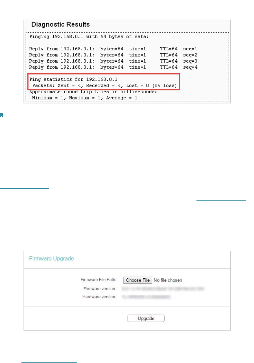
63
Chapter 4 &RQƮJXUHWKH5RXWHU
Note: Only one user can use this tool at one time. Options “Number of Pings”, “Ping Size” and “Ping Timeout” are used
for the Ping function. Option “Tracert Hops” is used for the Tracert function.
4. 18. 4. Firmware Upgrade
TP-Link is dedicated to improving and richening the product features, giving users
a better network experience. We will release the latest firmware at TP-Link official
website. You can download the latest firmware file from the Support page of our website
www.tp-link.com and upgrade the firmware to the latest version.
1. Download the latest firmware file for the router from our website www.tp-link.com.
2. Visit http://tplinkwifi.net, and log in with the username and password you set for the
router.
3. Go to System Tools > Firmware Upgrade.
4. Click Choose File to locate the downloaded firmware file, and click Upgrade.
4. 18. 5. Factory Defaults
1. Visit http://tplinkwifi.net, and log in with the username and password you set for the
router.
2. Go to System Tools > Factory Defaults. Click Restore to reset all settings to the
default values.
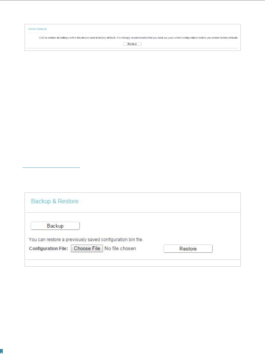
64
Chapter 4 &RQƮJXUHWKH5RXWHU
• The default Username: admin
• The default
Password: admin
• The default
IP Address: 192.168.0.1
• The default
Subnet Mask: 255.255.255.0
4. 18. 6. Backup & Restore
The configuration settings are stored as a configuration file in the router. You can
backup the configuration file in your computer for future use and restore the router to
the previous settings from the backup file when needed.
1. Visit http://tplinkwifi.net, and log in with the username and password you set for the
router.
2. Go to System Tools > Backup & Restore.
¾To backup configuration settings:
Click Backup to save a copy of the current settings in your local computer. A “.bin“ file
of the current settings will be stored in your computer.
¾To restore configuration settings:
1. Click Choose File to locate the backup configuration file stored in your computer, and
click Restore.
2. Wait a few minutes for the restoring and rebooting.
Note:
During the restoring process, do not power off or reset the router.
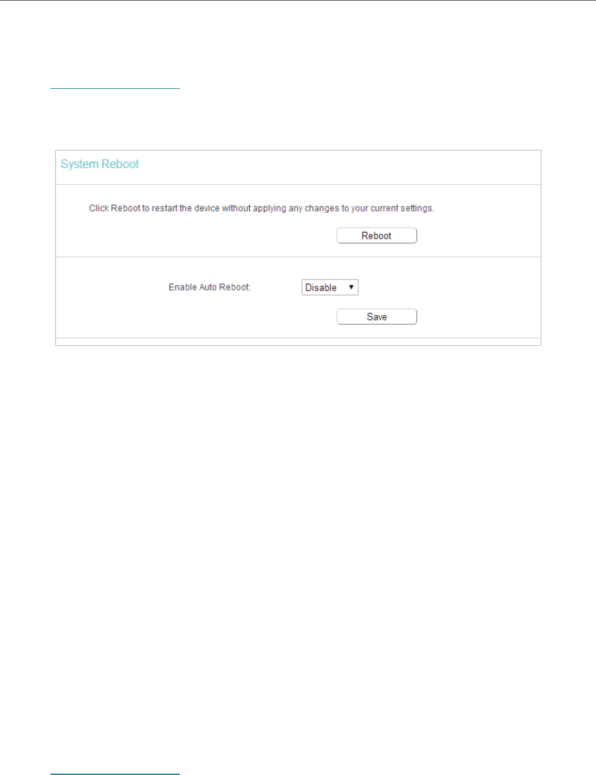
65
Chapter 4 &RQƮJXUHWKH5RXWHU
4. 18. 7. Reboot
1. Visit http://tplinkwifi.net, and log in with the username and password you set for the
router.
2. Go to System Tools > Reboot, and you can restart your router.
3. Enable the auto reboot function as needed.
• Disable - Disable the auto reboot function.
• Timeout - Specify a time period(1-72 hours), then the router will reboot
automatically after every this interval.
• Schedule - The router will reboot automatically according to a specific time
schedule.
Some settings of the router will take effect only after rebooting, including:
• Change the LAN IP Address (system will reboot automatically).
• Change the DHCP Settings.
• Change the Working Modes.
• Change the Web Management Port.
• Upgrade the firmware of the router (system will reboot automatically).
• Restore the router to its factory defaults (system will reboot automatically).
• Update the configuration with the file (system will reboot automatically).
4. 18. 8. Administrator
1. Visit http://tplinkwifi.net, and log in with the username and password you set for the
router.
2. Go to System Tools > Administrator, and you can change the factory default username
and password of the router, and manage your router from a remote location via the
internet.
¾To view and change the account settings:
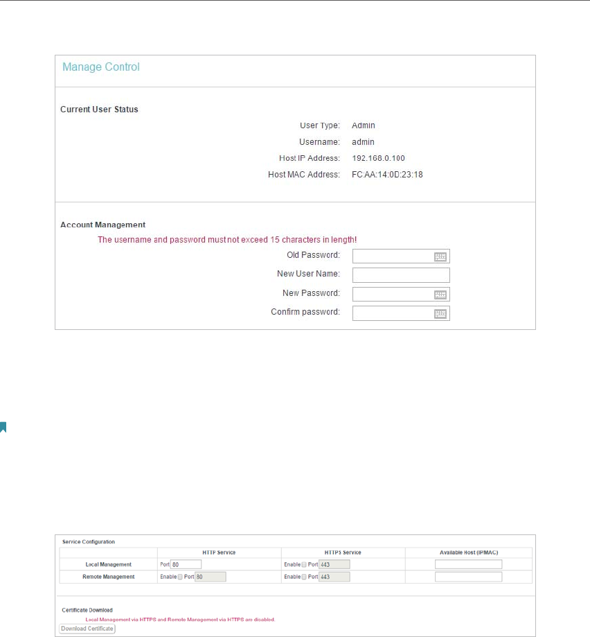
66
Chapter 4 &RQƮJXUHWKH5RXWHU
It is strongly recommended that you change the default username and password of the
router, for all users that try to access the router’s web management or Quick Setup will
be prompted for the router’s username and password.
Note:
The new username and password must not exceed 15 characters and not include any spacing.
¾To manage your Router from a remote location via the internet:
1. Specify the remote management web port number and click Save.
• Web Management Port - The default remote management web port number is
80. For greater security, you can change the remote management web port to
a number between 1024 and 65535 but do not use the number of any common
service port.
• Remote Management IP Address - This is the current address you will use when
accessing your router from the internet. This function is disabled when the IP
address is set to the default value of 0.0.0.0. To enable this function change
0.0.0.0 to a valid IP address. If set to 255.255.255.255, then all the hosts can
access the router from internet.
• Certificate - A file that provides you with authentication information. Download
and install the certificate for Local/Remote Management via HTTPS if you need
it. Once the certificate is installed, warnings will not pop up when you access
the router via HTTPS.
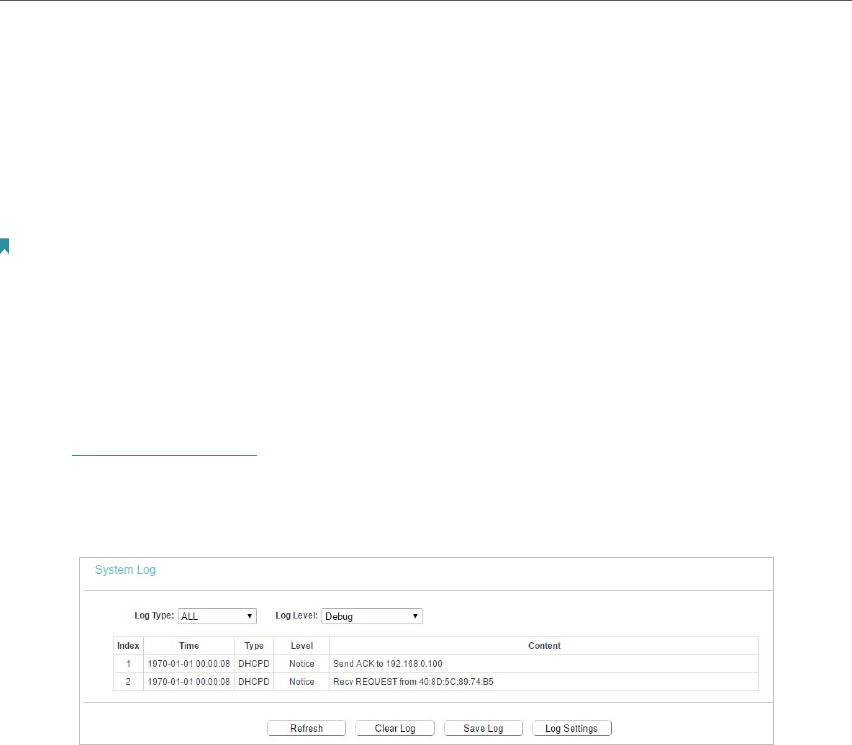
67
Chapter 4 &RQƮJXUHWKH5RXWHU
2. Enter your router’s WAN IP address into your browser’s address bar, followed by a
colon and the custom port number you set in the Web Management Port box. For
example, if your Router’s WAN address is 202.96.12.8 and you use port number 8080,
enter http://202.96.12.8:8080 in your browser.
3. Enter the router’s password to access the web mangement page remotely.
Note:
• Be sure to change the router’s default password to a secure password.
• If the web management port conflicts with the one used for a Virtual Server entry, the entry will be
automatically disabled after the setting is saved.
4. 18. 9. System Log
1. Visit http://tplinkwifi.net, and log in with the username and password you set for the
router.
2. Go to System Tools > System Log, and you can view the logs of the router.
• Loge Type -By selecting the log type, only logs of this type will be shown.
• Log Level - By selecting the log level, only logs of this level will be shown.
• Refresh - Refresh the page to show the latest log list.
• Clear Log - All the logs will be deleted from the router permanently, not just from the
page.
4. 19. Log Out
Click Logout at the bottom of the main menu, and you will log out of the web page and
be directed to the login window.

Chapter 5
Configure the Router in
Access Point Mode
This chapter presents how to configure the various features of the router in Access
Point Mode.
It contains the following sections:
• Status
• Quick Setup
• Operation Mode
• Network
• Dual Band Selection
• Wireless(2.4GHz or 5GHz)
• Guest Network
• DHCP
• System Tools
• Log Out
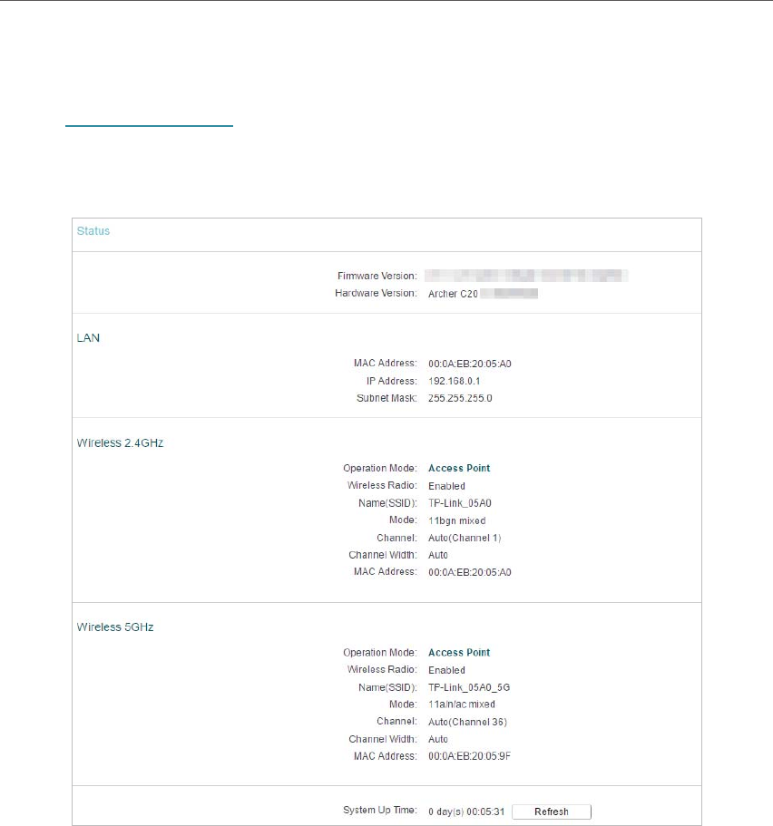
69
Chapter 5 &RQƮJXUHWKH5RXWHULQ$FFHVV3RLQW0RGH
5. 1. Status
1. Visit http://tplinkwifi.net, and log in with the username and password you set for the
router.
2. Go to Status. You can view the current status information of the router.
• Firmware Version - The version information of the router’s firmware.
• Hardware Version - The version information of the router’s hardware.
• LAN - This field displays the current settings of the LAN, and you can configure them
on the Network > LAN page.
• MAC address - The physical address of the router.
• IP address - The LAN IP address of the router.
• Subnet Mask - The subnet mask associated with the LAN IP address.
• Wireless 2.4GHz/5GHz - This field displays the basic information or status of the
wireless function, and you can configure them on the Wireless > Basic Settings page.
• Operation Mode - The current wireless working mode in use.
• Wireless Radio - Indicates whether the wireless radio feature of the Router is
enabled or disabled.
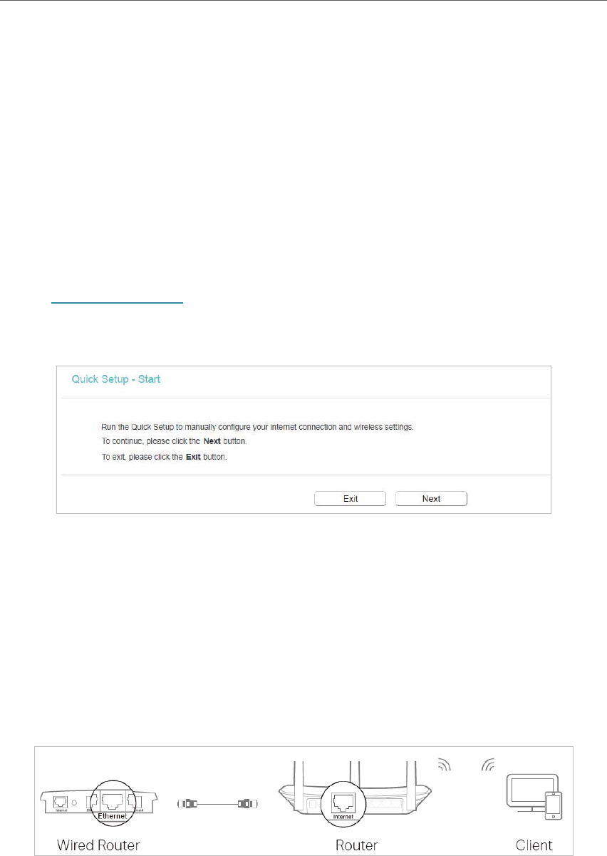
70
Chapter 5 &RQƮJXUHWKH5RXWHULQ$FFHVV3RLQW0RGH
• Name(SSID) - The SSID of the Router.
• Mode - The current wireless mode which the router works on.
• Channel - The current wireless channel in use.
• Channel Width - The current wireless channel width in use.
• MAC Address - The physical address of the router.
• System Up Time - The length of time since the AP was last powered on or reset. Click
Refresh to get the latest status and settings of the AP.
5. 2. Quick Setup
1. Visit http://tplinkwifi.net, and log in with the username and password you set for the
router.
2. Go to Quick Setup.
3. Click Next to start. Then follow the step-by-step instructions to connect your router
to the internet.
5. 3. Operation Mode
The router supports three operation modes: Wireless Router mode, Access Point mode
and Range Extender. In Access Point mode, the device can be connected to a wired
network and transform the wired access into wireless one. If you already have a wired
router, you can use this mode. To switch to Access Point mode:
1. Find the router’s Internet port, and connect it to the Ethernet port (LAN port) of your
existing wired router. Then connect the power adapter and turn on the router.
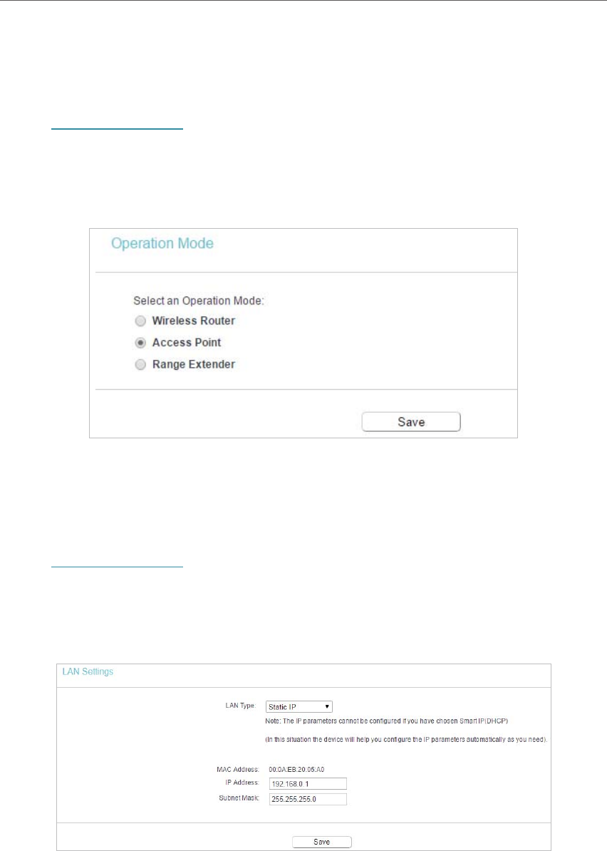
71
Chapter 5 &RQƮJXUHWKH5RXWHULQ$FFHVV3RLQW0RGH
2. Connect your computer to the router via an Ethernet cable or wirelessly by using the
SSID (network name) and Wireless Password printed on the label at the bottom of the
router.
3. Visit http://tplinkwifi.net, and log in with the username and password you set for the
router.
4. Go to Operation Mode.
5. Select the Access Point mode and click Save.
5. 4. Network
5. 4. 1. LAN
1. Visit http://tplinkwifi.net, and log in with the username and password you set for the
router.
2. Go to Network > LAN.
3. Configure the IP parameters of the LAN and click Save.
• LAN Type - Select Smart IP(DHCP) to get IP address from DHCP server, or select
static IP to configure IP address manually.
• MAC Address - The physical address of the LAN ports. The value can not be changed.
• IP Address - Enter the IP address in dotted-decimal notation of your router.
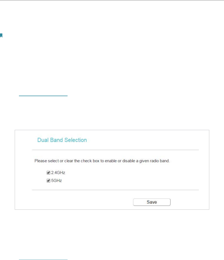
72
Chapter 5 &RQƮJXUHWKH5RXWHULQ$FFHVV3RLQW0RGH
• Subnet Mask - An address code that determines the size of the network. Normally
255.255.255.0 is used as the subnet mask.
Note:
• If you change the IP address, you must use the new IP address to login to the device.
• If you select the type of smart IP(DHCP), the DHCP server in this device will not startup.
• If the new IP address you set is not in the same subnet with the previous one, the IP Address pool in the
DHCP server will be configured automatically.
5. 5. Dual Band Selection
1. Visit http://tplinkwifi.net, and log in with the username and password you set for the
router.
2. Go to Dual Band Selection.
3. Select the working radio band as needed and click Save.
5. 6. Wireless(2.4GHz or 5GHz)
5. 6. 1. Wireless Settings
1. Visit http://tplinkwifi.net, and log in with the username and password you set for the
router.
2. Go to Wireless > Basic Settings.
3. Configure the basic settings for the wireless network and click Save.
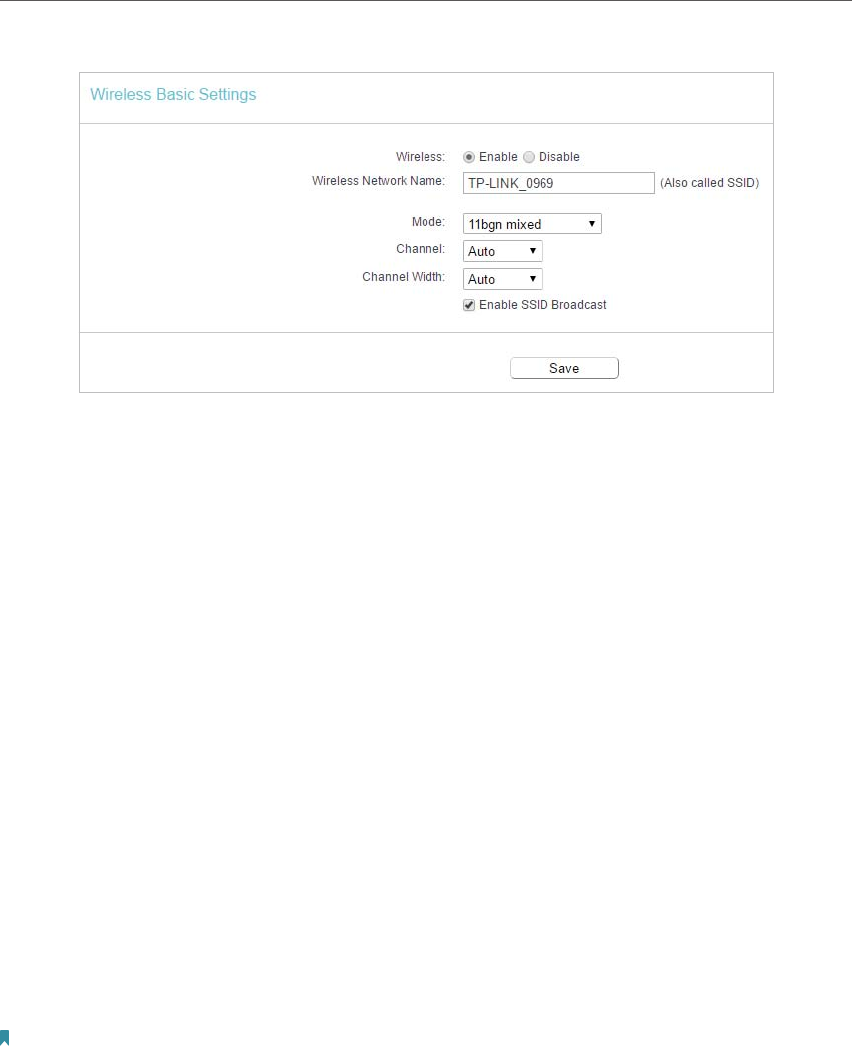
73
Chapter 5 &RQƮJXUHWKH5RXWHULQ$FFHVV3RLQW0RGH
• Wireless - Enable or disable wireless network.
• Wireless Network Name - Enter a value of up to 32 characters. The same Name (SSID)
must be assigned to all wireless devices in your network.
• Mode - You can choose the appropriate “Mixed” mode.
• Channel - This field determines which operating frequency will be used. The default
channel is set to Auto. It is not necessary to change the wireless channel unless you
notice interference problems with another nearby access point.
• Channel Width - This field determines which operating frequency will be used. It is not
necessary to change the wireless channel unless you notice interference problems
with another nearby access point. If you select auto, then AP will choose the best
channel automatically.
• Enable SSID Broadcast - If enabled, the router will broadcast the wireless network
name (SSID).
5. 6. 2. WPS
WPS (Wi-Fi Protected Setup) can help you to quickly and securely connect to a network.
This section will guide you to add a new wireless device to your router’s network quickly
via WPS.
Note:
The WPS function cannot be configured if the wireless function of the router is disabled. Please make sure the wireless
function is enabled before configuration.
1. Visit http://tplinkwifi.net, and log in with the username and password you set for the
router.
2. Go to Wireless > WPS.
3. Follow one of the following three methods to connect your client device to the
router’s Wi-Fi network.
Method ONE: Press the WPS Button on Your Client Device
1. Keep the WPS Status as Enabled and click Add Device.
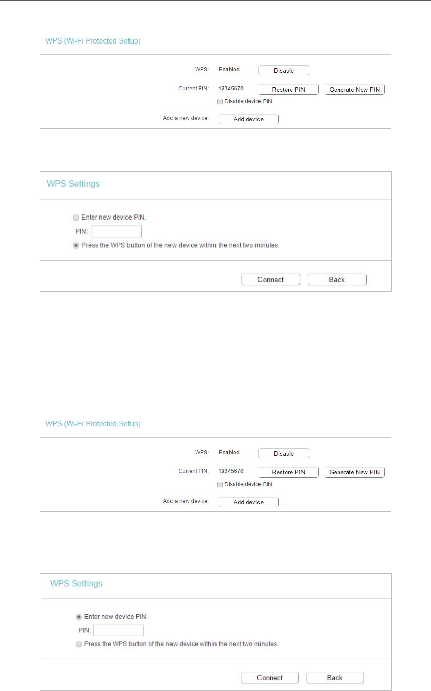
74
Chapter 5 &RQƮJXUHWKH5RXWHULQ$FFHVV3RLQW0RGH
2. Select Press the WPS button of the new device within the next two minutes and click
Connect.
3. Within two minutes, press the WPS button on your client device.
4. A success message will appear on the WPS page if the client device has been
successfully added to the router’s network.
Method TWO: Enter the Client’s PIN
1. Keep the WPS Status as Enabled and click Add Device.
2. Select Enter new device PIN, enter your client device’s current PIN in the PIN filed and
click Connect.
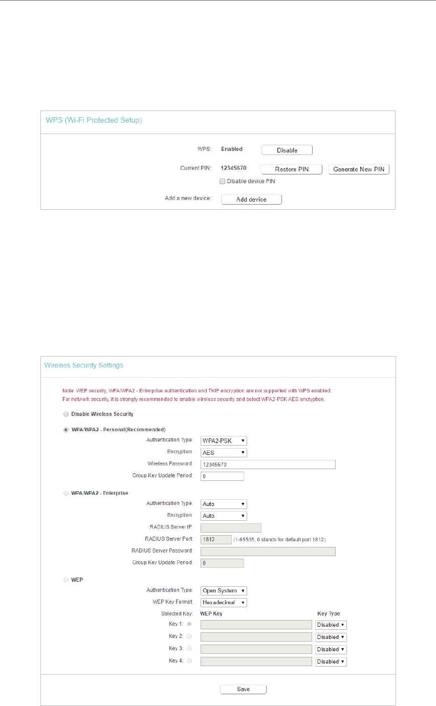
75
Chapter 5 &RQƮJXUHWKH5RXWHULQ$FFHVV3RLQW0RGH
3. A success message will appear on the WPS page if the client device has been
successfully added to the router’s network.
Method THREE: Enter the Router’s PIN
1. Keep the WPS Status as Enabled and get the Current PIN of the router.
2. Enter the router’s current PIN on your client device to join the router’s Wi-Fi network.
5. 6. 3. Wireless Security
1. Visit http://tplinkwifi.net, and log in with the username and password you set for the
router.
2. Go to Wireless > Wireless Security.
3. Configure the security settings of your wireless network and click Save.

76
Chapter 5 &RQƮJXUHWKH5RXWHULQ$FFHVV3RLQW0RGH
• Disable Wireless Security - The wireless security function can be enabled or disabled.
If disabled, wireless clients can connect to the router without a password. It’s strongly
recommended to choose one of the following modes to enable security.
• WPA-PSK/WPA2-Personal - It’s the WPA/WPA2 authentication type based on pre-
shared passphrase.
• Authentication Type - Select Auto, WPA-PSK or WPA2-PSK.
• Encryption - Select Auto, TKIP or AES.
• Wireless Password - Enter ASCII or Hexadecimal characters. For Hexadecimal,
the length should be between 8 and 64 characters; for ASCII, the length should
be between 8 and 63 characters.
• Group Key Update Period - Specify the group key update interval in seconds.
The value can be 0 or at least 30. Enter 0 to disable the update.
• WPA /WPA2-Enterprise - It’s based on Radius Server.
• Authentication Type - Select Auto, WPA or WPA2.
• Encryption - Select Auto, TKIP or AES.
• Radius Server IP - Enter the IP address of the Radius server.
• Radius Server Port - Enter the port that Radius server used.
• Radius Server Password - Enter the password for the Radius server.
• Group Key Update Period - Specify the group key update interval in seconds.
The value should be 30 or above. Enter 0 to disable the update.
• WEP - It is based on the IEEE 802.11 standard.
• Authentication Type - The default setting is Auto, which can select Shared
Key or Open System authentication type automatically based on the wireless
client’s capability and request.
• WEP Key Format - Hexadecimal and ASCII formats are provided here.
Hexadecimal format stands for any combination of hexadecimal digits (0-9,
a-f, A-F) in the specified length. ASCII format stands for any combination of
keyboard characters in the specified length.
• WEP Key (Password) - Select which of the four keys will be used and enter the
matching WEP key. Make sure these values are identical on all wireless clients
in your network.
• Key Type - Select the WEP key length (64-bit, 128-bit or 152-bit) for encryption.
Disabled means this WEP key entry is invalid.
• 64-bit - Enter 10 hexadecimal digits (any combination of 0-9, a-f and A-F. Null
key is not permitted) or 5 ASCII characters.
• 128-bit - Enter 26 hexadecimal digits (any combination of 0-9, a-f and A-F. Null
key is not permitted) or 13 ASCII characters.
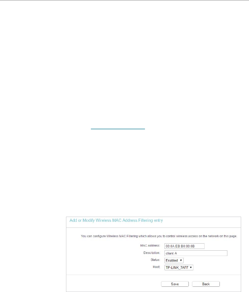
77
Chapter 5 &RQƮJXUHWKH5RXWHULQ$FFHVV3RLQW0RGH
5. 6. 4. Wireless MAC Filtering
Wireless MAC Filtering is used to deny or allow specific wireless client devices to access
your network by their MAC addresses.
Deny or allow specific wireless client devices to access my
network by their MAC addresses.
For example, you want the wireless client A with the MAC
address 00-0A-EB-B0-00-0B and the wireless client B with the
MAC address 00-0A-EB-00-07-5F to access the router, but
other wireless clients cannot access the router
1. Visit http://tplinkwifi.net, and log in with the username and
password you set for the router.
2. Go to Wireless > Wireless MAC Filtering.
3. Click Enable to enable the Wireless MAC Filtering function.
4. Select Allow the stations specified by any enabled entries in
the list to access as the filtering rule.
5. Delete all or disable all entries if there are any entries already.
6. Click Add New and fill in the blank.
1 ) Enter the MAC address 00-0A-EB-B0-00-0B/00-0A-EB-
00-07-5F in the MAC Address field.
2 ) Enter wireless client A/B in the Description field.
3 ) Select Enabled in the Status drop-down list.
4 ) Click Save and click Back.
7. The configured filtering rules should be listed as the picture
shows below.
I want to:
How
can I do
that?
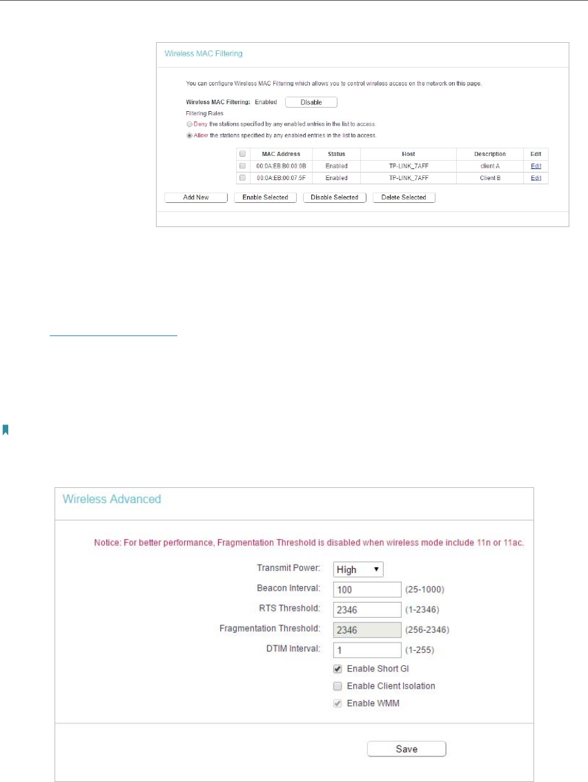
78
Chapter 5 &RQƮJXUHWKH5RXWHULQ$FFHVV3RLQW0RGH
Now only client A and client B can access your network.
5. 6. 5. Wireless Advanced
1. Visit http://tplinkwifi.net, and log in with the username and password you set for the
router.
2. Go to Wireless > Wireless Advanced.
3. Configure the advanced settings of your wireless network and click Save.
Note:
If you are not familiar with the setting items on this page, it’s strongly recommended to keep the provided default values;
otherwise it may result in lower wireless network performance.
• Transmit Power - Select High, Middle or Low which you would like to specify for the
router. High is the default setting and recommended.
• Beacon Interval - Enter a value between 40-1000 milliseconds for Beacon Interval
here. Beacon Interval value determines the time interval of the beacons. The beacons
are the packets sent by the router to synchronize a wireless network. The default
value is 100.
Done!

79
Chapter 5 &RQƮJXUHWKH5RXWHULQ$FFHVV3RLQW0RGH
• RTS Threshold - Here you can specify the RTS (Request to Send) Threshold. If the
packet is larger than the specified RTS Threshold size, the router will send RTS frames
to a particular receiving station and negotiate the sending of a data frame. The default
value is 2346.
• Fragmentation Threshold - This value is the maximum size determining whether
packets will be fragmented. Setting a low value for the Fragmentation Threshold may
result in poor network performance because of excessive packets. 2346 is the default
setting and is recommended.
• DTIM Interval - This value determines the interval of the Delivery Traffic Indication
Message (DTIM). A DTIM field is a countdown field informing clients of the next window
for listening to broadcast and multicast messages. When the router has buffered
broadcast or multicast messages for associated clients, it sends the next DTIM with
a DTIM Interval value. You can specify the value between 1-255 Beacon Intervals. The
default value is 1, which indicates the DTIM Interval is the same as Beacon Interval.
• Enable Short GI - It is recommended to enable this function, for it will increase the
data capacity by reducing the guard interval time.
• Enable Client Isolation - This function isolates all connected wireless stations so that
wireless stations cannot access each other through WLAN.
• Enable WMM - WMM function can guarantee the packets with high-priority messages
being transmitted preferentially. It is strongly recommended to enable this function.
5. 6. 6. Wireless Statistics
1. Visit http://tplinkwifi.net, and log in with the username and password you set for the
router.
2. Go to Wireless > Wireless Statistics to check the data packets sent and received by
each client device connected to the router.
• MAC Address - The MAC address of the connected wireless client.
• Current Status - The running status of the connected wireless client.
• Received Packets - Packets received by the wireless client.
• Sent Packets - Packets sent by the wireless client.
• SSID - SSID that the station associates with.
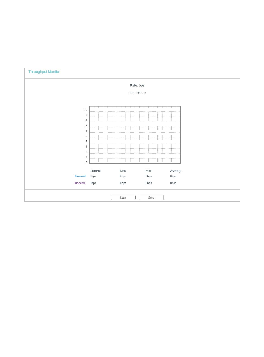
80
Chapter 5 &RQƮJXUHWKH5RXWHULQ$FFHVV3RLQW0RGH
5. 6. 7. Throughout Monitor
1. Visit http://tplinkwifi.net, and log in with the username and password you set for the
router.
2. Go to Wireless > Throughout Monitor to watch wireless throughput info
• Rate - The Throughput unit.
• Run Time - How long this funtion is running.
• Transmit - Wireless transmit rate information.
• Receive - Wireless receive rate information.
Click Start to start wireless throughput monitor.
Click Stop to stop wireless throughput monitor.
5. 7. Guest Network
Guest Network allows you to provide Wi-Fi access for guests without disclosing your
host network. When you have guests in your house, apartment, or workplace, you can
create a guest network for them. In addition, you can customize guest network settings
to ensure network security and privacy.
1. Visit http://tplinkwifi.net, and log in with the username and password you set for the
router.
2. Go to Guest Network.
3. Enable the Guset Network function.
4. Create a network name for your guest network.
5. Select the Security type and create the Password of the guest network.
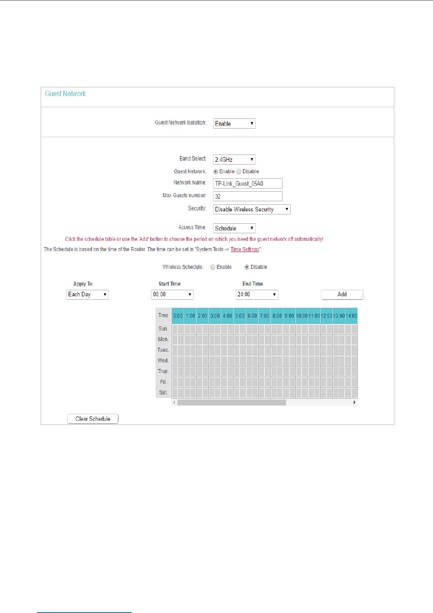
81
Chapter 5 &RQƮJXUHWKH5RXWHULQ$FFHVV3RLQW0RGH
6. Select Schedule from the Access Time drop-down list and customize it for the
guest network.
7. Click Save.
• Guest Network Isolation - If enabled, guests are isolated from each other.
5. 8. DHCP
By default, the DHCP (Dynamic Host Configuration Protocol) Server is enabled and the
router acts as a DHCP server; it dynamically assigns TCP/IP parameters to client devices
from the IP Address Pool. You can change the settings of DHCP Server if necessary,
and you can reserve LAN IP addresses for specified client devices.
5. 8. 1. DHCP Settings
1. Visit http://tplinkwifi.net, and log in with the username and password you set for the
router.
2. Go to DHCP > DHCP Settings.
3. Specify DHCP server settings and click Save.
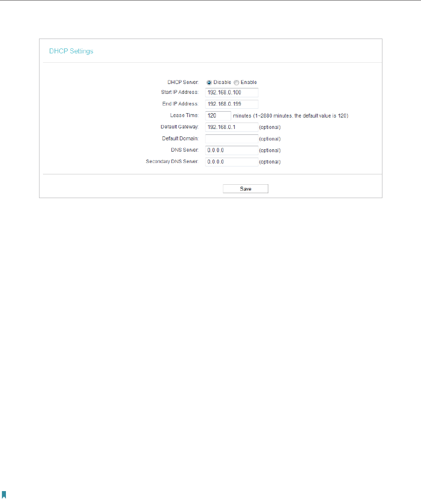
82
Chapter 5 &RQƮJXUHWKH5RXWHULQ$FFHVV3RLQW0RGH
• DHCP Server - Enable or disable the DHCP server. If disabled, you must have another
DHCP server within your network or else you must configure the computer manually.
• Start IP Address - Specify an IP address for the DHCP Server to start with when
assigning IP addresses. 192.168.0.100 is the default start address.
• End IP Address - Specify an IP address for the DHCP Server to end with when assigning
IP addresses. 192.168.0.199 is the default end address.
• Address Lease Time - The Address Lease Time is the amount of time a network user
will be allowed to connect to the router with the current dynamic IP Address. When
time is up, the user will be automatically assigned a new dynamic IP address. The
range of the time is 1 ~ 2880 minutes. The default value is 1.
• Default Gateway (Optional) - It is suggested to input the IP address of the LAN port of
the router. The default value is 192.168.0.1.
• Default Domain (Optional) - Input the domain name of your network.
• DNS Server (Optional) - Input the DNS IP address provided by your ISP.
• Secondary DNS Server (Optional) - Input the IP address of another DNS server if your
ISP provides two DNS servers.
Note:
• To use the DHCP server function of the router, you must configure all computers on the LAN as Obtain
an IP Address automatically.
• When you choose Smart IP (DHCP) in Network > LAN, the DHCP Server function will be disabled. You will
see the page as below.
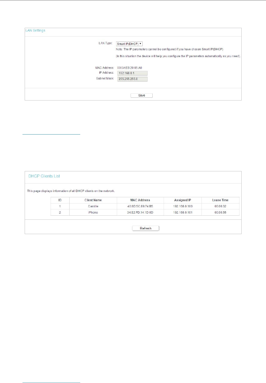
83
Chapter 5 &RQƮJXUHWKH5RXWHULQ$FFHVV3RLQW0RGH
5. 8. 2. DHCP Client List
1. Visit http://tplinkwifi.net, and log in with the username and password you set for the
router.
2. Go to DHCP > DHCP Client List to view the information of the clients connected to
the router.
• Client Name - The name of the DHCP client.
• MAC Address - The MAC address of the DHCP client.
• Assigned IP - The IP address that the outer has allocated to the DHCP client.
• Lease Time - The time of the DHCP client leased. After the dynamic IP address has
expired, a new dynamic IP address will be automatically assigned to the user.
You cannot change any of the values on this page. To update this page and show the
current attached devices, click Refresh.
5. 8. 3. Address Reservation
You can reserve an IP address for a specific client. When you specify a reserved IP
address for a PC on the LAN, this PC will always receive the same IP address each time
when it accesses the DHCP server.
1. Visit http://tplinkwifi.net, and log in with the username and password you set for the
router.
2. Go to DHCP > Address Reservation.
3. Click Add New and fill in the blank.
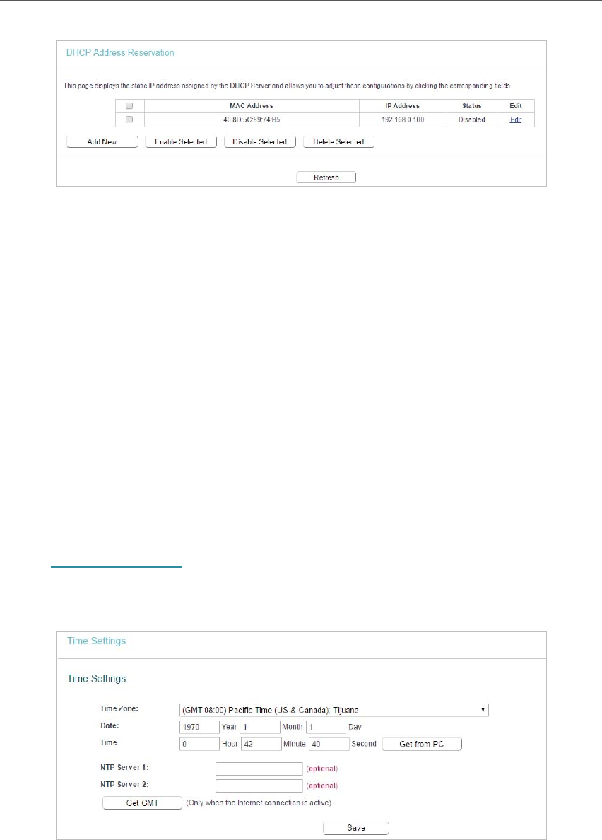
84
Chapter 5 &RQƮJXUHWKH5RXWHULQ$FFHVV3RLQW0RGH
1 ) Enter the MAC address (in XX-XX-XX-XX-XX-XX format.) of the client for which
you want to reserve an IP address.
2 ) Enter the IP address (in dotted-decimal notation) which you want to reserve for
the client.
3 ) Leave the Status as Enabled.
4 ) Click Save.
5. 9. System Tools
5. 9. 1. Time Settings
This page allows you to set the time manually or to configure automatic time
synchronization. The Router can automatically update the time from an NTP server via
the internet.
1. Visit http://tplinkwifi.net, and log in with the username and password you set for the
router.
2. Go to System Tools > Time Settings.
¾To set time manually:
1. Select your local time zone.
2. Enter the Date in Month/Day/Year format.
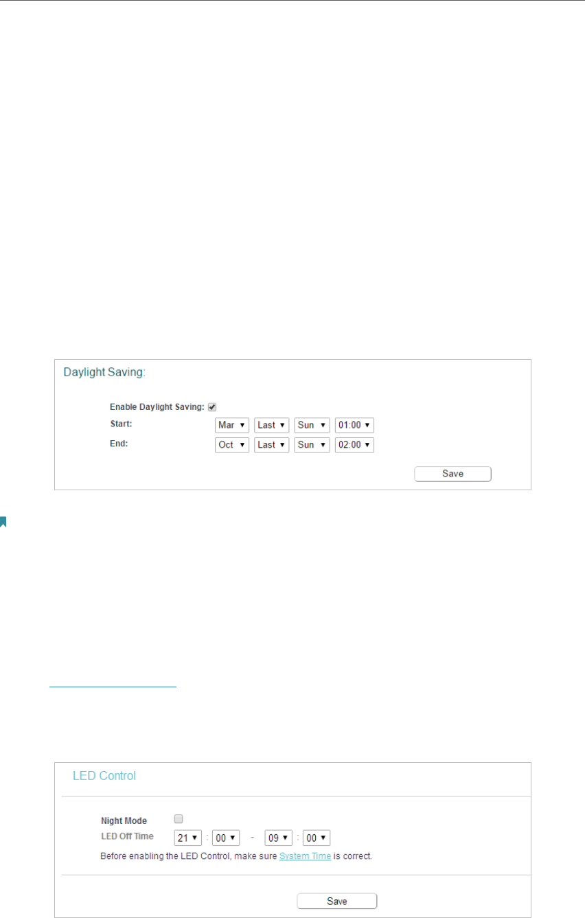
85
Chapter 5 &RQƮJXUHWKH5RXWHULQ$FFHVV3RLQW0RGH
3. Enter the Time in Hour/Minute/Second format.
4. Click Save.
¾To set time automatically:
5. Select your local time zone.
6. Enter the address or domain of the NTP Server I or NTP Server II.
7. Click Get GMT to get time from the internet if you have connected to the internet.
¾To set Daylight Saving Time:
1. Select Enable DaylightSaving.
2. Select the start time from the drop-down list in the Start field.
3. Select the end time from the drop-down list in the End field.
4. Click Save.
Note:
This setting will be used for some time-based functions such as firewall. You must specify your time zone once you log
in to the router successfully; otherwise, time-based functions will not take effect.
5. 9. 2. LED Control
The LED Control allows you to turn on or off the LEDs on your device according to a
specific time schedule.
1. Visit http://tplinkwifi.net, and log in with the username and password you set for the
router.
2. Go to System Tools > LED Control.
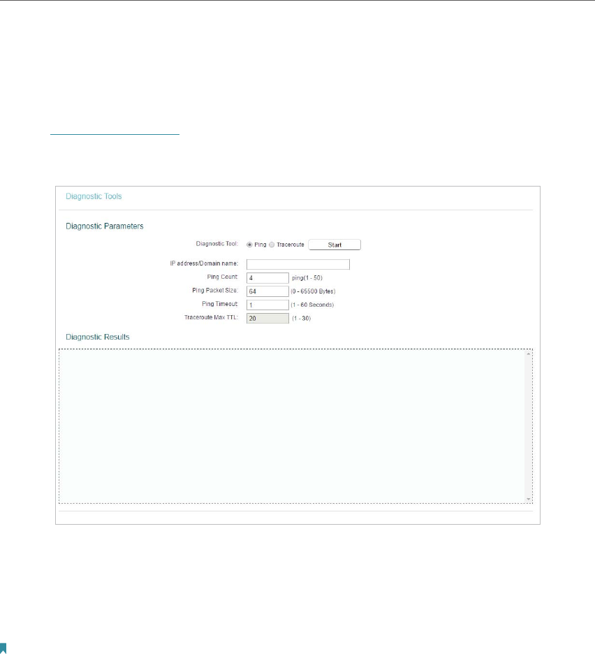
86
Chapter 5 &RQƮJXUHWKH5RXWHULQ$FFHVV3RLQW0RGH
5. 9. 3. Diagnostic
Diagnostic is used to test the connectivity between the router and the host or other
network devices.
1. Visit http://tplinkwifi.net, and log in with the username and password you set for the
router.
2. Go to System Tools > Diagnostic.
• Diagnostic Tool - Select one diagnostic tool.
• Ping - This diagnostic tool troubleshoots connectivity, reachability, and name
resolution to a given host or gateway.
• Tracerouter - This diagnostic tool tests the performance of a connection.
Note:
You can use ping/traceroute to test both numeric IP address or domain name. If pinging/tracerouting the IP address is
successful, but pinging/tracerouting the domain name is not, you might have a name resolution problem. In this case,
ensure that the domain name you are specifying can be resolved by using Domain Name System (DNS) queries.
• IP Address/Domain Name - Enter the destination IP address (such as 192.168.0.1) or
Domain name (such as www.tp-link.com).
• Pings Count - The number of Ping packets for a Ping connection.
• Ping Packet Size - The size of Ping packet.
• Ping Timeout - Set the waiting time for the reply of each Ping packet. If there is no
reply in the specified time, the connection is overtime.
• Traceroute Max TTL - The max number of hops for a Traceroute connection.
3. Click Start to check the connectivity of the internet.
4. The Diagnostic Results page displays the diagnosis result. If the result is similar to
the following figure, the connectivity of the internet is fine.
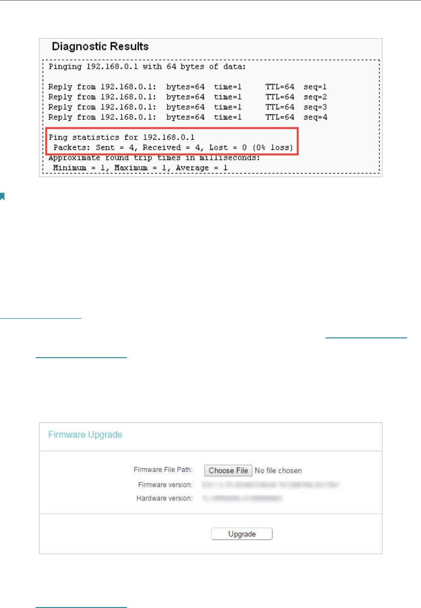
87
Chapter 5 &RQƮJXUHWKH5RXWHULQ$FFHVV3RLQW0RGH
Note: Only one user can use this tool at one time. Options “Number of Pings”, “Ping Size” and “Ping Timeout” are used
for the Ping function. Option “Tracert Hops” is used for the Tracert function.
5. 9. 4. Firmware Upgrade
TP-Link is dedicated to improving and richening the product features, giving users
a better network experience. We will release the latest firmware at TP-Link official
website. You can download the latest firmware file from the Support page of our website
www.tp-link.com and upgrade the firmware to the latest version.
1. Download the latest firmware file for the router from our website www.tp-link.com.
2. Visit http://tplinkwifi.net, and log in with the username and password you set for the
router.
3. Go to System Tools > Firmware Upgrade.
4. Click Choose File to locate the downloaded firmware file, and click Upgrade.
5. 9. 5. Factory Defaults
1. Visit http://tplinkwifi.net, and log in with the username and password you set for the
router.

88
Chapter 5 &RQƮJXUHWKH5RXWHULQ$FFHVV3RLQW0RGH
2. Go to System Tools > Factory Defaults. Click Restore to reset all settings to the
default values.
• The default Username: admin
• The default
Password: admin
• The default
IP Address: 192.168.0.1
• The default
Subnet Mask: 255.255.255.0
5. 9. 6. Backup & Restore
The configuration settings are stored as a configuration file in the router. You can
backup the configuration file in your computer for future use and restore the router to
the previous settings from the backup file when needed.
1. Visit http://tplinkwifi.net, and log in with the username and password you set for the
router.
2. Go to System Tools > Backup & Restore.
¾To backup configuration settings:
Click Backup to save a copy of the current settings in your local computer. A “.bin“ file
of the current settings will be stored in your computer.
¾To restore configuration settings:
1. Click Choose File to locate the backup configuration file stored in your computer, and
click Restore.
2. Wait a few minutes for the restoring and rebooting.
Note:
During the restoring process, do not power off or reset the router.
5. 9. 7. Reboot
1. Visit http://tplinkwifi.net, and log in with the username and password you set for the
router.
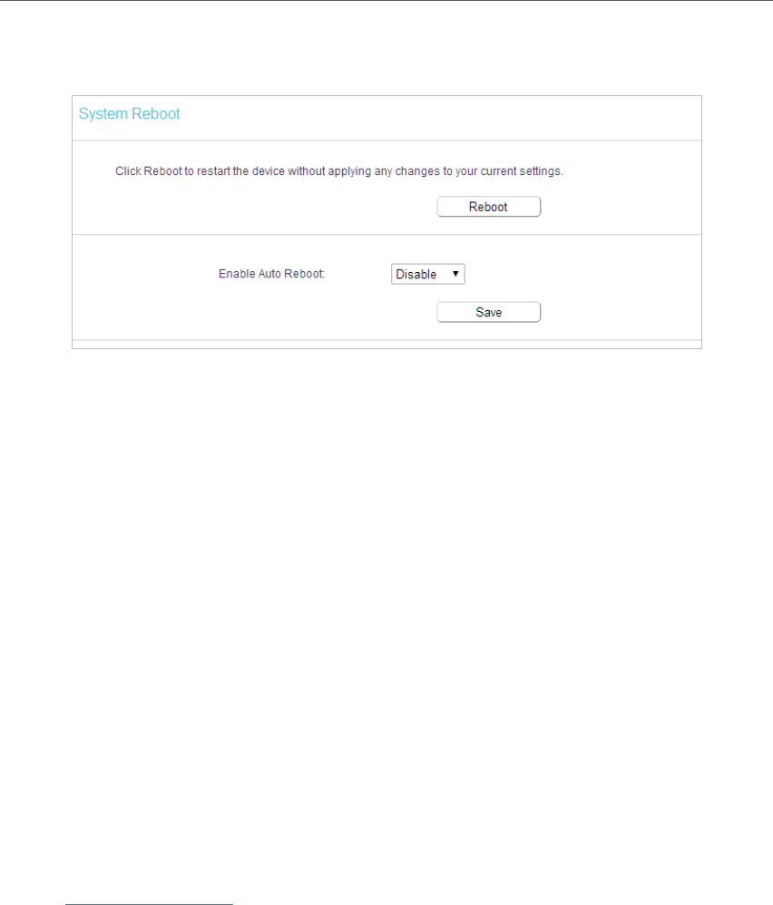
89
Chapter 5 &RQƮJXUHWKH5RXWHULQ$FFHVV3RLQW0RGH
2. Go to System Tools > Reboot, and you can restart your router.
3. Enable the auto reboot function as needed.
• Disable - Disable the auto reboot function.
• Timeout - Specify a time period(1-72 hours), then the router will reboot
automatically after every this interval.
• Schedule - The router will reboot automatically according to a specific time
schedule.
Some settings of the router will take effect only after rebooting, including:
• Change the LAN IP Address (system will reboot automatically).
• Change the DHCP Settings.
• Change the Working Modes.
• Change the Web Management Port.
• Upgrade the firmware of the router (system will reboot automatically).
• Restore the router to its factory defaults (system will reboot automatically).
• Update the configuration with the file (system will reboot automatically).
5. 9. 8. Administrator
1. Visit http://tplinkwifi.net, and log in with the username and password you set for the
router.
2. Go to System Tools > Administrator, and you can change the factory default username
and password of the router, and manage your router from a remote location via the
internet.
¾To view and change the account settings:
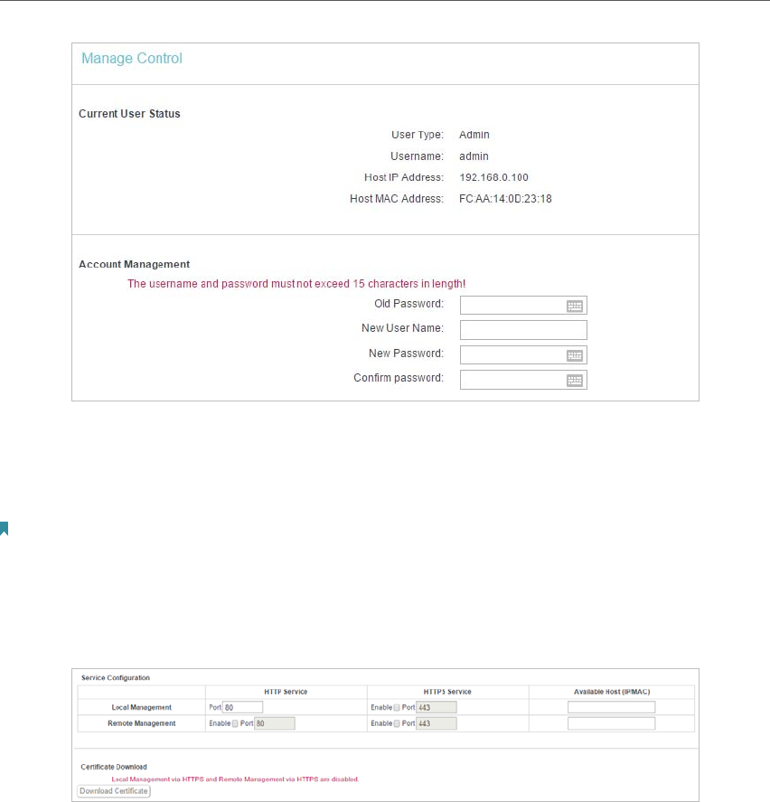
90
Chapter 5 &RQƮJXUHWKH5RXWHULQ$FFHVV3RLQW0RGH
It is strongly recommended that you change the default username and password of the
router, for all users that try to access the router’s web mangement page or Quick Setup
will be prompted for the router’s username and password.
Note:
The new username and password must not exceed 15 characters and not include any spacing.
¾To manage your Router from a remote location via the internet:
1. Specify the remote management web port number and click Save.
• Web Management Port - The default remote management web port number is
80. For greater security, you can change the remote management web port to
a number between 1024 and 65535 but do not use the number of any common
service port.
• Remote Management IP Address - This is the current address you will use when
accessing your router from the internet. This function is disabled when the IP
address is set to the default value of 0.0.0.0. To enable this function change
0.0.0.0 to a valid IP address. If set to 255.255.255.255, then all the hosts can
access the router from internet.
• Certificate - A file that provides you with authentication information. Download
and install the certificate for Local/Remote Management via HTTPS if you need
it. Once the certificate is installed, warnings will not pop up when you access
the router via HTTPS.

91
Chapter 5 &RQƮJXUHWKH5RXWHULQ$FFHVV3RLQW0RGH
2. Enter your router’s WAN IP address into your browser’s address bar, followed by a
colon and the custom port number you set in the Web Management Port box. For
example, if your Router’s WAN address is 202.96.12.8 and you use port number 8080,
enter http://202.96.12.8:8080 in your browser.
3. Enter the router’s password to access the web mangement page remotely.
Note:
• Be sure to change the router’s default password to a secure password.
• If the web management port conflicts with the one used for a Virtual Server entry, the entry will be
automatically disabled after the setting is saved.
5. 9. 9. System Log
1. Visit http://tplinkwifi.net, and log in with the username and password you set for the
router.
2. Go to System Tools > System Log, and you can view the logs of the router.
• Loge Type -By selecting the log type, only logs of this type will be shown.
• Log Level - By selecting the log level, only logs of this level will be shown.
• Refresh - Refresh the page to show the latest log list.
• Clear Log - All the logs will be deleted from the router permanently, not just from the
page.
5. 10. Log Out
Click Logout at the bottom of the main menu, and you will log out of the web page and
be directed to the login window.

Chapter 6
Configure the Router in
Range Extender Mode
This chapter presents how to configure the various features of the router in Range
Extender Mode.
It contains the following sections:
• Status
• Quick Setup
• Operation Mode
• Network
• Dual Band Selection
• Wireless(2.4GHz or 5GHz)
• DHCP
• System Tools
• Log Out
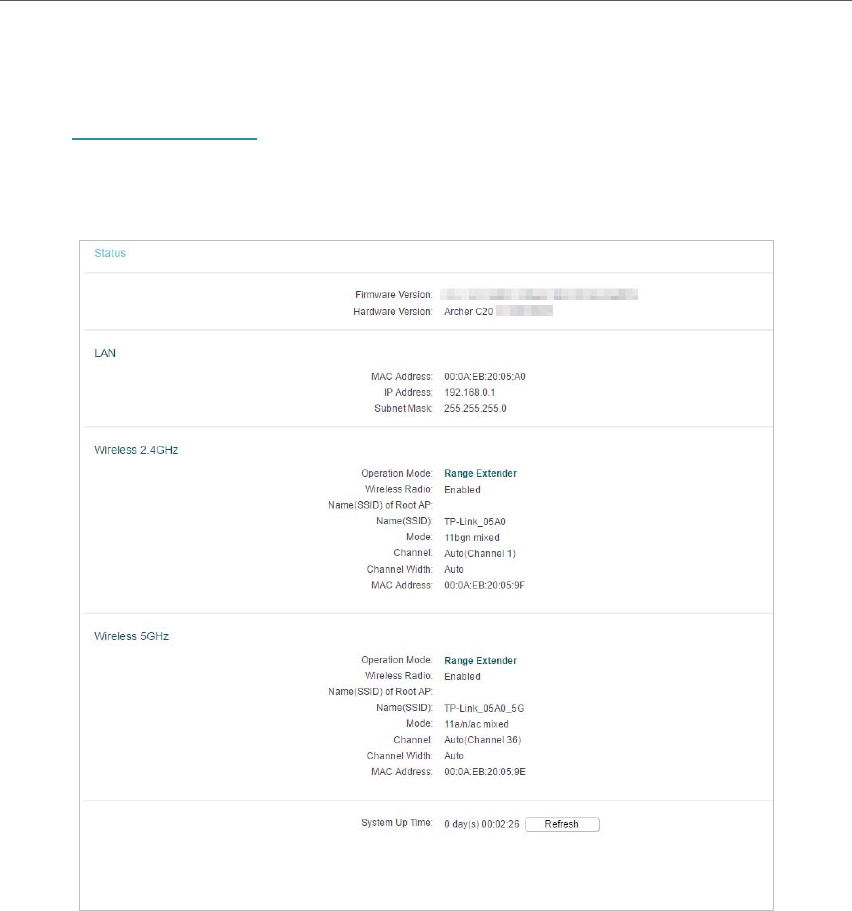
93
Chapter 6 Configure the Router in Range Extender Mode
6. 1. Status
1. Visit http://tplinkwifi.net, and log in with the username and password you set for the
router.
2. Go to Status. You can view the current status information of the router.
• Firmware Version - The version information of the router’s firmware.
• Hardware Version - The version information of the router’s hardware.
• LAN - This field displays the current settings of the LAN, and you can configure them
on the Network > LAN page.
• MAC address - The physical address of the router.
• IP address - The LAN IP address of the router.
• Subnet Mask - The subnet mask associated with the LAN IP address.
• Wireless 2.4GHz/5GHz - This field displays the basic information or status of the
wireless function, and you can configure them on the Wireless > Basic Settings page.
• Operation Mode - The current wireless working mode in use.
• Wireless Radio - Indicates whether the wireless radio feature of the Router is
enabled or disabled.
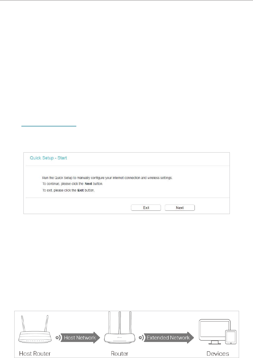
94
Chapter 6 Configure the Router in Range Extender Mode
• Name(SSID) - The SSID of the Router.
• Mode - The current wireless mode which the router works on.
• Channel - The current wireless channel in use.
• Channel Width - The current wireless channel width in use.
• MAC Address - The physical address of the router.
• System Up Time - The length of time since the AP was last powered on or reset. Click
Refresh to get the latest status and settings of the AP.
6. 2. Quick Setup
1. Visit http://tplinkwifi.net, and log in with the username and password you set for the
router.
2. Go to Quick Setup.
3. Click Next to start. Then follow the step-by-step instructions to connect your router
to the internet.
6. 3. Operation Mode
The router supports three operation modes: Wireless Router mode, Access Point mode
and Range Extender. In Range Extender mode, the device can copy and reinforce the
existing wireless signal to extend the coverage of the signal, especially for a large space
to eliminate signal-blind corners. To switch to Range Extender mode:
1. Place the router next to your host router and power it on.
2. Connect a computer to the router via an Ethernet cable or wirelessly by using the
SSID (network name) and Wireless Password printed on the label at the bottom of
the router.
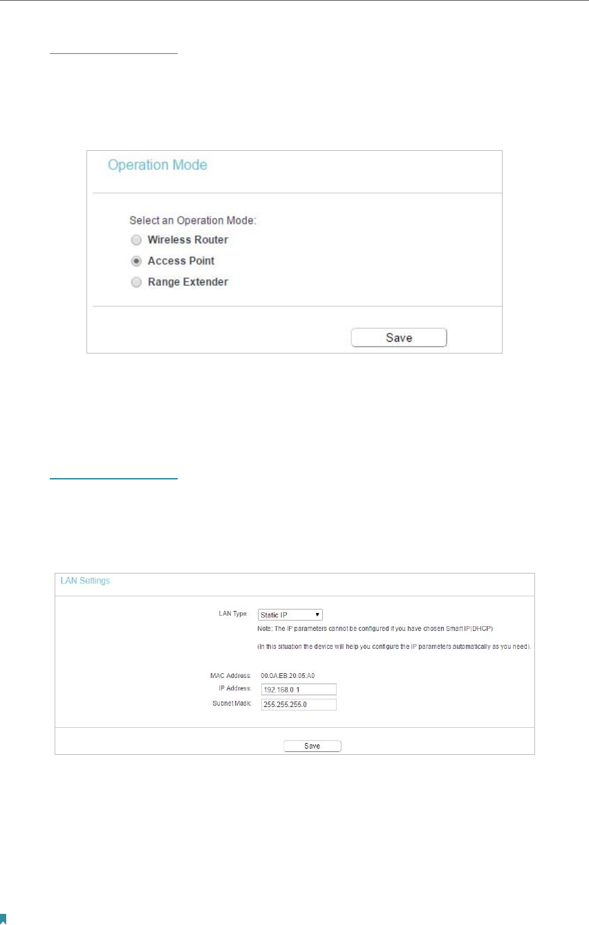
95
Chapter 6 Configure the Router in Range Extender Mode
3. Visit http://tplinkwifi.net, and log in with the username and password you set for the
router.
4. Go to Operation Mode.
5. Select the Range Extender mode and click Save.
6. 4. Network
6. 4. 1. LAN
1. Visit http://tplinkwifi.net, and log in with the username and password you set for the
router.
2. Go to Network > LAN.
3. Configure the IP parameters of the LAN and click Save.
• LAN Type - Select Smart IP(DHCP) to get IP address from DHCP server, or select
static IP to configure IP address manually.
• MAC Address - The physical address of the LAN ports. The value can not be changed.
• IP Address - Enter the IP address in dotted-decimal notation of your router.
• Subnet Mask - An address code that determines the size of the network. Normally
255.255.255.0 is used as the subnet mask.
Note:
• If you change the IP address, you must use the new IP address to login to the device.
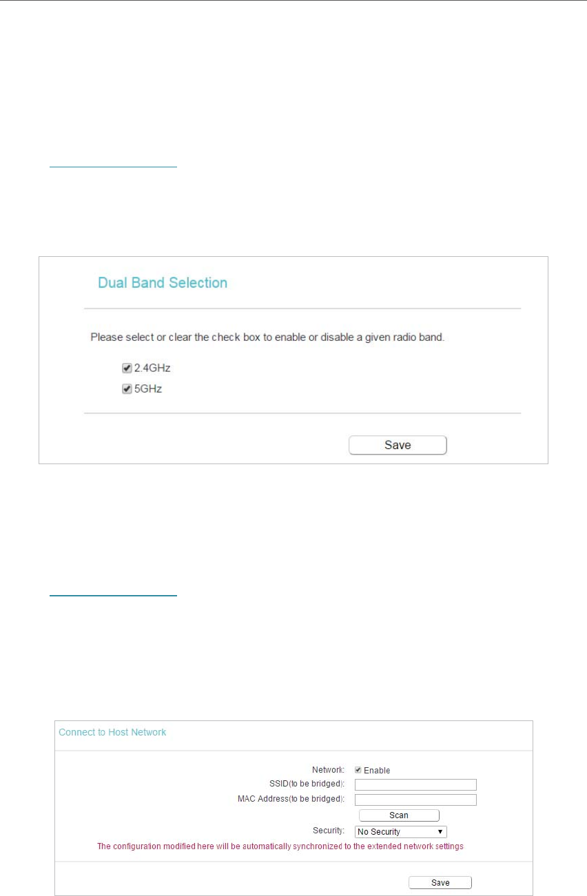
96
Chapter 6 Configure the Router in Range Extender Mode
• If you select the type of smart IP(DHCP), the DHCP server in this device will not startup.
• If the new IP address you set is not in the same subnet with the previous one, the IP Address pool in the
DHCP server will be configured automatically.
6. 5. Dual Band Selection
1. Visit http://tplinkwifi.net, and log in with the username and password you set for the
router.
2. Go to Dual Band Selection.
3. Select the working radio band as needed and click Save.
6. 6. Wireless(2.4GHz or 5GHz)
6. 6. 1. Connect to Host Network
1. Visit http://tplinkwifi.net, and log in with the username and password you set for the
router.
2. Go to Wireless > Connect to Network.
3. Enable the Network function.
4. Configure the basic settings for the wireless network and click Save.
• SSID(to be bridged) - Enter the case-sensitive SSID of the host network which the
extender will be connecting to, or click Scan and select a Wi-Fi network.

97
Chapter 6 Configure the Router in Range Extender Mode
• MAC Address(to be bridged) - Enter the MAC Address of the host network which the
extender will be connecting to, or click Scan and select a Wi-Fi network.
• Scan - Click to scan and display all available Wi-Fi networks within range that you
want the extender to connect to. Once a network is selected, the SSID and security
settings of that network will automatically populate.
• Security - Select one of the security options to match with the host network.
• No Security - This option disables the wireless security.
• WPA-PSK - This option supports implementation of the WPA (Wi-Fi Protected
Access) standard. It is recommended. For Password, it should be between 8
and 63 characters.
• WPA2-PSK - This option supports implementation of the WPA2 (Wi-Fi Protected
Access) standard. It is also recommended. For Password, it should be between
8 and 63 characters.
• WEP - This option is the most basic form of wireless security that can be used
if your client devices can only access wireless using WEP (Wired Equivalent
Privacy). Enter the matching WEP key information for your network.
6. 6. 2. Connect to Host Network
In Range Extender mode, the device will relay data to an associated root AP. AP function
is enabled meanwhile. The wireless range extender relays signal between its stations
and the root AP for greater wireless range.
1. Visit http://tplinkwifi.net, and log in with the username and password you set for the
router.
2. Go to Wireless > Connect to Network.
3. Enable the Extended Network function.
4. Configure the basic settings for the network and click Save.
• Extended 2.4GHz SSID - Either use the Copy Host SSID button to automatically copy
the main router/AP’s SSID or enter a new name (up to 32 characters long). This field is
case-sensitive.
• Copy Host SSID - Click to copy the Host SSID. When selected, the extended network
will share the SSID of your host network.

98
Chapter 6 Configure the Router in Range Extender Mode
• Extended 2.4GHz Security - Select one of the security options to set local extended
wireless network.
• No Security - This option disables the wireless security.
• WPA-PSK/WPA2-PSK - This option supports multiple implementation of the
WPA (Wi-Fi Protected Access) standard, such as WPA and WPA2.
• WEP - This option is the most basic form of wireless security that can be used
if your client devices can only access wireless using WEP (Wired Equivalent
Privacy).
6. 6. 3. Wireless MAC Filtering
Wireless MAC Filtering is used to deny or allow specific wireless client devices to access
your network by their MAC addresses.
Deny or allow specific wireless client devices to access my
network by their MAC addresses.
For example, you want the wireless client A with the MAC
address 00-0A-EB-B0-00-0B and the wireless client B with the
MAC address 00-0A-EB-00-07-5F to access the router, but
other wireless clients cannot access the router
1. Visit http://tplinkwifi.net, and log in with the username and
password you set for the router.
2. Go to Wireless > Wireless MAC Filtering.
3. Click Enable to enable the Wireless MAC Filtering function.
4. Select Allow the stations specified by any enabled entries in
the list to access as the filtering rule.
5. Delete all or disable all entries if there are any entries already.
6. Click Add New and fill in the blank.
I want to:
How
can I do
that?
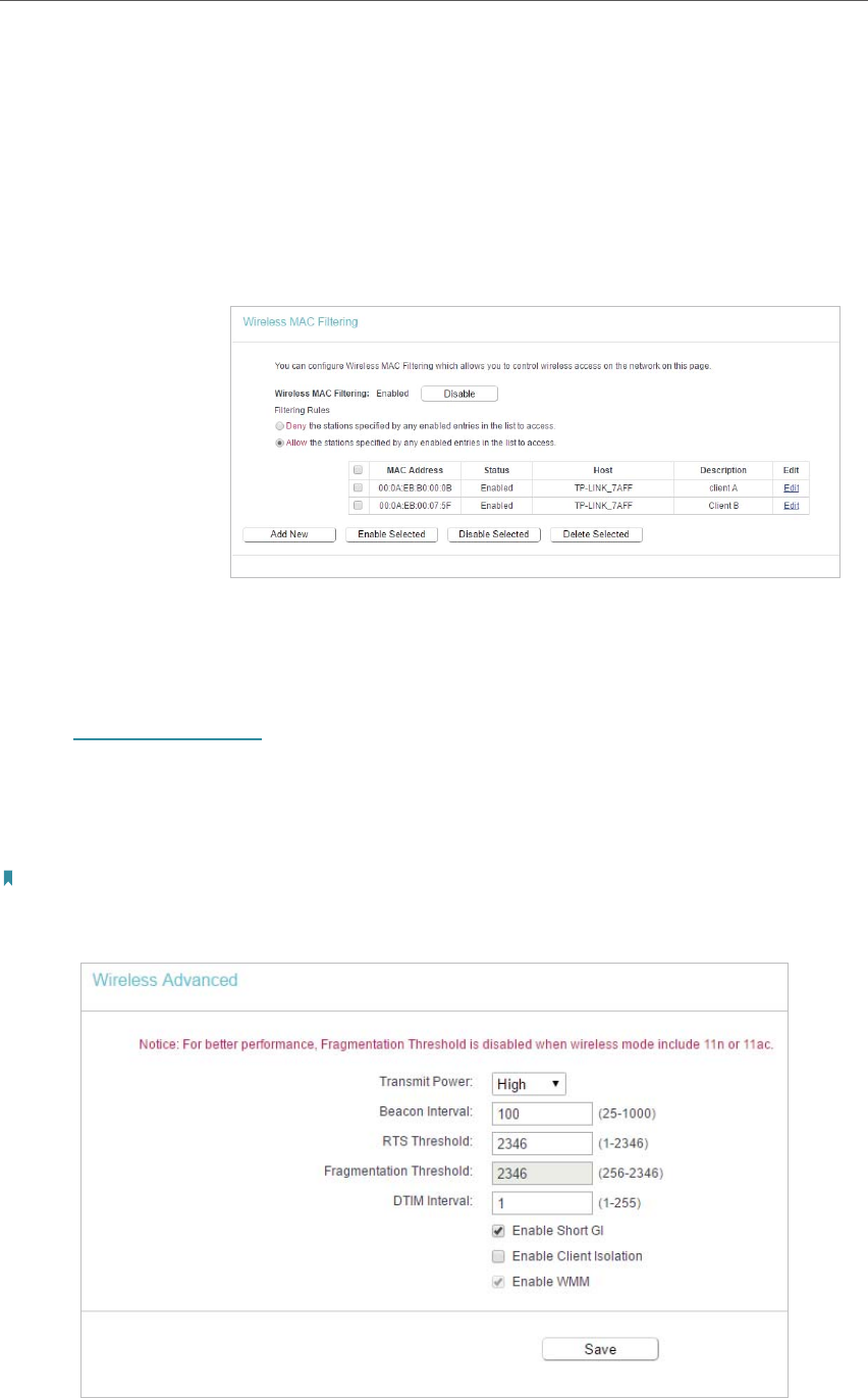
99
Chapter 6 Configure the Router in Range Extender Mode
1 ) Enter the MAC address 00-0A-EB-B0-00-0B/00-0A-EB-
00-07-5F in the MAC Address field.
2 ) Enter wireless client A/B in the Description field.
3 ) Select Enabled in the Status drop-down list.
4 ) Click Save and click Back.
7. The configured filtering rules should be listed as the picture
shows below.
Now only client A and client B can access your network.
6. 6. 4. Wireless Advanced
1. Visit http://tplinkwifi.net, and log in with the username and password you set for the
router.
2. Go to Wireless > Wireless Advanced.
3. Configure the advanced settings of your wireless network and click Save.
Note:
If you are not familiar with the setting items on this page, it’s strongly recommended to keep the provided default values;
otherwise it may result in lower wireless network performance.
Done!

100
Chapter 6 Configure the Router in Range Extender Mode
• Transmit Power - Select High, Middle or Low which you would like to specify for the
router. High is the default setting and recommended.
• Beacon Interval - Enter a value between 40-1000 milliseconds for Beacon Interval
here. Beacon Interval value determines the time interval of the beacons. The beacons
are the packets sent by the router to synchronize a wireless network. The default
value is 100.
• RTS Threshold - Here you can specify the RTS (Request to Send) Threshold. If the
packet is larger than the specified RTS Threshold size, the router will send RTS frames
to a particular receiving station and negotiate the sending of a data frame. The default
value is 2346.
• Fragmentation Threshold - This value is the maximum size determining whether
packets will be fragmented. Setting a low value for the Fragmentation Threshold may
result in poor network performance because of excessive packets. 2346 is the default
setting and is recommended.
• DTIM Interval - This value determines the interval of the Delivery Traffic Indication
Message (DTIM). A DTIM field is a countdown field informing clients of the next window
for listening to broadcast and multicast messages. When the router has buffered
broadcast or multicast messages for associated clients, it sends the next DTIM with
a DTIM Interval value. You can specify the value between 1-255 Beacon Intervals. The
default value is 1, which indicates the DTIM Interval is the same as Beacon Interval.
• Enable Short GI - It is recommended to enable this function, for it will increase the
data capacity by reducing the guard interval time.
• Enable Client Isolation - This function isolates all connected wireless stations so that
wireless stations cannot access each other through WLAN.
• Enable WMM - WMM function can guarantee the packets with high-priority messages
being transmitted preferentially. It is strongly recommended to enable this function.
6. 6. 5. Wireless Statistics
1. Visit http://tplinkwifi.net, and log in with the username and password you set for the
router.
2. Go to Wireless > Wireless Statistics to check the data packets sent and received by
each client device connected to the router.
• MAC Address - The MAC address of the connected wireless client.
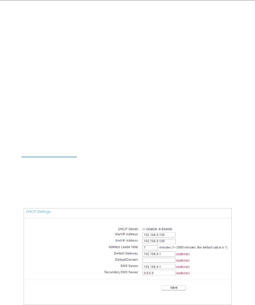
101
Chapter 6 Configure the Router in Range Extender Mode
• Current Status - The running status of the connected wireless client.
• Received Packets - Packets received by the wireless client.
• Sent Packets - Packets sent by the wireless client.
• SSID - SSID that the station associates with.
6. 7. DHCP
By default, the DHCP (Dynamic Host Configuration Protocol) Server is enabled and the
router acts as a DHCP server; it dynamically assigns TCP/IP parameters to client devices
from the IP Address Pool. You can change the settings of DHCP Server if necessary,
and you can reserve LAN IP addresses for specified client devices.
6. 7. 1. DHCP Settings
1. Visit http://tplinkwifi.net, and log in with the username and password you set for the
router.
2. Go to DHCP > DHCP Settings.
3. Specify DHCP server settings and click Save.
• DHCP Server - Enable or disable the DHCP server. If disabled, you must have another
DHCP server within your network or else you must configure the computer manually.
• Start IP Address - Specify an IP address for the DHCP Server to start with when
assigning IP addresses. 192.168.0.100 is the default start address.
• End IP Address - Specify an IP address for the DHCP Server to end with when assigning
IP addresses. 192.168.0.199 is the default end address.
• Address Lease Time - The Address Lease Time is the amount of time a network user
will be allowed to connect to the router with the current dynamic IP Address. When
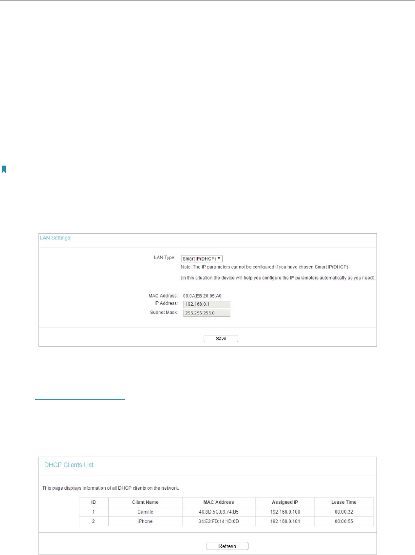
102
Chapter 6 Configure the Router in Range Extender Mode
time is up, the user will be automatically assigned a new dynamic IP address. The
range of the time is 1 ~ 2880 minutes. The default value is 1.
• Default Gateway (Optional) - It is suggested to input the IP address of the LAN port of
the router. The default value is 192.168.0.1.
• Default Domain (Optional) - Input the domain name of your network.
• DNS Server (Optional) - Input the DNS IP address provided by your ISP.
• Secondary DNS Server (Optional) - Input the IP address of another DNS server if your
ISP provides two DNS servers.
Note:
• To use the DHCP server function of the router, you must configure all computers on the LAN as Obtain
an IP Address automatically.
• When you choose Smart IP (DHCP) in Network > LAN, the DHCP Server function will be disabled. You will
see the page as below.
6. 7. 2. DHCP Client List
1. Visit http://tplinkwifi.net, and log in with the username and password you set for the
router.
2. Go to DHCP > DHCP Client List to view the information of the clients connected to
the router.
• Client Name - The name of the DHCP client.
• MAC Address - The MAC address of the DHCP client.
• Assigned IP - The IP address that the outer has allocated to the DHCP client.
• Lease Time - The time of the DHCP client leased. After the dynamic IP address has
expired, a new dynamic IP address will be automatically assigned to the user.
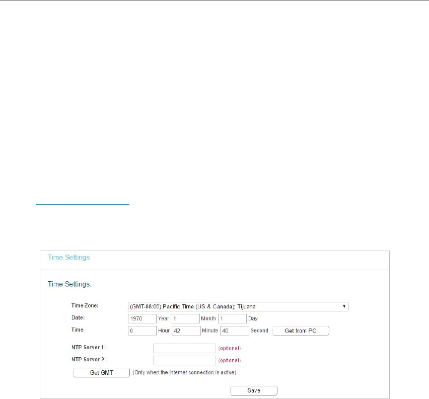
103
Chapter 6 Configure the Router in Range Extender Mode
You cannot change any of the values on this page. To update this page and show the
current attached devices, click Refresh.
6. 8. System Tools
6. 8. 1. Time Settings
This page allows you to set the time manually or to configure automatic time
synchronization. The Router can automatically update the time from an NTP server via
the internet.
1. Visit http://tplinkwifi.net, and log in with the username and password you set for the
router.
2. Go to System Tools > Time Settings.
¾To set time manually:
1. Select your local time zone.
2. Enter the Date in Month/Day/Year format.
3. Enter the Time in Hour/Minute/Second format.
4. Click Save.
¾To set time automatically:
5. Select your local time zone.
6. Enter the address or domain of the NTP Server I or NTP Server II.
7. Click Get GMT to get time from the internet if you have connected to the internet.
¾To set Daylight Saving Time:
1. Select Enable DaylightSaving.
2. Select the start time from the drop-down list in the Start field.
3. Select the end time from the drop-down list in the End field.
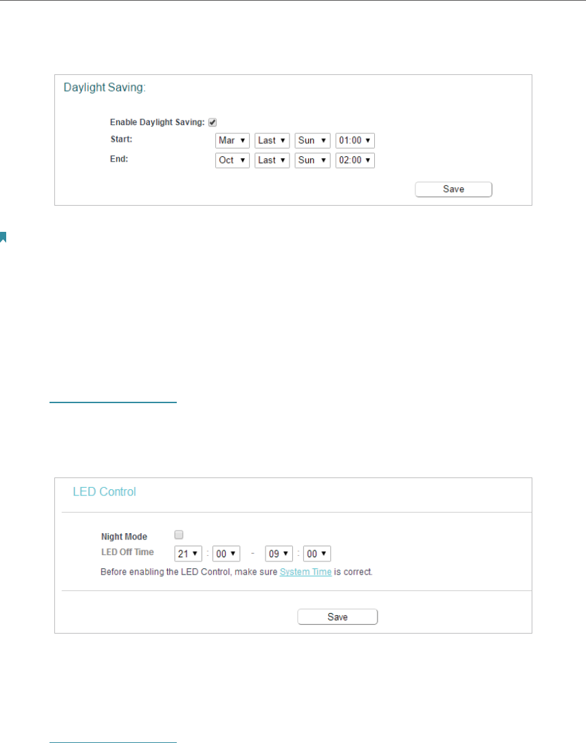
104
Chapter 6 Configure the Router in Range Extender Mode
4. Click Save.
Note:
This setting will be used for some time-based functions such as firewall. You must specify your time zone once you log
in to the router successfully; otherwise, time-based functions will not take effect.
6. 8. 2. LED Control
The LED Control allows you to turn on or off the LEDs on your device according to a
specific time schedule.
1. Visit http://tplinkwifi.net, and log in with the username and password you set for the
router.
2. Go to System Tools > LED Control.
6. 8. 3. Diagnostic
Diagnostic is used to test the connectivity between the router and the host or other
network devices.
1. Visit http://tplinkwifi.net, and log in with the username and password you set for the
router.
2. Go to System Tools > Diagnostic.
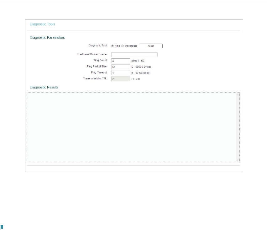
105
Chapter 6 Configure the Router in Range Extender Mode
• Diagnostic Tool - Select one diagnostic tool.
• Ping - This diagnostic tool troubleshoots connectivity, reachability, and name
resolution to a given host or gateway.
• Tracerouter - This diagnostic tool tests the performance of a connection.
Note:
You can use ping/traceroute to test both numeric IP address or domain name. If pinging/tracerouting the IP address is
successful, but pinging/tracerouting the domain name is not, you might have a name resolution problem. In this case,
ensure that the domain name you are specifying can be resolved by using Domain Name System (DNS) queries.
• IP Address/Domain Name - Enter the destination IP address (such as 192.168.0.1) or
Domain name (such as www.tp-link.com).
• Pings Count - The number of Ping packets for a Ping connection.
• Ping Packet Size - The size of Ping packet.
• Ping Timeout - Set the waiting time for the reply of each Ping packet. If there is no
reply in the specified time, the connection is overtime.
• Traceroute Max TTL - The max number of hops for a Traceroute connection.
3. Click Start to check the connectivity of the internet.
4. The Diagnostic Results page displays the diagnosis result. If the result is similar to
the following figure, the connectivity of the internet is fine.

106
Chapter 6 Configure the Router in Range Extender Mode
Note: Only one user can use this tool at one time. Options “Number of Pings”, “Ping Size” and “Ping Timeout” are used
for the Ping function. Option “Tracert Hops” is used for the Tracert function.
6. 8. 4. Firmware Upgrade
TP-Link is dedicated to improving and richening the product features, giving users
a better network experience. We will release the latest firmware at TP-Link official
website. You can download the latest firmware file from the Support page of our website
www.tp-link.com and upgrade the firmware to the latest version.
1. Download the latest firmware file for the router from our website www.tp-link.com.
2. Visit http://tplinkwifi.net, and log in with the username and password you set for the
router.
3. Go to System Tools > Firmware Upgrade.
4. Click Choose File to locate the downloaded firmware file, and click Upgrade.
6. 8. 5. Factory Defaults
1. Visit http://tplinkwifi.net, and log in with the username and password you set for the
router.
2. Go to System Tools > Factory Defaults. Click Restore to reset all settings to the
default values.
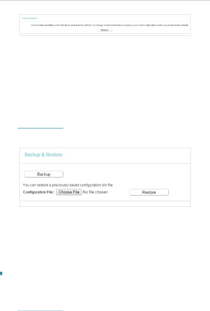
107
Chapter 6 Configure the Router in Range Extender Mode
• The default Username: admin
• The default
Password: admin
• The default
IP Address: 192.168.0.1
• The default
Subnet Mask: 255.255.255.0
6. 8. 6. Backup & Restore
The configuration settings are stored as a configuration file in the router. You can
backup the configuration file in your computer for future use and restore the router to
the previous settings from the backup file when needed.
1. Visit http://tplinkwifi.net, and log in with the username and password you set for the
router.
2. Go to System Tools > Backup & Restore.
¾To backup configuration settings:
Click Backup to save a copy of the current settings in your local computer. A “.bin“ file
of the current settings will be stored in your computer.
¾To restore configuration settings:
1. Click Choose File to locate the backup configuration file stored in your computer, and
click Restore.
2. Wait a few minutes for the restoring and rebooting.
Note:
During the restoring process, do not power off or reset the router.
6. 8. 7. Reboot
1. Visit http://tplinkwifi.net, and log in with the username and password you set for the
router.
2. Go to System Tools > Reboot, and you can restart your router.
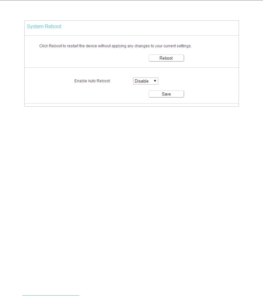
108
Chapter 6 Configure the Router in Range Extender Mode
3. Enable the auto reboot function as needed.
• Disable - Disable the auto reboot function.
• Timeout - Specify a time period(1-72 hours), then the router will reboot
automatically after every this interval.
• Schedule - The router will reboot automatically according to a specific time
schedule.
Some settings of the router will take effect only after rebooting, including:
• Change the LAN IP Address (system will reboot automatically).
• Change the DHCP Settings.
• Change the Working Modes.
• Change the Web Management Port.
• Upgrade the firmware of the router (system will reboot automatically).
• Restore the router to its factory defaults (system will reboot automatically).
• Update the configuration with the file (system will reboot automatically).
6. 8. 8. Administrator
1. Visit http://tplinkwifi.net, and log in with the username and password you set for the
router.
2. Go to System Tools > Administrator, and you can change the factory default username
and password of the router, and manage your router from a remote location via the
internet.
¾To view and change the account settings:

109
Chapter 6 Configure the Router in Range Extender Mode
It is strongly recommended that you change the default username and password of the
router, for all users that try to access the router’s web mangement page or Quick Setup
will be prompted for the router’s username and password.
Note:
The new username and password must not exceed 15 characters and not include any spacing.
¾To manage your Router from a remote location via the internet:
1. Specify the remote management web port number and click Save.
• Web Management Port - The default remote management web port number is
80. For greater security, you can change the remote management web port to
a number between 1024 and 65535 but do not use the number of any common
service port.
• Remote Management IP Address - This is the current address you will use when
accessing your router from the internet. This function is disabled when the IP
address is set to the default value of 0.0.0.0. To enable this function change
0.0.0.0 to a valid IP address. If set to 255.255.255.255, then all the hosts can
access the router from internet.
• Certificate - A file that provides you with authentication information. Download
and install the certificate for Local/Remote Management via HTTPS if you need
it. Once the certificate is installed, warnings will not pop up when you access
the router via HTTPS.

110
Chapter 6 Configure the Router in Range Extender Mode
2. Enter your router’s WAN IP address into your browser’s address bar, followed by a
colon and the custom port number you set in the Web Management Port box. For
example, if your Router’s WAN address is 202.96.12.8 and you use port number 8080,
enter http://202.96.12.8:8080 in your browser.
3. Enter the router’s password to access the web mangement page remotely.
Note:
• Be sure to change the router’s default password to a secure password.
• If the web management port conflicts with the one used for a Virtual Server entry, the entry will be
automatically disabled after the setting is saved.
6. 8. 9. System Log
1. Visit http://tplinkwifi.net, and log in with the username and password you set for the
router.
2. Go to System Tools > System Log, and you can view the logs of the router.
• Loge Type -By selecting the log type, only logs of this type will be shown.
• Log Level - By selecting the log level, only logs of this level will be shown.
• Refresh - Refresh the page to show the latest log list.
• Clear Log - All the logs will be deleted from the router permanently, not just from the
page.
6. 9. Log Out
Click Logout at the bottom of the main menu, and you will log out of the web page and
be directed to the login window.

111
FAQ
Q1. What should I do if I forget my wireless password?
The default wireless password is printed on the label of the router. If the password has
been altered, please connect your computer to the router using an Ethernet cable and
follow the steps below:
1. Visit http://tplinkwifi.net, and log in with the username and password you set for the
router.
2. Go to Wireless > Wireless Security to retrieve or reset your wireless password.
Q2. What should I do if I forget my login password of the web management
page?
The default username and password of the web management page are admin (in
lowercase).
If you have altered the username and password but Password Recovery is disabled:
1. Reset the router to factory default settings: press and hold the Reset button until all
LEDs turn off and then release the button;
2. Visit http://tplinkwifi.net, and enter admin (in lowercase) as both username and
password to log in.
Note: You’ll need to reconfigure the router to surf the internet once the router is reset, and please mark down your new
password for future use.
Q3. What should I do if I cannot log in to the router’s web management
page?
1. This can happen for a variety of reasons. Please try the methods below to log in again.
• Make sure your computerthe has connected to the router correctly and the
corresponding LED light up.
• Make sure the IP address of your computer is configured as Obtain an IP address
automatically and Obtain DNS server address automatically.
2. Make sure you enter the correct IP address to log in: http://tplinkwifi.net.
• Check your computer’s settings:
3. Go to Start > Control Panel > Network and Internet, and click View network status
and tasks.
1 ) Click Internet Options on the bottom left.
2 ) Click Connections and select Never dial a connection.
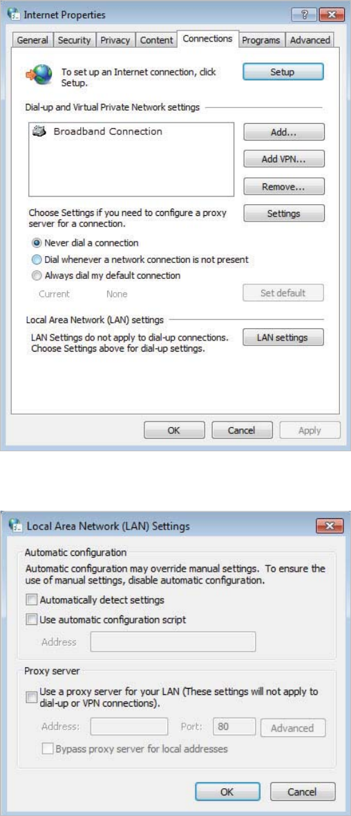
112
3 ) Click LAN settings and deselect the following three options, and click OK.
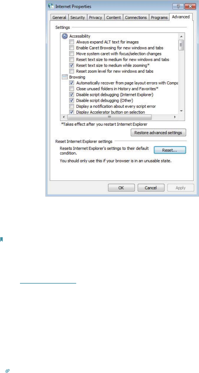
113
4 ) Go to Advanced > Restore advanced settings, and click OK to save the settings.
• Use another web browser or computer to log in again.
• Reset the router to factory default settings and try again. If the login still fails, please
contact the technical support.
Note: You’ll need to reconfigure the router to surf the internet once the router is reset.
Q4. What should I do if I cannot access the internet even though the
configuration is finished?
1. Visit http://tplinkwifi.net, and log in to with the username and password you set for
the router.
2. Go to Status to check WAN status:
If IP Address is a valid one, please try the methods below and try again:
• Your computer might not recognize any DNS server addresses, please manually
configure DNS server.
1 ) Go to DHCP.
2 ) Enter 8.8.8.8 as Primary DNS, and click Save.
Tips: 8.8.8.8 is a safe and public DNS server operated by Google.
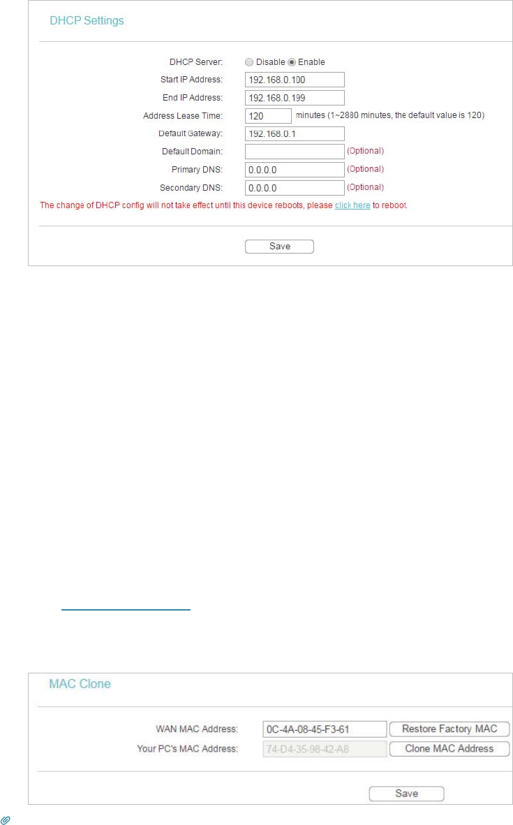
114
• Restart the modem and the router.
1 ) Power off your modem and the router, and leave them off for 1 minute.
2 ) Power on your modem first, and wait about 2 minutes.
3 ) Power on the router, and wait another 1 or 2 minutes and check the internet
access.
• Reset the router to factory default settings and reconfigure the router.
• Upgrade the firmware of the router.
• Check the TCP/IP settings on the particular device if all other devices can get internet
from the router.
If the IP Address is 0.0.0.0, please try the methods below and try again:
• Make sure the physical connection between the router and the modem is proper.
• Clone the MAC address of your computer.
1 ) Visit http://tplinkwifi.net, and log in with the username and password you set for
the router.
2 ) Go to Network > MAC Clone, select Clone MAC Address and click Save.
Tips:
• Some ISP will register the MAC address of your computer when you access the internet for the first time
through their Cable modem, if you add a router into your network to share your internet connection, the ISP will
not accept it as the MAC address is changed, so we need to clone your computer’s MAC address to the router.
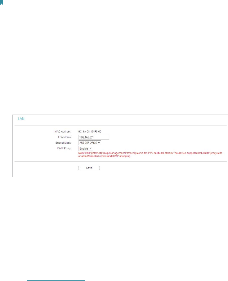
115
• The MAC addresses of a computer in wired connection and wireless connection are different.
• Modify the LAN IP address of the router.
Note:
Most TP-Link routers use 192.168.0.1/192.168.1.1 as their default LAN IP address, it may conflict with the IP range
of your existent ADSL modem/router. If so, the router is not able to communicate with your modem and cause you
can’t access the internet. To resolve this problem, we need to change the LAN IP address of the router to avoid
such conflict, for example, 192.168.2.1.
1 ) Visit http://tplinkwifi.net, and log in with the username and password you set for
the router.
2 ) Go to Network > LAN.
3 ) Modify the LAN IP address as the follow picture shows. Here we take 192.168.2.1
as an example.
4 ) Click Save.
• Restart the modem and the router.
1 ) Power off your modem and the router, and leave them off for 1 minute.
2 ) Power on your modem first, and wait about 2 minutes.
3 ) Power on the router, and wait another 1 or 2 minutes and check the internet
access.
• Double check the internet Connection Type.
1 ) Confirm your internet Connection Type, which can be learned from the ISP.
2 ) Visit http://tplinkwifi.net, and log in with the username and password you set for
the router.
3 ) Go to Network > WAN.
4 ) Select your WAN Connection Type and fill in other parameters.
5 ) Click Save.
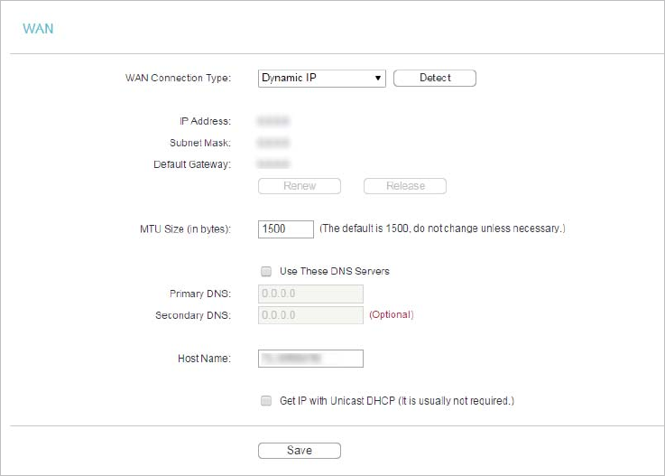
116
6 ) Restart the modem and the router.
• Please upgrade the firmware of the router.
If you’ve tried every method above but cannot access the internet, please contact the
technical support.
Q5. What should I do if I cannot find my wireless network or I cannot
connect the wireless network?
If you fail to find any wireless network, please follow the steps below:
• Make sure the wireless function of your device is enabled if you’re using a laptop
with a built-in wireless adapter. You can refer to the relevant document or contact the
laptop manufacturer.
• Make sure the wireless adapter driver is installed successfully and the wireless
adapter is enabled.
• On Windows 7
1 ) If you see the message No connections are available, it is usually because the
wireless function is disabled or blocked somehow.
2 ) Clicking Troubleshoot and windows might be able to fix the problem by itself.
• On Windows XP
1 ) If you see the message Windows cannot configure this wireless connection,
this is usually because windows configuration utility is disabled or you are
running another wireless configuration tool to connect the wireless.
2 ) Exit the wireless configuration tool (the TP-Link Utility, for example).
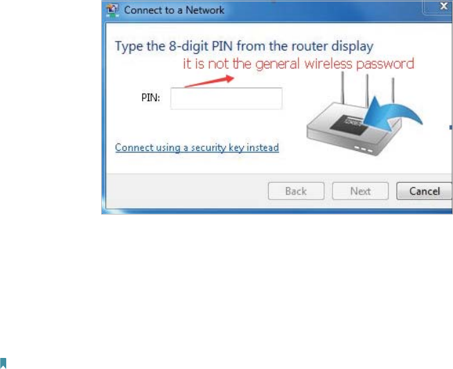
117
3 ) Select and right click My Computer on Desktop, and select Manage to open
Computer Management window.
4 ) Expand Services and Applications > Services, and find and locate Wireless
Zero Configuration in the Services list on the right side.
5 ) Right click Wireless Zero Configuration, and then select Properties.
6 ) Change Startup type to Automatic, click Start and make sure the Service status
is Started. And then click OK.
If you can find other wireless network except your own, please follow the steps below:
• Check the WLAN LED indicator on your wireless router/modem.
• Make sure your computer/device is still in the range of your router/modem. Move
closer if it is currently too far away.
If you can find your wireless network but fail to connect, please follow the steps below:
• Authenticating problem/password mismatch:
1 ) Sometimes you will be asked to type in a PIN number when you connect to
the wireless network for the first time. This PIN number is different from the
Wireless Password/Network Security Key. Usually you can only find it on the
label of your router.
2 ) If you cannot find the PIN or PIN failed, you may choose Connecting using a
security key instead, and then type in the Wireless Password/Network Security
Key.
3 ) If it continues to show note of Network Security Key Mismatch, it is suggested
to confirm the wireless password of your wireless router.
Note: Wireless Password/Network Security Key is case sensitive.
• Windows unable to connect to XXXX / Can not join this network / Taking longer than
usual to connect to this network:
• Check the wireless signal strength of your network, if it is weak (1~3 bars),
please move the router closer and try again.
118
• Change the wireless Channel of the router to 1,6,or 11 to reduce interference
from other networks.
• Re-install or update the driver for your wireless adapter of the computer.

119
COPYRIGHT & TRADEMARKS
Specifications are subject to change without notice. is a registered trademark
of TP-Link Technologies Co., Ltd. Other brands and product names are trademarks or
registered trademarks of their respective holders.
No part of the specifications may be reproduced in any form or by any means or used
to make any derivative such as translation, transformation, or adaptation without
permission from TP-Link Technologies Co., Ltd. Copyright © 2018 TP-Link Technologies
Co., Ltd. All rights reserved.

120
FCC compliance information statement
Product Name: AC750 Wireless Dual Band Router
Model Number: Archer C20
Component Name Model
I.T.E POWER SUPPLY T120100-2B1
Responsible party:
TP-Link USA Corporation, d/b/a TP-Link North America, Inc.
Address: 145 South State College Blvd. Suite 400, Brea, CA 92821
Website: http://www.tp-link.com/us/
Tel: +1 626 333 0234
Fax: +1 909 527 6803
E-mail: sales.usa@tp-link.com
This equipment has been tested and found to comply with the limits for a Class B digital
device, pursuant to part 15 of the FCC Rules. These limits are designed to provide
reasonable protection against harmful interference in a residential installation. This
equipment generates, uses and can radiate radio frequency energy and, if not installed
and used in accordance with the instructions, may cause harmful interference to radio
communications. However, there is no guarantee that interference will not occur in a
particular installation. If this equipment does cause harmful interference to radio or
television reception, which can be determined by turning the equipment off and on, the
user is encouraged to try to correct the interference by one or more of the following
measures:
• Reorient or relocate the receiving antenna.
• Increase the separation between the equipment and receiver.
• Connect the equipment into an outlet on a circuit different from that to which the
receiver is connected.
• Consult the dealer or an experienced radio/ TV technician for help.
This device complies with part 15 of the FCC Rules. Operation is subject to the following
two conditions:
1. This device may not cause harmful interference.
2. This device must accept any interference received, including interference that may
cause undesired operation.
Any changes or modifications not expressly approved by the party responsible for
compliance could void the user’s authority to operate the equipment.

121
Note: The manufacturer is not responsible for any radio or TV interference caused by
unauthorized modifications to this equipment. Such modifications could void the user’s
authority to operate the equipment.
FCC RF Radiation Exposure Statement
This equipment complies with FCC RF radiation exposure limits set forth for an
uncontrolled environment. This device and its antenna must not be co-located or
operating in conjunction with any other antenna or transmitter.
“To comply with FCC RF exposure compliance requirements, this grant is applicable to
only Mobile Configurations. The antennas used for this transmitter must be installed to
provide a separation distance of at least 20 cm from all persons and must not be co-
located or operating in conjunction with any other antenna or transmitter.”
We, TP-Link USA Corporation, has determined that the equipment shown as above
has been shown to comply with the applicable technical standards, FCC part 15. There
is no unauthorized change is made in the equipment and the equipment is properly
maintained and operated.
Issue Date: 2018.5.30
FCC compliance information statement
Product Name: I.T.E POWER SUPPLY
Model Number: T120100-2B1
Responsible party:
TP-Link USA Corporation, d/b/a TP-Link North America, Inc.
Address: 145 South State College Blvd. Suite 400, Brea, CA 92821
Website: http://www.tp-link.com/us/
Tel: +1 626 333 0234
Fax: +1 909 527 6803
E-mail: sales.usa@tp-link.com
This equipment has been tested and found to comply with the limits for a Class B digital
device, pursuant to part 15 of the FCC Rules. These limits are designed to provide
reasonable protection against harmful interference in a residential installation. This
equipment generates, uses and can radiate radio frequency energy and, if not installed
and used in accordance with the instructions, may cause harmful interference to radio
communications. However, there is no guarantee that interference will not occur in a
particular installation. If this equipment does cause harmful interference to radio or
television reception, which can be determined by turning the equipment off and on, the
122
user is encouraged to try to correct the interference by one or more of the following
measures:
• Reorient or relocate the receiving antenna.
• Increase the separation between the equipment and receiver.
• Connect the equipment into an outlet on a circuit different from that to which the
receiver is connected.
• Consult the dealer or an experienced radio/ TV technician for help.
This device complies with part 15 of the FCC Rules. Operation is subject to the following
two conditions:
1. This device may not cause harmful interference.
2. This device must accept any interference received, including interference that may
cause undesired operation.
Any changes or modifications not expressly approved by the party responsible for
compliance could void the user’s authority to operate the equipment.
We, TP-Link USA Corporation, has determined that the equipment shown as above
has been shown to comply with the applicable technical standards, FCC part 15. There
is no unauthorized change is made in the equipment and the equipment is properly
maintained and operated.
Issue Date: 2018.5.30

123
CE Mark Warning
This is a class B product. In a domestic environment, this product may cause radio
interference, in which case the user may be required to take adequate measures.
OPERATING FREQUENCY(the maximum transmitted power)
2400 MHz -2483.5 MHz(20dBm)
5150 MHz -5250 MHz(23dBm)
EU declaration of conformity
TP-Link hereby declares that the device is in compliance with the essential requirements
and other relevant provisions of directives 2014/53/EU and 2011/65/EU.
The original EU declaration of conformity may be found at http://www.tp-link.com/en/ce.
RF Exposure Information
This device meets the EU requirements (2014/53/EU Article 3.1a) on the limitation of
exposure of the general public to electromagnetic fields by way of health protection.
The device complies with RF specifications when the device used at 20 cm from your
body.
National restrictions
Restricted to indoor use.
Canadian Compliance Statement
This device complies with Industry Canada license-exempt RSSs. Operation is subject
to the following two conditions:
1 ) This device may not cause interference, and
2 ) This device must accept any interference, including interference that may cause
undesired operation of the device.
Le présent appareil est conforme aux CNR d’Industrie Canada applicables aux appareils
radio exempts de licence. L’exploitation est autorisée aux deux conditions suivantes :
1 ) l’appareil ne doit pas produire de brouillage;
2 ) l’utilisateur de l’appareil doit accepter tout brouillage radioélectrique subi, meme si
le brouillage est susceptible d’en compromettre le fonctionnement.
Caution:
1 ) The device for operation in the band 5150–5250 MHz is only for indoor use to reduce
the potential for harmful interference to co-channel mobile satellite systems;
124
2 ) For devices with detachable antenna(s), the maximum antenna gain permitted for
devices in the bands 5250-5350 MHz and 5470-5725 MHz shall be such that the
equipment still complies with the e.i.r.p. limit;
3 ) For devices with detachable antenna(s), the maximum antenna gain permitted for
devices in the band 5725-5850 MHz shall be such that the equipment still complies
with the e.i.r.p. limits specified for point-to-point and non-point-to-point operation
as appropriate; and
The high-power radars are allocated as primary users (i.e. priority users) of the bands
5250-5350 MHz and 5650-5850 MHz and that these radars could cause interference
and/or damage to LE-LAN devices.
DFS (Dynamic Frequency Selection) products that operate in the bands 5250- 5350
MHz, 5470-5600MHz, and 5650-5725MHz.
Avertissement:
1 ) Le dispositif fonctionnant dans la bande 5150-5250 MHz est réservé uniquement
pour une utilisation à l’intérieur afin de réduire les risques de brouillage préjudiciable
aux systèmes de satellites mobiles utilisant les mêmes canaux;
2 ) Le gain maximal d’antenne permis pour les dispositifs avec antenne(s) amovible(s)
utilisant les bandes 5250-5350 MHz et 5470-5725 MHz doit se conformer à la
limitation P.I.R.E.;
3 ) Le gain maximal d’antenne permis pour les dispositifs avec antenne(s) amovible(s)
utilisant la bande 5725-5850 MHz doit se conformer à la limitation P.I.R.E spécifiée
pour l’exploitation point à point et non point à point, selon le cas.
En outre, les utilisateurs devraient aussi être avisés que les utilisateurs de radars de
haute puissance sont désignés utilisateurs principaux (c.-à-d., qu’ils ont la priorité) pour
les bandes 5250-5350 MHz et 5650-5850 MHz et que ces radars pourraient causer du
brouillage et/ou des dommages aux dispositifs LAN-EL.
Les produits utilisant la technique d’atténuation DFS (sélection dynamique des
fréquences) sur les bandes 5250- 5350 MHz, 5470-5600MHz et 5650-5725MHz.
Radiation Exposure Statement:
This EUT is compliance with SAR for general population/uncontrolled exposure limits
in RSS-102 and had been tested in accordance with the measurement methods and
procedures specified in IEEE 1528 and IEC 62209. This equipment should be installed
and operated with minimum distance 1.0 cm between the radiator and your body. This
device and its antenna(s) must not be co-located or operating in conjunction with any
other antenna or transmitter.

125
Déclaration d’exposition aux radiations:
Cet équipement est conforme aux limites d’exposition aux rayonnements IC établies
pour un environnement non contrôlé. Cet équipement doit être installé et utilisé avec
un minimum de 20 cm de distance entre la source de rayonnement et votre corps.
Industry Canada Statement
CAN ICES-3 (B)/NMB-3(B)
Korea Warning Statements
鲮뼩ꓩꟹ鱉끩끞닆놹볁뿱겕閵鱚ꫦ넩넽넁
NCC Notice
㲐シ炰
ὅ㒂!Ỷ≇䌯暣㲊廣⮬⿏暣㨇䭉䎮彎㱽
䫔⋩Ḵ㡅!䴻✳⺷娵嫱⎰㟤ᷳỶ≇䌯⮬柣暣㨇炻朆䴻姙⎗炻℔⎠ˣ⓮嘇ㆾἧ䓐侭⛯
ᶵ⼿㑭冒嬲㚜柣䌯ˣ≈⣏≇䌯ㆾ嬲㚜⍇姕妰ᷳ䈡⿏ㆾ≇傥ˤ
䫔⋩⚃㡅!Ỷ≇䌯⮬柣暣㨇ᷳἧ䓐ᶵ⼿⼙枧梃凒⬱ℐ⍲⸚㒦⎰㱽忂埴烊䴻䘤䎦㚱⸚
㒦䎦尉㗪炻ㅱ䩳⌛ 䓐炻᷎㓡┬军䃉⸚㒦㗪㕡⼿两临ἧ䓐ˤ⇵枭⎰㱽忂ᾉ炻㊯ὅ
暣ᾉ夷⭂ἄ㤕ᷳ䃉䶂暣ᾉˤỶ≇䌯⮬柣暣㨇暨⽵⍿⎰㱽忂ᾉㆾⶍ㤕ˣ䥹⬠ẍ⍲慓
䗪䓐暣㲊廣⮬⿏暣㨇姕⁁ᷳ⸚㒦ˤ
BSMI Notice
⬱ℐ媖娊⍲㲐シḳ枭
ɀ婳ἧ䓐⍇墅暣㸸ὃㅱ☐ㆾ⎒傥㊱䄏㛔䓊⑩㲐㖶䘬暣㸸栆✳ἧ䓐㛔䓊⑩ˤ
ɀ㶭㻼㛔䓊⑩ᷳ⇵婳⃰㉼㌱暣㸸䶂ˤ婳⊧ἧ䓐㵚橼ˣ☜曏㶭㻼∹ㆾ㽽ⶫ忚埴㶭㻼ˤ
ɀ㲐シ旚㼖炻婳⊧⮯㯜ㆾ℞Ṿ㵚橼㻹㿹⇘㛔䓊⑩ᶲˤ
ɀ㍺㦥冯攳⎋ὃ忂桐ἧ䓐炻ẍ䡢ᾅ㛔䓊⑩䘬㑵ἄ⎗月᷎旚㬊忶䅙炻婳⊧⟝⠆ㆾ央味攳
⎋ˤ
ɀ婳⊧⮯㛔䓊⑩伖㓦㕤月役䅙㸸䘬⛘㕡ˤ昌朆㚱㬋ⷠ䘬忂桐炻⏎⇯ᶵ⎗㓦⛐⭮攱ỵ伖
ᷕˤ
ɀ婳ᶵ天䥩冒ㇻ攳㨇㭤炻ᶵ天▿娎冒埴䵕ᾖ㛔䓊⑩炻婳䓙㌰㪲䘬⮰㤕Ṣ⢓忚埴㬌枭ⶍ
ἄˤ
旸䓐䈑岒⏓㚱ね㱩㧁䣢倚㖶㚠
䓊⑩⃫ẞ
⎵䧙
旸䓐䈑岒⍲℞⊾⬠䫎嘇
戃
Qc
捀
De
㰆!
Ih
ℕ₡戣!
DsWJ
⣂㹜倗劗
QCC
⣂㹜Ḵ劗慂
QCEF
QDC ˕˕˕˕˕ ˕

126
⢾㭤˕˕˕˕˕ ˕
暣㸸怑惵☐ ȹ˕˕˕˕ ˕
⁁侫2/Ⱦ崭↢1/2xu&ȿ⍲Ⱦ崭↢1/12xu&ȿ䲣㊯旸䓐䈑岒ᷳ䘦↮㭼⏓慷崭↢䘦↮㭼⏓慷➢㸾ῤˤ
⁁侫3/!Ⱦ˕ȿ䲣㊯娚枭旸䓐䈑岒ᷳ䘦↮㭼⏓慷㛒崭↢䘦↮㭼⏓慷➢㸾ῤˤ
⁁侫!4/!Ⱦȹȿ!䲣㊯娚枭旸䓐䈑岒䁢㌺昌枭䚖ˤ
Продукт сертифіковано згідно с правилами системи УкрСЕПРО на відповідність
вимогам нормативних документів та вимогам, що передбачені чинними
законодавчими актами України.
Safety Information
• Keep the device away from water, fire, humidity or hot environments.
• Do not attempt to disassemble, repair, or modify the device.
• Do not use damaged charger or USB cable to charge the device.
• Do not use any other chargers than those recommended
• Do not use the device where wireless devices are not allowed.
• Adapter shall be installed near the equipment and shall be easily accessible.
• Use only power supplies which are provided by manufacturer and in the original
packing of this product. If you have any questions, please don’t hesitate to contact us.
Please read and follow the above safety information when operating the device. We
cannot guarantee that no accidents or damage will occur due to improper use of the
device. Please use this product with care and operate at your own risk.
Explanations of the symbols on the product label
Symbol Explanation
DC voltage
Indoor use only
RECYCLING
This product bears the selective sorting symbol for Waste electrical and electronic equipment
(WEEE). This means that this product must be handled pursuant to European directive 2012/19/
EU in order to be recycled or dismantled to minimize its impact on the environment.
User has the choice to give his product to a competent recycling organization or to the retailer
when he buys a new electrical or electronic equipment.