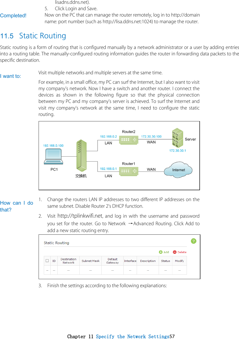
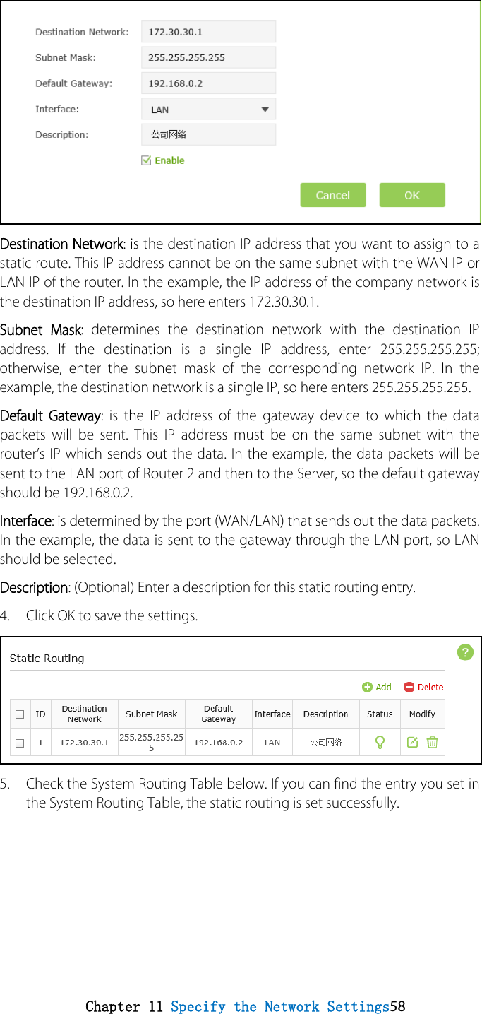
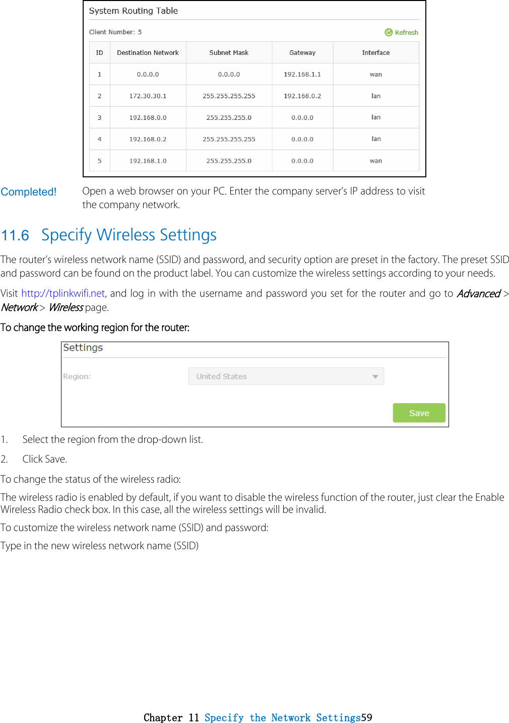
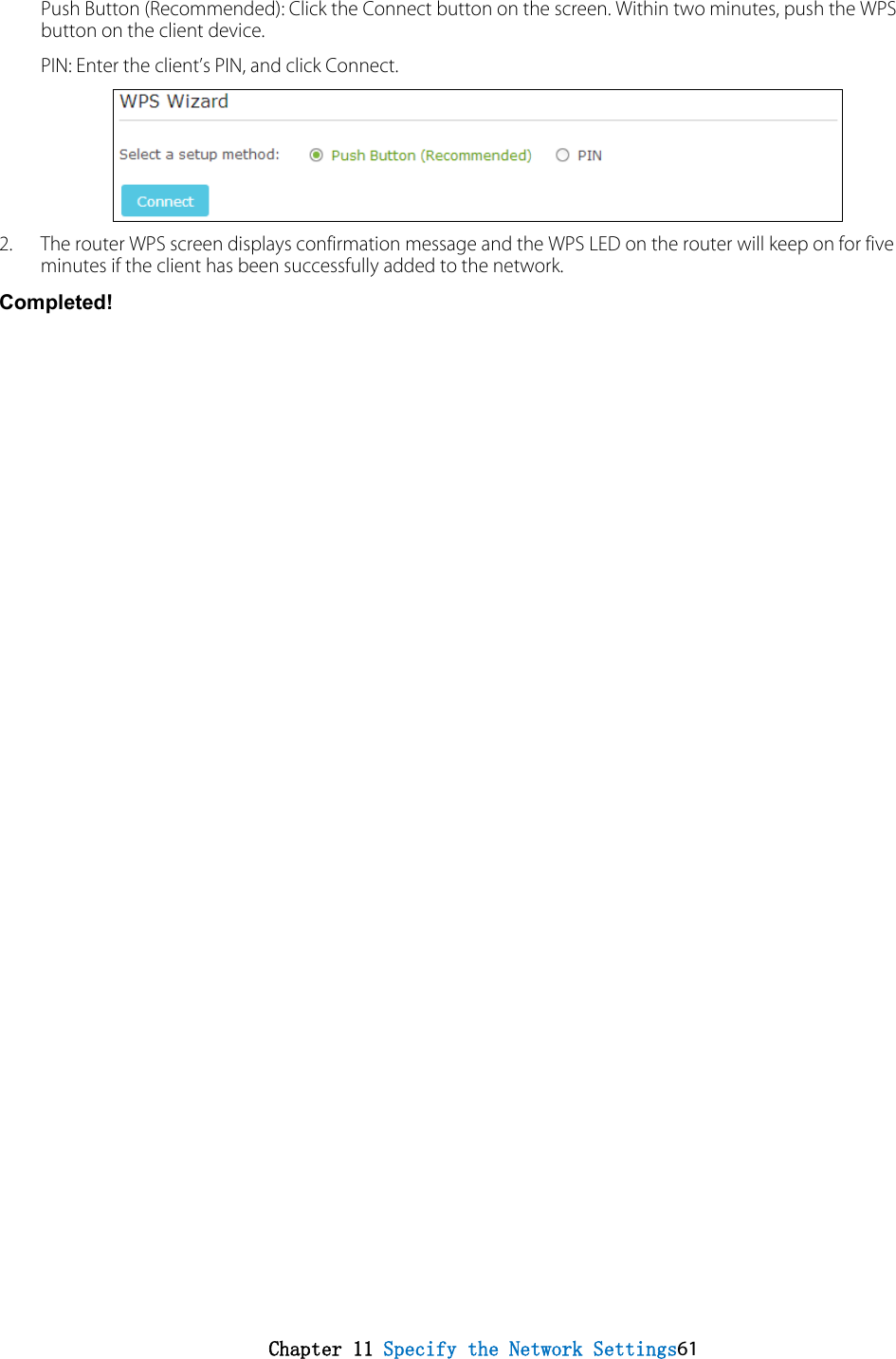
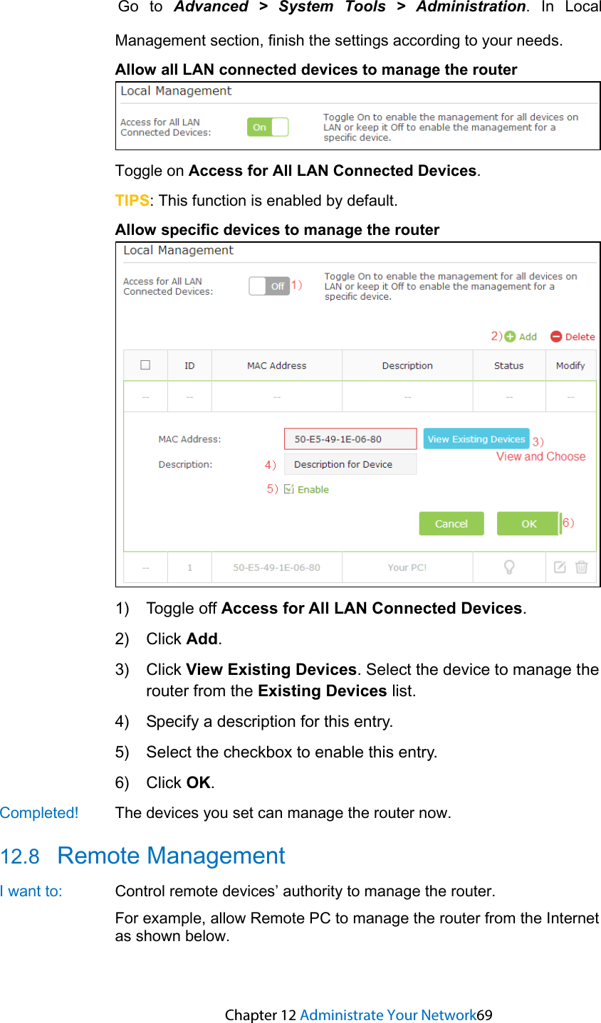
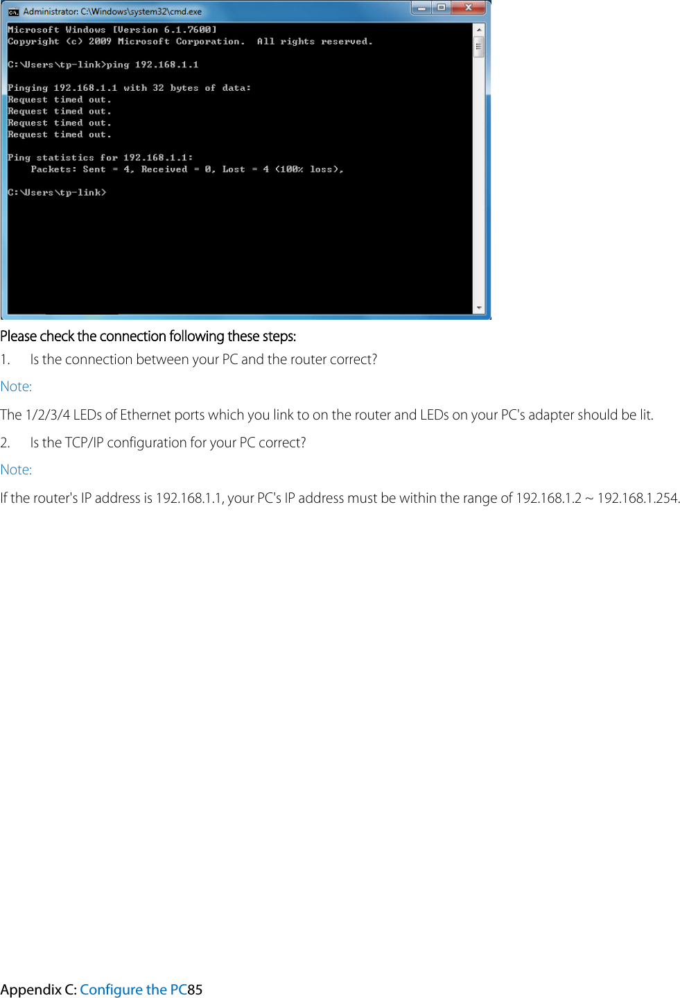
TP Link Technologies C2600 AC2600 Wireless Dual Band Gigabit Router User Manual
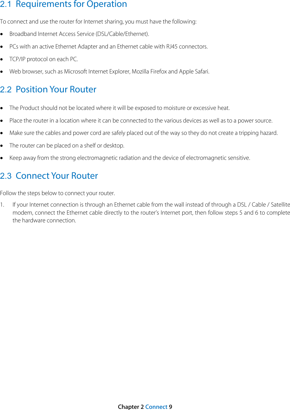
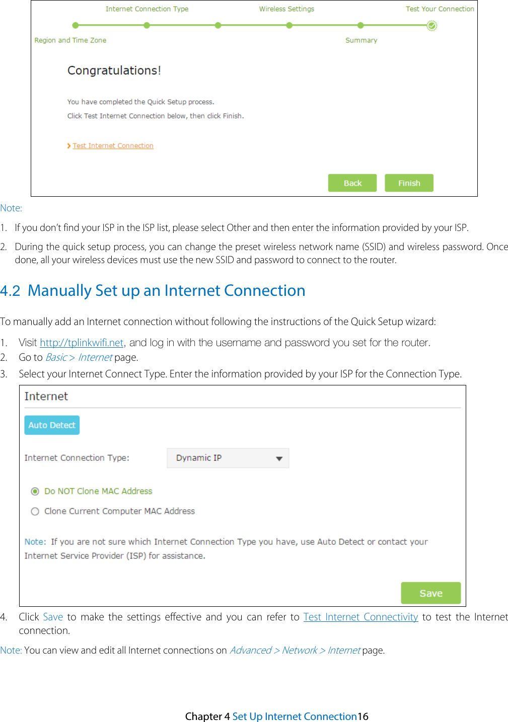
TP-Link Technologies Co., Ltd. AC2600 Wireless Dual Band Gigabit Router
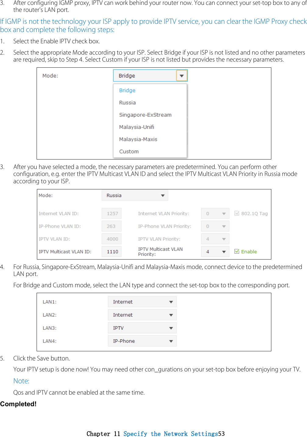
UserManual.wiki
>
TP Link Technologies
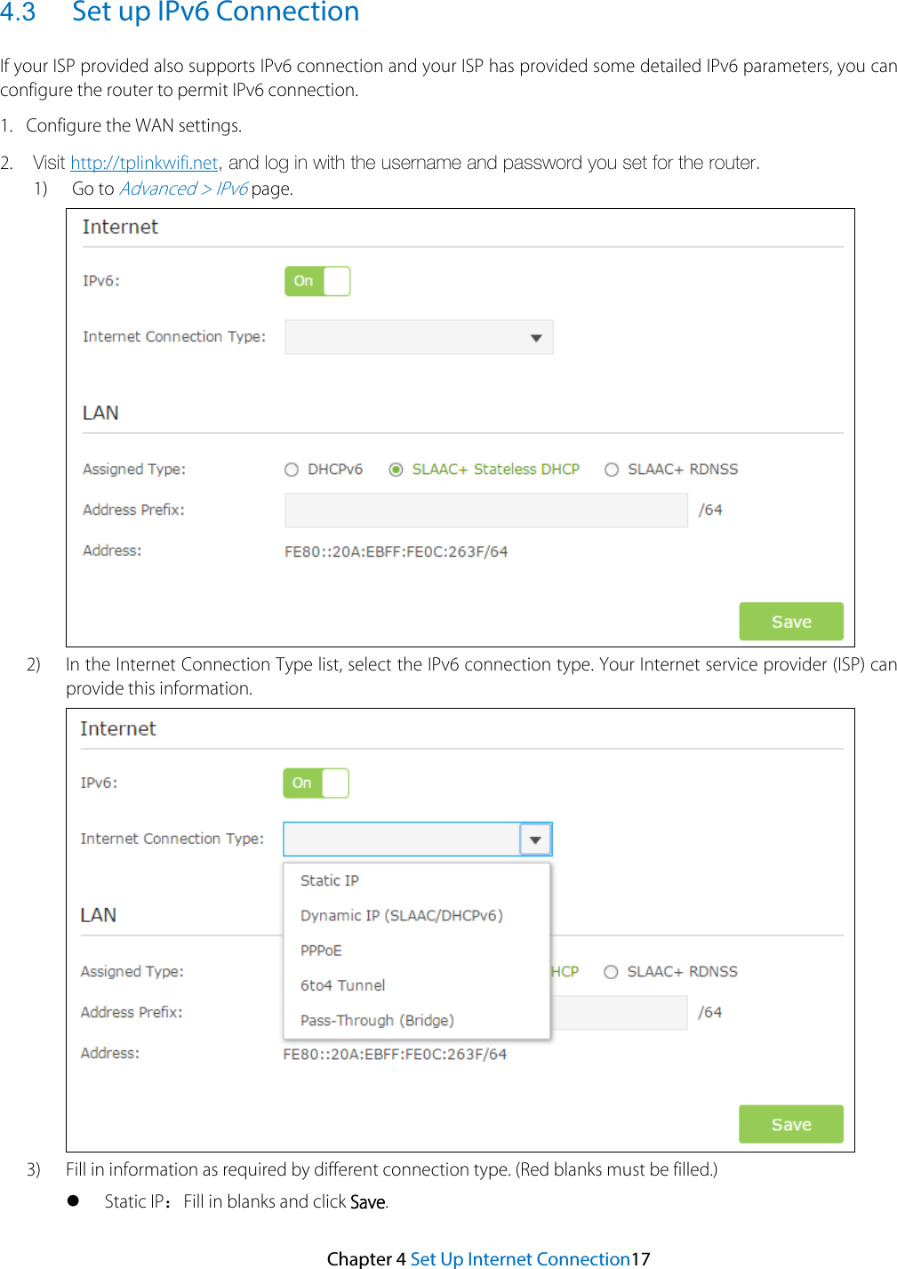
>
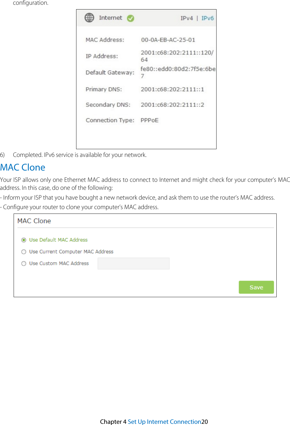
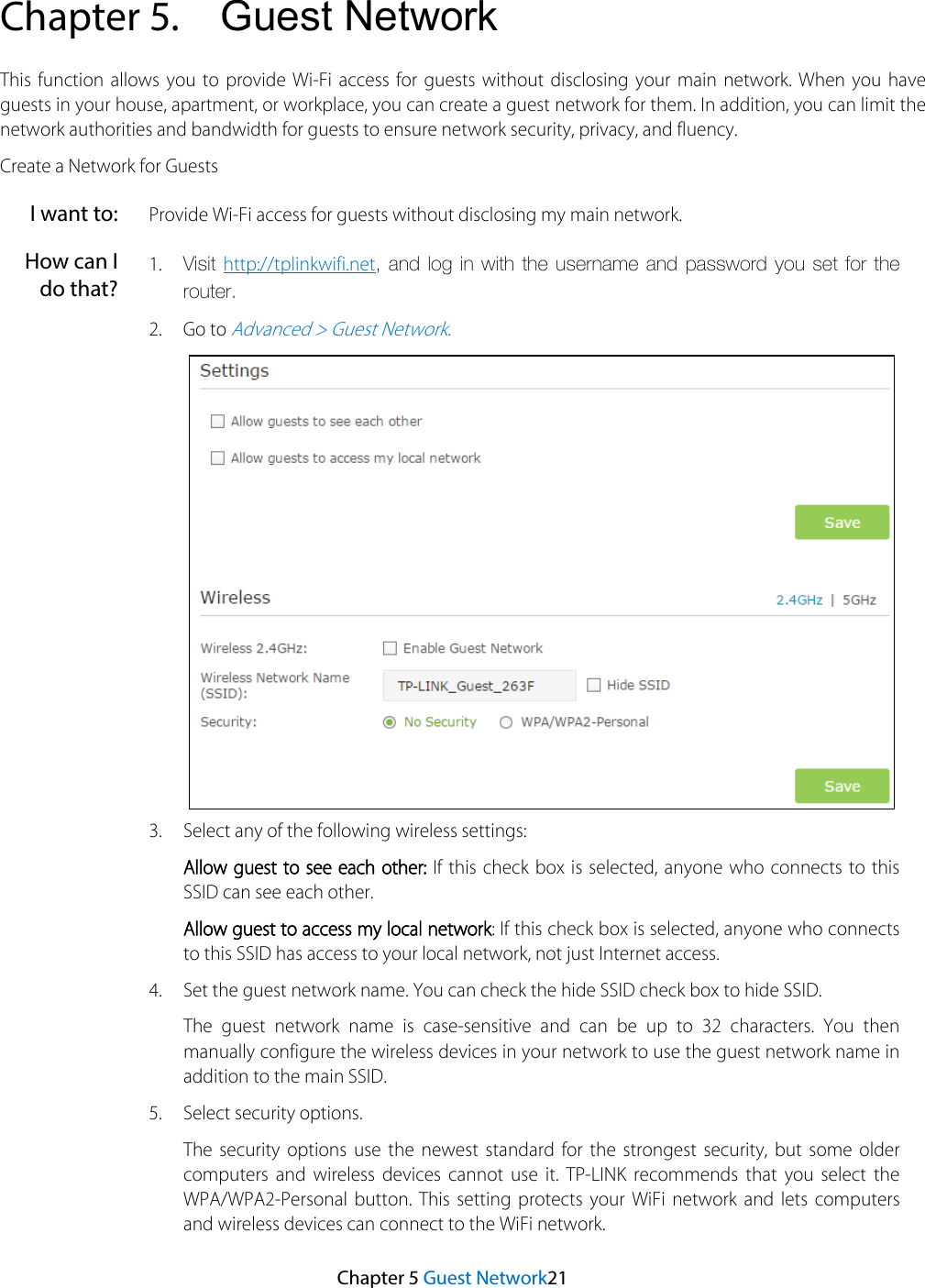
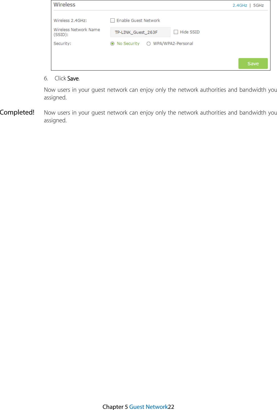
C2600 User Manual
User Manual
Navigation menu
Upload a User Manual
Namespaces
Wiki Guide
HTML
PDF
Info
Views
User Manual
Discussion / Help
Navigation