TP Link Technologies C2V5 AC750 Wireless Dual Band Gigabit Router User Manual for FCC rev2 1

TP-Link Technologies Co., Ltd. AC750 Wireless Dual Band Gigabit Router for FCC rev2 1
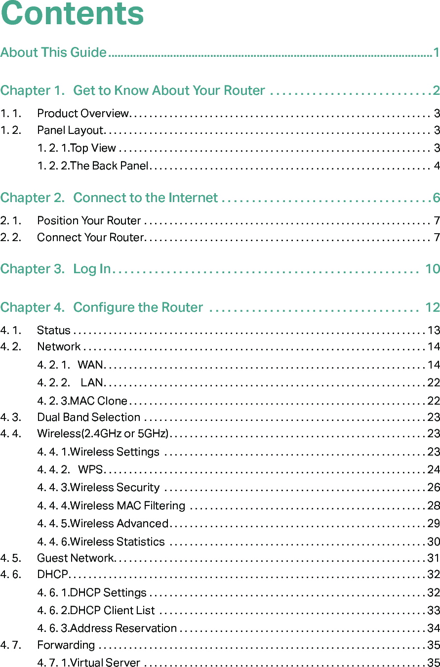
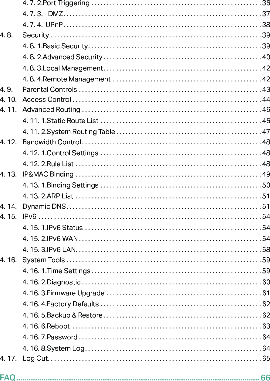
Contents

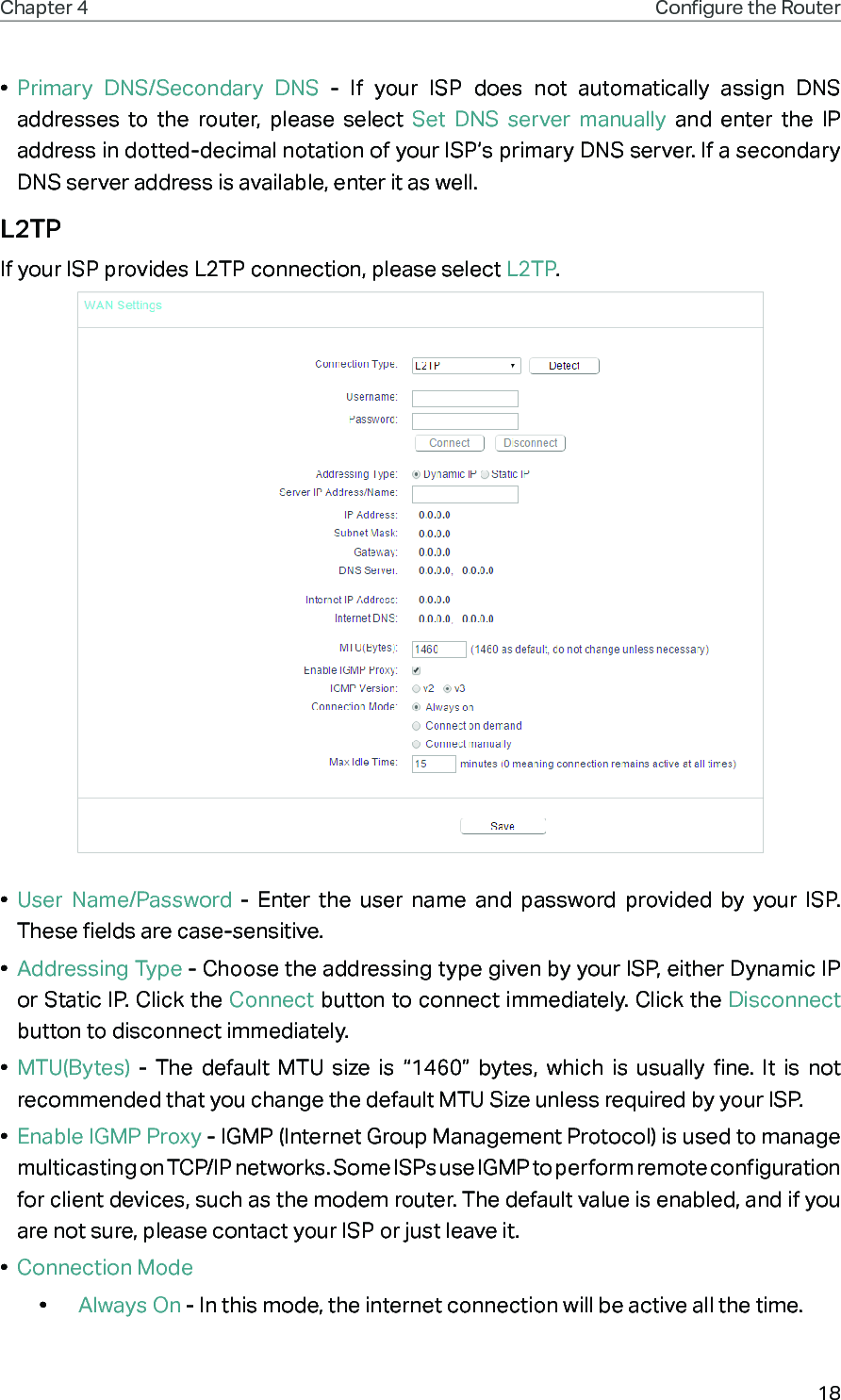
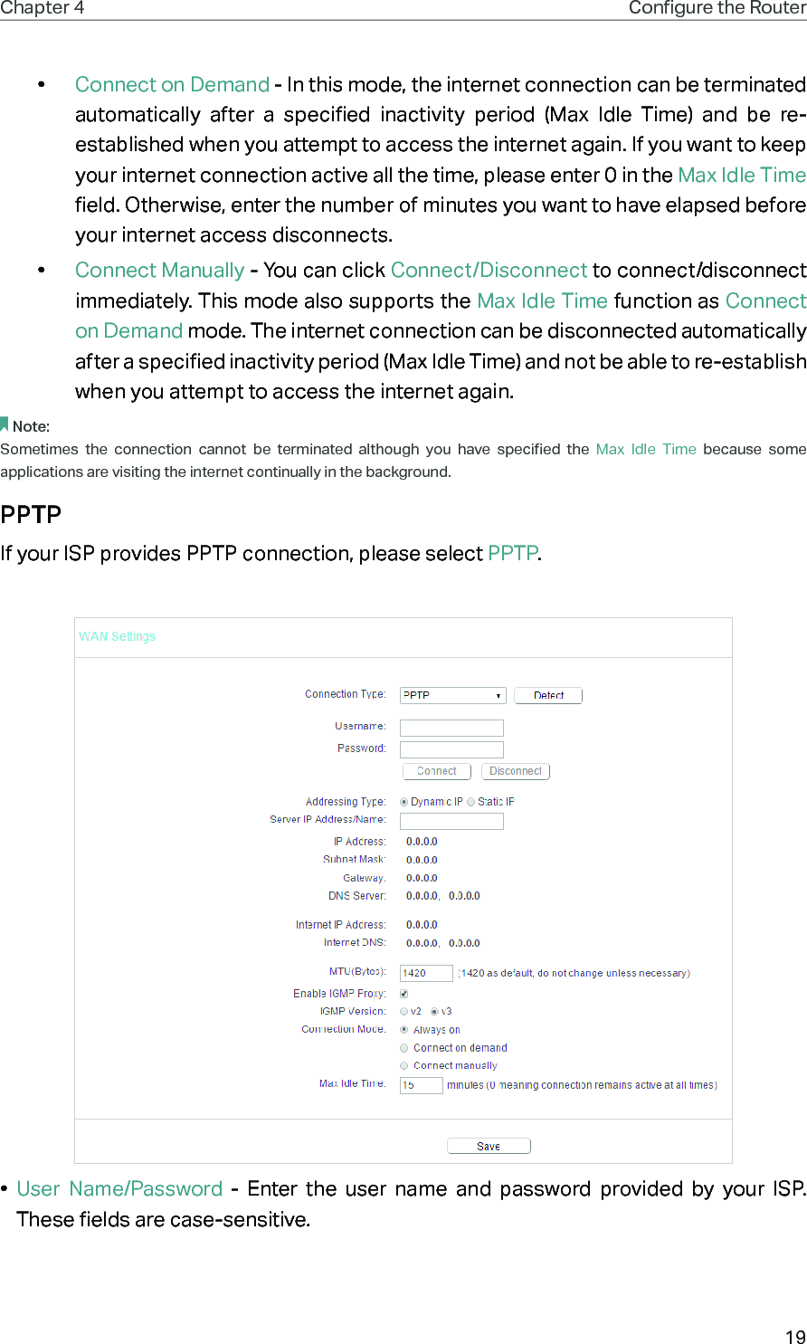
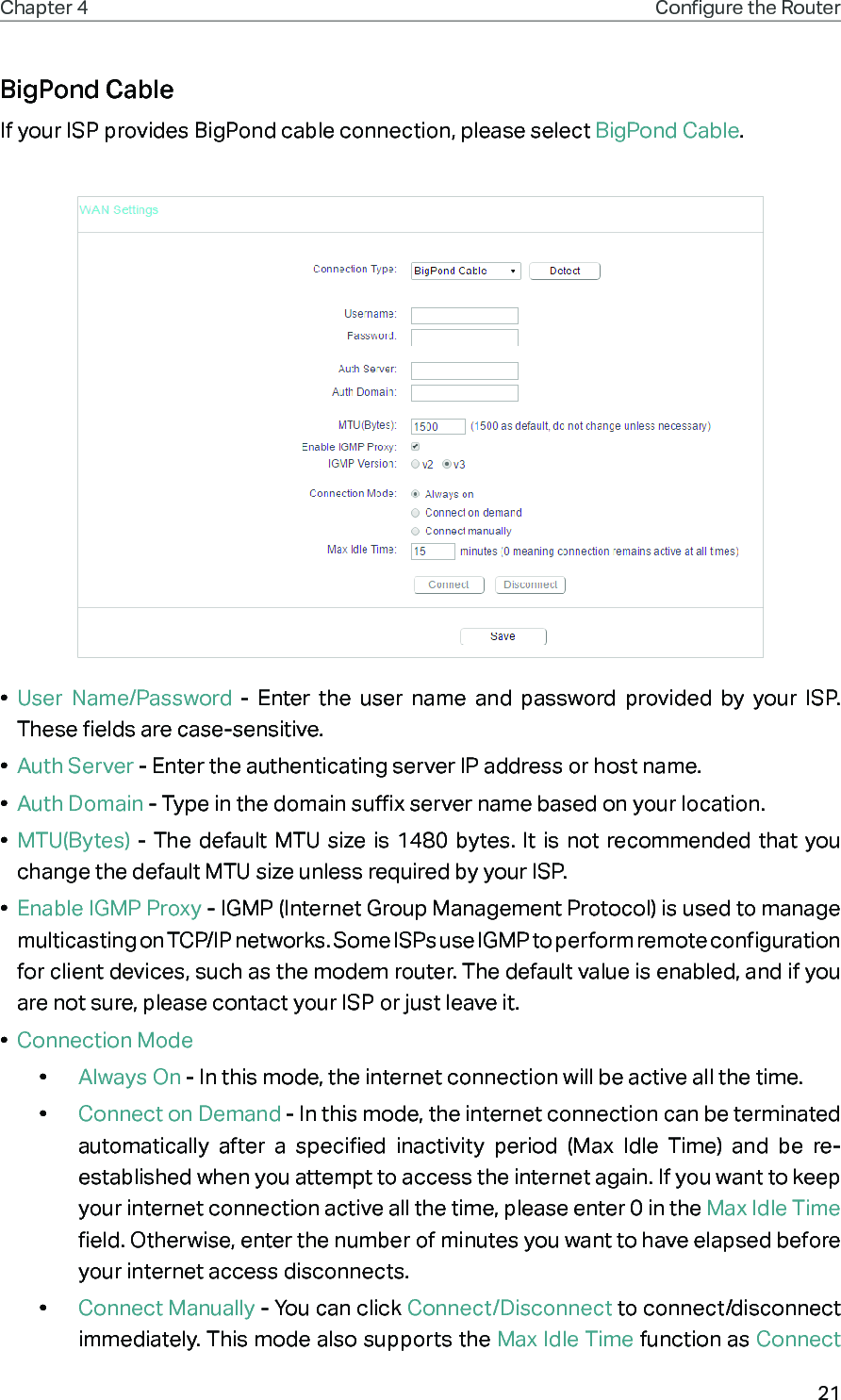
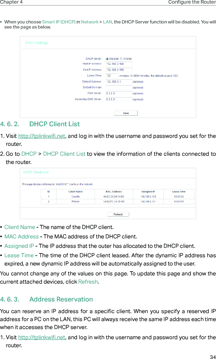
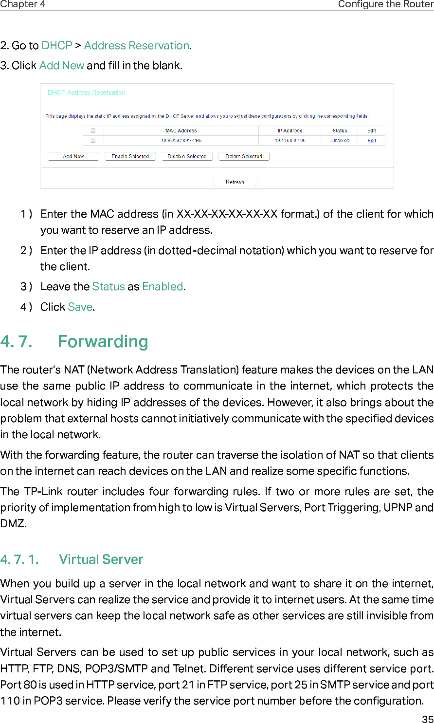
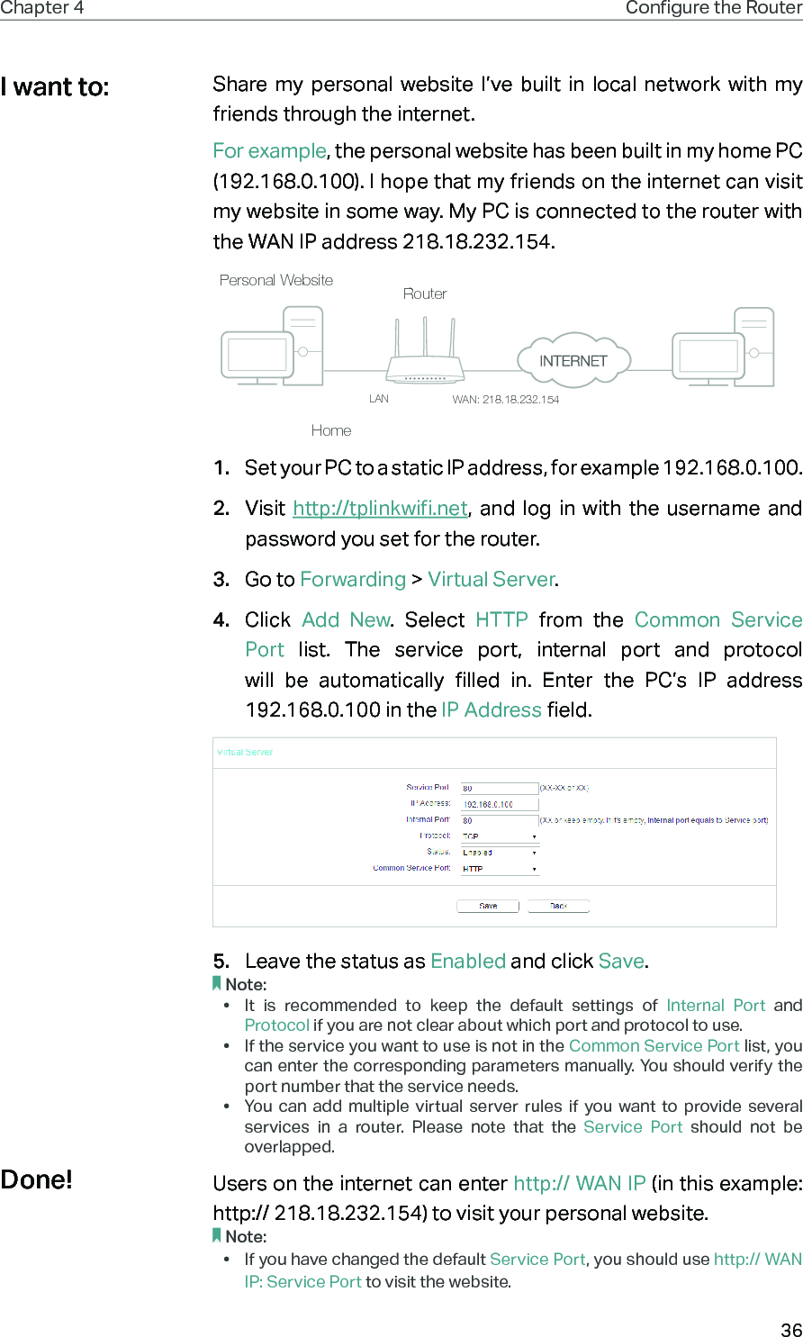
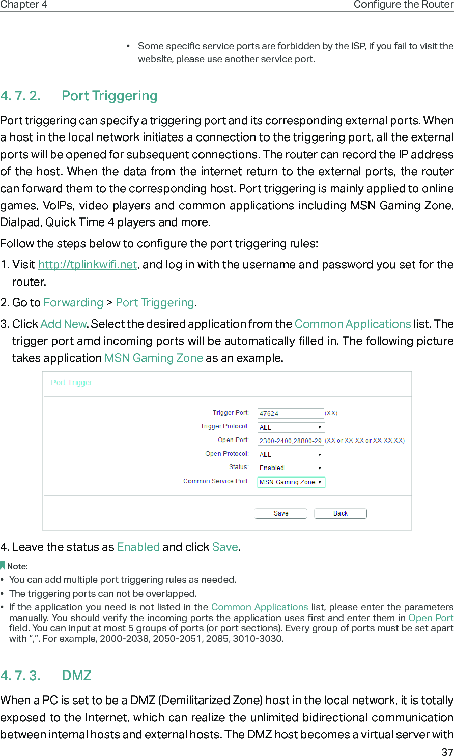
User Manual for FCC_rev2-1

REV5.0.0     1910012133User GuideAC750 Wireless Dual Band Gigabit RouterArcher C2
ContentsAbout This Guide .........................................................................................................1Chapter 1.  Get to Know About Your Router  . . . . . . . . . . . . . . . . . . . . . . . . . . .21. 1.  Product Overview. . . . . . . . . . . . . . . . . . . . . . . . . . . . . . . . . . . . . . . . . . . . . . . . . . . . . . . . . . . . 31. 2.  Panel Layout. . . . . . . . . . . . . . . . . . . . . . . . . . . . . . . . . . . . . . . . . . . . . . . . . . . . . . . . . . . . . . . . . 31. 2. 1. Top View  . . . . . . . . . . . . . . . . . . . . . . . . . . . . . . . . . . . . . . . . . . . . . . . . . . . . . . . . . . . . . . 31. 2. 2. The Back Panel. . . . . . . . . . . . . . . . . . . . . . . . . . . . . . . . . . . . . . . . . . . . . . . . . . . . . . . . 4Chapter 2.  Connect to the Internet  . . . . . . . . . . . . . . . . . . . . . . . . . . . . . . . . . . .62. 1.  Position Your Router  . . . . . . . . . . . . . . . . . . . . . . . . . . . . . . . . . . . . . . . . . . . . . . . . . . . . . . . . . 72. 2.  Connect Your Router. . . . . . . . . . . . . . . . . . . . . . . . . . . . . . . . . . . . . . . . . . . . . . . . . . . . . . . . . 7Chapter 3.  Log In. . . . . . . . . . . . . . . . . . . . . . . . . . . . . . . . . . . . . . . . . . . . . . . . . . .  10Chapter 4.  Configure the Router   . . . . . . . . . . . . . . . . . . . . . . . . . . . . . . . . . . .  124. 1.  Status  . . . . . . . . . . . . . . . . . . . . . . . . . . . . . . . . . . . . . . . . . . . . . . . . . . . . . . . . . . . . . . . . . . . . . . 134. 2.  Network  . . . . . . . . . . . . . . . . . . . . . . . . . . . . . . . . . . . . . . . . . . . . . . . . . . . . . . . . . . . . . . . . . . . . 144. 2. 1.  WAN. . . . . . . . . . . . . . . . . . . . . . . . . . . . . . . . . . . . . . . . . . . . . . . . . . . . . . . . . . . . . . . . 144. 2. 2.  LAN. . . . . . . . . . . . . . . . . . . . . . . . . . . . . . . . . . . . . . . . . . . . . . . . . . . . . . . . . . . . . . . . 224. 2. 3. MAC Clone . . . . . . . . . . . . . . . . . . . . . . . . . . . . . . . . . . . . . . . . . . . . . . . . . . . . . . . . . . . 224. 3.  Dual Band Selection  . . . . . . . . . . . . . . . . . . . . . . . . . . . . . . . . . . . . . . . . . . . . . . . . . . . . . . . . 234. 4.  Wireless(2.4GHz or 5GHz). . . . . . . . . . . . . . . . . . . . . . . . . . . . . . . . . . . . . . . . . . . . . . . . . . . 234. 4. 1. Wireless Settings  . . . . . . . . . . . . . . . . . . . . . . . . . . . . . . . . . . . . . . . . . . . . . . . . . . . . 234. 4. 2.  WPS. . . . . . . . . . . . . . . . . . . . . . . . . . . . . . . . . . . . . . . . . . . . . . . . . . . . . . . . . . . . . . . . 244. 4. 3. Wireless Security  . . . . . . . . . . . . . . . . . . . . . . . . . . . . . . . . . . . . . . . . . . . . . . . . . . . . 264. 4. 4. Wireless MAC Filtering  . . . . . . . . . . . . . . . . . . . . . . . . . . . . . . . . . . . . . . . . . . . . . . . 284. 4. 5. Wireless Advanced. . . . . . . . . . . . . . . . . . . . . . . . . . . . . . . . . . . . . . . . . . . . . . . . . . . 294. 4. 6. Wireless Statistics  . . . . . . . . . . . . . . . . . . . . . . . . . . . . . . . . . . . . . . . . . . . . . . . . . . . 304. 5.  Guest Network. . . . . . . . . . . . . . . . . . . . . . . . . . . . . . . . . . . . . . . . . . . . . . . . . . . . . . . . . . . . . . 314. 6.  DHCP. . . . . . . . . . . . . . . . . . . . . . . . . . . . . . . . . . . . . . . . . . . . . . . . . . . . . . . . . . . . . . . . . . . . . . . 324. 6. 1. DHCP Settings  . . . . . . . . . . . . . . . . . . . . . . . . . . . . . . . . . . . . . . . . . . . . . . . . . . . . . . . 324. 6. 2. DHCP Client List  . . . . . . . . . . . . . . . . . . . . . . . . . . . . . . . . . . . . . . . . . . . . . . . . . . . . . 334. 6. 3. Address Reservation  . . . . . . . . . . . . . . . . . . . . . . . . . . . . . . . . . . . . . . . . . . . . . . . . . 344. 7.  Forwarding  . . . . . . . . . . . . . . . . . . . . . . . . . . . . . . . . . . . . . . . . . . . . . . . . . . . . . . . . . . . . . . . . . 354. 7. 1. Virtual Server  . . . . . . . . . . . . . . . . . . . . . . . . . . . . . . . . . . . . . . . . . . . . . . . . . . . . . . . . 35
4. 7. 2. Port Triggering  . . . . . . . . . . . . . . . . . . . . . . . . . . . . . . . . . . . . . . . . . . . . . . . . . . . . . . . 364. 7. 3.  DMZ. . . . . . . . . . . . . . . . . . . . . . . . . . . . . . . . . . . . . . . . . . . . . . . . . . . . . . . . . . . . . . . . 374. 7. 4.  UPnP. . . . . . . . . . . . . . . . . . . . . . . . . . . . . . . . . . . . . . . . . . . . . . . . . . . . . . . . . . . . . . . . 384. 8.  Security  . . . . . . . . . . . . . . . . . . . . . . . . . . . . . . . . . . . . . . . . . . . . . . . . . . . . . . . . . . . . . . . . . . . . 394. 8. 1. Basic Security. . . . . . . . . . . . . . . . . . . . . . . . . . . . . . . . . . . . . . . . . . . . . . . . . . . . . . . . 394. 8. 2. Advanced Security . . . . . . . . . . . . . . . . . . . . . . . . . . . . . . . . . . . . . . . . . . . . . . . . . . . 404. 8. 3. Local Management. . . . . . . . . . . . . . . . . . . . . . . . . . . . . . . . . . . . . . . . . . . . . . . . . . . 424. 8. 4. Remote Management  . . . . . . . . . . . . . . . . . . . . . . . . . . . . . . . . . . . . . . . . . . . . . . . . 424. 9.  Parental Controls  . . . . . . . . . . . . . . . . . . . . . . . . . . . . . . . . . . . . . . . . . . . . . . . . . . . . . . . . . . . 434. 10.  Access Control  . . . . . . . . . . . . . . . . . . . . . . . . . . . . . . . . . . . . . . . . . . . . . . . . . . . . . . . . . . . . . 444. 11.  Advanced Routing  . . . . . . . . . . . . . . . . . . . . . . . . . . . . . . . . . . . . . . . . . . . . . . . . . . . . . . . . . . 464. 11. 1. Static Route List  . . . . . . . . . . . . . . . . . . . . . . . . . . . . . . . . . . . . . . . . . . . . . . . . . . . . 464. 11. 2. System Routing Table . . . . . . . . . . . . . . . . . . . . . . . . . . . . . . . . . . . . . . . . . . . . . . . 474. 12.  Bandwidth Control . . . . . . . . . . . . . . . . . . . . . . . . . . . . . . . . . . . . . . . . . . . . . . . . . . . . . . . . . . 484. 12. 1. Control Settings  . . . . . . . . . . . . . . . . . . . . . . . . . . . . . . . . . . . . . . . . . . . . . . . . . . . . 484. 12. 2. Rule List  . . . . . . . . . . . . . . . . . . . . . . . . . . . . . . . . . . . . . . . . . . . . . . . . . . . . . . . . . . . . 484. 13.  IP&MAC Binding  . . . . . . . . . . . . . . . . . . . . . . . . . . . . . . . . . . . . . . . . . . . . . . . . . . . . . . . . . . . . 494. 13. 1. Binding Settings  . . . . . . . . . . . . . . . . . . . . . . . . . . . . . . . . . . . . . . . . . . . . . . . . . . . . 504. 13. 2. ARP List  . . . . . . . . . . . . . . . . . . . . . . . . . . . . . . . . . . . . . . . . . . . . . . . . . . . . . . . . . . . . 514. 14.  Dynamic DNS. . . . . . . . . . . . . . . . . . . . . . . . . . . . . . . . . . . . . . . . . . . . . . . . . . . . . . . . . . . . . . . 514. 15.  IPv6  . . . . . . . . . . . . . . . . . . . . . . . . . . . . . . . . . . . . . . . . . . . . . . . . . . . . . . . . . . . . . . . . . . . . . . . . 544. 15. 1. IPv6 Status  . . . . . . . . . . . . . . . . . . . . . . . . . . . . . . . . . . . . . . . . . . . . . . . . . . . . . . . . . 544. 15. 2. IPv6 WAN . . . . . . . . . . . . . . . . . . . . . . . . . . . . . . . . . . . . . . . . . . . . . . . . . . . . . . . . . . . 544. 15. 3. IPv6 LAN. . . . . . . . . . . . . . . . . . . . . . . . . . . . . . . . . . . . . . . . . . . . . . . . . . . . . . . . . . . . 584. 16.  System Tools  . . . . . . . . . . . . . . . . . . . . . . . . . . . . . . . . . . . . . . . . . . . . . . . . . . . . . . . . . . . . . . . 594. 16. 1. Time Settings . . . . . . . . . . . . . . . . . . . . . . . . . . . . . . . . . . . . . . . . . . . . . . . . . . . . . . . 594. 16. 2. Diagnostic . . . . . . . . . . . . . . . . . . . . . . . . . . . . . . . . . . . . . . . . . . . . . . . . . . . . . . . . . . 604. 16. 3. Firmware Upgrade  . . . . . . . . . . . . . . . . . . . . . . . . . . . . . . . . . . . . . . . . . . . . . . . . . . 614. 16. 4. Factory Defaults  . . . . . . . . . . . . . . . . . . . . . . . . . . . . . . . . . . . . . . . . . . . . . . . . . . . . 624. 16. 5. Backup & Restore . . . . . . . . . . . . . . . . . . . . . . . . . . . . . . . . . . . . . . . . . . . . . . . . . . . 624. 16. 6. Reboot  . . . . . . . . . . . . . . . . . . . . . . . . . . . . . . . . . . . . . . . . . . . . . . . . . . . . . . . . . . . . . 634. 16. 7. Password . . . . . . . . . . . . . . . . . . . . . . . . . . . . . . . . . . . . . . . . . . . . . . . . . . . . . . . . . . . 644. 16. 8. System Log. . . . . . . . . . . . . . . . . . . . . . . . . . . . . . . . . . . . . . . . . . . . . . . . . . . . . . . . . 644. 17.  Log Out. . . . . . . . . . . . . . . . . . . . . . . . . . . . . . . . . . . . . . . . . . . . . . . . . . . . . . . . . . . . . . . . . . . . . 65FAQ ................................................................................................................................66
1About This GuideThis guide is a complement to Quick Installation Guide. The Quick Installation Guide provides instructions for quick internet setup, while this guide contains details of each function and demonstrates how to configure them. When using this guide, please notice that features of the router may vary slightly depending on the model and software version you have, and on your location, language, and internet service provider. All screenshots, images, parameters and descriptions documented in this guide are used for demonstration only.ConventionsIn this guide the following conventions are used:Convention DescriptionUnderlined Underlined words or phrases are hyperlinks. You can click to redirect to a website or a specific section.Teal Contents to be emphasized and texts on the web page are in teal, including the menus, items, buttons and so on.>The menu structures to show the path to load the corresponding page. For example, Advanced > Wireless > MAC Filtering means the MAC Filtering function page is under the Wireless menu that is located in the Advanced tab.Note: Ignoring this type of note might result in a malfunction or damage to the device.Tips: Indicates important information that helps you make better use of your device.More Info•  The latest software, management app and utility are available from the Download Center at www.tp-link.com/support.•  The Quick Installation Guide can be found where you find this guide or inside the package of the router.•  Specifications can be found on the product page at http://www.tp-link.com.•  A Technical Support Forum is provided for you to discuss our products at  http://forum.tp-link.com.•  Our Technical Support contact information can be found at the Contact Technical Support page at www.tp-link.com/support.
Chapter 1Get to Know About Your RouterThis chapter introduces what the router can do and shows its appearance. It contains the following sections:•  Product Overview•  Panel Layout
3Chapter 1 Get to Know About Your Router1. 1.  Product OverviewThe TP-Link router is designed to fully meet the need of Small Office/Home Office (SOHO) networks and users demanding higher networking performance. The powerful antennas ensure continuous Wi-Fi signal to all your devices while boosting widespread coverage throughout your home, and the built-in Ethernet ports supply high-speed connection to your wired devices.Moreover, it is simple and convenient to set up and use the TP-Link router due to its intuitive web interface and the powerful Tether app.1. 2.  Panel Layout1. 2. 1.  Top ViewThe router’s LEDs (view from left to right) are located on the front panel. You can check the router’s working status by following the LED Explanation table.
4Chapter 1 Get to Know About Your RouterLED ExplanationName Status Indication (Power)On The system has started up successfully.Flashing The system is starting up or firmware is being upgraded. Do not disconnect or power off your router.Off Power is off. (Wireless 2.4GHz)On The 2.4GHz wireless band is enabled.Off The 2.4GHz wireless band is disabled. (Wireless 5GHz)On The 5GHz wireless band is enabled.Off The 5GHz wireless band is disabled. (Ethernet)On At least one Ethernet port is connected to a powered-on device.Off No Ethernet port is connected to a powered-on device. (Internet)Green On The router is connected to the internet.Orange On The router’s WAN port is connected, but there is no internet connection.Off The router’s WAN port is not connected. (WPS)On/Off The light remains on for 5 minutes when a WPS connection is established, and then turns off.Flashing WPS connection is in progress. This may take up to 2 minutes.1. 2. 2.  The Back Panel
5Chapter 1 Get to Know About Your RouterThe following parts (view from left to right) are located on the back panel. Item DescriptionEthernet Ports (4/3/2/1) For connecting your PCs or other wired network devices to the router.WAN Port For connecting to a DSL/Cable modem, or an Ethernet port.Wi-Fi/WPS ButtonPress this button, and immediately press the WPS button on your device. The WPS LED of the router should change from flashing to solid on, indicating successful WPS connection.Press and hold this button for more than 5 seconds to turn on or off the wireless function of your router.Reset Button Press and hold this button until all the LEDs turn on momentarily to reset the router to its factory default settings.Power On/Off Button Press this button to power on or off the router.Power Port For connecting the router to a power socket via the provided power adapter.Antennas Used for wireless operation and data transmitting. Upright them for the best Wi-Fi performance.
Chapter 2Connect to the InternetThis chapter contains the following sections:•  Position Your Router•  Connect Your Router
7Chapter 2 Connect to the Internet2. 1.  Position Your Router•  The product should not be located in a place where it will be exposed to moisture or excessive heat.•  Place the router in a location where it can be connected to multiple devices as well as to a power source.•  Make sure the cables and power cord are safely placed out of the way so they do not create a tripping hazard.•  The router can be placed on a shelf or desktop.•  Keep the router away from strong devices with strong electromagnetic interference, such as Bluetooth devices, cordless phones and microwaves.2. 2.  Connect Your RouterThis mode enables multiple users to share internet connection via ADSL/Cable Modem.1. Follow the steps below to connect your router.If your internet connection is through an Ethernet cable directly from the wall instead of through a DSL / Cable / Satellite modem, connect the Ethernet cable to the router’s WAN port, and then follow Step 4 and 5 to complete the hardware connection.ModemPower adapterPower adapterRouterInternet12341 )  Turn off the modem, and remove the backup battery if it has one.2 )  Connect the modem to the WAN port on your router with an Ethernet cable.3 )  Turn on the modem, and then wait about 2 minutes for it to restart.
8Chapter 2 Connect to the Internet4 )  Connect the power adapter to the router and turn on the router.5 )  Verify that the hardware connection is correct by checking these LEDs.PowerOn5GOn OnInternet2.4GOnNote:If the 2.4G   and 5G    Wi-Fi LEDs are off, press and hold the Wi-Fi/WPS button on the rear panel for more than 5 seconds to turn them on.2. Connect your computer to the router.•  Method 1: WiredTurn off the Wi-Fi on your computer and connect the devices as shown below.Ethernet cable•  Method 2: Wirelessly1 )  Find the SSID (Network Name) and Wireless Password printed on the label at the bottom of the router.2 )  Click the network icon of your computer or go to Wi-Fi Settings of your smart device, and then select the SSID to join the network.ORConnections are availableWireless Network ConnectionConnect automatically ConnectTP-Link_XXXXTP-Link_XXXX_5GWi-FiWi-Fi TP-Link_XXXXTP-Link_XXXX_5GCHOOSE A NETWORK...Other...< SettingsComputer Smart DeviceSmart DeviceComputer•  Method 3: Use the WPS buttonWireless devices that support WPS, including Android phones, tablets and most USB network cards, can be connected to your router through this method ( Not supported by iOS devices).Note:The WPS function cannot be configured if the wireless function of the router is disabled. Also, the WPS function will be disabled if your wireless encryption is WEP. Please make sure the wireless function is enabled and is configured with the appropriate encryption before configuring the WPS.
9Chapter 2 Connect to the Internet1 )  Tab the WPS icon on the device’s screen. Here takes an Android phone as an example.2 )  Immediately press the WPS button on your router.WLANOnTP-Link_2017TP-Link_HomeMy HomeMy NetworkHome NetworkTP-Link_NetworkTP-Link_Test4GWi-Fi/WPSClose to
Chapter 3Log InThis chapter introduces how to log in to the web management page of router.
11Chapter 3 Log InWith the web-based utility, it is easy to configure and manage the router. The web-based utility can be used on any Windows, Macintosh or UNIX OS with a Web browser, such as Microsoft the Internet Explorer, Mozilla Firefox or Apple Safari.Follow the steps below to log in to your router.1. Set up the TCP/IP Protocol in Obtain an IP address automatically mode on your computer.2. Visit http://tplinkwifi.net, and log in with the username and password you set for the router. The default one is admin (all lowercase) for both username and password.Note:If the login window does not appear, please refer to the FAQ section.
Chapter 4Configure the Router This chapter presents how to configure the various features of the router.  It contains the following sections:•  Status•  Network•  Dual Band Selection•  Wireless(2.4GHz or 5GHz)•  Guest Network•  DHCP•  Forwarding•  Security•  Parental Controls•  Access Control•  Advanced Routing•  Bandwidth Control•  IP&MAC Binding•  Dynamic DNS•  IPv6•  System Tools•  Log Out
13Chapter 4 Congure the Router 4. 1.  Status1. Visit http://tplinkwifi.net, and log in with the username and password you set for the router.2. Go to Status. You can view the current status information of the router.•  Firmware Version - The version information of the router’s firmware.•  Hardware Version - The version information of the router’s hardware.•  LAN - This field displays the current settings of the LAN, and you can configure them on the Network > LAN page. •  MAC address - The physical address of the router.•  IP address - The LAN IP address of the router.•  Subnet Mask - The subnet mask associated with the LAN IP address.•  Wireless 2.4GHz/5GHz - This field displays the basic information or status of the wireless function, and you can configure them on the Wireless > Basic Settings page.
14Chapter 4 Congure the Router •  Operation Mode - The current wireless working mode in use.•  Wireless Radio - Indicates whether the wireless radio feature of the Router is enabled or disabled.•  Name(SSID) - The SSID of the Router.•  Mode - The current wireless mode which the router works on.•  Channel - The current wireless channel in use.•  Channel Width - The current wireless channel width in use.•  MAC Address - The physical address of the router.•  WDS Status - The status of the WDS connection is displayed.•  WAN - This field displays the current settings of the WAN, and you can configure them on the Network > WAN page.•  MAC Address - The physical address of the WAN port.•  IP Address - The current WAN (Internet) IP Address. This field will be blank or 0.0.0.0 if the IP Address is assigned dynamically and there is no internet connection.•  Subnet Mask - The subnet mask associated with the WAN IP Address.•  Default Gateway - The Gateway currently used is shown here. When you use Dynamic IP as the internet connection type, click Renew  or  Release here to obtain new IP parameters dynamically from the ISP or release them.•  DNS Server - The IP addresses of DNS (Domain Name System) server.•  System Up Time - The length of the time since the router was last powered on or reset.Click Refresh to get the latest status and settings of the router.4. 2.  Network4. 2. 1.  WAN1. Visit http://tplinkwifi.net, and log in with the username and password you set for the router.2. Go to Network > WAN.3. Configure the IP parameters of the LAN and click Save.Dynamic IPIf your ISP provides the DHCP service, please select Dynamic IP, and the router will automatically get IP parameters from your ISP.
15Chapter 4 Congure the Router Click Renew to renew the IP parameters from your ISP. Click Release to release the IP parameters.•  MTU Size - The normal MTU (Maximum Transmission Unit) value for most Ethernet networks is 1500 Bytes. It is not recommended that you change the default MTU size unless required by your ISP. •  Enable IGMP Proxy - IGMP (Internet Group Management Protocol) is used to manage multicasting on TCP/IP networks. Some ISPs use IGMP to perform remote configuration for client devices, such as the modem router. The default value is enabled, and if you are not sure, please contact your ISP or just leave it. •  Get IP with Unicast - A few ISPs’ DHCP servers do not support the broadcast applications. If you cannot get the IP address normally, you can choose this option. (It is rarely required.)•  Set DNS server manually - If your ISP gives you one or two DNS addresses, select Set DNS server manually and enter the primary and secondary addresses into the correct fields. Otherwise, the DNS servers will be assigned automatically from your ISP.•  Host Name -This option specifies the name of the router.Static IPIf your ISP provides a static or fixed IP address, subnet mask, default gateway and DNS setting, please select Static IP.
16Chapter 4 Congure the Router •  IP Address - Enter the IP address in dotted-decimal notation provided by your ISP.•  Subnet Mask - Enter the subnet mask in dotted-decimal notation provided by your ISP. Normally 255.255.255.0 is used as the subnet mask.•  Gateway - Enter the gateway IP address in dotted-decimal notation provided by your ISP.•  Primary/Secondary DNS Server - (Optional) Enter one or two DNS addresses in dotted-decimal notation provided by your ISP.•  MTU (Bytes) - The normal MTU (Maximum Transmission Unit) value for most Ethernet networks is 1500 Bytes. It is not recommended that you change the default MTU size unless required by your ISP. •  Enable IGMP Proxy - IGMP (Internet Group Management Protocol) is used to manage multicasting on TCP/IP networks. Some ISPs use IGMP to perform remote configuration for client devices, such as the modem router. The default value is enabled, and if you are not sure, please contact your ISP or just leave it.PPPoEIf your ISP provides PPPoE connection, select PPPoE.•  User Name/Password - Enter the user name and password provided by your ISP. These fields are case-sensitive.•  Confirm Password - Enter the Password provided by your ISP again to ensure the password you entered is correct. •  Secondary Connection - It’s available only for PPPoE connection. If your ISP provides an extra connection type, select Dynamic IP or Static IP to activate the secondary connection.•  Connection Mode•  Always On - In this mode, the internet connection will be active all the time.•  Connect on Demand - In this mode, the internet connection can be terminated automatically after a specified inactivity period (Max Idle Time) and be re-established when you attempt to access the internet again. If you want to keep
17Chapter 4 Congure the Router your internet connection active all the time, please enter 0 in the Max Idle Time field. Otherwise, enter the number of minutes you want to have elapsed before your internet access disconnects.•  Connect Manually - You can click Connect/Disconnect to connect/disconnect immediately. This mode also supports the Max Idle Time function as Connect on Demand mode. The internet connection can be disconnected automatically after a specified inactivity period (Max Idle Time) and not be able to re-establish when you attempt to access the internet again.•  Authentication Type - Choose an authentication type. Note:•  Sometimes the connection cannot be terminated although you have specified the Max Idle Time because some applications are visiting the internet continually in the background.If you want to do some advanced configurations, please click Advanced.•  Service Name/Server Name - The service name and server name should not be configured unless you are sure it is necessary for your ISP. In most cases, leaving these fields blank will work.•  MTU (Bytes) - The default MTU size is 1480 bytes. It is not recommended that you change the default MTU size unless required by your ISP.•  Enable IGMP Proxy - IGMP (Internet Group Management Protocol) is used to manage multicasting on TCP/IP networks. Some ISPs use IGMP to perform remote configuration for client devices, such as the modem router. The default value is enabled, and if you are not sure, please contact your ISP or just leave it.•  ISP Specified IP Address - If your ISP does not automatically assign IP addresses to the router, please select Use IP address specified by ISP and enter the IP address provided by your ISP in dotted-decimal notation.•  Detect Online Interval - The router will detect Access Concentrator online at every interval. The default value is 0. You can input the value between 0 and 120. The value 0 means no detect.
18Chapter 4 Congure the Router •  Primary DNS/Secondary DNS - If your ISP does not automatically assign DNS addresses to the router, please select Set DNS server manually and enter the IP address in dotted-decimal notation of your ISP’s primary DNS server. If a secondary DNS server address is available, enter it as well.L2TPIf your ISP provides L2TP connection, please select L2TP.•  User Name/Password - Enter the user name and password provided by your ISP. These fields are case-sensitive.•  Addressing Type - Choose the addressing type given by your ISP, either Dynamic IP or Static IP. Click the Connect button to connect immediately. Click the Disconnect button to disconnect immediately.•  MTU(Bytes) - The default MTU size is “1460” bytes, which is usually fine. It is not recommended that you change the default MTU Size unless required by your ISP. •  Enable IGMP Proxy - IGMP (Internet Group Management Protocol) is used to manage multicasting on TCP/IP networks. Some ISPs use IGMP to perform remote configuration for client devices, such as the modem router. The default value is enabled, and if you are not sure, please contact your ISP or just leave it. •  Connection Mode•  Always On - In this mode, the internet connection will be active all the time.
19Chapter 4 Congure the Router •  Connect on Demand - In this mode, the internet connection can be terminated automatically after a specified inactivity period (Max Idle Time) and be re-established when you attempt to access the internet again. If you want to keep your internet connection active all the time, please enter 0 in the Max Idle Time field. Otherwise, enter the number of minutes you want to have elapsed before your internet access disconnects.•  Connect Manually - You can click Connect/Disconnect to connect/disconnect immediately. This mode also supports the Max Idle Time function as Connect on Demand mode. The internet connection can be disconnected automatically after a specified inactivity period (Max Idle Time) and not be able to re-establish when you attempt to access the internet again.Note:Sometimes the connection cannot be terminated although you have specified the Max Idle Time because some applications are visiting the internet continually in the background.PPTPIf your ISP provides PPTP connection, please select PPTP.•  User Name/Password - Enter the user name and password provided by your ISP. These fields are case-sensitive.
20Chapter 4 Congure the Router •  Addressing Type - Choose the addressing type given by your ISP, either Dynamic IP or Static IP. Click the Connect button to connect immediately. Click the Disconnect button to disconnect immediately.•  MTU(Bytes) - The default MTU size is “1460” bytes, which is usually fine. It is not recommended that you change the default MTU Size unless required by your ISP. •  Enable IGMP Proxy - IGMP (Internet Group Management Protocol) is used to manage multicasting on TCP/IP networks. Some ISPs use IGMP to perform remote configuration for client devices, such as the modem router. The default value is enabled, and if you are not sure, please contact your ISP or just leave it. •  Connection Mode•  Always On - In this mode, the internet connection will be active all the time.•  Connect on Demand - In this mode, the internet connection can be terminated automatically after a specified inactivity period (Max Idle Time) and be re-established when you attempt to access the internet again. If you want to keep your internet connection active all the time, please enter 0 in the Max Idle Time field. Otherwise, enter the number of minutes you want to have elapsed before your internet access disconnects.•  Connect Manually - You can click Connect/Disconnect to connect/disconnect immediately. This mode also supports the Max Idle Time function as Connect on Demand mode. The internet connection can be disconnected automatically after a specified inactivity period (Max Idle Time) and not be able to re-establish when you attempt to access the internet again.Note:Sometimes the connection cannot be terminated although you have specified the Max Idle Time because some applications are visiting the internet continually in the background.
21Chapter 4 Congure the Router BigPond CableIf your ISP provides BigPond cable connection, please select BigPond Cable.•  User Name/Password - Enter the user name and password provided by your ISP. These fields are case-sensitive.•  Auth Server - Enter the authenticating server IP address or host name.•  Auth Domain - Type in the domain suffix server name based on your location.•  MTU(Bytes) - The default MTU size is 1480 bytes. It is not recommended that you change the default MTU size unless required by your ISP.•  Enable IGMP Proxy - IGMP (Internet Group Management Protocol) is used to manage multicasting on TCP/IP networks. Some ISPs use IGMP to perform remote configuration for client devices, such as the modem router. The default value is enabled, and if you are not sure, please contact your ISP or just leave it.•  Connection Mode•  Always On - In this mode, the internet connection will be active all the time.•  Connect on Demand - In this mode, the internet connection can be terminated automatically after a specified inactivity period (Max Idle Time) and be re-established when you attempt to access the internet again. If you want to keep your internet connection active all the time, please enter 0 in the Max Idle Time field. Otherwise, enter the number of minutes you want to have elapsed before your internet access disconnects.•  Connect Manually - You can click Connect/Disconnect to connect/disconnect immediately. This mode also supports the Max Idle Time function as Connect
22Chapter 4 Congure the Router on Demand mode. The internet connection can be disconnected automatically after a specified inactivity period (Max Idle Time) and not be able to re-establish when you attempt to access the internet again.4. 2. 2.  LAN1. Visit http://tplinkwifi.net, and log in with the username and password you set for the router.2. Go to Network > LAN. 3. Configure the IP parameters of the LAN and click Save.•  MAC Address - The physical address of the LAN ports. The value can not be changed.•  IP Address - Enter the IP address in dotted-decimal notation of your router (factory default - 192.168.0.254).•  Subnet Mask - An address code that determines the size of the network. Normally 255.255.255.0 is used as the subnet mask.•  Enable IGMP Snooping -  IGMP snooping is designed to prevent hosts on a local network from receiving traffic for a multicast group they have not explicitly joined. IGMP snooping is especially useful for bandwidth-intensive IP multicast applications such as IPTV.Note:•  If you have changed the IP address, you must use the new IP address to log in.•  If the new IP address you set is not in the same subnet as the old one, the IP address pool in the DHCP Server will be configured automatically, but the Virtual Server and DMZ Host will not take effect until they are re-configured.4. 2. 3.  MAC Clone1. Visit http://tplinkwifi.net, and log in with the username and password you set for the router.2. Go to Network > MAC Clone.3. Configure the WAN MAC address and click Save.
23Chapter 4 Congure the Router •  WAN MAC Address - This field displays the current MAC address of the WAN port. If your ISP requires you to register the MAC address, please enter the correct MAC address in this field. Click Restore Factory MAC to restore the MAC address of WAN port to the factory default value.•  Your PC’s MAC Address - This field displays the MAC address of the PC that is managing the router. If the MAC address is required, you can click Clone MAC Address and this MAC address will be filled in the WAN MAC Address field.Note:•  You can only use the MAC Address Clone function for PCs on the LAN.•  If you have changed the WAN MAC address when the WAN connection is PPPoE, it will not take effect until the connection is re-established.4. 3.  Dual Band Selection1. Visit http://tplinkwifi.net, and log in with the username and password you set for the router.2. Go to Dual Band Selection. 3. Select the working radio band as needed and click Save.4. 4.  Wireless(2.4GHz or 5GHz)4. 4. 1.  Wireless Settings1. Visit http://tplinkwifi.net, and log in with the username and password you set for the router.
24Chapter 4 Congure the Router 2. Go to Wireless > Basic Settings. 3. Configure the basic settings for the wireless network and click Save.•  Wireless - Enable or disable wireless network.•  Wireless Network Name -  Enter a value of up to 32 characters. The same Name (SSID) must be assigned to all wireless devices in your network.•  Mode - You can choose the appropriate “Mixed” mode.•  Channel - This field determines which operating frequency will be used. The default channel is set to Auto. It is not necessary to change the wireless channel unless you notice interference problems with another nearby access point.•  Channel Width - This field determines which operating frequency will be used. It is not necessary to change the wireless channel unless you notice interference problems with another nearby access point. If you select auto, then AP will choose the best channel automatically.•  Enable SSID Broadcast - If enabled, the router will broadcast the wireless network name (SSID).4. 4. 2.  WPSWPS (Wi-Fi Protected Setup) can help you to quickly and securely connect to a network. This section will guide you to add a new wireless device to your router’s network quickly via WPS.Note:The WPS function cannot be configured if the wireless function of the router is disabled. Please make sure the wireless function is enabled before configuration.1. Visit http://tplinkwifi.net, and log in with the username and password you set for the router.2. Go to Wireless > WPS. 3. Follow one of the following three methods to connect your client device to the router’s Wi-Fi network.
25Chapter 4 Congure the Router Method ONE: Press the WPS Button on Your Client Device1. Keep the WPS Status as Enabled and click Add Device.2. Select Press the WPS button of the new device within the next two minutes and click Connect.3. Within two minutes, press the WPS button on your client device.4. A success message will appear on the WPS page if the client device has been successfully added to the router’s network.Method TWO: Enter the Client’s PIN1. Keep the WPS Status as Enabled and click Add Device.2. Select Enter new device PIN, enter your client device’s current PIN in the PIN filed and click Connect.
26Chapter 4 Congure the Router 3. A success message will appear on the WPS page if the client device has been successfully added to the router’s network.Method THREE: Enter the Router’s PIN1. Keep the WPS Status as Enabled and get the Current PIN of the router.2. Enter the router’s current PIN on your client device to join the router’s Wi-Fi network.4. 4. 3.  Wireless Security1. Visit http://tplinkwifi.net, and log in with the username and password you set for the router.2. Go to Wireless > Wireless Security. 3. Configure the security settings of your wireless network and click Save.
27Chapter 4 Congure the Router •  Disable Wireless Security - The wireless security function can be enabled or disabled. If disabled, wireless clients can connect to the router without a password. It’s strongly recommended to choose one of the following modes to enable security.•  WPA-PSK/WPA2-Personal - It’s the WPA/WPA2 authentication type based on pre-shared passphrase. •  Authentication Type - Select Auto, WPA-PSK or WPA2-PSK.•  Encryption - Select Auto, TKIP or AES.•  Wireless Password - Enter ASCII or Hexadecimal characters. For Hexadecimal, the length should be between 8 and 64 characters; for ASCII, the length should be between 8 and 63 characters.•  Group Key Update Period - Specify the group key update interval in seconds. The value can be 0 or at least 30. Enter 0 to disable the update.•  WPA /WPA2-Enterprise - It’s based on Radius Server.•  Authentication Type - Select Auto, WPA or WPA2.•  Encryption - Select Auto, TKIP or AES.•  Radius Server IP - Enter the IP address of the Radius server.•  Radius Server Port - Enter the port that Radius server used.
28Chapter 4 Congure the Router •  Radius Server Password - Enter the password for the Radius server.•  Group Key Update Period - Specify the group key update interval in seconds. The value should be 30 or above. Enter 0 to disable the update.•  WEP - It is based on the IEEE 802.11 standard. •  Authentication Type - The default setting is Auto, which can select Shared Key or Open System authentication type automatically based on the wireless client’s capability and request.•  WEP Key Format - Hexadecimal and ASCII formats are provided here. Hexadecimal format stands for any combination of hexadecimal digits (0-9, a-f, A-F) in the specified length. ASCII format stands for any combination of keyboard characters in the specified length. •  WEP Key (Password) - Select which of the four keys will be used and enter the matching WEP key. Make sure these values are identical on all wireless clients in your network. •  Key Type - Select the WEP key length (64-bit, 128-bit or 152-bit) for encryption. Disabled means this WEP key entry is invalid.•  64-bit - Enter 10 hexadecimal digits (any combination of 0-9, a-f and A-F. Null key is not permitted) or 5 ASCII characters. •  128-bit - Enter 26 hexadecimal digits (any combination of 0-9, a-f and A-F. Null key is not permitted) or 13 ASCII characters. 4. 4. 4.  Wireless MAC FilteringWireless MAC Filtering is used to deny or allow specific wireless client devices to access your network by their MAC addresses.Deny or allow specific wireless client devices to access my network by their MAC addresses.For example, you want the wireless client A with the MAC address 00-0A-EB-B0-00-0B and the wireless client B with the MAC address 00-0A-EB-00-07-5F to access the router, but other wireless clients cannot access the router1.  Visit  http://tplinkwifi.net, and log in with the username and password you set for the router.2.  Go to Wireless > Wireless MAC Filtering.3.  Click Enable to enable the Wireless MAC Filtering function.4.  Select Allow the stations specified by any enabled entries in the list to access as the filtering rule.I want to:How can I do that?
29Chapter 4 Congure the Router 5.  Delete all or disable all entries if there are any entries already.6.  Click Add New and fill in the blank.1 )  Enter the MAC address 00-0A-EB-B0-00-0B/00-0A-EB-00-07-5F in the MAC Address field.2 )  Enter wireless client A/B in the Description field.3 )  Select Enabled in the Status drop-down list.4 )  Click Save and click Back.7.  The configured filtering rules should be listed as the picture shows below.Now only client A and client B can access your network.4. 4. 5.  Wireless Advanced1. Visit http://tplinkwifi.net, and log in with the username and password you set for the router.2. Go to Wireless > Wireless Advanced. 3. Configure the advanced settings of your wireless network and click Save. Note:If you are not familiar with the setting items on this page, it’s strongly recommended to keep the provided default values; otherwise it may result in lower wireless network performance.Done!
30Chapter 4 Congure the Router •  Transmit Power - Select High, Middle or Low which you would like to specify for the router. High is the default setting and recommended.•  Beacon Interval - Enter a value between 40-1000 milliseconds for Beacon Interval here. Beacon Interval value determines the time interval of the beacons. The beacons are the packets sent by the router to synchronize a wireless network. The default value is 100. •  RTS Threshold - Here you can specify the RTS (Request to Send) Threshold. If the packet is larger than the specified RTS Threshold size, the router will send RTS frames to a particular receiving station and negotiate the sending of a data frame. The default value is 2346. •  Fragmentation Threshold - This value is the maximum size determining whether packets will be fragmented. Setting a low value for the Fragmentation Threshold may result in poor network performance because of excessive packets. 2346 is the default setting and is recommended. •  DTIM Interval - This value determines the interval of the Delivery Traffic Indication Message (DTIM). A DTIM field is a countdown field informing clients of the next window for listening to broadcast and multicast messages. When the router has buffered broadcast or multicast messages for associated clients, it sends the next DTIM with a DTIM Interval value. You can specify the value between 1-255 Beacon Intervals. The default value is 1, which indicates the DTIM Interval is the same as Beacon Interval. •  Enable Short GI - It is recommended to enable this function, for it will increase the data capacity by reducing the guard interval time. •  Enable Client Isolation - This function isolates all connected wireless stations so that wireless stations cannot access each other through WLAN. This function will be disabled if WDS/Bridge is enabled.
31Chapter 4 Congure the Router •  Enable WMM - WMM function can guarantee the packets with high-priority messages being transmitted preferentially. It is strongly recommended to enable this function.4. 4. 6.  Wireless Statistics1. Visit http://tplinkwifi.net, and log in with the username and password you set for the router.2. Go to Wireless > Wireless Statistics to check the data packets sent and received by each client device connected to the router.•  MAC Address - The MAC address of the connected wireless client.•  Current Status - The running status of the connected wireless client.•  Received Packets - Packets received by the wireless client.•  Sent Packets - Packets sent by the wireless client.•  SSID - SSID that the station associates with.4. 5.  Guest NetworkGuest Network allows you to provide Wi-Fi access for guests without disclosing your host network. When you have guests in your house, apartment, or workplace, you can create a guest network for them. In addition, you can customize guest network settings to ensure network security and privacy.1.  Visit http://tplinkwifi.net, and log in with the username and password you set for the router.2.  Go to Guest Network.3.  Enable the Guset Network function.4.  Create a network name for your guest network.5.  Select the Security type and create the Password of the guest network.6.  Select  Schedule  from the Access Time drop-down list and customize it for the guest network.7.  Click Save.
32Chapter 4 Congure the Router •  Allow Guest To Access My Local Network - If enabled, guests can access the local network and manage it. •  Guest Network Isolation - If enabled, guests are isolated from each other.•  Enable Guest Network Bandwidth Control - If enabled, the Guest Network Bandwidth Control rules will take effect.  Note: The range of bandwidth for guest network is calculated according to the setting of Bandwidth Control on the Bandwidth Control > Control Settings page.4. 6.  DHCPBy default, the DHCP (Dynamic Host Configuration Protocol) Server is enabled and the router acts as a DHCP server; it dynamically assigns TCP/IP parameters to client devices from the IP Address Pool. You can change the settings of DHCP Server if necessary, and you can reserve LAN IP addresses for specified client devices.
33Chapter 4 Congure the Router 4. 6. 1.  DHCP Settings1. Visit http://tplinkwifi.net, and log in with the username and password you set for the router.2. Go to DHCP > DHCP Settings. 3. Specify DHCP server settings and click Save.•  DHCP Server - Enable or disable the DHCP server. If disabled, you must have another DHCP server within your network or else you must configure the computer manually.•  Start IP Address - Specify an IP address for the DHCP Server to start with when assigning IP addresses. 192.168.0.100 is the default start address.•  End IP Address - Specify an IP address for the DHCP Server to end with when assigning IP addresses. 192.168.0.199 is the default end address.•  Address Lease Time - The Address Lease Time is the amount of time a network user will be allowed to connect to the router with the current dynamic IP Address. When time is up, the user will be automatically assigned a new dynamic IP address. The range of the time is 1 ~ 2880 minutes. The default value is 120.•  Default Gateway (Optional) - It is suggested to input the IP address of the LAN port of the router. The default value is 192.168.0.1.•  Default Domain (Optional) - Input the domain name of your network.•  DNS Server (Optional) - Input the DNS IP address provided by your ISP.•  Secondary DNS Server (Optional) - Input the IP address of another DNS server if your ISP provides two DNS servers. Note:•  To use the DHCP server function of the router, you must configure all computers on the LAN as Obtain an IP Address automatically.
34Chapter 4 Congure the Router •  When you choose Smart IP (DHCP) in Network > LAN, the DHCP Server function will be disabled. You will see the page as below.4. 6. 2.  DHCP Client List1. Visit http://tplinkwifi.net, and log in with the username and password you set for the router.2. Go to DHCP > DHCP Client List to view the information of the clients connected to the router.•  Client Name - The name of the DHCP client.•  MAC Address - The MAC address of the DHCP client. •  Assigned IP - The IP address that the outer has allocated to the DHCP client.•  Lease Time - The time of the DHCP client leased. After the dynamic IP address has expired, a new dynamic IP address will be automatically assigned to the user.  You cannot change any of the values on this page. To update this page and show the current attached devices, click Refresh.4. 6. 3.  Address ReservationYou can reserve an IP address for a specific client. When you specify a reserved IP address for a PC on the LAN, this PC will always receive the same IP address each time when it accesses the DHCP server.1. Visit http://tplinkwifi.net, and log in with the username and password you set for the router.
35Chapter 4 Congure the Router 2. Go to DHCP > Address Reservation.3. Click Add New and fill in the blank.1 )  Enter the MAC address (in XX-XX-XX-XX-XX-XX format.) of the client for which you want to reserve an IP address.2 )  Enter the IP address (in dotted-decimal notation) which you want to reserve for the client.3 )  Leave the Status as Enabled.4 )  Click Save.4. 7.  ForwardingThe router’s NAT (Network Address Translation) feature makes the devices on the LAN use the same public IP address to communicate in the internet, which protects the local network by hiding IP addresses of the devices. However, it also brings about the problem that external hosts cannot initiatively communicate with the specified devices in the local network.With the forwarding feature, the router can traverse the isolation of NAT so that clients on the internet can reach devices on the LAN and realize some specific functions.The TP-Link router includes four forwarding rules. If two or more rules are set, the priority of implementation from high to low is Virtual Servers, Port Triggering, UPNP and DMZ.4. 7. 1.  Virtual ServerWhen you build up a server in the local network and want to share it on the internet, Virtual Servers can realize the service and provide it to internet users. At the same time virtual servers can keep the local network safe as other services are still invisible from the internet.Virtual Servers can be used to set up public services in your local network, such as HTTP, FTP, DNS, POP3/SMTP and Telnet. Different service uses different service port. Port 80 is used in HTTP service, port 21 in FTP service, port 25 in SMTP service and port 110 in POP3 service. Please verify the service port number before the configuration.
36Chapter 4 Congure the Router Share my personal website I’ve built in local network with my friends through the internet.For example, the personal website has been built in my home PC (192.168.0.100). I hope that my friends on the internet can visit my website in some way. My PC is connected to the router with the WAN IP address 218.18.232.154.Router WAN: 218.18.232.154LANHomePersonal Website 1.  Set your PC to a static IP address, for example 192.168.0.100.2.  Visit  http://tplinkwifi.net, and log in with the username and password you set for the router.3.  Go to Forwarding > Virtual Server.4.  Click  Add New. Select HTTP from the Common Service Port  list. The service port, internal port and protocol will be automatically filled in. Enter the PC’s IP address 192.168.0.100 in the IP Address field.5.  Leave the status as Enabled and click Save.Note:•  It is recommended to keep the default settings of Internal Port and Protocol if you are not clear about which port and protocol to use.•  If the service you want to use is not in the Common Service Port list, you can enter the corresponding parameters manually. You should verify the port number that the service needs.•  You can add multiple virtual server rules if you want to provide several services in a router. Please note that the Service Port should not be overlapped.Users on the internet can enter http:// WAN IP (in this example: http:// 218.18.232.154) to visit your personal website.Note:•  If you have changed the default Service Port, you should use http:// WAN IP: Service Port to visit the website.I want to:Done!
37Chapter 4 Congure the Router •  Some specific service ports are forbidden by the ISP, if you fail to visit the website, please use another service port.4. 7. 2.  Port TriggeringPort triggering can specify a triggering port and its corresponding external ports. When a host in the local network initiates a connection to the triggering port, all the external ports will be opened for subsequent connections. The router can record the IP address of the host. When the data from the internet return to the external ports, the router can forward them to the corresponding host. Port triggering is mainly applied to online games, VoIPs, video players and common applications including MSN Gaming Zone, Dialpad, Quick Time 4 players and more.Follow the steps below to configure the port triggering rules:1. Visit http://tplinkwifi.net, and log in with the username and password you set for the router.2. Go to Forwarding > Port Triggering.3. Click Add New. Select the desired application from the Common Applications list. The trigger port amd incoming ports will be automatically filled in. The following picture takes application MSN Gaming Zone as an example.4. Leave the status as Enabled and click Save.Note:•  You can add multiple port triggering rules as needed.•  The triggering ports can not be overlapped.•  If the application you need is not listed in the Common Applications list, please enter the parameters manually. You should verify the incoming ports the application uses first and enter them in Open Port field. You can input at most 5 groups of ports (or port sections). Every group of ports must be set apart with “,”. For example, 2000-2038, 2050-2051, 2085, 3010-3030.4. 7. 3.  DMZWhen a PC is set to be a DMZ (Demilitarized Zone) host in the local network, it is totally exposed to the Internet, which can realize the unlimited bidirectional communication between internal hosts and external hosts. The DMZ host becomes a virtual server with
38Chapter 4 Congure the Router all ports opened. When you are not clear about which ports to open in some special applications, such as IP camera and database software, you can set the PC to be a DMZ host.Note:DMZ is more applicable in the situation that users are not clear about which ports to open. When it is enabled, the DMZ host is totally exposed to the internet, which may bring some potential safety hazards. If DMZ is not in use, please disable it in time.Make the home PC join the internet online game without port restriction.For example, due to some port restriction, when playing the online games, you can log in normally but cannot join a team with other players. To solve this problem, set your PC as a DMZ host with all ports opened.1.  Assign a static IP address to your PC, for example 192.168.0.100.2.  Visit  http://tplinkwifi.net, and log in with the username and password you set for the router.3.  Go to Forwarding > DMZ.4.  Select Enable and enter the IP address 192.168.0.100 in the DMZ Host IP Address filed.5.  Click Save.You’ve set your PC to a DMZ host and now you can make a team to game with other players.4. 7. 4.  UPnPThe UPnP (Universal Plug and Play) protocol allows the applications or host devices to automatically find the front-end NAT device and send request to it to open the corresponding ports. With UPnP enabled, the applications or host devices on the local network and  the internet can freely communicate with each other realizing the seamless connection of the network. You may need to enable the UPnP if you want to use applications for multiplayer gaming, peer-to-peer connections, real-time communication (such as VoIP or telephone conference) or remote assistance, etc.I want to:How can I do that?Done!
39Chapter 4 Congure the Router Tips:•  UPnP is enabled by default in this router.•  Only the application supporting UPnP protocol can use this feature.•  UPnP feature needs the support of operating system (e.g. Windows Vista/ Windows 7/ Windows 8, etc. Some of operating system need to install the UPnP components).For example, when you connect your Xbox to the router which is connected to the internet to play online games, UPnP will send request to the router to open the corresponding ports allowing the following data penetrating the NAT to transmit. Therefore, you can play Xbox online games without a hitch.RouterXboxLAN WANIf necessary, you can follow the steps to change the status of UPnP.1. Visit http://tplinkwifi.net, and log in with the username and password you set for the router.2. Go to Forwarding > UPnP.3. Click Disable or Enable according to your needs.4. 8.  SecurityThis function allows you to protect your home network from cyber attacks and unauthorized users by implementing these network security functions.4. 8. 1.  Basic Security1. Visit http://tplinkwifi.net, and log in with the username and password you set for the router.2. Go to Security > Basic Security, and you can enable or disable the security functions.
40Chapter 4 Congure the Router •  Firewall - A firewall protects your network from internet attacks.•  SPI Firewall - SPI (Stateful Packet Inspection, also known as dynamic packet filtering) helps to prevent cyber attacks by tracking more state per session. It validates that the traffic passing through the session conforms to the protocol. SPI Firewall is enabled by default.•  VPN - VPN Passthrough must be enabled if you want to allow VPN tunnels using IPSec, PPTP or L2TP protocols to pass through the router’s firewall.•  PPTP Passthrough - Point-to-Point Tunneling Protocol (PPTP) allows the Point-to-Point Protocol (PPP) to be tunneled through an IP network. If you want to allow PPTP tunnels to pass through the router, you can keep the default (Enabled). •  L2TP Passthrough - Layer 2 Tunneling Protocol (L2TP) is the method used to enable Point-to-Point sessions via the internet on the Layer 2 level. If you want to allow L2TP tunnels to pass through the router, you can keep the default (Enabled).•  IPSec Passthrough - Internet Protocol Security (IPSec) is a suite of protocols for ensuring private, secure communications over Internet Protocol (IP) networks, through the use of cryptographic security services. If you want to allow IPSec tunnels to pass through the router,  you can keep the default (Enabled).•  ALG - It is recommended to enable Application Layer Gateway (ALG) because ALG allows customized Network Address Translation (NAT) traversal filters to be plugged into the gateway to support address and port translation for certain application layer “control/data” protocols such as FTP, TFTP, H323 etc.

Navigation menu