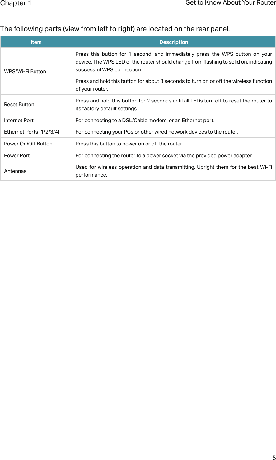
TP Link Technologies C50V5 AC1200 Wireless Dual Band Router/ AC1200 Dual Band Wi-Fi Router User Manual 5 Users Manual

TP-Link Technologies Co., Ltd. AC1200 Wireless Dual Band Router/ AC1200 Dual Band Wi-Fi Router 5 Users Manual

5. Users Manual

REV5.0.0     1910012355User GuideAC1200 Wireless Dual Band Router
ContentsAbout This Guide .........................................................................................................1Chapter 1.  Get to Know About Your Router  . . . . . . . . . . . . . . . . . . . . . . . . . . .21. 1.  Product Overview. . . . . . . . . . . . . . . . . . . . . . . . . . . . . . . . . . . . . . . . . . . . . . . . . . . . . . . . . . . . 31. 2.  Panel Layout. . . . . . . . . . . . . . . . . . . . . . . . . . . . . . . . . . . . . . . . . . . . . . . . . . . . . . . . . . . . . . . . . 31. 2. 1. Top View  . . . . . . . . . . . . . . . . . . . . . . . . . . . . . . . . . . . . . . . . . . . . . . . . . . . . . . . . . . . . . . 31. 2. 2. The Back Panel. . . . . . . . . . . . . . . . . . . . . . . . . . . . . . . . . . . . . . . . . . . . . . . . . . . . . . . . 4Chapter 2.  Connect to the Internet  . . . . . . . . . . . . . . . . . . . . . . . . . . . . . . . . . . .62. 1.  Position Your Router  . . . . . . . . . . . . . . . . . . . . . . . . . . . . . . . . . . . . . . . . . . . . . . . . . . . . . . . . .  72. 2.  Connect Your Router. . . . . . . . . . . . . . . . . . . . . . . . . . . . . . . . . . . . . . . . . . . . . . . . . . . . . . . . .  7Chapter 3.  Log In. . . . . . . . . . . . . . . . . . . . . . . . . . . . . . . . . . . . . . . . . . . . . . . . . . .  10Chapter 4.  Configure the Router in Wireless Router Mode . . . . . . . . . .  124. 1.  Status  . . . . . . . . . . . . . . . . . . . . . . . . . . . . . . . . . . . . . . . . . . . . . . . . . . . . . . . . . . . . . . . . . . . . . . 134. 2.  Quick Setup  . . . . . . . . . . . . . . . . . . . . . . . . . . . . . . . . . . . . . . . . . . . . . . . . . . . . . . . . . . . . . . . . 144. 3.  Operation Mode  . . . . . . . . . . . . . . . . . . . . . . . . . . . . . . . . . . . . . . . . . . . . . . . . . . . . . . . . . . . . 154. 3. 1. Wireless Router Mode . . . . . . . . . . . . . . . . . . . . . . . . . . . . . . . . . . . . . . . . . . . . . . . . 154. 3. 2. Access Point Mode. . . . . . . . . . . . . . . . . . . . . . . . . . . . . . . . . . . . . . . . . . . . . . . . . . . 154. 4.  Network  . . . . . . . . . . . . . . . . . . . . . . . . . . . . . . . . . . . . . . . . . . . . . . . . . . . . . . . . . . . . . . . . . . . . 164. 4. 1.  WAN. . . . . . . . . . . . . . . . . . . . . . . . . . . . . . . . . . . . . . . . . . . . . . . . . . . . . . . . . . . . . . . . 164. 4. 2.  LAN. . . . . . . . . . . . . . . . . . . . . . . . . . . . . . . . . . . . . . . . . . . . . . . . . . . . . . . . . . . . . . . . 224. 4. 3.  IPTV. . . . . . . . . . . . . . . . . . . . . . . . . . . . . . . . . . . . . . . . . . . . . . . . . . . . . . . . . . . . . . . . 224. 4. 4. MAC Clone . . . . . . . . . . . . . . . . . . . . . . . . . . . . . . . . . . . . . . . . . . . . . . . . . . . . . . . . . . . 234. 5.  Dual Band Selection  . . . . . . . . . . . . . . . . . . . . . . . . . . . . . . . . . . . . . . . . . . . . . . . . . . . . . . . . 244. 6.  Wireless (2.4GHz or 5GHz)  . . . . . . . . . . . . . . . . . . . . . . . . . . . . . . . . . . . . . . . . . . . . . . . . . . 244. 6. 1. Wireless Settings  . . . . . . . . . . . . . . . . . . . . . . . . . . . . . . . . . . . . . . . . . . . . . . . . . . . . 244. 6. 2.  WPS. . . . . . . . . . . . . . . . . . . . . . . . . . . . . . . . . . . . . . . . . . . . . . . . . . . . . . . . . . . . . . . . 264. 6. 3. Wireless Security  . . . . . . . . . . . . . . . . . . . . . . . . . . . . . . . . . . . . . . . . . . . . . . . . . . . . 284. 6. 4. Wireless Schedule  . . . . . . . . . . . . . . . . . . . . . . . . . . . . . . . . . . . . . . . . . . . . . . . . . . .304. 6. 5. Wireless MAC Filtering  . . . . . . . . . . . . . . . . . . . . . . . . . . . . . . . . . . . . . . . . . . . . . . . 304. 6. 6. Wireless Advanced. . . . . . . . . . . . . . . . . . . . . . . . . . . . . . . . . . . . . . . . . . . . . . . . . . . 324. 6. 7. Wireless Statistics  . . . . . . . . . . . . . . . . . . . . . . . . . . . . . . . . . . . . . . . . . . . . . . . . . . . 334. 7.  Guest Network. . . . . . . . . . . . . . . . . . . . . . . . . . . . . . . . . . . . . . . . . . . . . . . . . . . . . . . . . . . . . . 33
4. 8.  DHCP. . . . . . . . . . . . . . . . . . . . . . . . . . . . . . . . . . . . . . . . . . . . . . . . . . . . . . . . . . . . . . . . . . . . . . . 354. 8. 1. DHCP Settings  . . . . . . . . . . . . . . . . . . . . . . . . . . . . . . . . . . . . . . . . . . . . . . . . . . . . . . . 354. 8. 2. DHCP Client List  . . . . . . . . . . . . . . . . . . . . . . . . . . . . . . . . . . . . . . . . . . . . . . . . . . . . . 364. 8. 3. Address Reservation  . . . . . . . . . . . . . . . . . . . . . . . . . . . . . . . . . . . . . . . . . . . . . . . . . 374. 9.  Forwarding  . . . . . . . . . . . . . . . . . . . . . . . . . . . . . . . . . . . . . . . . . . . . . . . . . . . . . . . . . . . . . . . . . 374. 9. 1. Virtual Server  . . . . . . . . . . . . . . . . . . . . . . . . . . . . . . . . . . . . . . . . . . . . . . . . . . . . . . . . 384. 9. 2. Port Triggering  . . . . . . . . . . . . . . . . . . . . . . . . . . . . . . . . . . . . . . . . . . . . . . . . . . . . . . . 394. 9. 3.  DMZ. . . . . . . . . . . . . . . . . . . . . . . . . . . . . . . . . . . . . . . . . . . . . . . . . . . . . . . . . . . . . . . . 404. 9. 4.  UPnP. . . . . . . . . . . . . . . . . . . . . . . . . . . . . . . . . . . . . . . . . . . . . . . . . . . . . . . . . . . . . . . . 414. 10.  Security  . . . . . . . . . . . . . . . . . . . . . . . . . . . . . . . . . . . . . . . . . . . . . . . . . . . . . . . . . . . . . . . . . . . . 424. 10. 1. Basic Security  . . . . . . . . . . . . . . . . . . . . . . . . . . . . . . . . . . . . . . . . . . . . . . . . . . . . . . 424. 10. 2. Advanced Security. . . . . . . . . . . . . . . . . . . . . . . . . . . . . . . . . . . . . . . . . . . . . . . . . . 434. 10. 3. Local Management  . . . . . . . . . . . . . . . . . . . . . . . . . . . . . . . . . . . . . . . . . . . . . . . . . 454. 10. 4. Remote Management  . . . . . . . . . . . . . . . . . . . . . . . . . . . . . . . . . . . . . . . . . . . . . . . 454. 11.  Parental Controls  . . . . . . . . . . . . . . . . . . . . . . . . . . . . . . . . . . . . . . . . . . . . . . . . . . . . . . . . . . . 464. 12.  Access Control  . . . . . . . . . . . . . . . . . . . . . . . . . . . . . . . . . . . . . . . . . . . . . . . . . . . . . . . . . . . . . 474. 13.  Advanced Routing  . . . . . . . . . . . . . . . . . . . . . . . . . . . . . . . . . . . . . . . . . . . . . . . . . . . . . . . . . . 504. 13. 1. Static Route List  . . . . . . . . . . . . . . . . . . . . . . . . . . . . . . . . . . . . . . . . . . . . . . . . . . . . 504. 13. 2. System Routing Table . . . . . . . . . . . . . . . . . . . . . . . . . . . . . . . . . . . . . . . . . . . . . . . 514. 14.  Bandwidth Control . . . . . . . . . . . . . . . . . . . . . . . . . . . . . . . . . . . . . . . . . . . . . . . . . . . . . . . . . . 524. 14. 1. Control Settings  . . . . . . . . . . . . . . . . . . . . . . . . . . . . . . . . . . . . . . . . . . . . . . . . . . . . 524. 14. 2. Rule List  . . . . . . . . . . . . . . . . . . . . . . . . . . . . . . . . . . . . . . . . . . . . . . . . . . . . . . . . . . . . 524. 15.  IP & MAC Binding  . . . . . . . . . . . . . . . . . . . . . . . . . . . . . . . . . . . . . . . . . . . . . . . . . . . . . . . . . . . 534. 15. 1. Binding Settings  . . . . . . . . . . . . . . . . . . . . . . . . . . . . . . . . . . . . . . . . . . . . . . . . . . . . 534. 15. 2. ARP List  . . . . . . . . . . . . . . . . . . . . . . . . . . . . . . . . . . . . . . . . . . . . . . . . . . . . . . . . . . . . 544. 16.  Dynamic DNS. . . . . . . . . . . . . . . . . . . . . . . . . . . . . . . . . . . . . . . . . . . . . . . . . . . . . . . . . . . . . . . 554. 17.  IPv6  . . . . . . . . . . . . . . . . . . . . . . . . . . . . . . . . . . . . . . . . . . . . . . . . . . . . . . . . . . . . . . . . . . . . . . . . 574. 17. 1. IPv6 Status  . . . . . . . . . . . . . . . . . . . . . . . . . . . . . . . . . . . . . . . . . . . . . . . . . . . . . . . . . 574. 17. 2. IPv6 WAN . . . . . . . . . . . . . . . . . . . . . . . . . . . . . . . . . . . . . . . . . . . . . . . . . . . . . . . . . . . 584. 17. 3. IPv6 LAN. . . . . . . . . . . . . . . . . . . . . . . . . . . . . . . . . . . . . . . . . . . . . . . . . . . . . . . . . . . . 624. 18.  System Tools  . . . . . . . . . . . . . . . . . . . . . . . . . . . . . . . . . . . . . . . . . . . . . . . . . . . . . . . . . . . . . . . 634. 18. 1. Time Settings . . . . . . . . . . . . . . . . . . . . . . . . . . . . . . . . . . . . . . . . . . . . . . . . . . . . . . . 634. 18. 2. LED Control. . . . . . . . . . . . . . . . . . . . . . . . . . . . . . . . . . . . . . . . . . . . . . . . . . . . . . . . . 644. 18. 3. Feedback . . . . . . . . . . . . . . . . . . . . . . . . . . . . . . . . . . . . . . . . . . . . . . . . . . . . . . . . . . . 644. 18. 4. Diagnostic . . . . . . . . . . . . . . . . . . . . . . . . . . . . . . . . . . . . . . . . . . . . . . . . . . . . . . . . . . 654. 18. 5. Firmware Upgrade  . . . . . . . . . . . . . . . . . . . . . . . . . . . . . . . . . . . . . . . . . . . . . . . . . . 664. 18. 6. Factory Defaults  . . . . . . . . . . . . . . . . . . . . . . . . . . . . . . . . . . . . . . . . . . . . . . . . . . . . 674. 18. 7. Backup & Restore . . . . . . . . . . . . . . . . . . . . . . . . . . . . . . . . . . . . . . . . . . . . . . . . . . . 674. 18. 8. Reboot  . . . . . . . . . . . . . . . . . . . . . . . . . . . . . . . . . . . . . . . . . . . . . . . . . . . . . . . . . . . . . 68
4. 18. 9. Password . . . . . . . . . . . . . . . . . . . . . . . . . . . . . . . . . . . . . . . . . . . . . . . . . . . . . . . . . . . 694. 18. 10. System Log  . . . . . . . . . . . . . . . . . . . . . . . . . . . . . . . . . . . . . . . . . . . . . . . . . . . . . . . 694. 18. 11. Statistics . . . . . . . . . . . . . . . . . . . . . . . . . . . . . . . . . . . . . . . . . . . . . . . . . . . . . . . . . . 704. 19.  Log Out. . . . . . . . . . . . . . . . . . . . . . . . . . . . . . . . . . . . . . . . . . . . . . . . . . . . . . . . . . . . . . . . . . . . . 71Chapter 5.  Configure the Router in Access Point Mode . . . . . . . . . . . . .  725. 1.  Status  . . . . . . . . . . . . . . . . . . . . . . . . . . . . . . . . . . . . . . . . . . . . . . . . . . . . . . . . . . . . . . . . . . . . . . 735. 2.  Quick Setup  . . . . . . . . . . . . . . . . . . . . . . . . . . . . . . . . . . . . . . . . . . . . . . . . . . . . . . . . . . . . . . . . 745. 3.  Operation Mode  . . . . . . . . . . . . . . . . . . . . . . . . . . . . . . . . . . . . . . . . . . . . . . . . . . . . . . . . . . . . 745. 3. 1. Wireless Router Mode . . . . . . . . . . . . . . . . . . . . . . . . . . . . . . . . . . . . . . . . . . . . . . . . 745. 3. 2. Access Point Mode. . . . . . . . . . . . . . . . . . . . . . . . . . . . . . . . . . . . . . . . . . . . . . . . . . . 755. 4.  Network  . . . . . . . . . . . . . . . . . . . . . . . . . . . . . . . . . . . . . . . . . . . . . . . . . . . . . . . . . . . . . . . . . . . . 755. 5.  Dual Band Selection  . . . . . . . . . . . . . . . . . . . . . . . . . . . . . . . . . . . . . . . . . . . . . . . . . . . . . . . . 765. 6.  Wireless (2.4GHz or 5GHz)  . . . . . . . . . . . . . . . . . . . . . . . . . . . . . . . . . . . . . . . . . . . . . . . . . . 775. 6. 1. Wireless Settings  . . . . . . . . . . . . . . . . . . . . . . . . . . . . . . . . . . . . . . . . . . . . . . . . . . . . 775. 6. 2.  WPS. . . . . . . . . . . . . . . . . . . . . . . . . . . . . . . . . . . . . . . . . . . . . . . . . . . . . . . . . . . . . . . . 775. 6. 3. Wireless Security  . . . . . . . . . . . . . . . . . . . . . . . . . . . . . . . . . . . . . . . . . . . . . . . . . . . . 795. 6. 4. Wireless Schedule  . . . . . . . . . . . . . . . . . . . . . . . . . . . . . . . . . . . . . . . . . . . . . . . . . . .815. 6. 5. Wireless MAC Filtering  . . . . . . . . . . . . . . . . . . . . . . . . . . . . . . . . . . . . . . . . . . . . . . . 825. 6. 6. Wireless Advanced. . . . . . . . . . . . . . . . . . . . . . . . . . . . . . . . . . . . . . . . . . . . . . . . . . . 835. 6. 7. Wireless Statistics  . . . . . . . . . . . . . . . . . . . . . . . . . . . . . . . . . . . . . . . . . . . . . . . . . . . 855. 6. 8. Throughput Monitor . . . . . . . . . . . . . . . . . . . . . . . . . . . . . . . . . . . . . . . . . . . . . . . . . . 855. 7.  Guest Network. . . . . . . . . . . . . . . . . . . . . . . . . . . . . . . . . . . . . . . . . . . . . . . . . . . . . . . . . . . . . . 865. 8.  DHCP. . . . . . . . . . . . . . . . . . . . . . . . . . . . . . . . . . . . . . . . . . . . . . . . . . . . . . . . . . . . . . . . . . . . . . . 875. 8. 1. DHCP Settings  . . . . . . . . . . . . . . . . . . . . . . . . . . . . . . . . . . . . . . . . . . . . . . . . . . . . . . . 885. 8. 2. DHCP Client List  . . . . . . . . . . . . . . . . . . . . . . . . . . . . . . . . . . . . . . . . . . . . . . . . . . . . . 895. 8. 3. Address Reservation  . . . . . . . . . . . . . . . . . . . . . . . . . . . . . . . . . . . . . . . . . . . . . . . . . 895. 9.  System Tools  . . . . . . . . . . . . . . . . . . . . . . . . . . . . . . . . . . . . . . . . . . . . . . . . . . . . . . . . . . . . . . . 905. 9. 1. Time Settings  . . . . . . . . . . . . . . . . . . . . . . . . . . . . . . . . . . . . . . . . . . . . . . . . . . . . . . . . 905. 9. 2. LED Control . . . . . . . . . . . . . . . . . . . . . . . . . . . . . . . . . . . . . . . . . . . . . . . . . . . . . . . . . . 915. 9. 3. Feedback  . . . . . . . . . . . . . . . . . . . . . . . . . . . . . . . . . . . . . . . . . . . . . . . . . . . . . . . . . . . . 925. 9. 4. Diagnostic  . . . . . . . . . . . . . . . . . . . . . . . . . . . . . . . . . . . . . . . . . . . . . . . . . . . . . . . . . . . 925. 9. 5. Firmware Upgrade. . . . . . . . . . . . . . . . . . . . . . . . . . . . . . . . . . . . . . . . . . . . . . . . . . . .945. 9. 6. Factory Defaults  . . . . . . . . . . . . . . . . . . . . . . . . . . . . . . . . . . . . . . . . . . . . . . . . . . . . . 945. 9. 7. Backup & Restore  . . . . . . . . . . . . . . . . . . . . . . . . . . . . . . . . . . . . . . . . . . . . . . . . . . . . 955. 9. 8. Reboot . . . . . . . . . . . . . . . . . . . . . . . . . . . . . . . . . . . . . . . . . . . . . . . . . . . . . . . . . . . . . . . 955. 9. 9. Password  . . . . . . . . . . . . . . . . . . . . . . . . . . . . . . . . . . . . . . . . . . . . . . . . . . . . . . . . . . . . 965. 9. 10. System Log. . . . . . . . . . . . . . . . . . . . . . . . . . . . . . . . . . . . . . . . . . . . . . . . . . . . . . . . . 97
5. 9. 11. Statistics  . . . . . . . . . . . . . . . . . . . . . . . . . . . . . . . . . . . . . . . . . . . . . . . . . . . . . . . . . . . 975. 10.  Log Out. . . . . . . . . . . . . . . . . . . . . . . . . . . . . . . . . . . . . . . . . . . . . . . . . . . . . . . . . . . . . . . . . . . . . 98FAQ ................................................................................................................................99
1About This GuideThis guide is a complement to Quick Installation Guide. The Quick Installation Guide provides instructions for quick internet setup, while this guide contains details of each function and demonstrates how to configure them. When using this guide, please notice that features of the router may vary slightly depending on the model and software version you have, and on your location, language, and internet service provider. All screenshots, images, parameters and descriptions documented in this guide are used for demonstration only.ConventionsIn this guide the following conventions are used:Convention DescriptionUnderlined Underlined words or phrases are hyperlinks. You can click to redirect to a website or a specific section.Teal Contents to be emphasized and texts on the web page are in teal, including the menus, items, buttons and so on.>The menu structures to show the path to load the corresponding page. For example, Advanced > Wireless > MAC Filtering means the MAC Filtering function page is under the Wireless menu that is located in the Advanced tab.Note: Ignoring this type of note might result in a malfunction or damage to the device.Tips: Indicates important information that helps you make better use of your device.More InfoThe latest software, management app and utility are available from the Download Center at www.tp-link.com/support.The Quick Installation Guide can be found where you find this guide or inside the package of the router.Specifications can be found on the product page at http://www.tp-link.com.A Technical Support Forum is provided for you to discuss our products at  http://forum.tp-link.com.Our Technical Support contact information can be found at the Contact Technical Support page at www.tp-link.com/support.
Chapter 1Get to Know About Your RouterThis chapter introduces what the router can do and shows its appearance. It contains the following sections:•  Product Overview•  Panel Layout
3Chapter 1  Get to Know About Your Router1. 1.  Product OverviewThe TP-Link router is designed to fully meet the need of Small Office/Home Office (SOHO) networks and users demanding higher networking performance. The powerful antennas ensure continuous Wi-Fi signal to all your devices while boosting widespread coverage throughout your home, and the built-in Ethernet ports supply high-speed connection to your wired devices.Moreover, it is simple and convenient to set up and use the TP-Link router due to its intuitive web interface and the powerful Tether app.1. 2.  Panel Layout1. 2. 1.  Top ViewThe router’s LEDs (view from left to right) are located on the front panel. You can check the router’s working status by following the LED Explanation table.
4Chapter 1  Get to Know About Your RouterLED ExplanationName Status Indication (Power)On The system has started up successfully.Flashing The system is starting up or firmware is being upgraded. Do not disconnect or power off your router.Off Power is off. (2.4GHz Wireless)On The 2.4GHz wireless band is enabled.Off The 2.4GHz wireless band is disabled. (5GHz Wireless)On The 5GHz wireless band is enabled.Off The 5GHz wireless band is disabled. (Internet)Green On Internet service is available.Orange On The router’s Internet port is connected, but the internet is not available.Off The router’s Internet port is not connected. (Ethernet)On At least one Ethernet port is connected to a powered-on device.Off No Ethernet port is connected to a powered-on device. (WPS)On A WPS connection is established.Flashing A WPS connection is in progress. This may take up to 2 minutes.Off A WPS connection has been established for more than 5 minutes or WPS connection failed.1. 2. 2.  The Back Panel
5Chapter 1  Get to Know About Your RouterThe following parts (view from left to right) are located on the rear panel. Item DescriptionWPS/Wi-Fi ButtonPress this button for 1 second, and immediately press the WPS button on your device. The WPS LED of the router should change from flashing to solid on, indicating successful WPS connection.Press and hold this button for about 3 seconds to turn on or off the wireless function of your router.Reset Button Press and hold this button for 2 seconds until all LEDs turn off to reset the router to its factory default settings.Internet Port For connecting to a DSL/Cable modem, or an Ethernet port.Ethernet Ports (1/2/3/4) For connecting your PCs or other wired network devices to the router.Power On/Off Button Press this button to power on or off the router.Power Port For connecting the router to a power socket via the provided power adapter.Antennas Used for wireless operation and data transmitting. Upright them for the best Wi-Fi performance.
Chapter 2Connect to the InternetThis chapter contains the following sections:•  Position Your Router•  Connect Your Router
7Chapter 2  Connect to the Internet2. 1.  Position Your Router•  The product should not be located in a place where it will be exposed to moisture or excessive heat.•  Place the router in a location where it can be connected to multiple devices as well as to a power source.•  Make sure the cables and power cord are safely placed out of the way so they do not create a tripping hazard.•  The router can be placed on a shelf or desktop.•  Keep the router away from strong devices with strong electromagnetic interference, such as Bluetooth devices, cordless phones and microwaves.2. 2.  Connect Your RouterThis mode enables multiple users to share internet connection via ADSL/Cable Modem.1. Follow the steps below to connect your router.If your internet connection is through an Ethernet cable directly from the wall instead of through a DSL / Cable / Satellite modem, connect the Ethernet cable to the router’s Internet port, and then follow Step 4 and 5 to complete the hardware connection.ModemRouterPower adapterConnect to the power socketConnect to the internetPowerInternet3RZHU2Q2Ƭ1 )  Turn off the modem, and remove the backup battery if it has one.2 )  Connect the modem to the router’s Internet port with an Ethernet cable.3 )  Turn on the modem, and then wait about 2 minutes for it to restart.4 )  Connect the power adapter to the router and turn on the router.
8Chapter 2  Connect to the Internet5 )  Verify that the hardware connection is correct by checking these LEDs.PowerOn5GOn OnInternet2.4GOnNote:If the 2.4G and 5G Wi-Fi LEDs are off, press and hold the Wi-Fi/WPS button on the rear panel for about 3 seconds, then release the button. Both LEDs will turn on.2. Connect your computer to the router.•  Method 1: WiredTurn off the Wi-Fi on your computer and connect the devices as shown below.Ethernet cable•  Method 2: Wirelessly1 )  Find the SSID (Network Name) and Wireless Password printed on the label at the bottom of the router.2 )  Click the network icon of your computer or go to Wi-Fi Settings of your smart device, and then select the SSID to join the network.ORConnections are availableWireless Network ConnectionConnect automatically ConnectTP-Link_XXXXTP-Link_XXXX_5GWi-FiWi-Fi TP-Link_XXXXTP-Link_XXXX_5GCHOOSE A NETWORK...Other...< SettingsSmart DeviceComputer•  Method 3: Use the WPS buttonWireless devices that support WPS, including Android phones, tablets and most USB network cards, can be connected to your router through this method ( not supported by iOS devices).Note:The WPS function cannot be configured if the wireless function of the router is disabled. Also, the WPS function will be disabled if your wireless encryption is WEP. Please make sure the wireless function is enabled and is configured with the appropriate encryption before configuring the WPS.1 )  Tab the WPS icon on the device’s screen. Here we take an Android phone as an example.
9Chapter 2  Connect to the Internet2 )  Immediately press the WPS button on your router.WLANOnTP-LINKYSLDavidHotdogTs_5GSunnyTestResetWPS/W-FiWPSWPSWPSW-FWFClose to
Chapter 3Log InThis chapter introduces how to log in to the web management page of router.
11Chapter 3 Log InWith the web management page, it is easy to configure and manage the router. The web management page can be used on any Windows, Macintosh or UNIX OS with a Web browser, such as Microsoft the Internet Explorer, Mozilla Firefox or Apple Safari.Follow the steps below to log in to your router.1. Set up the TCP/IP Protocol in Obtain an IP address automatically mode on your computer.2. Visit http://tplinkwifi.net, and log in with the username and password you set for the router. The default one is admin (all lowercase) for both username and password.Note:If the login window does not appear, please refer to the FAQ section.3. For security purposes, go to System Tools > Password and create a new username and password for future logins.
Chapter 4Configure the Router in Wireless Router Mode This chapter presents how to configure the various features of the router working as a wireless router.  It contains the following sections:•  Status•  Quick Setup•  Operation Mode•  Network•  Dual Band Selection•  Wireless (2.4GHz or 5GHz)•  Guest Network•  DHCP•  Forwarding•  Security•  Parental Controls•  Access Control•  Advanced Routing•  Bandwidth Control•  IP & MAC Binding•  Dynamic DNS•  IPv6•  System Tools•  Log Out
13Chapter 4 &RQƮJXUHWKH5RXWHULQ:LUHOHVV5RXWHU0RGH4. 1.  Status1. Visit http://tplinkwifi.net, and log in with the username and password you set for the router.2. Go to Status. You can view the current status information of the router.•  Firmware Version - The version information of the router’s firmware.•  Hardware Version - The version information of the router’s hardware.•  LAN - This field displays the current settings of the LAN, and you can configure them on the Network > LAN page. •  MAC address - The physical address of the router.•  IP address - The LAN IP address of the router.•  Subnet Mask - The subnet mask associated with the LAN IP address.•  Wireless 2.4GHz/5GHz - This field displays the basic information or status of the wireless function, and you can configure them on the Wireless > Basic Settings page. •  Operation Mode - The current wireless working mode in use.
14Chapter 4 &RQƮJXUHWKH5RXWHULQ:LUHOHVV5RXWHU0RGH•  Wireless Radio - Indicates whether the wireless radio feature of the Router is enabled or disabled.•  Name(SSID) - The SSID of the Router.•  Mode - The current wireless mode which the router works on.•  Channel - The current wireless channel in use.•  Channel Width - The current wireless channel width in use.•  MAC Address - The physical address of the router.•  WDS Status - The status of the WDS connection is displayed.•  WAN - This field displays the current settings of the WAN, and you can configure them on the Network > WAN page.•  MAC Address - The physical address of the Internet port.•  IP Address - The current WAN (Internet) IP Address. This field will be blank or 0.0.0.0 if the IP Address is assigned dynamically and there is no internet connection.•  Subnet Mask - The subnet mask associated with the WAN IP Address.•  Default Gateway - The Gateway currently used is shown here. When you use Dynamic IP as the internet connection type, click Renew  or  Release here to obtain new IP parameters dynamically from the ISP or release them.•  DNS Server - The IP addresses of DNS (Domain Name System) server.•  System Up Time - The length of the time since the router was last powered on or reset.Click Refresh to get the latest status and settings of the router.4. 2.  Quick Setup1. Visit http://tplinkwifi.net, and log in with the username and password you set for the router.2. Go to Quick Setup. 3. Click Next to start. Then follow the step-by-step instructions to connect your router to the internet.
15Chapter 4 &RQƮJXUHWKH5RXWHULQ:LUHOHVV5RXWHU0RGH4. 3.  Operation ModeThe router supports two operation modes: Wireless Router mode and Access Point mode. 4. 3. 1.  Wireless Router ModeThe default Wireless Router mode is required most commonly. In this mode, the device enables multiple users to share the internet connection via ADSL/Cable Modem.For hardware connection, refer to Connect Your Router.4. 3. 2.  Access Point ModeIn this mode, this device can be connected to a wired network and transform the wired access into wireless one. If you already have a wired router, you can use this mode. Refer to Configure the Router in Access Point Mode session for detailed information.DevicesRouterWired RouterEthernet4Ethernet3Ethernet1Ethernet2InternetEthernet2Internet1. Find the router’s Internet port, and connect it to the Ethernet port (LAN port) of your existing wired router. Then connect the power adapter and turn on the router. 2. Connect your computer to the router via an Ethernet cable or wirelessly by using the SSID (network name) and Wireless Password printed on the label at the bottom of the router. For details, refer to Connect Your Router.3. Visit http://tplinkwifi.net, and log in with the username and password you set for the router.4. Go to Operation Mode.5. Select the Access Point mode and click Save.
16Chapter 4 &RQƮJXUHWKH5RXWHULQ:LUHOHVV5RXWHU0RGH4. 4.  Network4. 4. 1.  WAN1. Visit http://tplinkwifi.net, and log in with the username and password you set for the router.2. Go to Network > WAN.3. Configure the IP parameters of the LAN and click Save.Dynamic IPIf your ISP provides the DHCP service, please select Dynamic IP, and the router will automatically get IP parameters from your ISP.Click Renew to renew the IP parameters from your ISP. Click Release to release the IP parameters.•  MTU Size - The normal MTU (Maximum Transmission Unit) value for most Ethernet networks is 1500 Bytes. It is not recommended that you change the default MTU size unless required by your ISP. •  Get IP with Unicast - A few ISPs’ DHCP servers do not support the broadcast applications. If you cannot get the IP address normally, you can choose this option. (It is rarely required.)•  Set DNS server manually - If your ISP gives you one or two DNS addresses, select Set DNS server manually and enter the primary and secondary addresses into the correct fields. Otherwise, the DNS servers will be assigned automatically from your ISP.•  Host Name - This option specifies the name of the router.Static IPIf your ISP provides a static or fixed IP address, subnet mask, default gateway and DNS setting, please select Static IP.
17Chapter 4 &RQƮJXUHWKH5RXWHULQ:LUHOHVV5RXWHU0RGH•  IP Address - Enter the IP address in dotted-decimal notation provided by your ISP.•  Subnet Mask - Enter the subnet mask in dotted-decimal notation provided by your ISP. Normally 255.255.255.0 is used as the subnet mask.•  Gateway - Enter the gateway IP address in dotted-decimal notation provided by your ISP.•  Primary/Secondary DNS Server - (Optional) Enter one or two DNS addresses in dotted-decimal notation provided by your ISP.•  MTU (Bytes) - The normal MTU (Maximum Transmission Unit) value for most Ethernet networks is 1500 Bytes. It is not recommended that you change the default MTU size unless required by your ISP. PPPoEIf your ISP provides PPPoE connection, select PPPoE.•  Username/Password - Enter the user name and password provided by your ISP. These fields are case-sensitive.•  Confirm Password - Enter the password provided by your ISP again to ensure the password you entered is correct. •  Secondary Connection - It’s available only for PPPoE connection. If your ISP provides an extra connection type, select Dynamic IP or Static IP to activate the secondary connection.
18Chapter 4 &RQƮJXUHWKH5RXWHULQ:LUHOHVV5RXWHU0RGH•  Connection Mode•  Always On - In this mode, the internet connection will be active all the time.•  Connect on Demand - In this mode, the internet connection can be terminated automatically after a specified inactivity period (Max Idle Time) and be re-established when you attempt to access the internet again. If you want to keep your internet connection active all the time, please enter 0 in the Max Idle Time field. Otherwise, enter the number of minutes you want to have elapsed before your internet access disconnects.•  Connect Manually - You can click Connect/Disconnect to connect/disconnect immediately. This mode also supports the Max Idle Time function as Connect on Demand mode. The internet connection can be disconnected automatically after a specified inactivity period (Max Idle Time) and not be able to re-establish when you attempt to access the internet again.•  Authentication Type - Choose an authentication type. Note:Sometimes the connection cannot be terminated although you have specified the Max Idle Time because some applications are visiting the internet continually in the background.If you want to do some advanced configurations, please click Advanced.•  Service Name/Server Name - The service name and server name should not be configured unless you are sure it is necessary for your ISP. In most cases, leaving these fields blank will work.•  MTU (Bytes) - The default MTU size is 1480 bytes. It is not recommended that you change the default MTU size unless required by your ISP.•  ISP Specified IP Address - If your ISP does not automatically assign IP addresses to the router, please select Use IP address specified by ISP and enter the IP address provided by your ISP in dotted-decimal notation.•  Detect Online Interval - The router will detect Access Concentrator online at every interval. The default value is 0. You can input the value between 0 and 120. The value 0 means no detect.
19Chapter 4 &RQƮJXUHWKH5RXWHULQ:LUHOHVV5RXWHU0RGH•  Primary DNS/Secondary DNS - If your ISP does not automatically assign DNS addresses to the router, please select Set DNS server manually and enter the IP address in dotted-decimal notation of your ISP’s primary DNS server. If a secondary DNS server address is available, enter it as well.L2TPIf your ISP provides L2TP connection, please select L2TP.•  Username/Password - Enter the user name and password provided by your ISP. These fields are case-sensitive.•  Addressing Type - Choose the addressing type given by your ISP, either Dynamic IP or Static IP. Click the Connect button to connect immediately. Click the Disconnect button to disconnect immediately.•  MTU(Bytes) - The default MTU size is “1460” bytes, which is usually fine. It is not recommended that you change the default MTU Size unless required by your ISP. •  Enable IGMP Proxy - IGMP (Internet Group Management Protocol) is used to manage multicasting on TCP/IP networks. Some ISPs use IGMP to perform remote configuration for client devices, such as the modem router. The default value is enabled, and if you are not sure, please contact your ISP or just leave it. •  Connection Mode•  Always On - In this mode, the internet connection will be active all the time.•  Connect on Demand - In this mode, the internet connection can be terminated automatically after a specified inactivity period (Max Idle Time) and be re-established when you attempt to access the internet again. If you want to keep
20Chapter 4 &RQƮJXUHWKH5RXWHULQ:LUHOHVV5RXWHU0RGHyour internet connection active all the time, please enter 0 in the Max Idle Time field. Otherwise, enter the number of minutes you want to have elapsed before your internet access disconnects.•  Connect Manually - You can click Connect/Disconnect to connect/disconnect immediately. This mode also supports the Max Idle Time function as Connect on Demand mode. The internet connection can be disconnected automatically after a specified inactivity period (Max Idle Time) and not be able to re-establish when you attempt to access the internet again.Note:Sometimes the connection cannot be terminated although you have specified the Max Idle Time because some applications are visiting the internet continually in the background.PPTPIf your ISP provides PPTP connection, please select PPTP.•  Username/Password - Enter the user name and password provided by your ISP. These fields are case-sensitive.•  Addressing Type - Choose the addressing type given by your ISP, either Dynamic IP or Static IP. Click the Connect button to connect immediately. Click the Disconnect button to disconnect immediately.•  MTU(Bytes) - The default MTU size is “1460” bytes, which is usually fine. It is not recommended that you change the default MTU Size unless required by your ISP.
21Chapter 4 &RQƮJXUHWKH5RXWHULQ:LUHOHVV5RXWHU0RGH•  Connection Mode•  Always On - In this mode, the internet connection will be active all the time.•  Connect on Demand - In this mode, the internet connection can be terminated automatically after a specified inactivity period (Max Idle Time) and be re-established when you attempt to access the internet again. If you want to keep your internet connection active all the time, please enter 0 in the Max Idle Time field. Otherwise, enter the number of minutes you want to have elapsed before your internet access disconnects.•  Connect Manually - You can click Connect/Disconnect to connect/disconnect immediately. This mode also supports the Max Idle Time function as Connect on Demand mode. The internet connection can be disconnected automatically after a specified inactivity period (Max Idle Time) and not be able to re-establish when you attempt to access the internet again.Note:Sometimes the connection cannot be terminated although you have specified the Max Idle Time because some applications are visiting the internet continually in the background.BigPond CableIf your ISP provides BigPond cable connection, please select BigPond Cable.•  Username/Password - Enter the user name and password provided by your ISP. These fields are case-sensitive.•  Auth Server - Enter the authenticating server IP address or host name.•  Auth Domain - Type in the domain suffix server name based on your location.•  MTU(Bytes) - The default MTU size is 1480 bytes. It is not recommended that you change the default MTU size unless required by your ISP.
22Chapter 4 &RQƮJXUHWKH5RXWHULQ:LUHOHVV5RXWHU0RGH•  Connection Mode•  Always On - In this mode, the internet connection will be active all the time.•  Connect on Demand - In this mode, the internet connection can be terminated automatically after a specified inactivity period (Max Idle Time) and be re-established when you attempt to access the internet again. If you want to keep your internet connection active all the time, please enter 0 in the Max Idle Time field. Otherwise, enter the number of minutes you want to have elapsed before your internet access disconnects.•  Connect Manually - You can click Connect/Disconnect to connect/disconnect immediately. This mode also supports the Max Idle Time function as Connect on Demand mode. The internet connection can be disconnected automatically after a specified inactivity period (Max Idle Time) and not be able to re-establish when you attempt to access the internet again.4. 4. 2.  LAN1. Visit http://tplinkwifi.net, and log in with the username and password you set for the router.2. Go to Network > LAN. 3. Configure the IP parameters of the LAN and click Save.•  MAC Address - The physical address of the LAN ports. The value can not be changed.•  IP Address - Enter the IP address in dotted-decimal notation of your router.•  Subnet Mask - An address code that determines the size of the network. Normally 255.255.255.0 is used as the subnet mask.Note:•  If you have changed the IP address, you must use the new IP address to log in.•  If the new IP address you set is not in the same subnet as the old one, the IP address pool in the DHCP Server will be configured automatically, but the Virtual Server and DMZ Host will not take effect until they are re-configured.4. 4. 3.  IPTV1. Visit http://tplinkwifi.net, and log in with the username and password you set for the router.
23Chapter 4 &RQƮJXUHWKH5RXWHULQ:LUHOHVV5RXWHU0RGH2. Go to Network > IPTV.3. Configure IPTV settings and click Save.•  IGMP Snooping - IGMP snooping is designed to prevent hosts on a local network from receiving traffic for a multicast group they have not explicitly joined. IGMP snooping is especially useful for bandwidth-intensive IP multicast applications such as IPTV.•  IGMP Proxy - Select to enable IGMP Proxy.•  IGMP Version - Select the IGMP(Internet Group Management Protocol) Proxy Version, either V2 or V3, according to your ISP.•  IPTV - Select to enable the IPTV feature.•  Mode - Select the appropriate mode according to your ISP.•  LAN 1/2/3/4 - Assign your LAN port to whether function as the Internet supplier or as the IPTV supplier.4. 4. 4.  MAC Clone1. Visit http://tplinkwifi.net, and log in with the username and password you set for the router.2. Go to Network > MAC Clone.3. Configure the WAN MAC address and click Save.•  WAN MAC Address - This field displays the current MAC address of the Internet port. If your ISP requires you to register the MAC address, please enter the correct
24Chapter 4 &RQƮJXUHWKH5RXWHULQ:LUHOHVV5RXWHU0RGHMAC address in this field. Click Restore Factory MAC to restore the MAC address of Internet port to the factory default value.•  Your PC’s MAC Address - This field displays the MAC address of the PC that is managing the router. If the MAC address is required, you can click Clone MAC Address and this MAC address will be filled in the WAN MAC Address field.Note:•  You can only use the MAC Address Clone function for PCs on the LAN.•  If you have changed the WAN MAC address when the WAN connection is PPPoE, it will not take effect until the connection is re-established.4. 5.  Dual Band Selection1. Visit http://tplinkwifi.net, and log in with the username and password you set for the router.2. Go to Dual Band Selection. 3. Select the working radio band as needed and click Save.4. 6.  Wireless (2.4GHz or 5GHz)4. 6. 1.  Wireless Settings1. Visit http://tplinkwifi.net, and log in with the username and password you set for the router.2. Go to Wireless > Basic Settings. 3. Configure the basic settings for the wireless network and click Save.
25Chapter 4 &RQƮJXUHWKH5RXWHULQ:LUHOHVV5RXWHU0RGH•  Wireless - Enable or disable wireless network.•  Wireless Network Name -  Enter a value of up to 32 characters. The same Name (SSID) must be assigned to all wireless devices in your network.•  Mode - You can choose the appropriate “Mixed” mode.•  Channel - This field determines which operating frequency will be used. The default channel is set to Auto. It is not necessary to change the wireless channel unless you notice interference problems with another nearby access point.•  Channel Width - This field determines which operating frequency will be used. It is not necessary to change the wireless channel unless you notice interference problems with another nearby access point. If you select auto, then AP will choose the best channel automatically.•  Enable SSID Broadcast - If enabled, the router will broadcast the wireless network name (SSID).•  Enable WDS - You can select this to enable WDS Bridging, with this function, the router can bridge two or more WLANs. NOTE: If this checkbox is selected, you had better make sure the following settings are correct. •  SSID (to be bridged) - The SSID of the AP your Router is going to connect to as a client. You can also use the scan function to select the SSID to join.•  MAC Address (to be bridged) - The MAC Address of the AP your Router is going to connect to as a client. You can also use the scan function to select the MAC Address to join.•  Scan - Click this button, you can search the AP which runs in the current channel.
26Chapter 4 &RQƮJXUHWKH5RXWHULQ:LUHOHVV5RXWHU0RGH•  Key Type - This option should be chosen according to the AP’s security configuration.It is recommended that the security type is the same as your AP’s security type•  WEP Index - This option should be chosen if the key type is WEP(ASCII) or WEP(HEX).It indicates the index of the WEP key.•  Authentication Type - This option should be chosen if the key type is WEP(ASCII) or WEP(HEX). It indicates the authorization type of the Root AP.•  Encryption - Please select encryption type base on the source AP.•  Password - If the AP your Router is going to connect needs password, you need to fill the password in this blank.4. 6. 2.  WPSWPS (Wi-Fi Protected Setup) can help you to quickly and securely connect to a network. This section will guide you to add a wireless device to your router’s network via WPS.Note:The WPS function cannot be configured if the wireless function of the router is disabled. Please make sure the wireless function is enabled before configuration.1. Visit http://tplinkwifi.net, and log in with the username and password you set for the router.2. Go to Wireless > WPS. 3. Follow a method below to connect your client device to the router’s Wi-Fi network.Method 1: Press the WPS Buttons on the Router and Client DeviceFor details, refer to Method 3: Use the WPS button of Connect Your Router.Method 2: Press the WPS Button on Your Client Device1. Keep the WPS Status as Enabled and click Add Device.2. Select Press the WPS button of the new device within the next two minutes and click Connect.
27Chapter 4 &RQƮJXUHWKH5RXWHULQ:LUHOHVV5RXWHU0RGH3. Within two minutes, press the WPS button on your client device.4. A success message will appear on the WPS page if the client device has been successfully added to the router’s network.Method 3: Enter the Client’s PIN1. Keep the WPS Status as Enabled and click Add Device.2. Select Enter new device PIN, enter your client device’s current PIN in the PIN filed and click Connect.3. A success message will appear on the WPS page if the client device has been successfully added to the router’s network.Method 4: Enter the Router’s PIN1. Keep the WPS Status as Enabled and get the Current PIN of the router.
28Chapter 4 &RQƮJXUHWKH5RXWHULQ:LUHOHVV5RXWHU0RGH2. Enter the router’s current PIN on your client device to join the router’s Wi-Fi network.4. 6. 3.  Wireless Security1. Visit http://tplinkwifi.net, and log in with the username and password you set for the router.2. Go to Wireless > Wireless Security. 3. Configure the security settings of your wireless network and click Save.•  Disable Wireless Security - The wireless security function can be enabled or disabled. If disabled, wireless clients can connect to the router without a password. It’s strongly recommended to choose one of the following modes to enable security.
29Chapter 4 &RQƮJXUHWKH5RXWHULQ:LUHOHVV5RXWHU0RGH•  WPA-PSK/WPA2-Personal  -  It’s  the  WPA/WPA2  authentication  type  based  on                pre-shared passphrase. •  Authentication Type - Select Auto, WPA-PSK or WPA2-PSK.•  Encryption - Select Auto, TKIP or AES.•  Wireless Password - Enter ASCII or Hexadecimal characters. For Hexadecimal, the length should be between 8 and 64 characters; for ASCII, the length should be between 8 and 63 characters.•  Group Key Update Period - Specify the group key update interval in seconds. The value can be 0 or at least 30. Enter 0 to disable the update.•  WPA /WPA2-Enterprise - It’s based on Radius Server.•  Authentication Type - Select Auto, WPA or WPA2.•  Encryption - Select Auto, TKIP or AES.•  Radius Server IP - Enter the IP address of the Radius server.•  Radius Server Port - Enter the port that Radius server used.•  Radius Server Password - Enter the password for the Radius server.•  Group Key Update Period - Specify the group key update interval in seconds. The value should be 30 or above. Enter 0 to disable the update.•  WEP - It is based on the IEEE 802.11 standard. •  Authentication Type - The default setting is Auto, which can select Shared Key or Open System authentication type automatically based on the wireless client’s capability and request.•  WEP Key Format - Hexadecimal and ASCII formats are provided here. Hexadecimal format stands for any combination of hexadecimal digits (0-9, a-f, A-F) in the specified length. ASCII format stands for any combination of keyboard characters in the specified length. •  Selected Key - Select which of the four keys will be used and enter the matching WEP key. Make sure these values are identical on all wireless clients in your network. •  Key Type - Select the WEP key length (64-bit, 128-bit or 152-bit) for encryption. Disabled means this WEP key entry is invalid.•  64-bit - Enter 10 hexadecimal digits (any combination of 0-9, a-f and A-F. Null key is not permitted) or 5 ASCII characters. •  128-bit - Enter 26 hexadecimal digits (any combination of 0-9, a-f and A-F. Null key is not permitted) or 13 ASCII characters.
30Chapter 4 &RQƮJXUHWKH5RXWHULQ:LUHOHVV5RXWHU0RGH4. 6. 4.  Wireless ScheduleYou can automatically turn off your wireless network when you do not need the wireless connection. The time you set is the period you need the wireless off.Note:Before configure the Wireless Schedule, please go to System Tools > Time Settings page to set system time first, and then you can enable or disable Wireless Schedule.1. Visit http://tplinkwifi.net, and log in with the username and password you set for the router.2. Go to Wireless > Wireless Schedule. 3.  Configure the settings for the wireless network and click Save.•  Apply To - Select the day or days you need the wireless off.•  Start Time, End Time - You can select all day-24 hours or you may enter the Start Time and End Time in the corresponding field.•  Add - Click to add your selected time to the below table.•  Clear Schedule - Click to clear your settings in the table.4. 6. 5.  Wireless MAC FilteringWireless MAC Filtering is used to deny or allow specific wireless client devices to access your network by their MAC addresses.
31Chapter 4 &RQƮJXUHWKH5RXWHULQ:LUHOHVV5RXWHU0RGHDeny or allow specific wireless client devices to access my network by their MAC addresses.For example, you want the wireless client A with the MAC address 00:0A:EB:B0:00:0B and the wireless client B with the MAC address 00:0A:EB:00:07:5F to access the router, but other wireless clients cannot access the router1.  Visit  http://tplinkwifi.net, and log in with the username and password you set for the router.2.  Go to Wireless > Wireless MAC Filtering.3.  Click Enable to enable the Wireless MAC Filtering function.4.  Select Allow the stations specified by any enabled entries in the list to access as the filtering rule.5.  Delete all or disable all entries if there are any entries already.6.  Click Add New and fill in the blank.1 )  Enter the MAC address 00:0A:EB:B0:00:0B/00:0A:EB:00:07:5F in the MAC Address field.2 )  Enter wireless client A/B in the Description field.3 )  Select Enabled in the Status drop-down list.4 )  Click Save and click Back.7.  The configured filtering rules should be listed as the picture shows below.I want to:How can I do that?
32Chapter 4 &RQƮJXUHWKH5RXWHULQ:LUHOHVV5RXWHU0RGHNow only client A and client B can access your network.4. 6. 6.  Wireless Advanced1. Visit http://tplinkwifi.net, and log in with the username and password you set for the router.2. Go to Wireless > Wireless Advanced. 3. Configure the advanced settings of your wireless network and click Save. Note:If you are not familiar with the setting items on this page, it’s strongly recommended to keep the provided default values; otherwise it may result in lower wireless network performance.•  Transmit Power - Select High, Middle or Low which you would like to specify for the router. High is the default setting and recommended.•  Beacon Interval - Enter a value between 40-1000 milliseconds for Beacon Interval here. Beacon Interval value determines the time interval of the beacons. The beacons are the packets sent by the router to synchronize a wireless network. The default value is 100. •  RTS Threshold - Here you can specify the RTS (Request to Send) Threshold. If the packet is larger than the specified RTS Threshold size, the router will send RTS frames to a particular receiving station and negotiate the sending of a data frame. The default value is 2346. •  Fragmentation Threshold - This value is the maximum size determining whether packets will be fragmented. Setting a low value for the Fragmentation Threshold may result in poor network performance because of excessive packets. 2346 is the default setting and is recommended. Done!
33Chapter 4 &RQƮJXUHWKH5RXWHULQ:LUHOHVV5RXWHU0RGH•  DTIM Interval - This value determines the interval of the Delivery Traffic Indication Message (DTIM). A DTIM field is a countdown field informing clients of the next window for listening to broadcast and multicast messages. When the router has buffered broadcast or multicast messages for associated clients, it sends the next DTIM with a DTIM Interval value. You can specify the value between 1-255 Beacon Intervals. The default value is 1, which indicates the DTIM Interval is the same as Beacon Interval. •  Enable Short GI - It is recommended to enable this function, for it will increase the data capacity by reducing the guard interval time. •  Enable Client Isolation - This function isolates all connected wireless stations so that wireless stations cannot access each other through WLAN. This function will be disabled if WDS/Bridge is enabled.•  Enable WMM - WMM function can guarantee the packets with high-priority messages being transmitted preferentially. It is strongly recommended to enable this function.4. 6. 7.  Wireless Statistics1. Visit http://tplinkwifi.net, and log in with the username and password you set for the router.2. Go to Wireless > Wireless Statistics to check the data packets sent and received by each client device connected to the router.•  MAC Address - The MAC address of the connected wireless client.•  Current Status - The running status of the connected wireless client.•  Received Packets - Packets received by the wireless client.•  Sent Packets - Packets sent by the wireless client.•  SSID - SSID that the station associates with.4. 7.  Guest NetworkGuest Network allows you to provide Wi-Fi access for guests without disclosing your host network. When you have guests in your house, apartment, or workplace, you can create a guest network for them. In addition, you can customize guest network permissions to ensure network security and privacy.If you run a small shop, you can set up Facebook Wi-Fi.  It allows customers to easily connect to your Wi-Fi by redirecting them to your company’s Facebook page. Here, they
34Chapter 4 &RQƮJXUHWKH5RXWHULQ:LUHOHVV5RXWHU0RGHare encouraged to check in and like your page before receiving free web access. This raises the profile of your business on Facebook and increases customer engagement with promotional content on your page.1.  Visit http://tplinkwifi.net, and log in with the username and password you set for the router.2.  Go to Guest Network.3.  Customize guest network permissions.•  Allow Guest To Access My Local Network - If enabled, guests can access the local network and manage it. •  Guest Network Isolation - If enabled, guests are isolated from each other.•  Enable Guest Network Bandwidth Control - If enabled, the Guest Network Bandwidth Control rules will take effect.Note:The range of bandwidth for guest network is calculated according to the setting of Bandwidth Control on the Bandwidth Control page.4.  Select a band and enable the Guest Network function.5.  Create a network name for your guest network.6.  Configure the Security type.•  To configure a secure network, select WPA/WPA2 - Personal and create a password for the guest network.
35Chapter 4 &RQƮJXUHWKH5RXWHULQ:LUHOHVV5RXWHU0RGH•  To set up Facebook Wi-Fi, disable wireless security, enable Facebook Wi-Fi, click Set Up on Facebook, then follow the instructions to complete Facebook Wi-Fi settings.7.  Click Save.4. 8.  DHCPBy default, the DHCP (Dynamic Host Configuration Protocol) Server is enabled and the router acts as a DHCP server; it dynamically assigns TCP/IP parameters to client devices from the IP Address Pool. You can change the settings of DHCP Server if necessary, and you can reserve LAN IP addresses for specified client devices.4. 8. 1.  DHCP Settings1. Visit http://tplinkwifi.net, and log in with the username and password you set for the router.2. Go to DHCP > DHCP Settings. 3. Specify DHCP server settings and click Save.•  DHCP Server - Enable or disable the DHCP server. If disabled, you must have another DHCP server within your network or else you must configure the computer manually.•  Start IP Address - Specify an IP address for the DHCP Server to start with when assigning IP addresses.
36Chapter 4 &RQƮJXUHWKH5RXWHULQ:LUHOHVV5RXWHU0RGH•  End IP Address - Specify an IP address for the DHCP Server to end with when assigning IP addresses. •  Address Lease Time - The Address Lease Time is the amount of time a network user will be allowed to connect to the router with the current dynamic IP Address. When time is up, the user will be automatically assigned a new dynamic IP address. •  Default Gateway (Optional) - It is suggested to input the IP address of the LAN port of the router. •  Default Domain (Optional) - Input the domain name of your network.•  DNS Server (Optional) - Input the DNS IP address provided by your ISP.•  Secondary DNS Server (Optional) - Input the IP address of another DNS server if your ISP provides two DNS servers. Note:•  To use the DHCP server function of the router, you must configure all computers on the LAN as Obtain an IP Address automatically.• When you choose Smart IP (DHCP) in Network > LAN, the DHCP Server function will be disabled. You will see the page as below.4. 8. 2.  DHCP Client List1. Visit http://tplinkwifi.net, and log in with the username and password you set for the router.2. Go to DHCP > DHCP Client List to view the information of the clients connected to the router.•  Client Name - The name of the DHCP client.
37Chapter 4 &RQƮJXUHWKH5RXWHULQ:LUHOHVV5RXWHU0RGH•  MAC Address - The MAC address of the DHCP client. •  Assigned IP - The IP address that the outer has allocated to the DHCP client.•  Lease Time - The time of the DHCP client leased. After the dynamic IP address has expired, a new dynamic IP address will be automatically assigned to the user.  You cannot change any of the values on this page. To update this page and show the current attached devices, click Refresh.4. 8. 3.  Address ReservationYou can reserve an IP address for a specific client. When you specify a reserved IP address for a PC on the LAN, this PC will always receive the same IP address each time when it accesses the DHCP server.1. Visit http://tplinkwifi.net, and log in with the username and password you set for the router.2. Go to DHCP > Address Reservation.3. Click Add New and fill in the blank.1 )  Enter the MAC address (in XX-XX-XX-XX-XX-XX format.) of the client for which you want to reserve an IP address.2 )  Enter the IP address (in dotted-decimal notation) which you want to reserve for the client.3 )  Leave the Status as Enabled.4 )  Click Save.4. 9.  ForwardingThe router’s NAT (Network Address Translation) feature makes the devices on the LAN use the same public IP address to communicate in the internet, which protects the local network by hiding IP addresses of the devices. However, it also brings about the problem that external hosts cannot initiatively communicate with the specified devices in the local network.
38Chapter 4 &RQƮJXUHWKH5RXWHULQ:LUHOHVV5RXWHU0RGHWith the forwarding feature, the router can traverse the isolation of NAT so that clients on the internet can reach devices on the LAN and realize some specific functions.The TP-Link router includes four forwarding rules. If two or more rules are set, the priority of implementation from high to low is Virtual Servers, Port Triggering, UPNP and DMZ.4. 9. 1.  Virtual ServerWhen you build up a server in the local network and want to share it on the internet, Virtual Servers can realize the service and provide it to internet users. At the same time virtual servers can keep the local network safe as other services are still invisible from the internet.Virtual Servers can be used to set up public services in your local network, such as HTTP, FTP, DNS, POP3/SMTP and Telnet. Different service uses different service port. Port 80 is used in HTTP service, port 21 in FTP service, port 25 in SMTP service and port 110 in POP3 service. Please verify the service port number before the configuration.Share my personal website I’ve built in local network with my friends through the internet.For example, the personal website has been built in my home PC (192.168.0.100). I hope that my friends on the internet can visit my website in some way. My PC is connected to the router with the WAN IP address 218.18.232.154.Router WAN: 218.18.232.154LANHomePersonal Website 1.  Set your PC to a static IP address, for example 192.168.0.100.2.  Visit  http://tplinkwifi.net, and log in with the username and password you set for the router.3.  Go to Forwarding > Virtual Server.4.  Click  Add New. Select HTTP from the Common Service Port  list. The service port, internal port and protocol will be automatically filled in. Enter the PC’s IP address 192.168.0.100 in the IP Address field.I want to:
39Chapter 4 &RQƮJXUHWKH5RXWHULQ:LUHOHVV5RXWHU0RGH5.  Leave the status as Enabled and click Save.Note:•  It is recommended to keep the default settings of Internal Port and Protocol if you are not clear about which port and protocol to use.•  If the service you want to use is not in the Common Service Port list, you can enter the corresponding parameters manually. You should verify the port number that the service needs.•  You can add multiple virtual server rules if you want to provide several services in a router. Please note that the Service Port should not be overlapped.Users on the internet can enter http:// WAN IP (in this example: http:// 218.18.232.154) to visit your personal website.Note:•  If you have changed the default Service Port, you should use http:// WAN IP: Service Port to visit the website.•  Some specific service ports are forbidden by the ISP, if you fail to visit the website, please use another service port.4. 9. 2.  Port TriggeringPort triggering can specify a triggering port and its corresponding external ports. When a host in the local network initiates a connection to the triggering port, all the external ports will be opened for subsequent connections. The router can record the IP address of the host. When the data from the internet return to the external ports, the router can forward them to the corresponding host. Port triggering is mainly applied to online games, VoIPs, video players and common applications including MSN Gaming Zone, Dialpad, Quick Time 4 players and more.Follow the steps below to configure the port triggering rules:1. Visit http://tplinkwifi.net, and log in with the username and password you set for the router.2. Go to Forwarding > Port Triggering.3. Click Add New. Select the desired application from the Common Applications list. The trigger port amd incoming ports will be automatically filled in. The following picture takes application MSN Gaming Zone as an example.Done!
40Chapter 4 &RQƮJXUHWKH5RXWHULQ:LUHOHVV5RXWHU0RGH4. Leave the status as Enabled and click Save.Note:•  You can add multiple port triggering rules as needed.•  The triggering ports can not be overlapped.•  If the application you need is not listed in the Common Applications list, please enter the parameters manually. You should verify the incoming ports the application uses first and enter them in Incoming Ports field. You can input at most 5 groups of ports (or port sections). Every group of ports must be set apart with “,”. For example, 2000-2038, 2050-2051, 2085, 3010-3030.4. 9. 3.  DMZWhen a PC is set to be a DMZ (Demilitarized Zone) host in the local network, it is totally exposed to the Internet, which can realize the unlimited bidirectional communication between internal hosts and external hosts. The DMZ host becomes a virtual server with all ports opened. When you are not clear about which ports to open in some special applications, such as IP camera and database software, you can set the PC to be a DMZ host.Note:DMZ is more applicable in the situation that users are not clear about which ports to open. When it is enabled, the DMZ host is totally exposed to the internet, which may bring some potential safety hazards. If DMZ is not in use, please disable it in time.Make the home PC join the internet online game without port restriction.For example, due to some port restriction, when playing the online games, you can log in normally but cannot join a team with other players. To solve this problem, set your PC as a DMZ host with all ports opened.1.  Assign a static IP address to your PC, for example 192.168.0.100.2.  Visit  http://tplinkwifi.net, and log in with the username and password you set for the router.3.  Go to Forwarding > DMZ.I want to:How can I do that?
41Chapter 4 &RQƮJXUHWKH5RXWHULQ:LUHOHVV5RXWHU0RGH4.  Select Enable and enter the IP address 192.168.0.100 in the DMZ Host IP Address filed.5.  Click Save.You’ve set your PC to a DMZ host and now you can make a team to game with other players.4. 9. 4.  UPnPThe UPnP (Universal Plug and Play) protocol allows the applications or host devices to automatically find the front-end NAT device and send request to it to open the corresponding ports. With UPnP enabled, the applications or host devices on the local network and  the internet can freely communicate with each other realizing the seamless connection of the network. You may need to enable the UPnP if you want to use applications for multiplayer gaming, peer-to-peer connections, real-time communication (such as VoIP or telephone conference) or remote assistance, etc.Tips:•  UPnP is enabled by default in this router.•  Only the application supporting UPnP protocol can use this feature.•  UPnP feature needs the support of operating system (e.g. Windows Vista/ Windows 7/ Windows 8, etc. Some of operating system need to install the UPnP components).For example, when you connect your Xbox to the router which is connected to the internet to play online games, UPnP will send request to the router to open the corresponding ports allowing the following data penetrating the NAT to transmit. Therefore, you can play Xbox online games without a hitch.RouterXboxLAN WANIf necessary, you can follow the steps to change the status of UPnP.1. Visit http://tplinkwifi.net, and log in with the username and password you set for the router.2. Go to Forwarding > UPnP.3. Click Disable or Enable according to your needs.Done!
42Chapter 4 &RQƮJXUHWKH5RXWHULQ:LUHOHVV5RXWHU0RGH4. 10.  SecurityThis function allows you to protect your home network from cyber attacks and unauthorized users by implementing these network security functions.4. 10. 1.  Basic Security1. Visit http://tplinkwifi.net, and log in with the username and password you set for the router.2. Go to Security > Basic Security, and you can enable or disable the security functions.•  Firewall - A firewall protects your network from internet attacks.•  Enable SPI Firewall - SPI (Stateful Packet Inspection, also known as dynamic packet filtering) helps to prevent cyber attacks by tracking more state per
43Chapter 4 &RQƮJXUHWKH5RXWHULQ:LUHOHVV5RXWHU0RGHsession. It validates that the traffic passing through the session conforms to the protocol. SPI Firewall is enabled by default.•  VPN - VPN Passthrough must be enabled if you want to allow VPN tunnels using IPSec, PPTP or L2TP protocols to pass through the router’s firewall.•  PPTP Pass-through - Point-to-Point Tunneling Protocol (PPTP) allows the Point-to-Point Protocol (PPP) to be tunneled through an IP network. If you want to allow PPTP tunnels to pass through the router, you can keep the default (Enabled). •  L2TP Pass-through - Layer 2 Tunneling Protocol (L2TP) is the method used to enable Point-to-Point sessions via the internet on the Layer 2 level. If you want to allow L2TP tunnels to pass through the router, you can keep the default (Enabled).•  IPSec Pass-through - Internet Protocol Security (IPSec) is a suite of protocols for ensuring private, secure communications over Internet Protocol (IP) networks, through the use of cryptographic security services. If you want to allow IPSec tunnels to pass through the router,  you can keep the default (Enabled).•  ALG - It is recommended to enable Application Layer Gateway (ALG) because ALG allows customized Network Address Translation (NAT) traversal filters to be plugged into the gateway to support address and port translation for certain application layer “control/data” protocols such as FTP, TFTP, H323 etc. •  FTP ALG - To allow FTP clients and servers to transfer data across NAT, keep the default Enable. •  TFTP ALG - To allow TFTP clients and servers to transfer data across NAT, keep the default Enable.•  H323 ALG - To allow Microsoft NetMeeting clients to communicate across NAT, keep the default Enable.•  SIP ALG - To allow some multimedia clients to communicate across NAT, click Enable.•  RTSP ALG - To allow some media player clients to communicate with some streaming media servers across NAT, click Enable.3. Click Save.4. 10. 2.  Advanced Security1. Visit http://tplinkwifi.net, and log in with the username and password you set for the router.2. Go  to  Security  > Advanced Security, and you can protect the router from being attacked by ICMP-Flood, UDP Flood and TCP-SYN Flood.
44Chapter 4 &RQƮJXUHWKH5RXWHULQ:LUHOHVV5RXWHU0RGH •  DoS Protection - Denial of Service protection. Select Enable or Disable to enable or disable the DoS protection function. Only when it is enabled, will the flood filters be enabled.Note:Dos Protection will take effect only when the Statistics in System Tool > Statistics is enabled.•  Enable ICMP-Flood Attack Filtering -Check the box to enable or disable this function.•  ICMP-FLOOD Packets Threshold (5~3600) - The default value is 50. Enter a value between 5 ~ 3600. When the number of the current ICMP-FLOOD packets is beyond the set value, the router will startup the blocking function immediately.•  Enable UDP-FLOOD Filtering - Check the box to enable or disable this function.•  UDP-FLOOD Packets Threshold (5~3600) - The default value is 500. Enter a value between 5 ~ 3600. When the number of the current UPD-FLOOD packets is beyond the set value, the router will startup the blocking function immediately.•  Enable TCP-SYN-FLOOD Attack Filtering -Check the box to enable or disable this function.•  TCP-SYN-FLOOD Packets Threshold (5~3600) - The default value is 50. Enter a value between 5 ~ 3600. When the number of the current TCP-SYN-FLOOD packets is beyond the set value, the router will startup the blocking function immediately. •  Ignore Ping Packet From WAN Port - The default setting is disabled. If enabled, the ping packet from the internet cannot access the router. •  Forbid Ping Packet From LAN Port - The default setting is disabled. If enabled, the ping packet from LAN cannot access the router. This function can be used to defend against some viruses. 3. Click Save.4. Click Blocked DoS Host List to display the DoS host table by blocking.
45Chapter 4 &RQƮJXUHWKH5RXWHULQ:LUHOHVV5RXWHU0RGH4. 10. 3.  Local Management1. Visit http://tplinkwifi.net, and log in with the username and password you set for the router.2. Go  to  Security  >  Local Management, and you can block computers in LAN from accessing the router. For example, if you want to allow PCs with specific MAC addresses to access the router’s web management page locally from inside the network, please follow the instructions below:1 )  Select  Only the PCs listed can browse the built-in web pages to perform Administrator tasks.2 )  Enter the MAC address of each PC separately. The format of the MAC address is XX-XX-XX-XX-XX-XX (X is any hexadecimal digit). Only the PCs with the listed MAC addresses can use the password to browse the built-in web pages to perform administrator tasks. 3 )  Click Add, and your PC’s MAC address will also be listed.4 )  Click Save. Note:If your PC is blocked but you want to access the router again, press and hold the Reset button to reset the router to the factory defaults.4. 10. 4.  Remote Management1. Visit http://tplinkwifi.net, and log in with the username and password you set for the router.2. Go  to  Security  >  Remote Management, and you can manage your router from a remote device via the internet.
46Chapter 4 &RQƮJXUHWKH5RXWHULQ:LUHOHVV5RXWHU0RGH •  Web Management Port - Web browser access normally uses the standard HTTP service port 80. This router’s default remote management web port number is 80. For higher security, you can change the remote management web port to a custom port by entering a number between 1 and 65534 but do not use the number of any common service port. •  Remote Management IP Address - This is the address you will use when accessing your router via a remote device. This function is disabled when the IP address is set to the default value of 0.0.0.0. To enable this function, change 0.0.0.0 to a valid IP address. If it is set to 255.255.255.255, then all the remote devices can access the router from the internet. Note:•  To access the router, enter your router’s WAN IP address in your browser’s address bar, followed by a colon and the custom port number. For example, if your router’s WAN address is 202.96.12.8, and the port number used is 8080, please enter http://202.96.12.8:8080 in your browser. Later, you may be asked for the router’s password. After successfully entering the username and password, you will be able to access the router’s web management page.•  Be sure to change the router’s default password for security purposes.4. 11.  Parental ControlsParental Controls allows you to block inappropriate and malicious websites, and control access to specific websites at specific time for your children’s devices.For example, you want the children’s PC with the MAC address 00-11-22-33-44-AA can access www.tp-link.com on Saturday only while the parent PC with the MAC address 00-11-22-33-44-BB is without any restriction.1. Visit http://tplinkwifi.net, and log in with the username and password you set for the router.2. Go to Parental Controls.3. Check the Enable Parental Controls box and enter the MAC address 00:11:22:33:44:BB in the MAC Address of Parental PC field.4. Enter 00:11:22:33:44:AA in the MAC Address 1 field.5. Create a new schedule with Day is Sat and Time is all day-24 hours. Click Add6. Enter www.tp-link.com in the Add URL field. Click Add.7. Click Save.
47Chapter 4 &RQƮJXUHWKH5RXWHULQ:LUHOHVV5RXWHU0RGHThen you will see the page as shown in figure below.4. 12.  Access ControlAccess Control is used to deny or allow specific client devices to access your network with access time and content restrictions.Deny or allow specific client devices to access my network with access tiem and content restrictions.For example, If you want to restrict the internet activities of host with MAC address 00-11-22-33-44-AA on the LAN to access www.tp-link.com only, please follow the steps below:1.  Visit  http://tplinkwifi.net, and log in with the username and password you set for the router.2.  Go to Access Control > Host and configure the host settings:1 )  Click Add New.2 )  Select MAC Address as the mode type. Create a unique description (e.g. host_1) for the host in the Description field and enter 00-11-22-33-44-AA in the MAC Address filed.I want to:How can I do that?
48Chapter 4 &RQƮJXUHWKH5RXWHULQ:LUHOHVV5RXWHU0RGH3 )  Click Save.3.  Go to Access Control > Target and configure the target settings:1 )  Click Add New.2 )  Select URL Address as the mode type. Create a unique description (e.g. target_1) for the target in the Target Description field and enter the domain name, either the full name or the keywords (for example TP-Link) in the Add URL Address field.Note:Any URL address with keywords in it (e.g. www.tp-link.com) will be blocked or allowed.3 )  Click Save.4.  Go to Access Control > Schedule and configure the schedule settings:1 )  Click Add New.2 ) Create a unique description (e.g. schedule_1) for the schedule in the Schedule Description field and set the day(s) and time period.
49Chapter 4 &RQƮJXUHWKH5RXWHULQ:LUHOHVV5RXWHU0RGH3 )  Click Save.5.  Go to Access Control > Rule and add a new access control rule.1 )  Click Add New.2 )  Give a name for the rule in the Description field. Select host_1 from the LAN host drop-down list; select target_1 from the target drop-down list; select schedule_1 from the schedule drop-down list.3 )  Leave the status as Enabled as click Save.6.  Select  Enable Internet Access Control to enable Access Control function.
50Chapter 4 &RQƮJXUHWKH5RXWHULQ:LUHOHVV5RXWHU0RGH7.  Select Allow the packets specified by any enabled access control policy to pass through the Router as the default filter policy and click Save.Now only the specific host(s) can visit the target(s) within the scheduled time period.4. 13.  Advanced RoutingStatic Routing is a form of routing that is configured manually by a network administrator or a user by adding entries into a routing table. The manually-configured routing information guides the router in forwarding data packets to the specific destination.4. 13. 1.  Static Route List1. Visit http://tplinkwifi.net, and log in with the username and password you set for the router.2. Go to Advanced Routing > Static Route List. ¾To add static routing entries:1.  Click Add New.2. Enter the following information.•  Destination IP Address - The Destination Network is the address of the network or host that you want to assign to a static route.Done!
51Chapter 4 &RQƮJXUHWKH5RXWHULQ:LUHOHVV5RXWHU0RGH•  Subnet Mask - The Subnet Mask determines which portion of an IP address is the network portion, and which portion is the host portion.•  Gateway - This is the IP address of the default gateway device that allows the contact between the router and the network or host.3. Select Enabled or Disabled for this entry on the Status drop-down list.4. Click Save.You can also do the following operations to modify the current settings.• Click Delete to delete the entry.• Click Enable All to enable all the entries.• Click Disable All to disable all the entries.• Click Delete All to delete all the entries.• Click Previous to view the information on the previous screen and Next to view the information on the next screen.4. 13. 2.  System Routing Table1. Visit http://tplinkwifi.net, and log in with the username and password you set for the router.2. Go to Advanced Routing > System Routing Table, and you can view all the valid route entries in use. •  Destination Network - The Destination Network is the address of the network or host to which the static route is assigned. •  Subnet Mask - The Subnet Mask determines which portion of an IP address is the network portion, and which portion is the host portion. •  Gateway - This is the IP address of the gateway device that allows for contact between the Router and the network or host. •  Interface - This interface tells you whether the Destination IP Address is on the LAN & WLAN (internal wired and wireless networks), or the WAN (Internet). • Click Refresh to refresh the data displayed.
52Chapter 4 &RQƮJXUHWKH5RXWHULQ:LUHOHVV5RXWHU0RGH4. 14.  Bandwidth Control4. 14. 1.  Control Settings1. Visit http://tplinkwifi.net, and log in with the username and password you set for the router.2. Go to Bandwidth Control.3. Configure the bandwidth as needed and click Save.The values you configure for the Egress Bandwidth and Ingress Bandwidth should be less than 100,000Kbps. For optimal control of the bandwidth, please select the right Line Type and consult your ISP for the total egress and ingress bandwidth.•  Enable Bandwidth Control - Check this box so that the Bandwidth Control settings can take effect.•  Egress Bandwidth - The upload speed through the Internet port.•  Ingress Bandwidth - The download speed through the Internet port.4. 14. 2.  Rule List1. Visit http://tplinkwifi.net, and log in with the username and password you set for the router.2. Go to Bandwidth Control and you can view and configure the Bandwidth Control rules.•  Description - This is the information about the rules such as address range.•  Egress Bandwidth - This field displays the max and min upload bandwidth through the Internet port. The default is 0.•  Ingress Bandwidth - This field displays the max and min download bandwidth through the Internet port. The default is 0.•  Status - This field displays the status of the rule.•  Modify - Click Modify/Delete to edit/delete the rule.
53Chapter 4 &RQƮJXUHWKH5RXWHULQ:LUHOHVV5RXWHU0RGH ¾To add a Bandwidth control rule:1. Click Add New. 2. Enter the information as the figure shown below.3. Click Save.4. 15.  IP & MAC BindingIP & MAC Binding, namely, ARP (Address Resolution Protocol) Binding, is used to bind a network device’s IP address to its MAC address. This will prevent ARP spoofing and other ARP attacks by denying network access to a device with a matching IP address in the ARP list, but with an unrecognized MAC address.4. 15. 1.  Binding Settings1. Visit http://tplinkwifi.net, and log in with the username and password you set for the router.2. Go to IP & MAC Binding > Binding Settings.3. Select Enable for ARP Binding.4. Click Save. ¾To add IP & MAC Binding entries:1. Click Add New.2. Select the Bind checkbox.
54Chapter 4 &RQƮJXUHWKH5RXWHULQ:LUHOHVV5RXWHU0RGH3. Enter the MAC address and IP address.4. Click Save. ¾To modify or delete an existing entry:1. Select the desired entry in the table.2. Click Edit or Delete Selected.4. 15. 2.  ARP ListTo manage a device, you can observe the device on the LAN by checking its MAC address and IP address on the ARP list, and you can also configure the items. This page displays the ARP list which shows all the existing IP & MAC Binding entries.•  MAC Address - The MAC address of the listed computer on the LAN. •  IP Address - The assigned IP address of the listed computer on the LAN. •  Status - Indicates whether or not the MAC and IP addresses are bound.• Click the Load Selected button to load the selected items to the IP & MAC Binding list.• Click the Delete Selected button to delete the selected items to the IP & MAC Binding list.• Click the Refresh button to refresh all items.Note: An item can not be loaded to the IP & MAC Binding list if the IP address of the item has been loaded before. Error warning will prompt as well. Likewise, Load All only loads the items without interference to the IP & MAC Binding list.
55Chapter 4 &RQƮJXUHWKH5RXWHULQ:LUHOHVV5RXWHU0RGH4. 16.  Dynamic DNSThe router offers the DDNS (Dynamic Domain Name System) feature, which allows the hosting of a website, FTP server, or e-mail server with a fixed domain name (named by yourself) and a dynamic IP address. Thus your friends can connect to your server by entering your domain name no matter what your IP address is. Before using this feature, you need to sign up for DDNS service providers such as www.comexe.cn,www.dyndns.org, or www.noip.com. The Dynamic DNS client service provider will give you a password or key.1. Visit http://tplinkwifi.net, and log in with the username and password you set for the router.2. Go to Dynamic DNS. Dyndns DDNSIf the dynamic DNS Service Provider you select is www.dyn.com, the following page will appear.To set up for DDNS, follow these instructions:1. Enter the Domain Name you received from dynamic DNS service provider here. 2. Enter the Username for your DDNS account. 3. Enter the Password for your DDNS account. 4. Click Login.5. Click Save.•  Connection Status - The status of the DDNS service connection is displayed here.•  Logout - Click Logout to log out of the DDNS service.
56Chapter 4 &RQƮJXUHWKH5RXWHULQ:LUHOHVV5RXWHU0RGHNo-ip DDNSIf the dynamic DNS Service Provider you select is www.noip.com, the following page will appear.To set up for DDNS, follow these instructions:1. Enter the Domain Name you received from dynamic DNS service provider.2. Enter the Username for your DDNS account. 3. Enter the Password for your DDNS account. 4. Click Login.5. Click Save.•  Connection Status - The status of the DDNS service connection is displayed here.•  Logout - Click Logout to log out of the DDNS service.Comexe DDNSIf the dynamic DNS Service Provider you select is www.comexe.cn, the following page will appear.
57Chapter 4 &RQƮJXUHWKH5RXWHULQ:LUHOHVV5RXWHU0RGHTo set up for DDNS, follow these instructions:1. Enter the Domain Name received from your dynamic DNS service provider.  2. Enter the Username for your DDNS account. 3. Enter the Password for your DDNS account. 4. Click Login.5. Click Save.•  Connection Status - The status of the DDNS service connection is displayed here.•  Logout - Click Logout to log out of the DDNS service. 4. 17.  IPv6This function allows you to enable IPv6 function and set up the parameters of the router’s Wide Area Network (WAN) and Local Area Network (LAN).4. 17. 1.  IPv6 Status1.  Visit http://tplinkwifi.net, and log in with the username and password you set for the router.2.  Go to IPv6 > IPv6 Status, and you can view the current IPv6 status information of the router.
58Chapter 4 &RQƮJXUHWKH5RXWHULQ:LUHOHVV5RXWHU0RGH•  WAN - This section shows the current IPv6 information of the router’s Internet port, including  Connection Type,  Connection Status,  IPv6 Address information, IPv6 Default Gateway, Primary IPv6 DNS and Secondary IPv6 DNS.•  Connection Type - The IPv6 connection way for WAN.•  Connection Status - The status of IPv6 connection.•  IPv6 Address - The WAN IPv6 address.•  IPv6 Default Gateway - The router’s default gateway.•  Primary IPv6 DNS - The primary IPv6 DNS address.•  Secondary IPv6 DNS - The secondary IPv6 DNS address.•  IPv6 LAN - This section shows the current IPv6 information of the router’s LAN port, including IPv6 Address Assign Type, Prefix Length and IPv6 Address.•  IPv6 Address Type - The way how the router assign IPv6 address for PC in LAN, SLAAC (Stateless address autoconfiguration) and DHCPv6 (Dynamic Host Configuration Protocol for IPv6) Server.•  Prefix Length - The length of IPv6 address prefix.•  IPv6 Address - The LAN global IPv6 address of the Router.4. 17. 2.  IPv6 WAN1.  Visit http://tplinkwifi.net, and log in with the username and password you set for the router.2.  Go to IPv6 > IPv6 WAN.
59Chapter 4 &RQƮJXUHWKH5RXWHULQ:LUHOHVV5RXWHU0RGH3.  Select the WAN Connection Type according to your ISP network topolopy:•  Dynamic IPv6 - Connections which use dynamic IPv6 address assignment. •  Static IPv6 - Connections which use static IPv6 address assignment. •  PPPoEv6  - Connections which use PPPoEV6 that requires a username and password. •  Tunnel 6to4 - Connections which use 6to4 address assignment.Dynamic IPv6•  IPv6 Address - The IPv6 address assigned by your ISP dynamically.•  Prefix Length - The length of IPv6 address prefix.•  IPv6 Gateway - Enter the default gateway provided by your ISP.
60Chapter 4 &RQƮJXUHWKH5RXWHULQ:LUHOHVV5RXWHU0RGH•  Addressing Type - There are two types of assignation for IPv6 address: SLAAC (Stateless address auto-configuration) and DHCPv6 (Dynamic Host Configuration Protocol for IPv6) Server.•  MTU(Bytes) - The normal MTU (Maximum Transmission Unit) value for most Ethernet networks is 1500 Bytes. For some ISPs, you may need to modify the MTU. But this is rarely required, and should not be done unless you are sure it is necessary for your ISP connection.If your ISP gives you one or two DNS IPv6 addresses, select Set IPv6 DNS Server manually and enter the IPv6 DNS Server and Secondary IPv6 DNS Server into the correct fields. Otherwise, the DNS servers will be assigned from ISP dynamically.•  Enable MLD Proxy - Enable the Multicast Listener Discovery (MLD) Proxy function if you need.•  IPv6 DNS Server - Enter the DNS IPv6 address provided by your ISP.•  Secondary IPv6 DNS Server - Enter another DNS IPv6 address provided by your ISP.Note:If you get Address not found error when you access a website, it is likely that your DNS servers are set up improperly. You should contact your ISP to get DNS server addresses.Static IPv6 •  IPv6 Address - Enter the IPv6 address provided by your ISP.•  Prefix Length - The length of IPv6 address prefix.•  IPv6 Gateway - Enter the default gateway provided by your ISP.•  IPv6 DNS Server - Enter the DNS IPv6 address provided by your ISP.•  Secondary IPv6 DNS Server - Enter another DNS IPv6 address provided by your ISP.•  MTU(Bytes) - The normal MTU (Maximum Transmission Unit) value for most Ethernet networks is 1500 Bytes. For some ISPs, you may need to modify the
61Chapter 4 &RQƮJXUHWKH5RXWHULQ:LUHOHVV5RXWHU0RGHMTU. But this is rarely required, and should not be done unless you are sure it is necessary for your ISP connection.•  Enable MLD Proxy - Enable the Multicast Listener Discovery (MLD) Proxy function if you need.PPPoEv6 •  PPP Username/Password - Enter the user name and password provided by your ISP. These fields are case-sensitive.•  Authentication Type – Choose one authentication type from AUTO-AUTH, PAP, CHAP and MS-CHAP.•  Addressing Type - There are two types of assignation for IPv6 address: SLAAC (Stateless address auto-configuration) and DHCPv6 (Dynamic Host Configuration Protocol for IPv6) Server.•  MTU(Bytes) - The normal MTU (Maximum Transmission Unit) value for most Ethernet networks is 1500 Bytes. For some ISPs, you may need to modify the MTU. But this is rarely required, and should not be done unless you are sure it is necessary for your ISP connection.•  Enable MLD Proxy - Enable the Multicast Listener Discovery (MLD) Proxy function if you need.•  Use IPv6 address specified by ISP - Input a static IPv6 address from the ISP.•  Set IPv6 DNS Server manually - Enter the IP address of the IPv6 DNS server and secondary IPv6 DNS server.
62Chapter 4 &RQƮJXUHWKH5RXWHULQ:LUHOHVV5RXWHU0RGHTunnel 6to4•  WAN Connection - Display the available WAN connection.4.  Click Save.4. 17. 3.  IPv6 LAN1.  Visit http://tplinkwifi.net, and log in with the username and password you set for the router.2.  Go to IPv6 > IPv6 LAN.3.  Select the Address Autoconfiguration Type which determines the way how the router assigns IPv6 address for PCs on the LAN:•  Address Autoconfiguration Type - RADAD (Router Advertisement Daemon) and DHCPv6 (Dynamic Host Configuration Protocol for IPv6) Server. •  Site Prefix Configuration Type - The type of IPv6 address prefix. •  Delegated - Get the IPv6 address prefix from the ISP automatically, and the device will delegate it to the LAN.
63Chapter 4 &RQƮJXUHWKH5RXWHULQ:LUHOHVV5RXWHU0RGH•  Static - Configure the Site Prefix and Site Prefix Length manually. Please contact your ISP to get more information before you configure them.Note: If your IPv6 wan connection type is “Tunnel 6to4”, the Site Prefix Configuration Type should be “Static” to make sure “Tunnel 6to4” works properly..4.  Click Save.4. 18.  System Tools4. 18. 1.  Time SettingsThis page allows you to set the time manually or to configure automatic time synchronization. The Router can automatically update the time from an NTP server via the internet.1. Visit http://tplinkwifi.net, and log in with the username and password you set for the router.2. Go to System Tools > Time Settings. ¾To set time manually:1. Select your local time zone.2. Enter the Date in Month/Day/Year format.3. Enter the Time in Hour/Minute/Second format.4. Click Save.
64Chapter 4 &RQƮJXUHWKH5RXWHULQ:LUHOHVV5RXWHU0RGH ¾To set time automatically:1. Select your local time zone.2. Enter the address or domain of the NTP Server I or NTP Server II.3. Click Get GMT to get time from the internet if you have connected to the internet. ¾To set Daylight Saving Time:1. Select Enable DaylightSaving.2. Select the start time from the drop-down list in the Start field.3. Select the end time from the drop-down list in the End field.4. Click Save.Note: This setting will be used for some time-based functions such as firewall. You must specify your time zone once you log in to the router successfully; otherwise, time-based functions will not take effect. 4. 18. 2.  LED ControlThe LED Control allows you to turn on or off the LEDs on your device according to a specific time schedule.1. Visit http://tplinkwifi.net, and log in with the username and password you set for the router.2. Go to System Tools > LED Control.3. Enable the Night Mode.4. Set the LED Off Time and click Save.4. 18. 3.  FeedbackThis page allows you to send your questions or suggestions to us, so that we can resolve your issues and keep improving product features to give you a better network experience. For technical problems, it is recommended to attach the configuration file or system log of the device to help us investigate your case.
65Chapter 4 &RQƮJXUHWKH5RXWHULQ:LUHOHVV5RXWHU0RGH4. 18. 4.  DiagnosticDiagnostic is used to test the connectivity between the router and the host or other network devices.1. Visit http://tplinkwifi.net, and log in with the username and password you set for the router.2. Go to System Tools > Diagnostic.•  Diagnostic Tool - Select one diagnostic tool.
66Chapter 4 &RQƮJXUHWKH5RXWHULQ:LUHOHVV5RXWHU0RGH•  Ping - This diagnostic tool troubleshoots connectivity, reachability, and name resolution to a given host or gateway. •  Tracerouter - This diagnostic tool tests the performance of a connection.Note: You can use ping/traceroute to test both numeric IP address or domain name. If pinging/tracerouting the IP address is successful, but pinging/tracerouting the domain name is not, you might have a name resolution problem. In this case, ensure that the domain name you are specifying can be resolved by using Domain Name System (DNS) queries.•  IP Address/Domain Name - Enter the destination IP address (such as 192.168.0.1) or Domain name (such as www.tp-link.com).•  Pings Count - The number of Ping packets for a Ping connection. •  Ping Packet Size - The size of Ping packet.•  Ping Timeout - Set the waiting time for the reply of each Ping packet. If there is no reply in the specified time, the connection is overtime. •  Traceroute Max TTL - The max number of hops for a Traceroute connection.3. Click Start to check the connectivity of the internet.4. The Diagnostic Results page displays the diagnosis result. If the result is similar to the following figure, the connectivity of the internet is fine.Note: Only one user can use this tool at one time. Options “Ping Count”, “Ping Packet Size” and “Ping Timeout” are used for the Ping function. Option “Traceroute Max TTL” is used for the Tracert function.4. 18. 5.  Firmware UpgradeTP-Link is dedicated to improving and richening the product features, giving users a better network experience. We will release the latest firmware at TP-Link official website. You can download the latest firmware file from the Support page of our website  www.tp-link.com and upgrade the firmware to the latest version.1. Download the latest firmware file for the router from our website www.tp-link.com.2. Visit http://tplinkwifi.net, and log in with the username and password you set for the router.3. Go to System Tools > Firmware Upgrade.
67Chapter 4 &RQƮJXUHWKH5RXWHULQ:LUHOHVV5RXWHU0RGH4. Click Choose File to locate the downloaded firmware file, and click Upgrade.4. 18. 6.  Factory Defaults1. Visit http://tplinkwifi.net, and log in with the username and password you set for the router.2. Go  to  System Tools > Factory Defaults. Click Restore to reset all settings to the default values.• The default Username: admin• The default Password: admin• The default IP Address: 192.168.0.1• The default Subnet Mask: 255.255.255.04. 18. 7.  Backup & RestoreThe configuration settings are stored as a configuration file in the router. You can backup the configuration file in your computer for future use and restore the router to  the previous settings from the backup file when needed.1. Visit http://tplinkwifi.net, and log in with the username and password you set for the router.2. Go to System Tools > Backup & Restore.
68Chapter 4 &RQƮJXUHWKH5RXWHULQ:LUHOHVV5RXWHU0RGH ¾To backup configuration settings:Click Backup to save a copy of the current settings in your local computer. A “.bin“ file of the current settings will be stored in your computer. ¾To restore configuration settings:1. Click Choose File to locate the backup configuration file stored in your computer, and click Restore.2. Wait a few minutes for the restoring and rebooting.Note: During the restoring process, do not power off or reset the router.4. 18. 8.  Reboot1. Visit http://tplinkwifi.net, and log in with the username and password you set for the router.2. Go to System Tools > Reboot, and you can restart your router.3. Enable the auto reboot function as needed. •  Disable - Disable the auto reboot function.•  Timeout  - Specify a time period(1-72 hours), then the router will reboot automatically after every this interval.•  Schedule  - The router will reboot automatically according to a specific time schedule.Some settings of the router will take effect only after rebooting, including:•  Change the LAN IP Address (system will reboot automatically).
69Chapter 4 &RQƮJXUHWKH5RXWHULQ:LUHOHVV5RXWHU0RGH•  Change the DHCP Settings.•  Change the Working Modes.•  Change the Web Management Port.•  Upgrade the firmware of the router (system will reboot automatically).•  Restore the router to its factory defaults (system will reboot automatically).•  Update the configuration with the file (system will reboot automatically).4. 18. 9.  Password1. Visit http://tplinkwifi.net, and log in with the username and password you set for the router.2. Go to System Tools > Password, and you can change the factory default username and password of the router.It is strongly recommended that you change the default username and password of the router, for all users that try to access the router’s web-based utility or Quick Setup will be prompted for the router’s username and password.Note: The new username and password must not exceed 15 characters and not include any spacing. 3. Click Save.4. 18. 10.  System Log1. Visit http://tplinkwifi.net, and log in with the username and password you set for the router.2. Go to System Tools > System Log, and you can view the logs of the router.
70Chapter 4 &RQƮJXUHWKH5RXWHULQ:LUHOHVV5RXWHU0RGH•  Log Type - By selecting the log type, only logs of this type will be shown.•  Log Level - By selecting the log level, only logs of this level will be shown.•  Refresh - Refresh the page to show the latest log list.•  Clear Log - All the logs will be deleted from the router permanently, not just from the page.4. 18. 11.  Statistics1. Visit http://tplinkwifi.net, and log in with the username and password you set for the router.2. Go to System Tools > Statistics.3. Enable Traffic Statistics and click Save to get the network traffic of each PC on the LAN.IP/MAC Address The IP and MAC address are displayed with related statistics.TotalPackets The total number of packets received and transmitted by the router.Bytes The total number of bytes received and transmitted by the router.
71Chapter 4 &RQƮJXUHWKH5RXWHULQ:LUHOHVV5RXWHU0RGHCurrentPackets The total number of packets received and transmitted in the last Packets Statistic interval seconds.Bytes The total number of bytes received and transmitted in the last Packets Statistic interval seconds.ICMP TxThe number of the ICMP packets transmitted to WAN per second at the specified Packets Statistics interval. It is shown like “current transmitting rate / Max transmitting rate”.UDP TxThe number of UDP packets transmitted to the WAN per second at the specified Packets Statistics interval. It is shown like “current transmitting rate / Max transmitting rate”.TCP SYN TxThe number of TCP SYN packets transmitted to the WAN per second at the specified Packets Statistics interval. It is shown like “current transmitting rate / Max transmitting rate”.Operation Reset Reset the value of he entry to zero.Delete Delete the existing entry in the table.4. 19.  Log OutClick Logout at the bottom of the main menu, and you will log out of the web page and be directed to the login window.
Chapter 5Configure the Router in Access Point Mode This chapter presents how to configure the various features of the router working as an access point.  It contains the following sections:•  Status•  Quick Setup•  Operation Mode•  Network•  Dual Band Selection•  Wireless (2.4GHz or 5GHz)•  Guest Network•  DHCP•  System Tools•  Log Out
73Chapter 5 &RQƮJXUHWKH5RXWHULQ$FFHVV3RLQW0RGH5. 1.  Status1. Visit http://tplinkwifi.net, and log in with the username and password you set for the router.2. Go to Status. You can view the current status information of the router.•  Firmware Version - The version information of the router’s firmware.•  Hardware Version - The version information of the router’s hardware.•  LAN - This field displays the current settings of the LAN, and you can configure them on the Network > LAN page. •  MAC address - The physical address of the router.•  IP address - The LAN IP address of the router.•  Subnet Mask - The subnet mask associated with the LAN IP address.•  Wireless 2.4GHz/5GHz - This field displays the basic information or status of the wireless function, and you can configure them on the Wireless > Basic Settings page. •  Operation Mode - The current wireless working mode in use.
74Chapter 5 &RQƮJXUHWKH5RXWHULQ$FFHVV3RLQW0RGH•  Wireless Radio - Indicates whether the wireless radio feature of the Router is enabled or disabled.•  Name(SSID) - The SSID of the Router.•  Mode - The current wireless mode which the router works on.•  Channel - The current wireless channel in use.•  Channel Width - The current wireless channel width in use.•  MAC Address - The physical address of the router.•  System Up Time - The length of the time since the router was last powered on or reset.Click Refresh to get the latest status and settings of the router.5. 2.  Quick Setup1. Visit http://tplinkwifi.net, and log in with the username and password you set for the router.2. Go to Quick Setup. 3. Click Next to start. Then follow the step-by-step instructions to connect your router to the internet.5. 3.  Operation ModeThe router supports two operation modes: Wireless Router mode and Access Point mode. 5. 3. 1.  Wireless Router ModeThe default Wireless Router mode is required most commonly. In this mode, the device enables multiple users to share the internet connection via ADSL/Cable Modem.For hardware connection, refer to Connect Your Router.
75Chapter 5 &RQƮJXUHWKH5RXWHULQ$FFHVV3RLQW0RGH5. 3. 2.  Access Point ModeIn this mode, this device can be connected to a wired network and transform the wired access into wireless one. If you already have a wired router, you can use this mode. DevicesRouterWired RouterEthernet4Ethernet3Ethernet1Ethernet2InternetEthernet2Internet1. Find the router’s Internet port, and connect it to the Ethernet port (LAN port) of your existing wired router. Then connect the power adapter and turn on the router. 2. Connect your computer to the router via an Ethernet cable or wirelessly by using the SSID (network name) and Wireless Password printed on the label at the bottom of the router. For details, refer to Connect Your Router.3. Visit http://tplinkwifi.net, and log in with the username and password you set for the router.4. Go to Operation Mode.5. Select the Access Point mode and click Save.5. 4.  Network1. Visit http://tplinkwifi.net, and log in with the username and password you set for the router.2. Go to Network > LAN. 3. Configure the IP parameters of the LAN and click Save.
76Chapter 5 &RQƮJXUHWKH5RXWHULQ$FFHVV3RLQW0RGH•  LAN Type - Select Smart IP(DHCP) to get IP address from DHCP server, or select static IP to configure IP address manually.Note:If you select the type of smart IP(DHCP), the IP parameters will be automatically configured. And the DHCP server in this device will not startup.•  MAC Address - The physical address of the LAN ports. The value can not be changed.•  IP Address - Enter the IP address in dotted-decimal notation of your router.•  Subnet Mask - An address code that determines the size of the network. Normally 255.255.255.0 is used as the subnet mask.Note:•  If you change the IP address, you must use the new IP address to login to the Device.•  If you select the type of smart IP(DHCP), the DHCP server in this device will not startup.•  If the new IP address you set is not in the same subnet with the previous one, the IP Address pool in the DHCP server will be configured automatically.5. 5.  Dual Band Selection1. Visit http://tplinkwifi.net, and log in with the username and password you set for the router.2. Go to Dual Band Selection. 3. Select the working radio band as needed and click Save.
77Chapter 5 &RQƮJXUHWKH5RXWHULQ$FFHVV3RLQW0RGH5. 6.  Wireless (2.4GHz or 5GHz)5. 6. 1.  Wireless Settings1. Visit http://tplinkwifi.net, and log in with the username and password you set for the router.2. Go to Wireless > Basic Settings. 3. Configure the basic settings for the wireless network and click Save.•  Wireless - Enable or disable wireless network.•  Wireless Network Name -  Enter a value of up to 32 characters. The same Name (SSID) must be assigned to all wireless devices in your network.•  Mode - You can choose the appropriate “Mixed” mode.•  Channel - This field determines which operating frequency will be used. The default channel is set to Auto. It is not necessary to change the wireless channel unless you notice interference problems with another nearby access point.•  Channel Width - This field determines which operating frequency will be used. It is not necessary to change the wireless channel unless you notice interference problems with another nearby access point. If you select auto, then AP will choose the best channel automatically.•  Enable SSID Broadcast - If enabled, the router will broadcast the wireless network name (SSID).5. 6. 2.  WPSWPS (Wi-Fi Protected Setup) can help you to quickly and securely connect to a network. This section will guide you to add a wireless device to your router’s network via WPS.Note:The WPS function cannot be configured if the wireless function of the router is disabled. Please make sure the wireless function is enabled before configuration.
78Chapter 5 &RQƮJXUHWKH5RXWHULQ$FFHVV3RLQW0RGH1. Visit http://tplinkwifi.net, and log in with the username and password you set for the router.2. Go to Wireless > WPS. 3. Follow a method below to connect your client device to the router’s Wi-Fi network.Method 1: Press the WPS Buttons on the Router and Client DeviceFor details, refer to Method 3: Use the WPS button of Connect Your Router.Method 2: Press the WPS Button on Your Client Device1. Keep the WPS Status as Enabled and click Add Device.2. Select Press the WPS button of the new device within the next two minutes and click Connect.3. Within two minutes, press the WPS button on your client device.4. A success message will appear on the WPS page if the client device has been successfully added to the router’s network.Method 3: Enter the Client’s PIN1. Keep the WPS Status as Enabled and click Add Device.
79Chapter 5 &RQƮJXUHWKH5RXWHULQ$FFHVV3RLQW0RGH2. Select Enter new device PIN, enter your client device’s current PIN in the PIN filed and click Connect.3. A success message will appear on the WPS page if the client device has been successfully added to the router’s network.Method 4: Enter the Router’s PIN1. Keep the WPS Status as Enabled and get the Current PIN of the router.2. Enter the router’s current PIN on your client device to join the router’s Wi-Fi network.5. 6. 3.  Wireless Security1. Visit http://tplinkwifi.net, and log in with the username and password you set for the router.2. Go to Wireless > Wireless Security. 3. Configure the security settings of your wireless network and click Save.
80Chapter 5 &RQƮJXUHWKH5RXWHULQ$FFHVV3RLQW0RGH•  Disable Wireless Security - The wireless security function can be enabled or disabled. If disabled, wireless clients can connect to the router without a password. It’s strongly recommended to choose one of the following modes to enable security.•  WPA-PSK/WPA2-Personal  -  It’s  the  WPA/WPA2  authentication  type  based  on                pre-shared passphrase. •  Authentication Type - Select Auto, WPA-PSK or WPA2-PSK.•  Encryption - Select Auto, TKIP or AES.•  Wireless Password - Enter ASCII or Hexadecimal characters. For Hexadecimal, the length should be between 8 and 64 characters; for ASCII, the length should be between 8 and 63 characters.•  Group Key Update Period - Specify the group key update interval in seconds. The value can be 0 or at least 30. Enter 0 to disable the update.•  WPA /WPA2-Enterprise - It’s based on Radius Server.•  Authentication Type - Select Auto, WPA or WPA2.•  Encryption - Select Auto, TKIP or AES.•  Radius Server IP - Enter the IP address of the Radius server.
81Chapter 5 &RQƮJXUHWKH5RXWHULQ$FFHVV3RLQW0RGH•  Radius Server Port - Enter the port that Radius server used.•  Radius Server Password - Enter the password for the Radius server.•  Group Key Update Period - Specify the group key update interval in seconds. The value should be 30 or above. Enter 0 to disable the update.•  WEP - It is based on the IEEE 802.11 standard. •  Authentication Type - The default setting is Auto, which can select Shared Key or Open System authentication type automatically based on the wireless client’s capability and request.•  WEP Key Format - Hexadecimal and ASCII formats are provided here. Hexadecimal format stands for any combination of hexadecimal digits (0-9, a-f, A-F) in the specified length. ASCII format stands for any combination of keyboard characters in the specified length. •  Selected Key - Select which of the four keys will be used and enter the matching WEP key. Make sure these values are identical on all wireless clients in your network. •  Key Type - Select the WEP key length (64-bit, 128-bit or 152-bit) for encryption. Disabled means this WEP key entry is invalid.•  64-bit - Enter 10 hexadecimal digits (any combination of 0-9, a-f and A-F. Null key is not permitted) or 5 ASCII characters. •  128-bit - Enter 26 hexadecimal digits (any combination of 0-9, a-f and A-F. Null key is not permitted) or 13 ASCII characters. 5. 6. 4.  Wireless ScheduleYou can automatically turn off your wireless network when you do not need the wireless connection. The time you set is the period you need the wireless off.Note:Before configure the Wireless Schedule, please go to System Tools > Time Settings page to set system time first, and then you can enable or disable Wireless Schedule.1. Visit http://tplinkwifi.net, and log in with the username and password you set for the router.2. Go to Wireless > Wireless Schedule. 3. Configure the settings for the wireless network and click Save.
82Chapter 5 &RQƮJXUHWKH5RXWHULQ$FFHVV3RLQW0RGH•  Apply To - Select the day or days you need the wireless off.•  Start Time, End Time - You can select all day-24 hours or you may enter the Start Time and End Time in the corresponding field.•  Add - Click to add your selected time to the below table.•  Clear Schedule - Click to clear your settings in the table.5. 6. 5.  Wireless MAC FilteringWireless MAC Filtering is used to deny or allow specific wireless client devices to access your network by their MAC addresses.Deny or allow specific wireless client devices to access my network by their MAC addresses.For example, you want the wireless client A with the MAC address 00:0A:EB:B0:00:0B and the wireless client B with the MAC address 00:0A:EB:00:07:5F to access the router, but other wireless clients cannot access the router1.  Visit  http://tplinkwifi.net, and log in with the username and password you set for the router.I want to:How can I do that?
83Chapter 5 &RQƮJXUHWKH5RXWHULQ$FFHVV3RLQW0RGH2.  Go to Wireless > Wireless MAC Filtering.3.  Click Enable to enable the Wireless MAC Filtering function.4.  Select Allow the stations specified by any enabled entries in the list to access as the filtering rule.5.  Delete all or disable all entries if there are any entries already.6.  Click Add New and fill in the blank.1 )  Enter the MAC address 00:0A:EB:B0:00:0B/00:0A:EB:00:07:5F in the MAC Address field.2 )  Enter wireless client A/B in the Description field.3 )  Select Enabled in the Status drop-down list.4 )  Click Save and click Back.7.  The configured filtering rules should be listed as the picture shows below.Now only client A and client B can access your network.5. 6. 6.  Wireless Advanced1. Visit http://tplinkwifi.net, and log in with the username and password you set for the router.2. Go to Wireless > Wireless Advanced. 3. Configure the advanced settings of your wireless network and click Save.Done!
84Chapter 5 &RQƮJXUHWKH5RXWHULQ$FFHVV3RLQW0RGH Note:If you are not familiar with the setting items on this page, it’s strongly recommended to keep the provided default values; otherwise it may result in lower wireless network performance.•  Transmit Power - Select High, Middle or Low which you would like to specify for the router. High is the default setting and recommended.•  Beacon Interval - Enter a value between 40-1000 milliseconds for Beacon Interval here. Beacon Interval value determines the time interval of the beacons. The beacons are the packets sent by the router to synchronize a wireless network. The default value is 100. •  RTS Threshold - Here you can specify the RTS (Request to Send) Threshold. If the packet is larger than the specified RTS Threshold size, the router will send RTS frames to a particular receiving station and negotiate the sending of a data frame. The default value is 2346. •  Fragmentation Threshold - This value is the maximum size determining whether packets will be fragmented. Setting a low value for the Fragmentation Threshold may result in poor network performance because of excessive packets. 2346 is the default setting and is recommended. •  DTIM Interval - This value determines the interval of the Delivery Traffic Indication Message (DTIM). A DTIM field is a countdown field informing clients of the next window for listening to broadcast and multicast messages. When the router has buffered broadcast or multicast messages for associated clients, it sends the next DTIM with a DTIM Interval value. You can specify the value between 1-255 Beacon Intervals. The default value is 1, which indicates the DTIM Interval is the same as Beacon Interval. •  Enable Short GI - It is recommended to enable this function, for it will increase the data capacity by reducing the guard interval time.
85Chapter 5 &RQƮJXUHWKH5RXWHULQ$FFHVV3RLQW0RGH•  Enable Client Isolation - This function isolates all connected wireless stations so that wireless stations cannot access each other through WLAN. This function will be disabled if WDS/Bridge is enabled.•  Enable WMM - WMM function can guarantee the packets with high-priority messages being transmitted preferentially. It is strongly recommended to enable this function.5. 6. 7.  Wireless Statistics1. Visit http://tplinkwifi.net, and log in with the username and password you set for the router.2. Go to Wireless > Wireless Statistics to check the data packets sent and received by each client device connected to the router.•  MAC Address - The MAC address of the connected wireless client.•  Current Status - The running status of the connected wireless client.•  Received Packets - Packets received by the wireless client.•  Sent Packets - Packets sent by the wireless client.•  SSID - SSID that the station associates with.5. 6. 8.  Throughput Monitor1. Visit http://tplinkwifi.net, and log in with the username and password you set for the router.2. Go to Wireless > Throughput Monitor to watch wireless throughput info.
86Chapter 5 &RQƮJXUHWKH5RXWHULQ$FFHVV3RLQW0RGH•  Rate - The Throughput unit.•  Run Time - How long this funtion is running.•  Transmit - Wireless transmit rate information.•  Receive - Wireless receive rate information.Click the Start button to start wireless throughput monitor.Click the Stop button to stop wireless throughput monitor.5. 7.  Guest NetworkGuest Network allows you to provide Wi-Fi access for guests without disclosing your host network. When you have guests in your house, apartment, or workplace, you can create a guest network for them. In addition, you can customize guest network permissions to ensure network security and privacy.If you run a small shop, you can set up Facebook Wi-Fi.  It allows customers to easily connect to your Wi-Fi by redirecting them to your company’s Facebook page. Here, they are encouraged to check in and like your page before receiving free web access. This raises the profile of your business on Facebook and increases customer engagement with promotional content on your page.1.  Visit http://tplinkwifi.net, and log in with the username and password you set for the router.2.  Go to Guest Network.
87Chapter 5 &RQƮJXUHWKH5RXWHULQ$FFHVV3RLQW0RGH3.  Customize guest network permissions.•  Allow Guest To Access My Local Network - If enabled, guests can access the local network and manage it. •  Guest Network Isolation - If enabled, guests are isolated from each other.•  Enable Guest Network Bandwidth Control - If enabled, the Guest Network Bandwidth Control rules will take effect.Note:The range of bandwidth for guest network is calculated according to the setting of Bandwidth Control on the Bandwidth Control page.4.  Select a band and enable the Guest Network function.5.  Create a network name for your guest network.6.  Configure the Security type. To configure a secure network, select WPA/WPA2 - Personal and create a password for the guest network.7.  Click Save.5. 8.  DHCPBy default, the DHCP (Dynamic Host Configuration Protocol) Server is enabled and the router acts as a DHCP server; it dynamically assigns TCP/IP parameters to client devices from the IP Address Pool. You can change the settings of DHCP Server if necessary, and you can reserve LAN IP addresses for specified client devices.
88Chapter 5 &RQƮJXUHWKH5RXWHULQ$FFHVV3RLQW0RGH5. 8. 1.  DHCP Settings1. Visit http://tplinkwifi.net, and log in with the username and password you set for the router.2. Go to DHCP > DHCP Settings. 3. Specify DHCP server settings and click Save.•  DHCP Server - Enable or disable the DHCP server. If disabled, you must have another DHCP server within your network or else you must configure the computer manually.•  Start IP Address - Specify an IP address for the DHCP Server to start with when assigning IP addresses. •  End IP Address - Specify an IP address for the DHCP Server to end with when assigning IP addresses. •  Address Lease Time - The Address Lease Time is the amount of time a network user will be allowed to connect to the router with the current dynamic IP Address. When time is up, the user will be automatically assigned a new dynamic IP address. •  Default Gateway (Optional) - It is suggested to input the IP address of the LAN port of the router. •  Default Domain (Optional) - Input the domain name of your network.•  DNS Server (Optional) - Input the DNS IP address provided by your ISP.•  Secondary DNS Server (Optional) - Input the IP address of another DNS server if your ISP provides two DNS servers. Note:•  To use the DHCP server function of the router, you must configure all computers on the LAN as Obtain an IP Address automatically.• When you choose Smart IP (DHCP) in Network > LAN, the DHCP Server function will be disabled. You will see the page as below.
89Chapter 5 &RQƮJXUHWKH5RXWHULQ$FFHVV3RLQW0RGH5. 8. 2.  DHCP Client List1. Visit http://tplinkwifi.net, and log in with the username and password you set for the router.2. Go to DHCP > DHCP Client List to view the information of the clients connected to the router.•  Client Name - The name of the DHCP client.•  MAC Address - The MAC address of the DHCP client. •  Assigned IP - The IP address that the outer has allocated to the DHCP client.•  Lease Time - The time of the DHCP client leased. After the dynamic IP address has expired, a new dynamic IP address will be automatically assigned to the user.  You cannot change any of the values on this page. To update this page and show the current attached devices, click Refresh.5. 8. 3.  Address ReservationYou can reserve an IP address for a specific client. When you specify a reserved IP address for a PC on the LAN, this PC will always receive the same IP address each time when it accesses the DHCP server.1. Visit http://tplinkwifi.net, and log in with the username and password you set for the router.2. Go to DHCP > Address Reservation.
90Chapter 5 &RQƮJXUHWKH5RXWHULQ$FFHVV3RLQW0RGH3. Click Add New and fill in the blank.1 )  Enter the MAC address (in XX-XX-XX-XX-XX-XX format.) of the client for which you want to reserve an IP address.2 )  Enter the IP address (in dotted-decimal notation) which you want to reserve for the client.3 )  Leave the Status as Enabled.4 )  Click Save.5. 9.  System Tools5. 9. 1.  Time SettingsThis page allows you to set the time manually or to configure automatic time synchronization. The Router can automatically update the time from an NTP server via the internet.1. Visit http://tplinkwifi.net, and log in with the username and password you set for the router.2. Go to System Tools > Time Settings.
91Chapter 5 &RQƮJXUHWKH5RXWHULQ$FFHVV3RLQW0RGH ¾To set time manually:1. Select your local time zone.2. Enter the Date in Month/Day/Year format.3. Enter the Time in Hour/Minute/Second format.4. Click Save. ¾To set time automatically:1. Select your local time zone.2. Enter the address or domain of the NTP Server I or NTP Server II.3. Click Get GMT to get time from the internet if you have connected to the internet. ¾To set Daylight Saving Time:1. Select Enable DaylightSaving.2. Select the start time from the drop-down list in the Start field.3. Select the end time from the drop-down list in the End field.4. Click Save.Note: This setting will be used for some time-based functions such as firewall. You must specify your time zone once you log in to the router successfully; otherwise, time-based functions will not take effect. 5. 9. 2.  LED ControlThe LED Control allows you to turn on or off the LEDs on your device according to a specific time schedule.
92Chapter 5 &RQƮJXUHWKH5RXWHULQ$FFHVV3RLQW0RGH1. Visit http://tplinkwifi.net, and log in with the username and password you set for the router.2. Go to System Tools > LED Control.3. Enable the Night Mode.4. Set the LED Off Time and click Save.5. 9. 3.  FeedbackThis page allows you to send your questions or suggestions to us, so that we can resolve your issues and keep improving product features to give you a better network experience. For technical problems, it is recommended to attach the configuration file or system log of the device to help us investigate your case.5. 9. 4.  DiagnosticDiagnostic is used to test the connectivity between the router and the host or other network devices.
93Chapter 5 &RQƮJXUHWKH5RXWHULQ$FFHVV3RLQW0RGH1. Visit http://tplinkwifi.net, and log in with the username and password you set for the router.2. Go to System Tools > Diagnostic.•  Diagnostic Tool - Select one diagnostic tool.•  Ping - This diagnostic tool troubleshoots connectivity, reachability, and name resolution to a given host or gateway. •  Tracerouter - This diagnostic tool tests the performance of a connection.Note: You can use ping/traceroute to test both numeric IP address or domain name. If pinging/tracerouting the IP address is successful, but pinging/tracerouting the domain name is not, you might have a name resolution problem. In this case, ensure that the domain name you are specifying can be resolved by using Domain Name System (DNS) queries.•  IP Address/Domain Name - Enter the destination IP address (such as 192.168.0.1) or Domain name (such as www.tp-link.com).•  Pings Count - The number of Ping packets for a Ping connection. •  Ping Packet Size - The size of Ping packet.•  Ping Timeout - Set the waiting time for the reply of each Ping packet. If there is no reply in the specified time, the connection is overtime. •  Traceroute Max TTL - The max number of hops for a Traceroute connection.3. Click Start to check the connectivity of the internet.4. The Diagnostic Results page displays the diagnosis result. If the result is similar to the following figure, the connectivity of the internet is fine.
94Chapter 5 &RQƮJXUHWKH5RXWHULQ$FFHVV3RLQW0RGHNote: Only one user can use this tool at one time. Options “Ping Count”, “Ping Packet Size” and “Ping Timeout” are used for the Ping function. Option “Traceroute Max TTL” is used for the Tracert function.5. 9. 5.  Firmware UpgradeTP-Link is dedicated to improving and richening the product features, giving users a better network experience. We will release the latest firmware at TP-Link official website. You can download the latest firmware file from the Support page of our website  www.tp-link.com and upgrade the firmware to the latest version.1. Download the latest firmware file for the router from our website www.tp-link.com.2. Visit http://tplinkwifi.net, and log in with the username and password you set for the router.3. Go to System Tools > Firmware Upgrade.4. Click Choose File to locate the downloaded firmware file, and click Upgrade.5. 9. 6.  Factory Defaults1. Visit http://tplinkwifi.net, and log in with the username and password you set for the router.2. Go  to  System Tools > Factory Defaults. Click Restore to reset all settings to the default values.
95Chapter 5 &RQƮJXUHWKH5RXWHULQ$FFHVV3RLQW0RGH• The default Username: admin• The default Password: admin• The default IP Address: 192.168.0.1• The default Subnet Mask: 255.255.255.05. 9. 7.  Backup & RestoreThe configuration settings are stored as a configuration file in the router. You can backup the configuration file in your computer for future use and restore the router to  the previous settings from the backup file when needed.1. Visit http://tplinkwifi.net, and log in with the username and password you set for the router.2. Go to System Tools > Backup & Restore. ¾To backup configuration settings:Click Backup to save a copy of the current settings in your local computer. A “.bin“ file of the current settings will be stored in your computer. ¾To restore configuration settings:1. Click Choose File to locate the backup configuration file stored in your computer, and click Restore.2. Wait a few minutes for the restoring and rebooting.Note: During the restoring process, do not power off or reset the router.5. 9. 8.  Reboot1. Visit http://tplinkwifi.net, and log in with the username and password you set for the router.2. Go to System Tools > Reboot, and you can restart your router.
96Chapter 5 &RQƮJXUHWKH5RXWHULQ$FFHVV3RLQW0RGH3. Enable the auto reboot function as needed. •  Disable - Disable the auto reboot function.•  Timeout  - Specify a time period(1-72 hours), then the router will reboot automatically after every this interval.•  Schedule  - The router will reboot automatically according to a specific time schedule.Some settings of the router will take effect only after rebooting, including:•  Change the LAN IP Address (system will reboot automatically).•  Change the DHCP Settings.•  Change the Working Modes.•  Change the Web Management Port.•  Upgrade the firmware of the router (system will reboot automatically).•  Restore the router to its factory defaults (system will reboot automatically).•  Update the configuration with the file (system will reboot automatically).5. 9. 9.  Password1. Visit http://tplinkwifi.net, and log in with the username and password you set for the router.2. Go to System Tools > Password, and you can change the factory default username and password of the router.
97Chapter 5 &RQƮJXUHWKH5RXWHULQ$FFHVV3RLQW0RGHIt is strongly recommended that you change the default username and password of the router, for all users that try to access the router’s web-based utility or Quick Setup will be prompted for the router’s username and password.Note: The new username and password must not exceed 15 characters and not include any spacing. 3. Click Save.5. 9. 10.  System Log1. Visit http://tplinkwifi.net, and log in with the username and password you set for the router.2. Go to System Tools > System Log, and you can view the logs of the router.•  Log Type - By selecting the log type, only logs of this type will be shown.•  Log Level - By selecting the log level, only logs of this level will be shown.•  Refresh - Refresh the page to show the latest log list.•  Clear Log - All the logs will be deleted from the router permanently, not just from the page.5. 9. 11.  Statistics1. Visit http://tplinkwifi.net, and log in with the username and password you set for the router.2. Go to System Tools > Statistics.3. Enable Traffic Statistics and click Save to get the network traffic of each PC on the LAN.
98Chapter 5 &RQƮJXUHWKH5RXWHULQ$FFHVV3RLQW0RGHIP/MAC Address The IP and MAC address are displayed with related statistics.TotalPackets The total number of packets received and transmitted by the router.Bytes The total number of bytes received and transmitted by the router.CurrentPackets The total number of packets received and transmitted in the last Packets Statistic interval seconds.Bytes The total number of bytes received and transmitted in the last Packets Statistic interval seconds.ICMP TxThe number of the ICMP packets transmitted to WAN per second at the specified Packets Statistics interval. It is shown like “current transmitting rate / Max transmitting rate”.UDP TxThe number of UDP packets transmitted to the WAN per second at the specified Packets Statistics interval. It is shown like “current transmitting rate / Max transmitting rate”.TCP SYN TxThe number of TCP SYN packets transmitted to the WAN per second at the specified Packets Statistics interval. It is shown like “current transmitting rate / Max transmitting rate”.Operation Reset Reset the value of he entry to zero.Delete Delete the existing entry in the table.5. 10.  Log OutClick Logout at the bottom of the main menu, and you will log out of the web page and be directed to the login window.
99FAQQ1. What should I do if I forget my wireless password?The default wireless password is printed on the label of the router. If the password has been altered, please connect your computer to the router using an Ethernet cable and follow the steps below: 1. Visit http://tplinkwifi.net, and log in with the username and password you set for the router.2. Go to Wireless > Wireless Security to retrieve or reset your wireless password.Q2. What should I do if I forget my login password of the web management page?The default username and password of the web management page are admin (in lowercase). If you have altered the username and password but Password Recovery is disabled:1. Reset the router to factory default settings.2. Visit  http://tplinkwifi.net, and enter admin  (in lowercase) as both username and password to log in. Note: You’ll need to reconfigure the router to surf the internet once the router is reset, and please mark down your new password for future use.Q3. What should I do if I cannot access the router’s web management page?1. Please try the methods below to log in again.•  Make sure your computer the has connected to the router correctly and the corresponding LED light up.•  Make sure the IP address of your computer is configured as Obtain an IP address automatically and Obtain DNS server address automatically.2. Make sure  you enter the correct IP address to log in: http://tplinkwifi.net.•  Check your computer’s settings:3. Go to Start > Control Panel > Network and Internet, and click View network status and tasks.1 )  Click Internet Options on the bottom left.2 )  Click Connections and select Never dial a connection.
1003 )  Click LAN settings and deselect the following three options, and click OK.
1014 )  Go to Advanced > Restore advanced settings, and click OK to save the settings.•  Use another web browser or computer to log in again.•  Reset the router to factory default settings and try again. If the login still fails, please contact the technical support.Note: You’ll need to reconfigure the router to surf the internet once the router is reset.Q4. How do I use the WDS Bridging function to extend my wireless network?For example, my house covers a large area. The wireless coverage of the router I’m using (the root router) is limited. I want to use an extended router to extend the wireless network of the root router.Note:•  WDS bridging only requires configuration on the extended router.1. Visit http://tplinkwifi.net, and log in with the username and password you set for the router. 2. Configure the IP address of the router:1 )  Go  to  Network > LAN, configure the IP address of the extended router to be in the same subnet with the root router;  (For example, the IP address of the root router is
102192.168.0.1, the IP address of the extended router can be 192.168.0.2~192.168.0.254. We take 192.168.0.2 as example.)2 )  Click Save.Note: Log in to the web management page again if the IP address of the router is altered.3. Survey the SSID to be bridged:1 )  Go to Wireless > Wireless Settings and click Enable WDS Bridging.2 )  Click  Survey, locate the root router’s SSID and click Choose  (Here we take  TP-Link_2512 as example).3 )  If  the root router is set with a wireless password, you should enter the wireless password of the root router.4 )  Click Save.4. Disable DHCP:1 )  Go to DHCP, select Disable,  and click Save.
103Now you can go to Status to check the WDS status. When the WDS status is Run, it means WDS bridging is successfully built.Q5. What should I do if I cannot access the internet even though the configuration is finished?1.  Visit http://tplinkwifi.net, and log in with the username and password you set for the router.2.  Go to Status to check WAN status:If IP Address is a valid one, please try the methods below and try again:•  Your computer might not recognize any DNS server addresses, please manually configure DNS server.1 )  Go to DHCP.2 )  Enter 8.8.8.8 as Primary DNS, and click Save. Tips: 8.8.8.8 is a safe and public DNS server operated by Google.•  Restart the modem and the router.1 )  Power off your modem and the router, and leave them off for 1 minute.2 )  Power on your modem first, and wait about 2 minutes.3 )  Power on the router, and wait another 1 or 2 minutes and check the internet access.•  Reset the router to factory default settings and reconfigure the router.•  Upgrade the firmware of the router.•  Check the TCP/IP settings on the particular device if all other devices can get internet from the router.If the IP Address is 0.0.0.0, please try the methods below and try again:•  Make sure the physical connection between the router and the modem is proper.•  Clone the MAC address of your computer.
1041 )  Visit http://tplinkwifi.net, and log in with the username and password you set for the router.2 )  Go to Network > MAC Clone, select Clone MAC Address and click Save.Tips:•  Some ISPs will register the MAC address of your computer when you access the internet for the first time through their Cable modem, if you add a router into your network to share your internet connection, the ISP will not accept it as the MAC address is changed, so we need to clone your computer’s MAC address to the router.•  The MAC addresses of a computer in wired connection and wireless connection are different.•  Modify the LAN IP address of the router.Note: Most TP-Link routers use 192.168.0.1/192.168.1.1 as their default LAN IP address, it may conflict with the IP range of your existent ADSL modem/router. If so, the router is not able to communicate with your modem and cause you can’t access the internet. To resolve this problem, we need to change the LAN IP address of the router to avoid such conflict, for example, 192.168.2.1. 1 )  Visit http://tplinkwifi.net, and log in with the username and password you set for the router.2 )  Go to Network > LAN.3 )  Modify the LAN IP address as the follow picture shows. Here we take 192.168.2.1 as an example.4 )  Click Save.•  Restart the modem and the router.1 )  Power off your modem and the router, and leave them off for 1 minute.2 )  Power on your modem first, and wait about 2 minutes.3 )  Power on the router, and wait another 1 or 2 minutes and check the internet access.•  Double check the internet Connection Type.
1051 )  Confirm your internet Connection Type, which can be learned from the ISP.2 )  Visit http://tplinkwifi.net, and log in with the username and password you set for the router.3 )  Go to Network > WAN.4 )  Select your WAN Connection Type and fill in other parameters.5 )  Click Save.6 )  Restart the modem and the router.•  Please upgrade the firmware of the router.If you’ve tried every method above but cannot access the internet, please contact the technical support.Q6. What should I do if I cannot find my wireless network or I cannot connect the wireless network?If you fail to find any wireless network, please follow the steps below:•  Make sure the wireless function of your device is enabled if you’re using a laptop with a built-in wireless adapter. You can refer to the relevant document or contact the laptop manufacturer.•  Make sure the wireless adapter driver is installed successfully and the wireless adapter is enabled.•  On Windows 71 )  If you see the message No connections are available, it is usually because the wireless function is disabled or blocked somehow.2 )  Clicking Troubleshoot and windows might be able to fix the problem by itself.
106•  On Windows XP1 )  If you see the message Windows cannot configure this wireless connection, this is usually because windows configuration utility is disabled or you are running another wireless configuration tool to connect the wireless.2 )  Exit the wireless configuration tool (the TP-Link Utility, for example).3 )  Select and right click My Computer on Desktop, and select Manage to open Computer Management window.4 )  Expand  Services and Applications > Services, and find and locate Wireless Zero Configuration in the Services list on the right side.5 )  Right click Wireless Zero Configuration, and then select Properties.6 )  Change  Startup type to Automatic, click Start and make sure the Service status is Started. And then click OK.If you can find other wireless network except your own, please follow the steps below:•  Check the WLAN LED indicator on your wireless router/modem.•  Make sure your computer/device is still in the range of your router/modem. Move closer if it is currently too far away.If you can find your wireless network but fail to connect, please follow the steps below:•  Authenticating problem/password mismatch:1 )  Sometimes you will be asked to type in a PIN number when you connect to the wireless network for the first time. This PIN number is different from the Wireless Password/Network Security Key. Usually you can only find it on the label of your router.2 )  If you cannot find the PIN or PIN failed, you may choose Connecting using a security key instead, and then type in the Wireless Password/Network Security Key.3 )  If it continues to show note of Network Security Key Mismatch, it is suggested to confirm the wireless password of your wireless router.  Note: Wireless Password/Network Security Key is case sensitive.
107•  Windows unable to connect to XXXX / Can not join this network / Taking longer than usual to connect to this network:•  Check the wireless signal strength of your network, if it is weak (1~3 bars), please move the router closer and try again.•  Change the wireless Channel of the router to 1, 6, or 11 to reduce interference from other networks.•  Re-install or update the driver for your wireless adapter of the computer.
108COPYRIGHT & TRADEMARKSSpecifications are subject to change without notice.   is a registered trademark of TP-Link Technologies Co., Ltd. Other brands and product names are trademarks or registered trademarks of their respective holders.No part of the specifications may be reproduced in any form or by any means or used to make any derivative such as translation, transformation, or adaptation without permission from TP-Link Technologies Co., Ltd. Copyright © 2018 TP-Link Technologies Co., Ltd. All rights reserved.
109FCC compliance information statementProduct Name: AC1200 Wireless Dual Band Router Model Number: Archer C50Component Name ModelI.T.E POWER SUPPLY T120100-2B1Responsible party: TP-Link USA Corporation, d/b/a TP-Link North America, Inc.Address: 145 South State College Blvd. Suite 400, Brea, CA 92821Website: http://www.tp-link.com/us/Tel: +1 626 333 0234Fax: +1 909 527 6803E-mail: sales.usa@tp-link.comThis equipment has been tested and found to comply with the limits for a Class B digital device, pursuant to part 15 of the FCC Rules. These limits are designed to provide reasonable protection against harmful interference in a residential installation. This equipment generates, uses and can radiate radio frequency energy and, if not installed and used in accordance with the instructions, may cause harmful interference to radio communications. However, there is no guarantee that interference will not occur in a particular installation. If this equipment does cause harmful interference to radio or television reception, which can be determined by turning the equipment off and on, the user is encouraged to try to correct the interference by one or more of the following measures:•  Reorient or relocate the receiving antenna.•  Increase the separation between the equipment and receiver.• Connect the equipment into an outlet on a circuit different from that to which the receiver is connected.•  Consult the dealer or an experienced radio/ TV technician for help.This device complies with part 15 of the FCC Rules. Operation is subject to the following two conditions:1. This device may not cause harmful interference.2. This device must accept any interference received, including interference that may cause undesired operation.Any changes or modifications not expressly approved by the party responsible for compliance could void the user’s authority to operate the equipment.
110Note: The manufacturer is not responsible for any radio or TV interference caused by unauthorized modifications to this equipment. Such modifications could void the user’s authority to operate the equipment.FCC RF Radiation Exposure StatementThis equipment complies with FCC RF radiation exposure limits set forth for an uncontrolled environment. This device and its antenna must not be co-located or operating in conjunction with any other antenna or transmitter.“To comply with FCC RF exposure compliance requirements, this grant is applicable to only Mobile Configurations. The antennas used for this transmitter must be installed to provide a separation distance of at least 20 cm from all persons and must not be co-located or operating in conjunction with any other antenna or transmitter.”We,  TP-Link USA Corporation, has determined that the equipment shown as above has been shown to comply with the applicable technical standards, FCC part 15. There is no unauthorized change is made in the equipment and the equipment is properly maintained and operated.Issue Date: 2018.3.9FCC compliance information statementProduct Name: I.T.E POWER SUPPLYModel Number: T120100-2B1Responsible party: TP-Link USA Corporation, d/b/a TP-Link North America, Inc.Address: 145 South State College Blvd. Suite 400, Brea, CA 92821Website: http://www.tp-link.com/us/Tel: +1 626 333 0234Fax: +1 909 527 6803E-mail: sales.usa@tp-link.comThis equipment has been tested and found to comply with the limits for a Class B digital device, pursuant to part 15 of the FCC Rules. These limits are designed to provide reasonable protection against harmful interference in a residential installation. This equipment generates, uses and can radiate radio frequency energy and, if not installed and used in accordance with the instructions, may cause harmful interference to radio communications. However, there is no guarantee that interference will not occur in a particular installation. If this equipment does cause harmful interference to radio or television reception, which can be determined by turning the equipment off and on, the
111user is encouraged to try to correct the interference by one or more of the following measures:•  Reorient or relocate the receiving antenna.•  Increase the separation between the equipment and receiver.• Connect the equipment into an outlet on a circuit different from that to which the receiver is connected.•  Consult the dealer or an experienced radio/ TV technician for help.This device complies with part 15 of the FCC Rules. Operation is subject to the following two conditions:1. This device may not cause harmful interference.2. This device must accept any interference received, including interference that may cause undesired operation.Any changes or modifications not expressly approved by the party responsible for compliance could void the user’s authority to operate the equipment.We,  TP-Link USA Corporation, has determined that the equipment shown as above has been shown to comply with the applicable technical standards, FCC part 15. There is no unauthorized change is made in the equipment and the equipment is properly maintained and operated.Issue Date: 2018.3.9
112Safety Information•  Keep the device away from water, fire, humidity or hot environments.•  Do not attempt to disassemble, repair, or modify the device.•  Do not use damaged charger or USB cable to charge the device.•  Do not use any other chargers than those recommended•  Do not use the device where wireless devices are not allowed.•  Adapter shall be installed near the equipment and shall be easily accessible.Please read and follow the above safety information when operating the device. We cannot guarantee that no accidents or damage will occur due to improper use of the device. Please use this product with care and operate at your own risk.Explanations of the symbols on the product labelSymbol ExplanationDC voltage Indoor use onlyRECYCLINGThis product bears the selective sorting symbol for Waste electrical and electronic equipment (WEEE). This means that this product must be handled pursuant to European directive 2012/19/EU in order to be recycled or dismantled to minimize its impact on the environment.User has the choice to give his product to a competent recycling organization or to the retailer when he buys a new electrical or electronic equipment.

Navigation menu