TP Link Technologies CPE510V3 5GHz 300Mbps 13dBi Outdoor CPE User Manual TE7CPE510V3 revised
TP-Link Technologies Co., Ltd. 5GHz 300Mbps 13dBi Outdoor CPE TE7CPE510V3 revised
TE7CPE510V3_User Manual_revised

Installation Guide
Outdoor CPE
CPE210 / CPE220 / CPE510 / CPE520

Contents
Overview 01
Hardware Connection 04
Site Consideration 04
Connection and Installation 06
Lightning & ESD Protection 08
Software Conguration 10
Logging in to the PharOS 10
Typical Application Conguration 12
Antenna Alignment 14
Specications 15
FAQ 16
01
Overview
TP-Link's Pharos series outdoor CPEs are dedicated to outdoor wireless
network solutions. This guide is applicable to products including CPE210,
CPE220, CPE510 and CPE520.
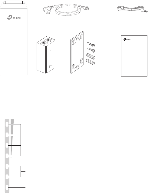
• Package Contents
Installation Guide
Outdoor CPE
CPE210 / CPE220 / CPE510 / CPE520
Pharos CPE Passive PoE
Adapter
Pole Mounting
Straps
Mounting Bracket
Plastic Wall Anchors (Qty.2)
Self-tapping Screws (Qty.2)
Installation Guide
Power Cord
• LED Explanation
The following picture takes CPE520 as an example.
POWERLAN0LAN1
AP/AP Router mode:
All four LEDs remain solid.
Client/Bridge/Repeater/AP Client Router mode:(Except CPE510)
That the more LEDs lit will indicate better wireless signal strength.
Flashing: A device is connected to this port, and is active.
On: The CPE is powered on.
On: A device is connected to this port, but there is no activity.
02
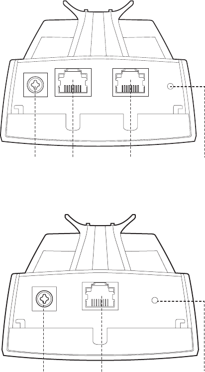
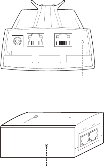
• Panel Layout
Pharos CPE220/CPE520:
Shielded Ethernet
Port LAN0 (Passive
PoE in)
RESETShielded Ethernet
Port LAN1
Grounding
Terminal
Pharos CPE210/CPE510:
Shielded Ethernet Port
LAN (Passive PoE in)
Grounding
Terminal
RESET
03
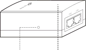
Passive PoE Adapter:
Remote Reset
Press and hold for 8 seconds to
reset the CPE to its factory defaults.
Power LED
The Power LED is on when the
passive PoE adapter is working
normally.
04
Hardware Connection
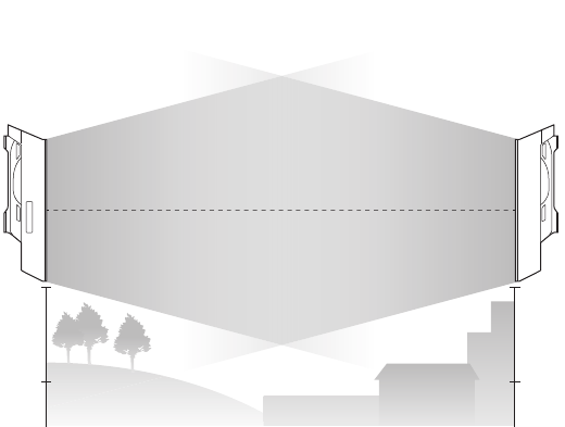
1. Site Consideration
• Mounting Height
Ensure a clear line of sight between the wireless devices for an optimum
performance. An elevated location is recommended as obstacles like
trees, buildings and large steel structures will weaken the wireless signal.
See 'Q2' in 'FAQ' for details about how to calculate the minimum mounting
height of the devices.
Line of Sight
Side View
05
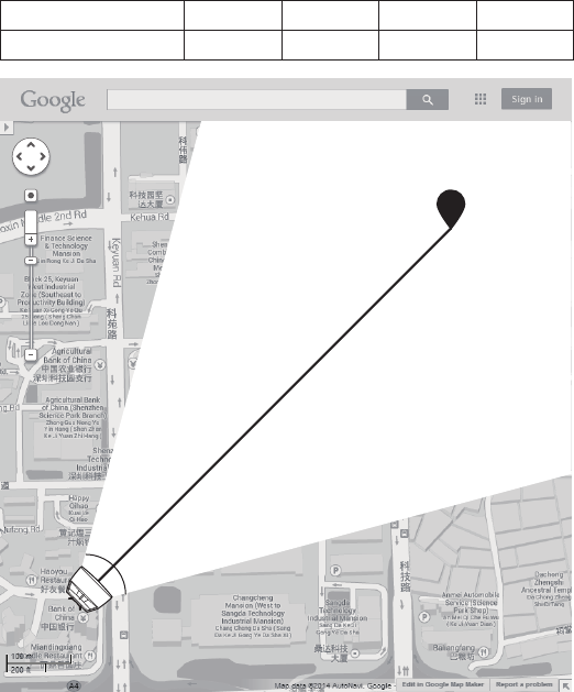
• Orientation
Install the CPE devices with the front facing the intended signal receiving
devices. You can orient the devices with the assistance of Google Maps,
GPS and some landmarks according to the horizontal beamwidth listed
below.
Models CPE210 CPE220 CPE510 CPE520
Horizontal Beamwidth 65° 60° 45° 45°
A
shenzhen
B
Line of Sight
Horizontal
Beamwidth
06
2. Connection and Installation
Connect and mount the CPE and power adapter as shown below. The
following introduction takes CPE520 as an example.
• Connecting CPE and Power Adapter
Connect the CPE and power adapter as shown in the gure below.
Ethernet cable length up to 60m
You should prepare an adequate
Ethernet cable to connect the CPE
and the passive PoE adapter.
Shielded CAT5e (or above) cable
with ground wire is recommended
(refer to the next section).
Connect to a computer,
router or switch.
(Depending on your
intended usage and/or
network topology.)
Slide to replace the cover
of the CPE when all
connections are nished.
LAN0
PoE LAN
07
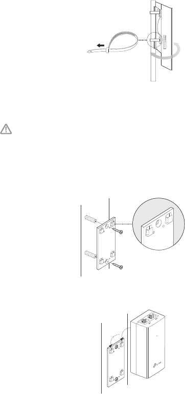
• Mounting CPE
At the selected site, approximately align the CPE to the direction that you
have oriented.
• Mounting Power Adapter (Optional)
Follow the steps below to mount the power adapter:
To ensure the passive PoE adapter is attached most securely, it is
recommended to install the adapter with the Ethernet port facing upward.
1. Drill two holes on the wall and insert the plastic wall anchors into the
the holes. Secure the mounting bracket to the wall. Make sure the
shoulders at the corners of the mounting bracket are on the outside
and pointing upward.
2. Attach the passive PoE adapter to the mounting bracket by sliding
the adapter in the direction of the arrows until it locks into place.
08
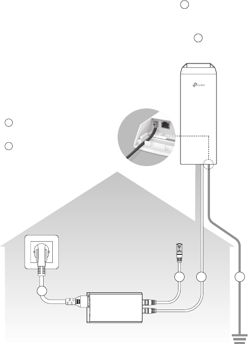
3. Lightning & ESD Protection
Proper grounding is extremely important for outdoor devices.
By using shielded CAT5e (or above) cable with ground wire for the
connection and the provided PoE adapter (method 1), you can eectively
eliminate ESD attacks. If you use the general CAT5e cable for the
connection, then it is necessary to connect the grounding terminal of the
CPE to earth ground through grounding cable (method 2).
The following introduction takes CPE520 as an example.
CPE
Grounding
Terminal
Earth Ground
Two Methods:
2
2
1
1
1
1
PoE Adapter with
Earth Ground
Grounding
Cable
Shielded CAT5e (or above) Cable
with Ground Wire
Grounding Terminal and Cable
Shielded CAT5e (or above)
Cable with Ground Wire
Grounded 3-wire
Power Outlet
09
Twisted Pair
Ground Wire
Shielded RJ45 Connector
Secondary Cable Shield
Cable Shield
Sheath
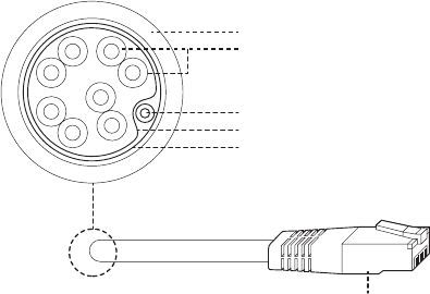
Shielded CAT5e (or above) Cable with Ground Wire
10
Software Conguration
This chapter introduces the login to the PharOS Web Interface and the
software congurations.
1. Logging in to the PharOS
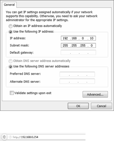
1. Before accessing the PharOS Web Interface, you need to assign
a static IP address 192.168.0.X (X ranges between 2 and 253, e.g.
192.168.0.10) to your computer.
2. Open a web browser, type http://192.168.0.254 into the address eld
and press Enter (Windows) or return (Mac). It is recommended to use
the latest version of Google Chrome, Firefox or Safari.

11
3. Enter admin for both User Name and Password. Read and agree the
terms of use, then click Login.
4. Change the default User Name and Password to protect your CPE.
Let’s start conguring the CPE.
For subsequent logins, use the new username and password.
For more congurations, please visit http://www.tp-link.com/support to
download the User Guide of PharOS products in the download center.
12
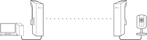
2. Typical Application Conguration
The typical topology is as follows. A wireless bridge is built between two
locations that are far from each other. Follow the instructions below to
congure the Access Point and the Client.
Access Point Client
Computer
IP camera
LAN: 192.168.0.254 LAN: 192.168.0.2
Congure the Access Point (AP)
1. Log in to PharOS and go to the Quick Setup page.
2. Operation Mode: Select Access Point and click Next.
3. LAN Settings: Click Next.
4. Wireless AP Settings:
a. Create a new SSID (Network name) for your wireless network.
b. Select WPA-PSK/WPA2-PSK for the Security method and create
a PSK Password to protect your AP.
c. Enter the distance between the Access Point and the Client into
the Distance Setting eld.
d. Select the MAXtream checkbox (Refer to Q3 in FAQ for details
about MAXtream), and click Next.
5. Finish: Verify your settings and click Finish to complete the
conguration.
Congure the Client
1. Log in to PharOS and go to the Quick Setup page.
2. Operation Mode: Select Client and click Next.
(except CPE510)
13
3. LAN Settings: Change the IP Address to 192.168.0.X (X ranges
between 2 and 253), the same subnet with the access point, and
click Next.
4. Wireless Client Settings:
a. Click Survey and select the SSID of the Access Point in the AP list,
then click Connect.
b. Select WPA-PSK/WPA2-PSK from the Security option, enter the
same PSK password and distance value of the Access Point, then
click Next.
5. Finish: Verify your settings and click Finish to complete the
conguration.
For more congurations, please visit http://www.tp-link.com/support to
download the User Guide of PharOS products in the download center.
14
Antenna Alignment
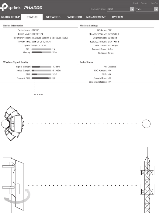
In order to get the best performance, you can precisely align the direction
of the CPE with the assistance of Wireless Signal Quality on
STATUS page of the PharOS Web Interface.
Adjust the direction of the CPE until the
device reaches the highest SNR.
WISP
WISP

14
Specications
HARDWARE FEATURES
Dimensions CPE520/CPE220: 275.83*79*60.3mm
CPE510/CPE210: 224.34*79*60.3mm
Interface
CPE520/CPE220 CPE510/CPE210
LAN0: 10/100Mbps
Ethernet Port(PoE IN)
LAN1: 10/100Mbps
Ethernet Port
LAN: 10/100Mbps
Ethernet Port(PoE IN)
GND: Grounding Terminal for Lightning Protection
RESET: Button to restore the device to Factory
Default
Power Supply 24V Passive PoE Adapter Included
ESD Protection115kV
Lightning Protection1Up to 6kV
Operating
Temperature
Operating Humidity 10% to 90 %
Certication CE, FCC, RoHS, IPX5
WIRELESS FEATURES
Models CPE210 CPE220 CPE510 CPE520
Antenna Gain 12dBi 13dBi 16dBi
Horizontal
Beamwidth/Elevation
Beamwidth2
65°/ 35° 60°/ 30° 45°/ 30° 45°/ 30°
802.11 Standards 11b/g/n 11b/g/n 11a/n 11a/n
Note:
1. Estimation is based on copper grounding cable and shielded CAT5e cable
with ground wire.
2. Beamwidth values may vary throughout operating frequency.
Carrier Sense
10.7dBi
CPE510: -40℃ to 70℃ (-22 ℉ to 158 ℉ )
16
FAQ
Q1. How to restore the CPE to its factory default
settings?
With the CPE powered on, press and hold the RESET button on the
CPE or the Remote Reset button on the passive PoE adapter for
about 8 seconds until the Wireless Signal Strength LEDs ash.
Method 1:
The following picture takes CPE520 as an example.
RESET Button
Press & hold for about 8
seconds
Method 2:
Remote Reset Button
Press & hold for about 8 seconds
17
Q2. How to calculate the minimum mounting height
of the devices?
In order to maximize the received signal strength of the devices,
installers need to minimize the eect of the out-of-phase signals,
which is caused by obstacles in the path between the transmitter
and the receiver. Fresnel Zone is a usual method to calculate this
path, as shown in the formula and the gure below.
h = the height of
obstacle at this point
H h+r*(1 40%)
(H is the height of the CPE)
d2
r
d1
where,
r = Fresnel zone radius in meters
c = 3x10⁸ m/s, speed of light
f = operating frequency of the devices in
Hz
d1 & d2 = the distances between the
point and the devices in meters
f
c
dd
dd
r⋅
+
×
=
21
21
For example, assume d1 is 2km, d2 is 8km, and f is 2.4GHz, then
r would be 14.142m. Considering a toleration of 40%, allowable
radius would be 8.485m. Assume h is 10m, then the result of the
minimum mounting height based on this point would be 18.485m.
Similarly, calculate the results based on all the points where there are
obstacles, and the maximum value would be the nal result.
For more information, please refer to:
http://en.wikipedia.org/wiki/Fresnel_zone
18
Q3. What is Pharos MAXtream?
Pharos MAXtream is a proprietary protocol developed on the basis
of Time Division Multiple Access (TDMA) by TP-Link.
The MAXtream technology has the following advantages:
• Eliminates hidden node collisions & improves channel eciency.
• Lower latency, higher throughput, larger network capacity &
more stability.
• Improves the QoS for video, voice and sound data stream.
By dividing the timing of transmission into dierent time slots,
MAXtream allows the Pharos devices to transmit in rapid
succession, one after another, each using its own time slot to
transmit and receive their own frames, which greatly reduces the
chance of collision.
Pharos MAXtream is a non-standard Wi-Fi protocol that is only
compatible with TP-Link’s Pharos series products. Please notice
that you will not be able to connect other Wi-Fi devices to an AP with
MAXtream enabled.
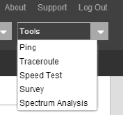
Q4. How can I use Spectrum Analysis to nd the
appropriate channel for the devices?
1. Log in to PharOS, click Spectrum Analysis in the tools drop-down
list, a window will pop up to remind you that all wireless connections
will be lost during spectrum analysis. Click Ye s to continue to the
Spectrum Analysis page.
2. Click Start, the PharOS will begin to analyze the power of
frequency. Observe the curves for a period of time, and then
click Stop. Note that the relatively low and continuous part of the
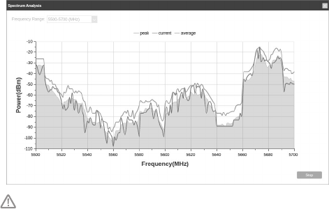
19
average curve indicates less radio noise. Here, we use the gure
below as an example.
The select box of Frequency Range at the top-left corner is only
available for CPE510 and CPE520. Select the desired range and
then click Start.
When choosing channel/frequency, you should avoid the spectrum
with large radio noise. In this example, the recommended channel/
frequency is 112/5560MHz.

FCC STATEMENT (For CPE220/CPE510/CPE520)
This equipment has been tested and found to comply with the limits for a Class A digital
device, pursuant to part 15 of the FCC Rules. These limits are designed to provide
reasonable protection against harmful interference when the equipment is operated
in a commercial environment. This equipment generates, uses, and can radiate radio
frequency energy and, if not installed and used in accordance with the instruction
manual, may cause harmful interference to radio communications. Operation of this
equipment in a residential area is likely to cause harmful interference in which case the
user will be required to correct the interference at his own expense.
This device complies with part 15 of the FCC Rules. Operation is subject to the following
two conditions:
1) This device may not cause harmful interference.
2) This device must accept any interference received, including interference that may
cause undesired operation.
Any changes or modifications not expressly approved by the party responsible for
compliance could void the user’s authority to operate the equipment.
Note: The manufacturer is not responsible for any radio or TV interference caused by
unauthorized modications to this equipment. Such modications could void the user’s
authority to operate the equipment.
(For CPE510)
This equipment has been tested and found to comply with the limits for a Class B digital
device, pursuant to part 15 of the FCC Rules. These limits are designed to provide
reasonable protection against harmful interference in a residential installation. This
equipment generates, uses and can radiate radio frequency energy and, if not installed
and used in accordance with the instructions, may cause harmful interference to radio
communications. However, there is no guarantee that interference will not occur in a
particular installation. If this equipment does cause harmful interference to radio or
television reception, which can be determined by turning the equipment o and on, the
user is encouraged to try to correct the interference by one or more of the following
measures:
• Reorient or relocate the receiving antenna.
• Increase the separation between the equipment and receiver.
• Connect the equipment into an outlet on a circuit different from that to which the
receiver is connected.
• Consult the dealer or an experienced radio/ TV technician for help.
This device complies with part 15 of the FCC Rules. Operation is subject to the following
two conditions:
1) This device may not cause harmful interference.
2) This device must accept any interference received, including interference that may
cause undesired operation.
Any changes or modifications not expressly approved by the party responsible for
compliance could void the user’s authority to operate the equipment.
Note: The manufacturer is not responsible for any radio or TV interference caused by
unauthorized modications to this equipment. Such modications could void the user’s
authority to operate the equipment.

FCC RF Radiation Exposure Statement:
This equipment complies with FCC RF radiation exposure limits set forth for an
uncontrolled environment. This device and its antenna must not be co-located or
operating in conjunction with any other antenna or transmitter.
“To comply with FCC RF exposure compliance requirements, this grant is applicable to
only Mobile Congurations. The antennas used for this transmitter must be installed to
provide a separation distance of at least 32 cm from all persons and must not be co-
located or operating in conjunction with any other antenna or transmitter.”
CE Mark Warning
For CPE220/CPE510/CPE520:
This is a Class A product. In a domestic environment, this product may cause radio
interference, in which case the user may be required to take adequate measures.
For CPE210:
This is a Class B product. In a domestic environment, this product may cause radio
interference, in which case the user may be required to take adequate measures.
OPERATING FREQUENCY(the maximum
transmitted power)
2412MHz—2472MHz(20dBm) (CPE210/CPE220)
5500MHz—5700MHz(27dBm) (CPE510/CPE520)
EU declaration of conformity
TP-Link hereby declares that the device is in compliance with the essential requirements
and other relevant provisions of directives 2014/53/EU, 2009/125/EC and 2011/65/EU.
The original EU declaration of conformity may be found at http://www.tp-link.com/en/ce
RF Exposure Information
This device meets the EU requirements (2014/53/EU Article 3.1a) on the limitation of
exposure of the general public to electromagnetic elds by way of health protection.
The device complies with RF specications when the device used at 20 cm from your
body.
Canadian Compliance Statement
This device complies with Industry Canada license-exempt RSSs. Operation is subject
to the following two conditions:
1) This device may not cause interference, and
2) This device must accept any interference, including interference that may cause
undesired operation of the device.
Le présent appareil est conforme aux CNR d’Industrie Canada applicables aux appareils
radio exempts de licence. L’exploitation est autorisée aux deux conditions suivantes :
1) l’appareil ne doit pas produire de brouillage;
2) l’utilisateur de l’appareil doit accepter tout brouillage radioélectrique subi, meme si le
brouillage est susceptible d’en compromettre le fonctionnement.
Caution: (For CPE510/CPE520)
1) The device for operation in the band 5150–5250 MHz is only for indoor use to reduce
the potential for harmful interference to co-channel mobile satellite systems;
2) For devices with detachable antenna(s), the maximum antenna gain permitted for
devices in the band 5725-5850 MHz shall be such that the equipment still complies
with the e.i.r.p. limits specied for point-to-point and non-point-to-point operation as
appropriate; and
The high-power radars are allocated as primary users (i.e. priority users) of the bands
5250-5350 MHz and 5650-5850 MHz and that these radars could cause interference
and/or damage to LE-LAN devices.
Avertissement: (For CPE510/CPE520)
1) Le dispositif fonctionnant dans la bande 5150-5250 MHz est réservé uniquement
pour une utilisation à l’intérieur an de réduire les risques de brouillage préjudiciable
aux systèmes de satellites mobiles utilisant les mêmes canaux;
2) Le gain maximal d'antenne permis pour les dispositifs avec antenne(s) amovible(s)
utilisant la bande 5725-5850 MHz doit se conformer à la limitation P.I.R.E spéciée
pour l’exploitation point à point et non point à point, selon le cas.
En outre, les utilisateurs devraient aussi être avisés que les utilisateurs de radars de
haute puissance sont désignés utilisateurs principaux (c.-à-d., qu’ils ont la priorité) pour
les bandes 5250-5350 MHz et 5650-5850 MHz et que ces radars pourraient causer du
brouillage et/ou des dommages aux dispositifs LAN-EL.
Industry Canada Statement (For CPE220/CPE510/CPE520)
CAN ICES-3 (A)/NMB-3(A)
Industry Canada Statement (For CPE210)
CAN ICES-3 (B)/NMB-3(B)

Safety Information
• Keep the device away from water, re, humidity or hot environments.
• Do not attempt to disassemble, repair, or modify the device.
• Do not use damaged charger or USB cable to charge the device.
• Do not use any other chargers than those recommended
• Do not use the device where wireless devices are not allowed.
• Adapter shall be installed near the equipment and shall be easily accessible.
Use only power supplies which are provided by manufacturer and in the original
packing of this product. If you have any questions, please don't hesitate to contact us.
Please read and follow the above safety information when operating the device. We
cannot guarantee that no accidents or damage will occur due to improper use of the
device. Please use this product with care and operate at your own risk.
NCC Notice & BSMI Notice
注意!
依據 低功率電波輻射性電機管理辦法
第十二條 經型式認證合格之低功率射頻電機,非經許可,公司、商號或使用者均不得擅
自變更頻率、加大功率或變更原設計之特性或功能。
第十四條 低功率射頻電機之使用不得影響飛航安全及干擾合法通行;經發現有干擾現象
時,應立即停用,並改善至無干擾時方得繼續使用。前項合法通信,指依電信規定作業
之無線電信。低功率射頻電機需忍受合法通信或工業、科學以及醫療用電波輻射性電機
設備之干擾。
安全諮詢及注意事項
• 請使用原裝電源供應器或只能按照本產品注明的電源類型使用本產品。
• 清潔本產品之前請先拔掉電源線。請勿使用液體、噴霧清潔劑或濕布進行清潔。
• 注意防潮,請勿將水或其他液體潑灑到本產品上。
• 插槽與開口供通風使用,以確保本產品的操作可靠並防止過熱,請勿堵塞或覆蓋開口。
• 請勿將本產品置放於靠近熱源的地方。除非有正常的通風,否則不可放在密閉位置中。
• 請不要私自打開機殼,不要嘗試自行維修本產品,請由授權的專業人士進行此項工作。
(For CPE220/CPE510/CPE520) 此為甲類資訊技術設備,于居住環境中使用時,可能會
造成射頻擾動,在此種情況下,使用者會被要求採取某些適當的對策
Продукт сертифіковано згідно с правилами системи УкрСЕПРО на відповідність
вимогам нормативних документів та вимогам, що передбачені чинними
законодавчими актами України.
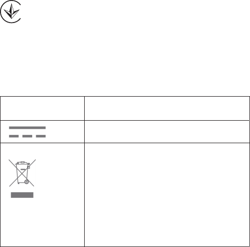
Explanation of the symbols on the product label
Symbol Explanation
DC voltage
RECYCLING
This product bears the selective sorting symbol for
Waste electrical and electronic equipment (WEEE).
This means that this product must be handled
pursuant to European directive 2012/19/EU in order
to be recycled or dismantled to minimize its impact
on the environment.
User has the choice to give his product to a
competent recycling organization or to the retailer
when he buys a new electrical or electronic
equipment.
(For CPE220/CPE510/CPE520)
この装置は、クラスA情報技術装置です。この装置を家庭環境で使用すると電波妨害を
引き起こすことがあります。この場合には使用者が適切な対策を講ずるよう要求され
ることがあります。 VCCI-A