TP Link Technologies CR700V1 AC1750 Wireless Dual Band DOCSIS 3.0 Cable Modem Router User Manual
TP-Link Technologies Co., Ltd. AC1750 Wireless Dual Band DOCSIS 3.0 Cable Modem Router
User Manual
Archer CR700
AC1750 Wireless Dual Band Gigabit DOCSIS 3.0 Cable Modem
Router

COPYRIGHT & TRADEMARKS
Specifications are subject to change without notice. is a registered trademark of
TP-LINK TECHNOLOGIES CO., LTD. Other brands and product names are trademarks or
registered trademarks of their respective holders.
No part of the specifications may be reproduced in any form or by any means or used to make any
derivative such as translation, transformation, or adaptation without permission from TP-LINK
TECHNOLOGIES CO., LTD. Copyright © 2014 TP-LINK TECHNOLOGIES CO., LTD. All rights
reserved.
http://www.tp-link.com

FCC STATEMENT
This equipment has been tested and found to comply with the limits for a Class B digital device,
pursuant to part 15 of the FCC Rules. These limits are designed to provide reasonable protection
against harmful interference in a residential installation. This equipment generates, uses and can
radiate radio frequency energy and, if not installed and used in accordance with the instructions,
may cause harmful interference to radio communications. However, there is no guarantee that
interference will not occur in a particular installation. If this equipment does cause harmful
interference to radio or television reception, which can be determined by turning the equipment off
and on, the user is encouraged to try to correct the interference by one or more of the following
measures:
• Reorient or relocate the receiving antenna.
• Increase the separation between the equipment and receiver.
• Connect the equipment into an outlet on a circuit different from that to which the receiver
is connected.
• Consult the dealer or an experienced radio/ TV technician for help.
This device complies with part 15 of the FCC Rules. Operation is subject to the following two
conditions:
1) This device may not cause harmful interference.
2) This device must accept any interference received, including interference that may cause
undesired operation.
Any changes or modifications not expressly approved by the party responsible for compliance
could void the user’s authority to operate the equipment.
Note: The manufacturer is not responsible for any radio or TV interference caused by
unauthorized modifications to this equipment. Such modifications could void the user’s authority to
operate the equipment.
FCC RF Radiation Exposure Statement
This equipment complies with FCC RF radiation exposure limits set forth for an uncontrolled
environment. This device and its antenna must not be co-located or operating in conjunction with
any other antenna or transmitter.
“To comply with FCC RF exposure compliance requirements, this grant is applicable to only
Mobile Configurations. The antennas used for this transmitter must be installed to provide a
separation distance of at least 20 cm from all persons and must not be co-located or operating in
conjunction with any other antenna or transmitter.”
The device is restricted to indoor use only.
CE Mark Warning

This is a class B product. In a domestic environment, this product may cause radio interference, in
which case the user may be required to take adequate measures.
National Restrictions
This device is intended for home and office use in all EU countries (and other countries following
the EU directive 1999/5/EC) without any limitation except for the countries mentioned below:
Country Restriction Reason/remark
Bulgaria None General authorization required for outdoor use and
public service
France
Outdoor use limited to 10
mW e.i.r.p. within the band
2454-2483.5 MHz
Military Radiolocation use. Refarming of the 2.4 GHz
band has been ongoing in recent years to allow current
relaxed regulation. Full implementation planned 2012
Italy None If used outside of own premises, general authorization is
required
Luxembourg None General authorization required for network and service
supply(not for spectrum)
Norway Implemented This subsection does not apply for the geographical area
within a radius of 20 km from the centre of Ny-Ålesund
Russian Federation None Only for indoor applications
Note: Please don’t use the product outdoors in France.
Canadian Compliance Statement
This device complies with Industry Canada license-exempt RSS standard(s). Operation is subject
to the following two conditions:
(1)This device may not cause interference, and
(2)This device must accept any interference, including interference that may cause undesired
operation of the device.
Cet appareil est conforme aux norms CNR exemptes de licence d’Industrie Canada. Le
fonctionnement est soumis aux deux conditions suivantes:
(1)cet appareil ne doit pas provoquer d’interférences et
(2)cet appareil doit accepter toute interférence, y compris celles susceptibles de provoquer un
fonctionnement non souhaité de l’appareil.
Industry Canada Statement
Complies with the Canadian ICES-003 Class B specifications.
Cet appareil numérique de la classe B est conforme à la norme NMB-003 du Canada.
This device complies with RSS 210 of Industry Canada. This Class B device meets all the
requirements of the Canadian interference-causing equipment regulations.

Cet appareil numérique de la Classe B respecte toutes les exigences du Règlement sur le
matériel brouilleur du Canada.
Korea Warning Statements:
당해 무선설비는 운용중 전파혼신 가능성이 있음.
NCC Notice& BSMI Notice:
注意!
依據 低功率電波輻射性電機管理辦法
第十二條 經型式認證合格之低功率射頻電機,非經許可,公司、商號或使用者均不得擅自變更頻率、
加大功率或變更原設計之特性或功能。
第十四條 低功率射頻電機之使用不得影響飛航安全及干擾合法通行;經發現有干擾現象時,應立即
停用,並改善至無干擾時方得繼續使用。前項合法通信,指依電信規定作業之無線電信。低功率射
頻電機需忍受合法通信或工業、科學以及醫療用電波輻射性電機設備之干擾。
減少電磁波影響,請妥適使用。
安全諮詢及注意事項
●請使用原裝電源供應器或只能按照本產品注明的電源類型使用本產品。
●清潔本產品之前請先拔掉電源線。請勿使用液體、噴霧清潔劑或濕布進行清潔。
●注意防潮,請勿將水或其他液體潑灑到本產品上。
●插槽與開口供通風使用,以確保本產品的操作可靠並防止過熱,請勿堵塞或覆蓋開口。
●請勿將本產品置放於靠近熱源的地方。除非有正常的通風,否則不可放在密閉位置中。
●請不要私自打開機殼,不要嘗試自行維修本產品,請由授權的專業人士進行此項工作。
Продукт сертифіковано згідно с правилами системи УкрСЕПРО на відповідність вимогам
нормативних документів та вимогам, що передбачені чинними законодавчими актами
України.
Safety Information
z When product has power button, the power button is one of the way to shut off the product;
when there is no power button, the only way to completely shut off power is to disconnect the
product or the power adapter from the power source.
z Don’t disassemble the product, or make repairs yourself. You run the risk of electric shock
and voiding the limited warranty. If you need service, please contact us.

z Avoid water and wet locations.
This product can be used in the following countries:
AT BG BY CA CZ DE DK EE
ES FI FR GB GR HU IE IT
LT LV MT NL NO PL PT RO
RU SE SK TR UA

TP-LINK TECHNOLOGIES CO., LTD
TP-LINK TECHNOLOGIES CO., LTD
Building 24 (floors 1, 3, 4, 5), and 28 (floors 1-4) Central Science and Technology Park,
Shennan Rd, Nanshan, Shenzhen, China
DECLARATION OF CONFORMITY
For the following equipment:
Product Description: AC1750 Wireless Dual Band Gigabit DOCSIS 3.0 Cable Modem Router
Model No.: Archer CR700
Trademark: TP-LINK
We declare under our own responsibility that the above products satisfy all the technical
regulations applicable to the product within the scope of Council Directives:
Directives 1999/5/EC, Directives 2004/108/EC, Directives 2006/95/EC, Directives 1999/519/EC,
Directives 2011/65/EU
The above product is in conformity with the following standards or other normative documents
EN 300 328 V1.7.1: 2006
EN 301 489-1 V1.9.2:2011& EN 301 489-17 V2.2.1:2012
EN 55022:2010
EN 55024:2010
EN 61000-3-2:2006+A1:2009+A2:2009
EN 61000-3-3:2008
EN60950-1:2006+A11:2009+A1:2010+A12:2011
EN62311:2008
EN 301 893
The product carries the CE Mark:
Person responsible for making this declaration:
Yang Hongliang
Product Manager of International Business
Date of issue: 2014
CONTENTS
Chapter 1. Product Overview...................................................................................1
1.1 Overview of the Modem Router ...................................................................................... 1
1.2 Main Features................................................................................................................. 2
1.3 Panel Layout...................................................................................................................3
1.3.1 The Front Panel ................................................................................................................... 3
1.3.2 The Back Panel.................................................................................................................... 4
Chapter 2. Connecting the Modem Router .............................................................6
2.1 System Requirements .................................................................................................... 6
2.2 Installation Environment Requirements .......................................................................... 6
2.3 Connecting the Modem Router.......................................................................................6
2.4 Test Your Internet Connection........................................................................................ 7
Chapter 3. Configuring the Modem Router ............................................................8
3.1 Login ............................................................................................................................... 8
3.2 Status.............................................................................................................................. 8
3.3 Basic ............................................................................................................................... 9
3.3.1 Setup.................................................................................................................................. 10
3.3.2 DHCP ................................................................................................................................. 10
3.3.3 DHCPv6 ............................................................................................................................. 11
3.3.4 LAN IPv6 ............................................................................................................................ 12
3.3.5 DDNS ................................................................................................................................. 12
3.3.6 Backup ............................................................................................................................... 13
3.3.7 Upgrade ............................................................................................................................. 13
3.3.8 Reboot................................................................................................................................ 14
3.3.9 Reset.................................................................................................................................. 14
3.4 Advanced...................................................................................................................... 15
3.4.1 Options............................................................................................................................... 15
3.4.2 IP Filtering.......................................................................................................................... 16
3.4.3 MAC Filtering ..................................................................................................................... 16
3.4.4 Port Filtering....................................................................................................................... 16
3.4.5 Forwarding ......................................................................................................................... 17
3.4.6 Port Triggers ...................................................................................................................... 17
3.4.7 DMZ Host........................................................................................................................... 18
3.4.8 RIP Setup........................................................................................................................... 18
3.5 Firewall ......................................................................................................................... 19
3.5.1 Basic .................................................................................................................................. 19
3.5.2 Local Log............................................................................................................................ 19
3.5.3 Remote Log........................................................................................................................ 20
3.6 Parental Control............................................................................................................ 20
3.6.1 Basic Setup ........................................................................................................................ 20
3.6.2 User Setup ......................................................................................................................... 21
3.6.3 ToD Filter ........................................................................................................................... 22
3.6.4 Event Log........................................................................................................................... 23
3.7 VPN .............................................................................................................................. 23
3.7.1 Basic .................................................................................................................................. 23
3.7.2 IPsec .................................................................................................................................. 23
3.7.3 Event Log........................................................................................................................... 25
3.8 Wireless 2.4GHz........................................................................................................... 25
3.8.1 Basic .................................................................................................................................. 26
3.8.2 Primary Network.................................................................................................................26
3.8.3 Guest Network ...................................................................................................................27
3.8.4 Advanced ........................................................................................................................... 27
3.8.5 Bridging .............................................................................................................................. 28
3.8.6 Access Control................................................................................................................... 28
3.9 Wireless 5GHz.............................................................................................................. 28
3.9.1 Basic .................................................................................................................................. 29
3.9.2 Primary Network.................................................................................................................29
3.9.3 Guest Network ...................................................................................................................30
This page allows configuration of a guest network...................................................................... 30
3.9.4 Advanced ........................................................................................................................... 30
3.9.5 Bridging .............................................................................................................................. 30
3.9.6 Access Control................................................................................................................... 31
3.10 USB Settings ................................................................................................................ 31
3.10.1 Approved Devices ............................................................................................................ 31
3.10.2 User Accounts .................................................................................................................. 32
3.10.3 Storage Sharing................................................................................................................ 33
3.10.4 FTP Server ....................................................................................................................... 34
3.10.5 Media Server ....................................................................................................................36
3.11 Logout........................................................................................................................... 37

Archer CR700 User Guide
1
Chapter 1. Product Overview
Thank you for choosing the Archer CR700 AC1750 Wireless Dual Band Gigabit DOCSIS 3.0
Cable Modem Router.
1.1 Overview of the Modem Router
The Archer CR700 AC1750 Wireless Dual Band Gigabit DOCSIS 3.0 Cable Modem Router
integrates DOCSIS 3.0 modem, NAT router, 4-port switch and wireless access point in one device
provides a one-stop networking solution.
The modem router provides up to 450Mbps (2.4GHz) + 1300Mbps (5GHz) wireless connection with
other wireless clients. The incredible speed makes it ideal for handling multiple data streams at the
same time, which ensures your network stable and smooth. The performance of this 802.11ac
wireless modem router will give you the unexpected networking experience at speed much faster than
802.11n. It is also compatible with all IEEE 802.11a, IEEE 802.11b, IEEE 802.11g and IEEE 802.11n,
products.
With multiple protection measures, including SSID broadcast control and wireless LAN 64/128
WEP encryption, Wi-Fi protected Access (WPA2-PSK, WPA-PSK), as well as advanced Firewall
protections, the Archer CR700 AC1750 Wireless Dual Band Gigabit DOCSIS 3.0 Cable Modem
Router provides complete data privacy.
The modem router provides flexible access control, so that parents or network administrators can
establish restricted access policies for children or staffs. It also supports Virtual Server and DMZ
host for Port Triggering, and then the network administrators can manage and monitor the network
in real time with the remote management function.
Since the modem router is compatible with virtually all the major operating systems, it is very easy
to manage. Detailed instructions are provided step by step in this user guide. Before installing the
modem router, please look through this guide to know all the modem router’s functions.

Archer CR700 User Guide
2
1.2 Main Features
¾ Supports 802.11ac - The next generation of Wi-Fi
¾ Dual band – for combined wireless speeds of up to 1.75Gbps at 2.4GHz and 5GHz band
concurrently
¾ DOCSIS 3.0/EuroDOCSIS 3.0, Compatible with DOCSIS/EuroDOCSIS 2.0/1.1/1.0
¾ 16 Downstream Channel bonding, Up to 680Mbps Downstream for DOCSIS and 900Mbps for
EuroDOCSIS
¾ 4 Upstream Channel bonding, Up to 120Mbps Upstream
¾ Full Band Capture windows - Utilize any channels in the downstream spectrum.
¾ Dual-core processor –for wonderful performance with Internet, Wi-Fi, Ethernet and USB
devices
¾ 6internal antennas provide maximum Omni-directional wireless coverage and reliability
¾ Full gigabit ports ensure ultra fast data transfer speeds
¾ Dual USB Ports - easily share printers, files or media with your friends or family locally or over
the Internet
¾ Guest Network Access provides secure Wi-Fi access for guests sharing your home or office
network
¾ IPv6 supported, meeting the demands for the next generation of Internet
¾ Wi-Fi On/Off Button allows users to turn their wireless radio on or off
¾ Easy one-touch WPA wireless security encryption with the WPS button
¾ WPA-PSK/WPA2-PSK encryptions provide user networks with active defense against
security threats
¾ Parental Controls allow parents or administrators to establish restricted access policies for
children or staff
¾ Wireless Schedule lets you to turn the Wi-Fi radio on or off based on a preset timetable.
¾ VPN Support —Access to your Home Network and Office Network securely
¾ Powerful Remote Management – Support SNMP v1 /v2 /v3 and TR-069 for remote
management
Archer CR700 User Guide
3
1.3 Panel Layout
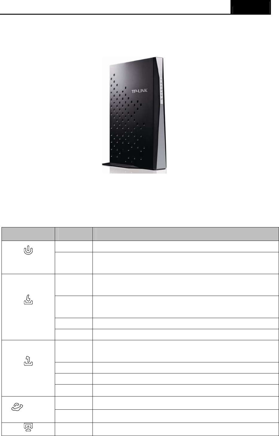
1.3.1 The Front Panel
Figure 1-1
The modem router’s LEDs are located on the side panel (View from top to bottom). They indicate
the device’s working status. For details, please refer to LED Explanation.
LED Explanation:
Name Status Indication
On The modem router is powered on.
(Power) Off The modem router is off. Please ensure that the power adapter is
connected correctly.
Orange The modem router is synchronized to multiple downstream
channels.
White The modem router is synchronized to a single downstream
channel.
Flash Scanning for a downstream channel connection.
(Downstream)
Off Failed to search non-bounded downstream channel.
Orange The modem router is synchronized to multiple upstream
channels.
White The modem router is synchronized to a single upstream channel.
Flash Scanning for an upstream channel connection.
(Upstream)
Off Failed to search non-bounded upstream channel.
On The network is available with a successful Internet connection.
(Online) Off There is no successful Internet connection.
On There is a device connected to this LAN port.
Archer CR700 User Guide
4
(LAN) Off There is no device connected to this LAN port.
On Wireless is enabled. The modem router is working on 2.4GHz/5
GHz radio band.
(Wireless) Off Wireless is disabled.
On A wireless device has been successfully added to the network by
WPS function.
Flash
WPS handshaking is in process and will continue for about 2
minutes. Please press the WPS button on other wireless devices
that you want to add to the network while the LED is flashing.
(WPS)
Off A wireless device has failed to be added to the network by WPS
function.
Off No storage device or printer is plugged into the USB port. (USB on the
back panel) On A storage device or printer has connected to the USB port.
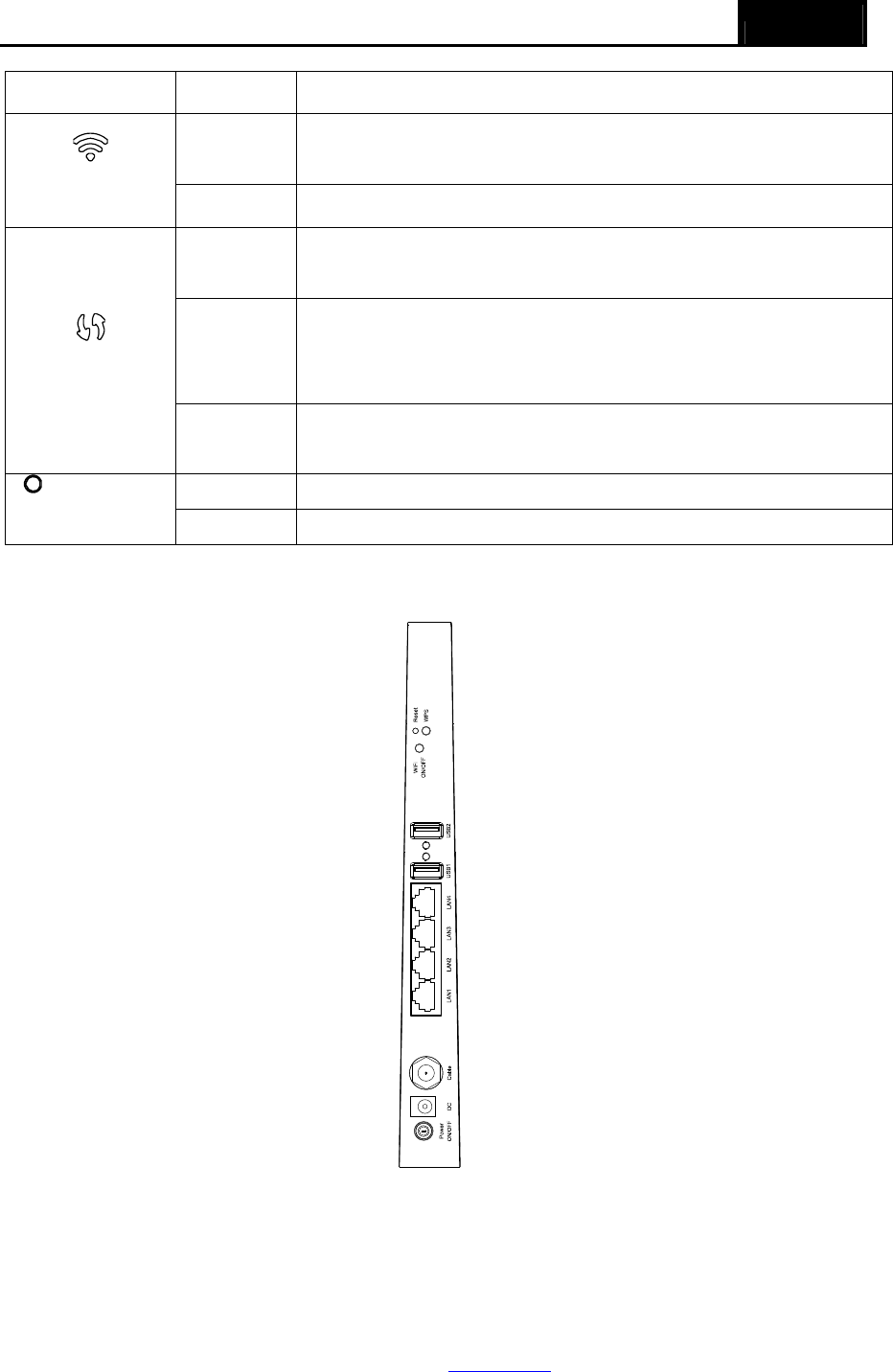
1.3.2 The Back Panel
Figure 1-2
¾ RESET: There are two ways to reset the modem router's factory defaults.
Method one: With the modem router powered on, use a pin to press and hold the Reset
button for at least 8-10 seconds. And the modem router will reboot to its factory default
settings.
Method two: Restore the default setting from “3.3.9 Reset” of the modem router's Web-based
Management.

Archer CR700 User Guide
5
¾ WPS: The switch for the WPS function.
¾ WiFi ON/OFF: The switch for the WiFi function. Press it to enable/disable the WiFi function.
¾ USB2, USB1: The USB port connects to a USB storage device or a USB printer.
¾ LAN4/WAN, LAN3, LAN2, LAN1: Through these ports, you can connect the modem router to
your PC or the other Ethernet network devices.
¾ Cable:
¾ DC: The power plug where you will connect the power adapter.
¾ Power ON/OFF: The switch for the power.

Archer CR700 User Guide
6
Chapter 2. Connecting the Modem Router
2.1 System Requirements
¾ Broadband Internet Access Service (DSL/Cable/Ethernet).
¾ PCs with a working Ethernet Adapter and an Ethernet cable with RJ45 connectors.
¾ TCP/IP protocol on each PC.
¾ Web browser, such as Microsoft Internet Explorer, Mozilla Firefox or Apple Safari.
2.2 Installation Environment Requirements
¾ The Product should not be located where it will be exposed to moisture or excessive heat.
¾ Place the Router in a location where it can be connected to the various devices as well as to a
power source.
¾ Make sure the cables and power cord are safely placed out of the way so they do not create a
tripping hazard.
¾ The Router can be placed on a shelf or desktop.
¾ Keep away from the strong electromagnetic radiation and the device of electromagnetic
sensitive.
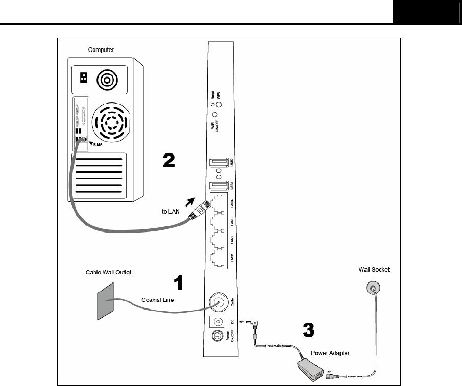
2.3 Connecting the Modem Router
Before installing the device, please make sure your broadband cable service provided by your ISP
is available. If there is any problem, please contact your ISP. Before cable connection, cut off the
power supply and keep your hands dry. You can follow the steps below to install it.
Step 1: Connect the coaxial line. Plug one end of the coaxial line into the Cable port on the rear
panel of Archer CR700, and insert the other end into the cable wall outlet.
Step 2: Connect the Ethernet cable. Attach one end of a network cable to your computer’s
Ethernet port or a regular hub/switch port, and the other end to the LAN port on the
modem router Archer CR700.
Step 3: Attach the power adapter. Connect the power adapter to the power connector on the rear
of the device and plug in the adapter to an electrical outlet or power extension. The
electrical outlet shall be installed near the device and shall be easily accessible.
Step 4: Power on the computers and LAN devices.
Archer CR700 User Guide
7
Figure 2-1
2.4 Test Your Internet Connection
Please open the web browser and try to log on to http://www.tp-link.com to test your Internet
connection.
Archer CR700 User Guide
8
Chapter 3. Configuring the Modem Router
This chapter will show configuration for the key functions on the Web-based management page.
3.1 Login
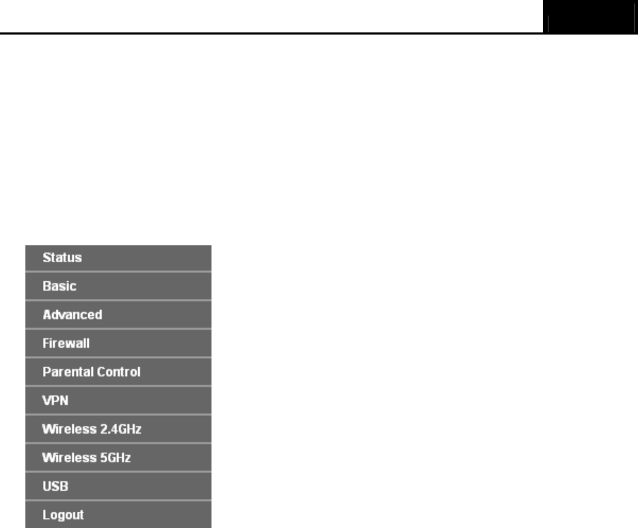
After your successful login, you will see the ten main menus on the left of the Web-based
management page. On the right, there are the corresponding explanations and instructions.
The detailed explanations for each Web page’s key function are listed below.
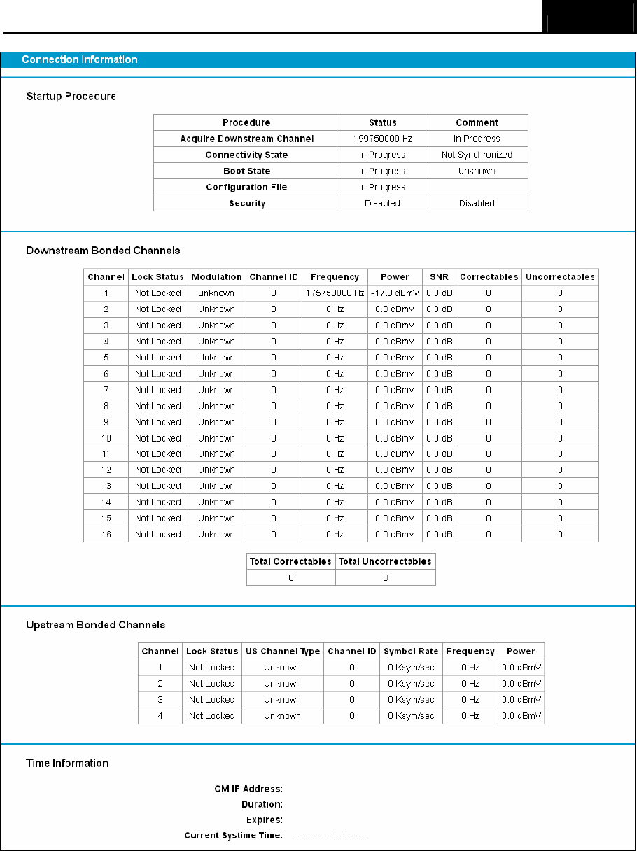
3.2 Status
Choose “Status”, you can see the corresponding information about Startup Procedure,
Downstream Bonded Channels, Upstream Bonded Channels and Time Information.
Archer CR700 User Guide
9
Figure 3-1
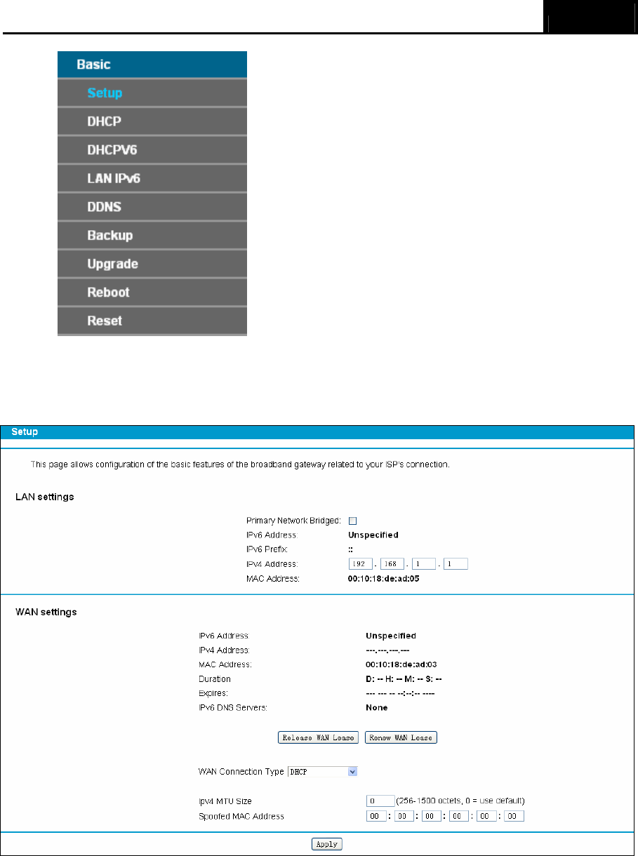
3.3 Basic
Choose “Basic”, there are many submenus under the main menu. Click any one of them, and you
will be able to configure the corresponding function.
Archer CR700 User Guide
10
3.3.1 Setup
Choose “Basic”Æ“Setup”, and you will be able to configure LAN and WAN settings related to your
ISP's connection.
Figure 3-2
After you finish the configuration, please click Save to make the settings take effect.
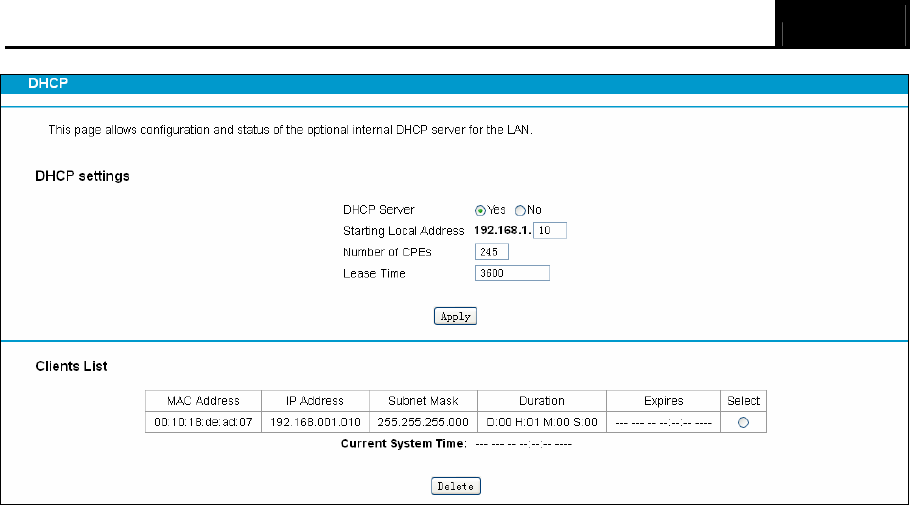
3.3.2 DHCP
Choose menu “Basic”Æ“DHCP”, you can configure the DHCP Server on the page as shown in
Figure 3-3.The modem router is set up by default as a DHCP (Dynamic Host Configuration
Protocol) server, which provides the TCP/IP configuration for all the PC(s) that are connected to
the modem router on the LAN.
Archer CR700 User Guide
11
Figure 3-3
¾ Lease Time: The Leased Time is the amount of time in which a network user will be allowed
connection to the modem router with their current dynamic IP address. Enter the amount of
time, in hours, then the user will be “leased” this dynamic IP address. After the dynamic IP
address has expired, the user will be automatically assigned a new dynamic IP address. The
default is 3600 minutes.
Click the Apply button to save your settings.
¾ Clients List:Display the information about the clients attached to the modem router.
¾ MAC Address: The MAC address of the DHCP client
¾ IP Address: The IP address that the modem router has allocated to the DHCP client
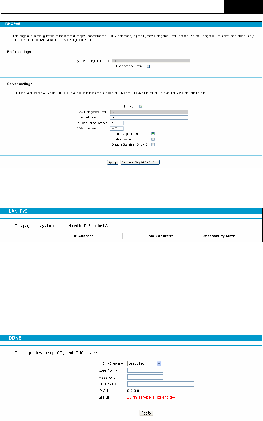
3.3.3 DHCPv6
Choose menu “Basic”Æ“DHCPv6”, you can configure the DHCPv6 Server on the page as shown
in Figure 3-4.
Archer CR700 User Guide
12
Figure 3-4
3.3.4 LAN IPv6
Choose “Basic”Æ“LAN IPv6” menu, and you will see the LAN screen (shown in Figure 3-5).
Figure 3-5
3.3.5 DDNS
Choose “Basic”Æ“DDNS” and you can configure the Dynamic DNS function.
The modem router offers the DDNS (Dynamic Domain Name System) feature, which allows the
hosting of a website, FTP server, or e-mail server with a fixed domain name (named by yourself)
and a dynamic IP address, then your friends can connect to your server by entering your domain
name no matter what your IP address is. Before using this feature, you need to sign up for DDNS
service providers such as www.no-ip.com. The Dynamic DNS client service provider will give you
a password or key.
Archer CR700 User Guide
13
Figure 3-6
¾ Service Provider: This field displays the service provider of DDNS.
¾ Username & Password: Type the “User Name” and “Password” for your DDNS account.
¾ Login/ Logout: Login to or logout of the DDNS service.
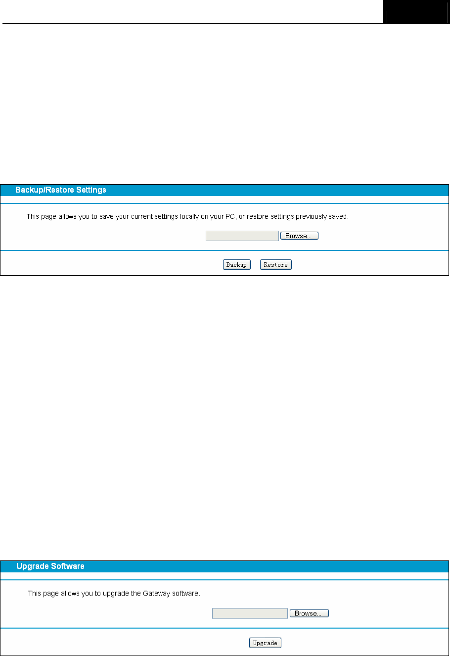
3.3.6 Backup
Choose menu “Basic” → “Backup e”, and then you can save the current configuration of the
modem router as a backup file and restore the configuration via a backup file as shown in Figure
3-7.
Figure 3-7
¾ Click the Backup button to save all configuration settings as a backup file in your local
computer.
¾ To upgrade the modem router’s configuration, follow these instructions.
• Click the Browse button to find the configuration file which you want to restore.
• Click the Restore button to update the configuration with the file whose path is the one
you have input or selected in the blank.
) Note:
The current configuration will be covered with the uploading configuration file. Wrong process will
lead the device unmanaged. The restoring process lasts for 20 seconds and the modem router will
restart automatically then. Keep the power of the modem router on during the process, in case of
any damage.
3.3.7 Upgrade
Choose menu “Basic →Upgrade”, and then you can update the latest version of firmware for the
modem router on the following screen.
Figure 3-8
To upgrade the modem router's firmware, follow these instructions below:
1) Download a most recent firmware upgrade file from our website (www.tp-link.com).
Archer CR700 User Guide
14
2) Click Browse to select the path name where you save the downloaded file on the computer
into the File Name blank.
3) Click the Upgrade button.
4) The modem router will reboot while the upgrading has been finished.
) Note:
1) New firmware versions are posted at http://www.tp-link.com and can be downloaded for free.
There is no need to upgrade the firmware unless the new firmware has a new feature you
want to use. However, when experiencing problems caused by the modem router rather than
the configuration, you can try to upgrade the firmware.
2) When you upgrade the modem router's firmware, you may lose its current configurations, so
before upgrading the firmware please write down some of your customized settings to avoid
losing important settings.
3) Do not turn off the modem router or press the Reset button while the firmware is being
upgraded. Loss of power during the upgrade could damage the modem router.
4) The firmware version must correspond to the hardware.
5) The upgrade process takes a few moments and the modem router restarts automatically
when the upgrade is complete.
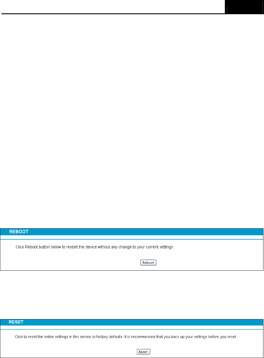
3.3.8 Reboot
Choose menu “Basic” → “Reboot”, and then you can click the Reboot button to reboot the
modem router.
Figure 3-9
3.3.9 Reset
Choose menu “Basic → Reset”, and then and you can restore the configurations of the modem
router to factory defaults.
Figure 3-10
Click the Restore button to reset all configuration settings to their default values.
• The default Username: admin
• The default Password: admin
• The default Subnet Mask: 255.255.255.0
Archer CR700 User Guide
15
) Note:
All changed settings will be lost when defaults are restored.
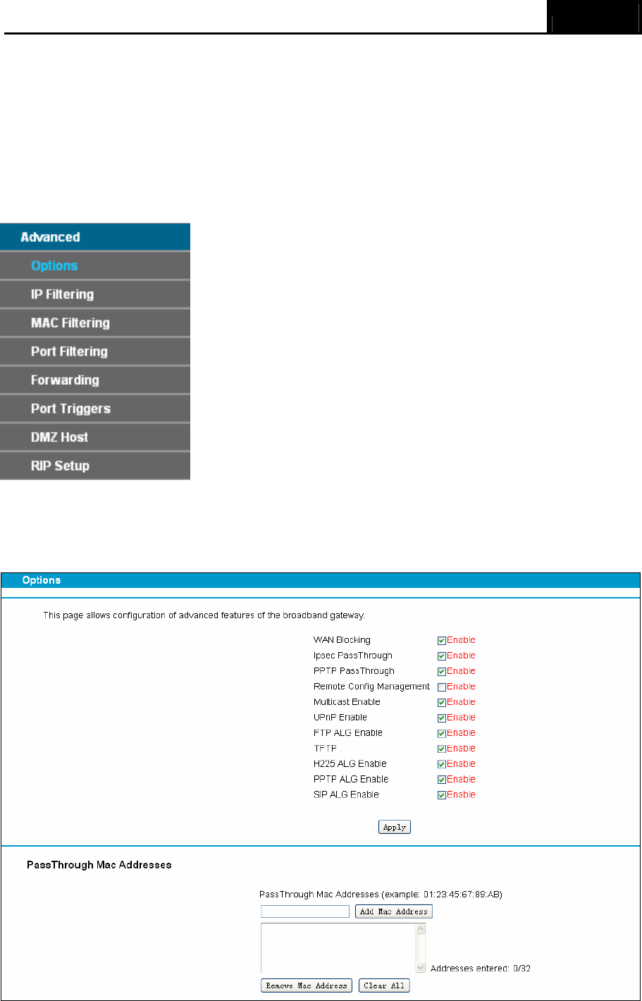
3.4 Advanced
Choose “Advanced”, there are many submenus under the main menu. Click any one of them, and
you will be able to configure the corresponding function.
3.4.1 Options
This page allows configuration of advanced features of the broadband gateway.
Figure 3-11
Archer CR700 User Guide
16
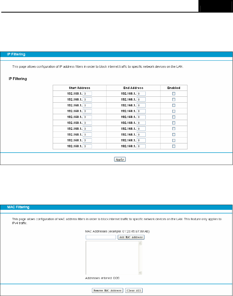
3.4.2 IP Filtering
This page allows configuration of IP address filters in order to block internet traffic to specific
network devices on the LAN.
Figure 3-12
3.4.3 MAC Filtering
This page allows configuration of MAC address filters in order to block internet traffic to specific
network devices on the LAN. This feature only applies to IPv4 traffic.
Figure 3-13
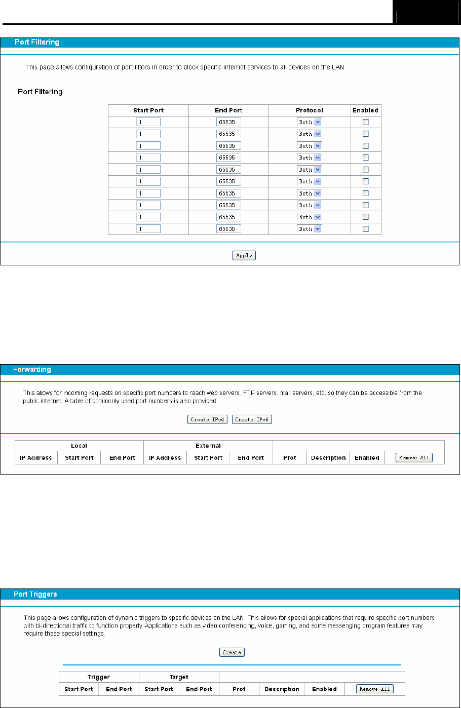
3.4.4 Port Filtering
This page allows configuration of port filters in order to block specific internet services to all
devices on the LAN.
Archer CR700 User Guide
17
Figure 3-14
3.4.5 Forwarding
This allows for incoming requests on specific port numbers to reach web servers, FTP servers,
mail servers, etc. so they can be accessible from the public internet. A table of commonly used
port numbers is also provided.
Figure 3-15
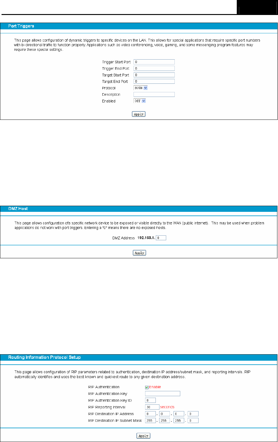
3.4.6 Port Triggers
Choose menu “Advanced”→ ”Port Triggers”, you can view and add port trigger in the screen as
shown in Figure 3-16. Some applications require multiple connections, like Internet games, video
conferencing, Internet telephoning and so on. Port Triggers is used for some of these applications
that cannot work with a pure NAT modem router.
Figure 3-16
Click the Create button, the next screen will pop-up as shown in Figure 3-17.
Archer CR700 User Guide
18
Figure 3-17
3.4.7 DMZ Host
Choose menu “Advanced→DMZ Host”, and then you can view and configure DMZ host in the
screen (shown in Figure 3-18).The DMZ host feature allows one local host to be exposed to the
Internet for a special-purpose service such as Internet gaming or videoconferencing. The modem
router forwards packets of all services to the DMZ host. Any PC whose port is being forwarded
must have its DHCP client function disabled and should have a new static IP Address assigned to
it because its IP Address may be changed when using the DHCP function.
Figure 3-18
To assign a computer or server to be a DMZ server:
1. Enter the IP address of a local PC that is set to be DMZ host in the DMZ Address field.
2. Click the Apply button.
3.4.8 RIP Setup
Choose “Advanced”Æ“RIP Setup”, you can see the RIP (Routing Information Protocol) screen
which allows you to configure the RIP.
Archer CR700 User Guide
19
Figure 3-19
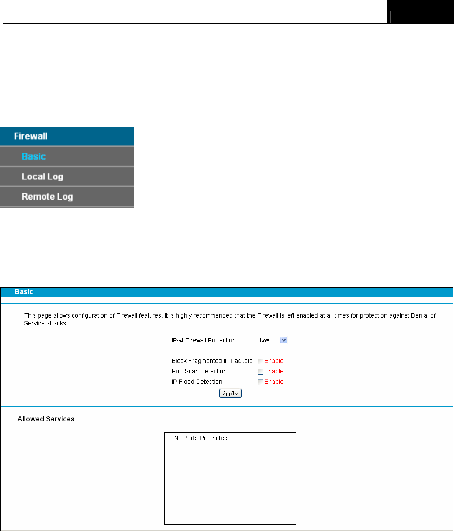
3.5 Firewall
Choose “Firewall”, there are several submenus under the main menu. Click any one of them, and
you will be able to configure the corresponding function.
3.5.1 Basic
Choose menu “Firewall” → “Basic”, and then you can configure the firewall features. It is highly
recommended that the Firewall is left enabled at all times for protection against Denial of Service
attacks.
Figure 3-20
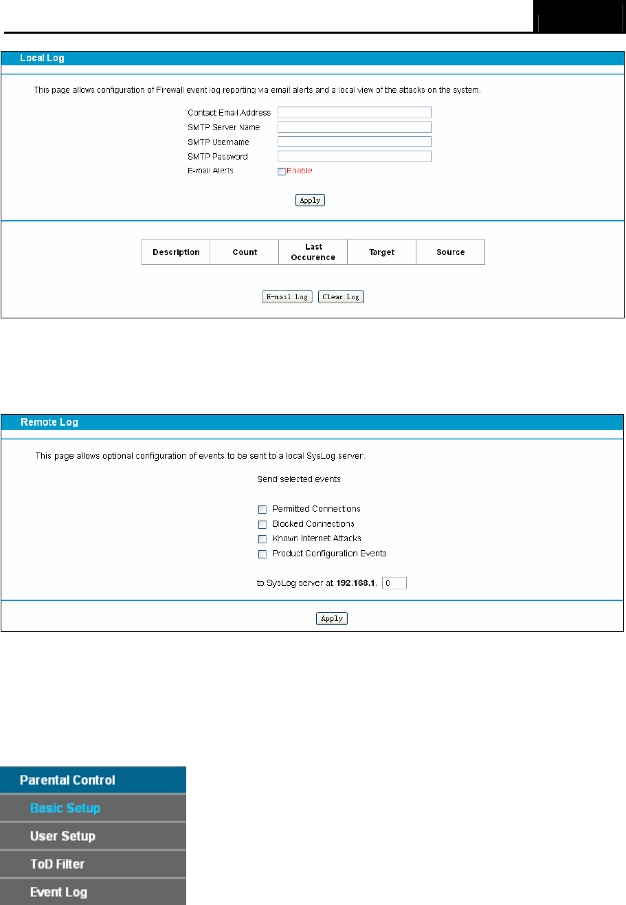
3.5.2 Local Log
This page allows configuration of Firewall event log reporting via email alerts and a local view of
the attacks on the system.
Archer CR700 User Guide
20
Figure 3-21
3.5.3 Remote Log
This page allows optional configuration of events to be sent to a local SysLog server.
Figure 3-22
3.6 Parental Control
Choose “Parental Control”, there are several submenus under the main menu. Click any one of
them, and you will be able to configure the corresponding function.
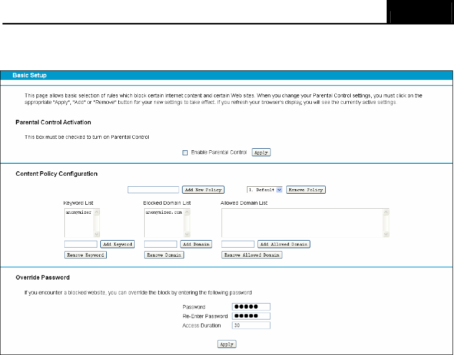
3.6.1 Basic Setup
This page allows basic selection of rules which block certain Internet content and certain Web
sites. When you change your Parental Control settings, you must click on the appropriate "Apply",
Archer CR700 User Guide
21
"Add" or "Remove" button for your new settings to take effect. If you refresh your browser's display,
you will see the currently active settings.
Figure 3-23
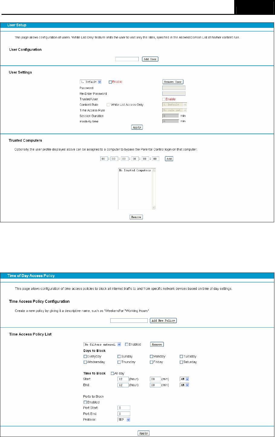
3.6.2 User Setup
This page allows configuration of users. 'White List Only' feature limits the user to visit only the
sites specified in the Allowed Domain List of his/her content rule.
Archer CR700 User Guide
22
Figure 3-24
3.6.3 ToD Filter
This page allows configuration of time access policies to block all internet traffic to and from
specific network devices based on time of day settings.
Archer CR700 User Guide
23
Figure 3-25
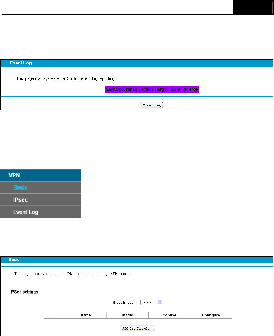
3.6.4 Event Log
This page displays Parental Control event log reporting.
Figure 3-26
3.7 VPN
Choose “VPN”, there are several submenus under the main menu. Click any one of them, and you
will be able to configure the corresponding function.
3.7.1 Basic
Choose “VPN”Æ“Basic”, you can Add/Remove or Enable/Disable the IPSec tunnel connections
on the screen as shown in Figure 3-27.
Figure 3-27
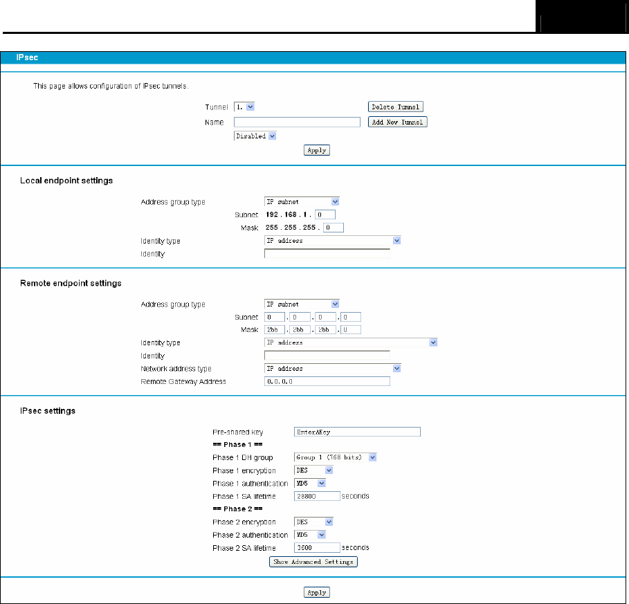
3.7.2 IPsec
Choose “VPN”Æ”IPsec”, and you can configure of an IPsec tunnel between two Archer CR700s.
Archer CR700 User Guide
24
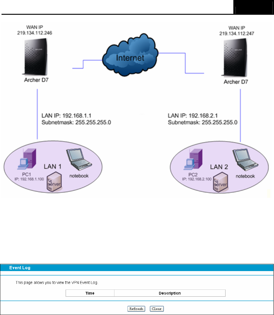
Figure 3-28
The topology is as follows.
Archer CR700 User Guide
25
) Note:
You could also use other VPN Routers to set VPN tunnels with Archer CR700. Archer CR700
supports up to 10 VPN tunnels simultaneously.
3.7.3 Event Log
This page allows you to view the VPN Event Log.
Figure 3-29
3.8 Wireless 2.4GHz
There are six submenus under the Wireless 2.4GHz menu. Click any of them, and you will be able
to configure the corresponding function.
Archer CR700 User Guide
26
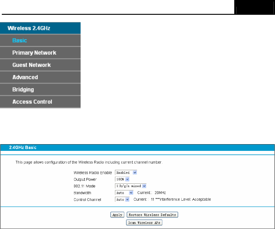
3.8.1 Basic
Choose menu “Wireless 2.4GHz” → “Basic”, you can configure the basic settings for the
wireless network of 2.4GHz on this page.
Figure 3-30
¾ 802.11 Mode: Select the desired mode. It is strongly recommended that you set the Mode to
802.11b/g/n mixed, and all of 802.11b, 802.11g, and 802.11n wireless stations can connect
to the modem router.
¾ Bandwidth: Select the channel width from the drop-down list. The default setting is Auto,
which can adjust the channel width for your clients automatically.
) Note:
If 11b/g mixed is selected in the 802.11 Mode field, the Bandwidth value will become 20M, which
is unable to be changed.
¾ Control Channel: Select the channel you want to use from the drop-down List of Channel.
This field determines which operating frequency will be used. It is not necessary to change the
wireless channel unless you notice interference problems with another nearby access point.
Click Save to save your settings.
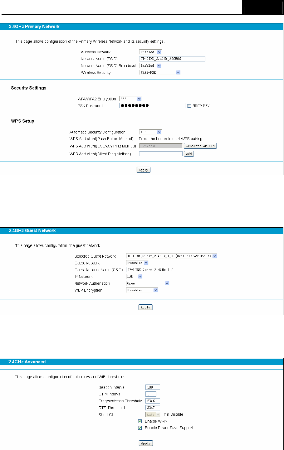
3.8.2 Primary Network
This page allows configuration of the Primary Wireless Network and its security settings.
Archer CR700 User Guide
27
Figure 3-31
3.8.3 Guest Network
This feature allows you to create a separate network for your guests without allowing them to
access your main network and the computers connected to it.
Figure 3-32
3.8.4 Advanced
This page allows configuration of data rates and WiFi thresholds.
Archer CR700 User Guide
28
Figure 3-33
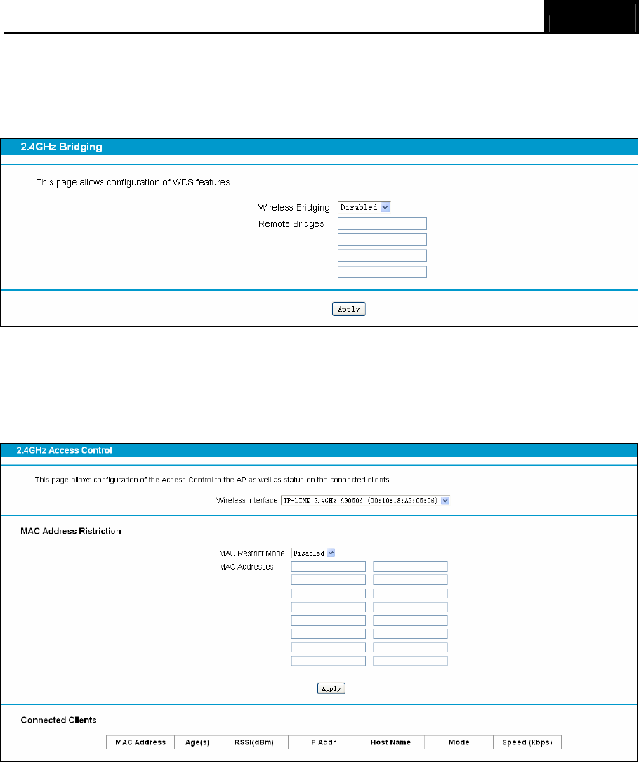
3.8.5 Bridging
This page allows configuration of WDS features.
Figure 3-34
3.8.6 Access Control
This page allows configuration of the Access Control to the AP as well as status on the connected
clients.
Figure 3-35
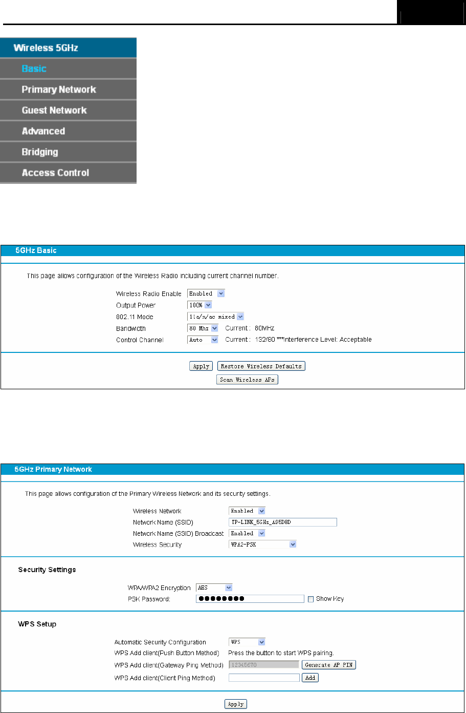
3.9 Wireless 5GHz
There are six submenus under the Wireless 5GHz menu. Click any of them, and you will be able to
configure the corresponding function.
Archer CR700 User Guide
29
3.9.1 Basic
Choose menu “Wireless5GHz” → “Basic”, you can configure the basic settings for the wireless
network of 5GHz on this page.
Figure 3-36
3.9.2 Primary Network
This page allows configuration of the Primary Wireless Network and its security settings.
Figure 3-37
Archer CR700 User Guide
30
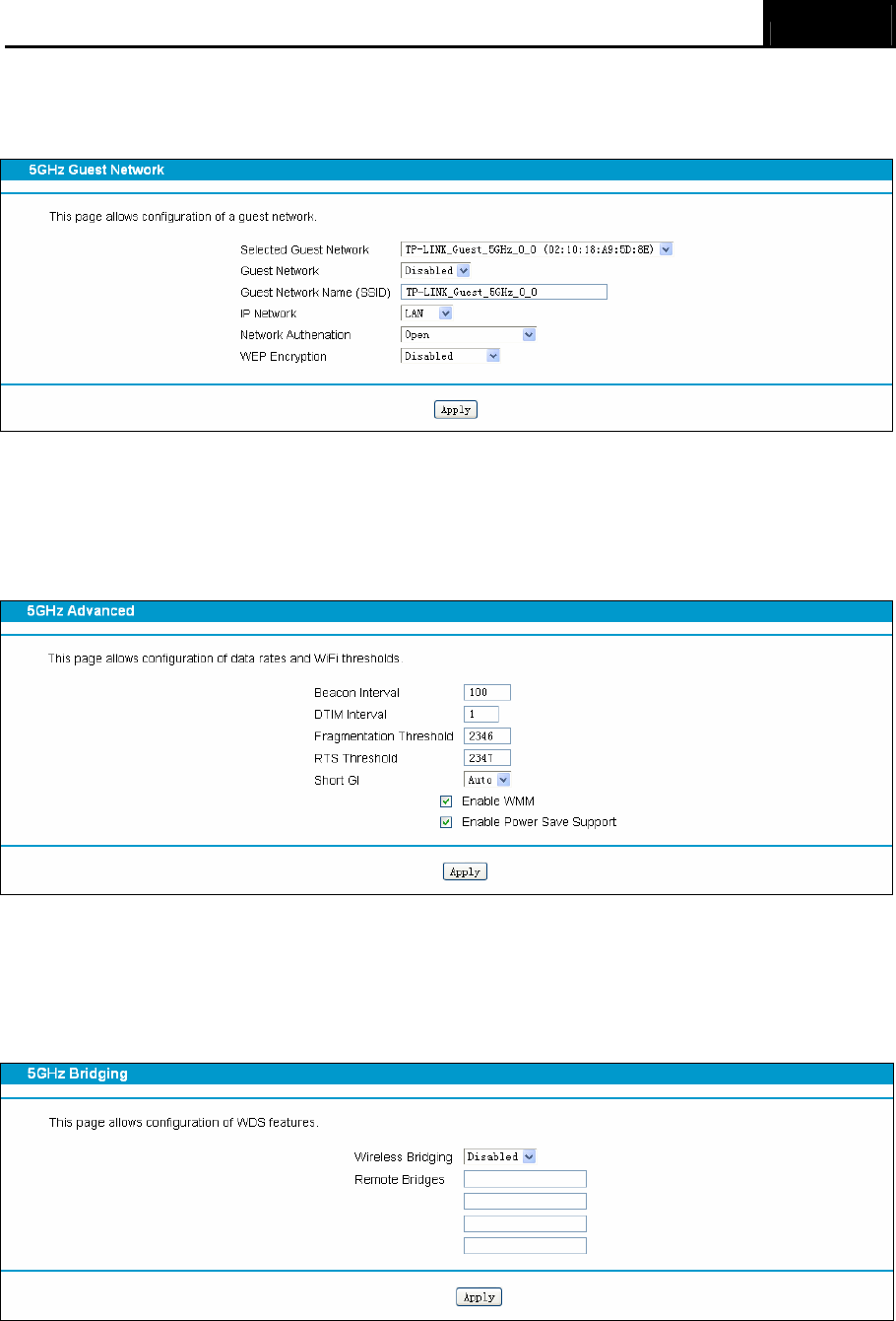
3.9.3 Guest Network
This page allows configuration of a guest network.
Figure 3-38
3.9.4 Advanced
This page allows configuration of data rates and WiFi thresholds.
Figure 3-39
3.9.5 Bridging
This page allows configuration of WDS features.
Figure 3-40
Archer CR700 User Guide
31
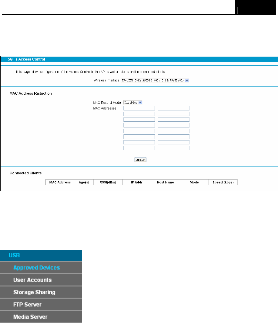
3.9.6 Access Control
This page allows configuration of the Access Control to the AP as well as status on the connected
clients
Figure 3-41
3.10 USB Settings
There are five submenus under the USB menu. Click any of them, and you will be able to
configure the corresponding function.
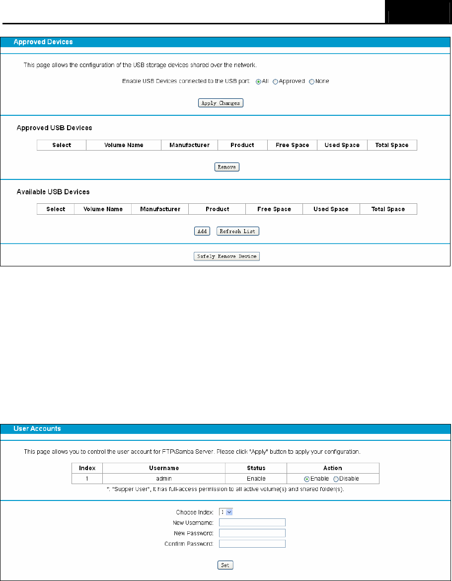
3.10.1 Approved Devices
Choose menu “USB” → ” Approved Devices”, you can configure a USB disk drive attached to
the modem router and view volume and share properties such as share name, capacity, status,
and action, etc on this page as shown below.
Archer CR700 User Guide
32
Figure 3-42
3.10.2 User Accounts
You can specify the user name and password for Storage Sharing and FTP Server users on this
page. Storage Sharing users can access the folders by entering the following URL into the
address field of your browser or Windows Explorer, such as. \\192.168.1.1. FTP Server users can
log into the FTP Server via FTP Client.
There are five users here, which provide means to control the access to the USB mass storage by
Storage Sharing or FTP. The Super User has the right to read and write to Storage Sharing and
FTP Server.
Figure 3-43
To add a new user account, please follow the steps below:
1. Choose the index from the drop-down list of Choose Index.
2. Self-define a New Username.
3. Enter the password in the New Password field.
4. Re-enter the password in the Confirm password field.
5. Click the Set button, and then a new entry will be added in the table.
Archer CR700 User Guide
33
To delete an existing user account, please click Delete in the Action column.
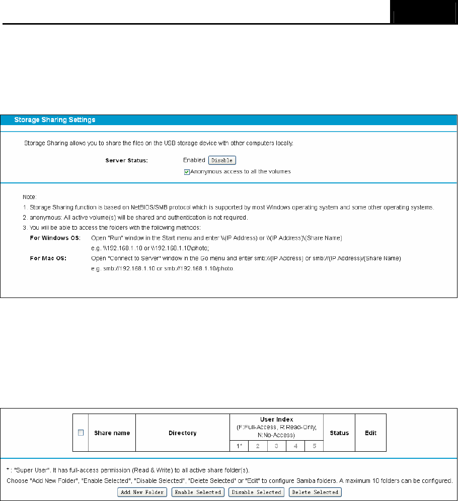
3.10.3 Storage Sharing
Choose menu “USB” → ”Storage Sharing”, you can configure a USB disk drive attached to the
modem router and view volume and share properties on this page as shown below.
Figure 3-44
¾ Server Status: Indicates the Storage Sharing's current status.
¾ Anonymous access to all the volumes: This function is enabled by default, so users can
access all activated volumes of Storage Sharing without accounts. If you want to add a
shared folder which does not allow anonymous login, uncheck the box to disable this
function. And Folder Table will be displayed as shown below.
¾ Share Name: This folder's display name.
¾ Directory: The real full path of the specified folder.
¾ User Access: The authorization of the user is displayed. * users mean Super Users who
have the full-access permission to all activated volumes and share folders. Grey users mean
the users who have no right to use this function. Others are common users.
¾ Status: The status of the entry is enabled or disabled.
¾ Edit: Click Edit in the table, and then you can modify the entry.
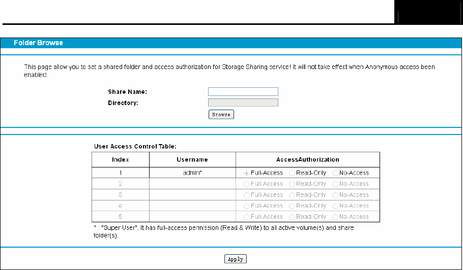
To add a new folder, follow the instructions below.
1. Click Add New Folder.
Archer CR700 User Guide
34
Figure 3-45
2. Click the Browse button, and then select the Select Volume from the drop-down list.
3. Enter display name of the share folder in Share Name filed.
4. Click the Apply button to apply the settings.
You can click the upper button to go to the upper folder
Click the Enable/Disable Selected button to enable or disable the selected entries.
Click the Delete Selected button to delete the selected entries.
) Note:
1. The max share folders number is 10. If you want to share a new folder when the number has
reached 10, you can delete an existing share folder and then add a new one.
2. If you want to change the Storage Sharing settings, you can click the Apply button to make
the changes take effect.
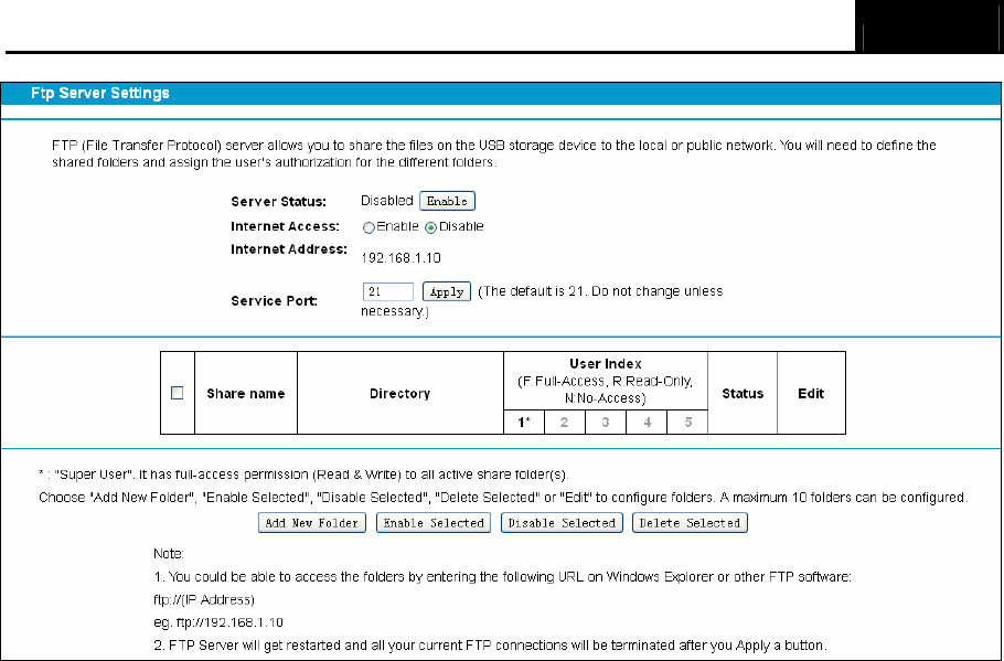
3.10.4 FTP Server
Choose menu “USB Settings”→”FTP Server”, you can create an FTP server that can be
accessed from the Internet or your local network.
Archer CR700 User Guide
35
Figure 3-46
¾ Server Status: Indicates the FTP Server's current status.
¾ Internet Access: If Internet Access is enabled, user(s) in public network can access FTP
server via Internet Address.
¾ Internet Address: If Internet Access is enabled, WAN IP will be displayed here.
¾ Service Port: Enter the FTP Port number to use. The default is 21.
¾ Share Name: This folder's display name.
¾ Directory: The real full path of the specified folder.
¾ User Index: The authorization of the user is displayed.
¾ Status: The status of the entry is enabled or disabled.
¾ Edit: Click Edit in the table, and then you can modify the entry.
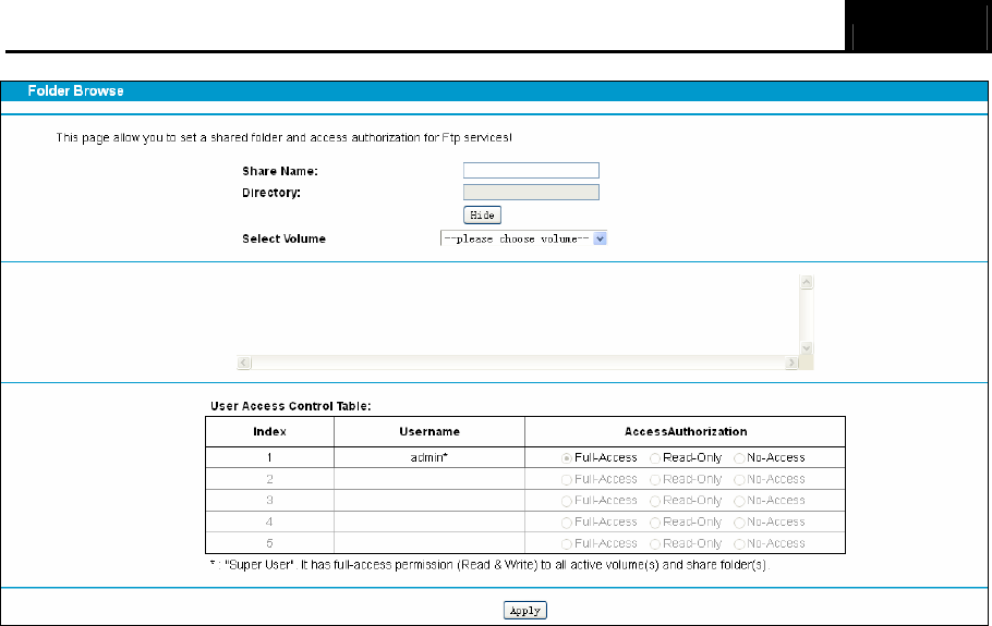
To add a new folder, follow the instructions below.
1. Click Add New Folder in Figure 3-46.
Archer CR700 User Guide
36
Figure 3-47
2. Click the Browse button, and then select the Select Volume from the drop-down list.
3. Enter display name of the share folder in Share Name filed.
4. Click the Apply button to apply the settings.
You can click the upper button to go to the upper folder.
Click the Enable/Disable Selected button to enable or disable the selected entries.
Click the Delete Selected button to delete the selected entries.
) Note:
1. The max share folders number is 10. If you want to share a new folder when the number has
reached 10, you can delete an existing share folder and then add a new one.
2. If you want to change the FTP settings, you can click the Apply button to make the changes
take effect.
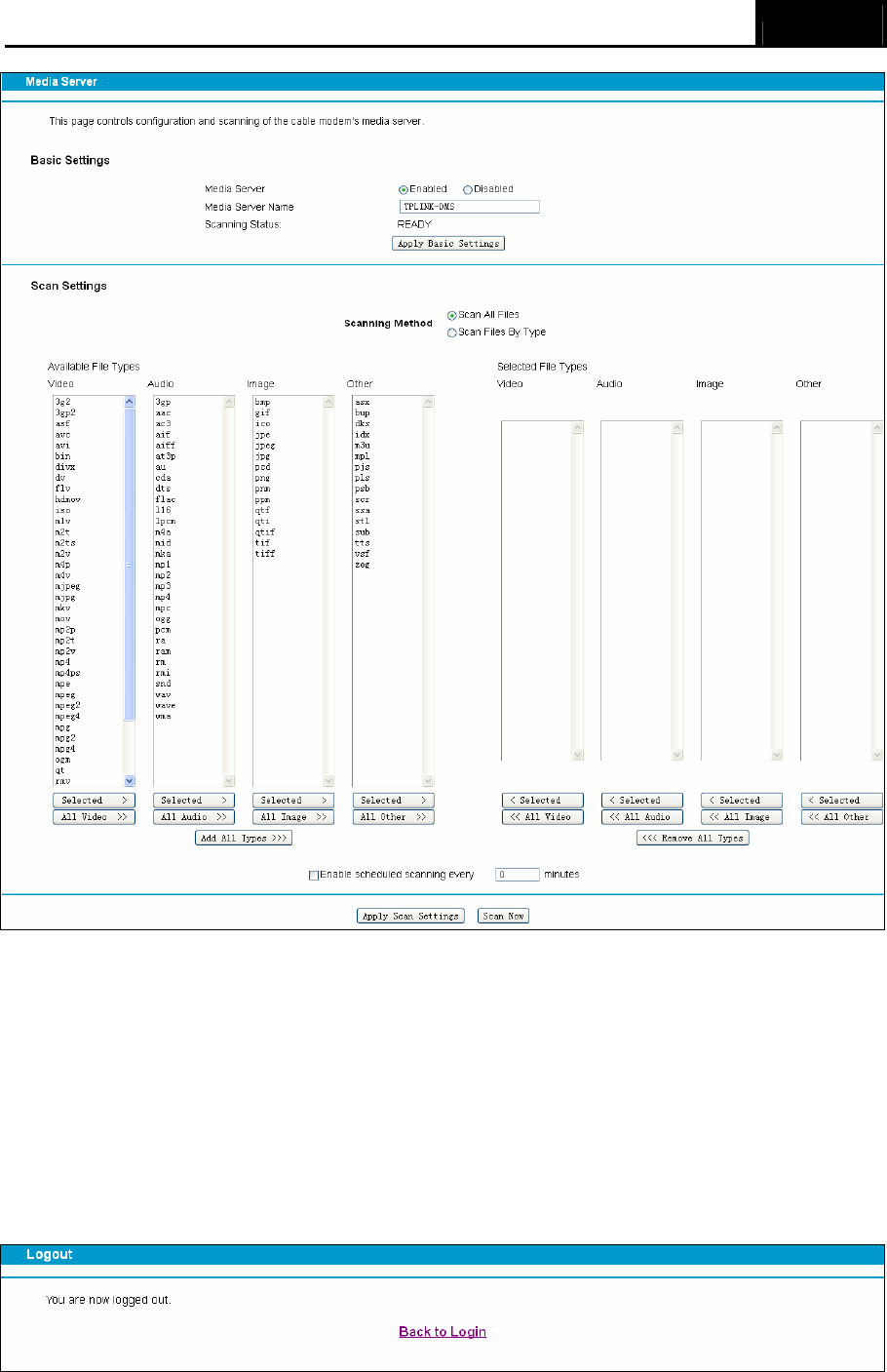
3.10.5 Media Server
Choose menu “USB”→”Media Server”, you can create media server that allows you to share
stored content with other computers and devices on your home network and on the Internet.
Archer CR700 User Guide
37
Figure 3-48
) Note:
The max share folders number is 6. If you want share a new folder when the numbers has been
reached to be 6, you can delete a share folder and then add a new one.
3.11 Logout
Choose “Logout”, and you see the screen as shown in Figure 3-49. Click Back to Login and you
will be redirect to the login screen.
Figure 3-49

Archer CR700 User Guide
38
Appendix A: Specifications
HARDWARE FEATURES
IEEE Standards IEEE 802.3, 802.3u
Certification CE, FCC, RoHS, CableLabs
DOCSIS Standards
DOCSIS 3.0/EuroDOCSIS 3.0
DOCSIS 2.0/EuroDOCSIS 2.0
DOCSIS 1.1/EuroDOCSIS 1.1
DOCSIS 1.0/EuroDOCSIS 1.0
Interface
1 F-Connector, female 75 Ω
4 10/100/1000Mbps RJ45 LAN Ports
2 USB 2.0 Ports
Button
1 Power On/Off¬ Button
1 Wi-Fi On/Off¬ Button
1 WPS Button
1 Reset Button
External Power Supply 12VDC/3.5A
Antenna Type Omni directional, Internal
Antenna Gain 3×5dBi for 2.4GHz and 5GHz
Maximum PHY Rate DOCSIS Up to 680 Mbps
EuroDOCSIS Up to 880 Mbps
Bandwidth
DOCSIS 96 MHz(16 channels) / 6MHz
(single channel)
EuroDOCSIS 128 MHz(16 channels) / 6MHz
(single channel)
WIRELESS FEATURES
Wireless Standards IEEE 802.11ac/n/a 5GHz
IEEE 802.11b/g/n 2.4GHz
Wireless Speeds 5GHz: Up to 1300Mbps
2.4GHz: Up to 450Mbps
Frequency 2.4GHz and 5GHz
Wireless Security 64/128-bit WEP,WPA/WPA2,WPA-PSK/
WPA2-PSK encryption, Wireless MAC Filtering
Physical and Environment
Working Temperature 0 ~ 40℃℃
Working Humidity 10% ~ 90% RH (non-condensing)

Archer CR700 User Guide
39
Storage Temperature -40 ~ 70℃℃
Storage Humidity 5% ~ 90% RH (non-condensing)

Archer CR700 User Guide
40
Appendix B: Technical Support
Technical Support
For more troubleshooting help, go to:
http://www.tp-link.com/en/support/faq
To download the latest Firmware, Driver, Utility and User Guide, go to:
http://www.tp-link.com/en/support/download
For all other technical support, please contact us by using the following details:
Global
Tel: +86 755 2650 4400
Fee: Depending on rate of different carriers, IDD.
E-mail: support@tp-link.com
Service time: 24hrs, 7 days a week
USA/Canada
Toll Free: +1 866 225 8139
E-mail: support.usa@tp-link.com (USA)
support.ca@tp-link.com (Canada)
Service time: 24hrs, 7 days a week
Turkey
Tel: 0850 7244 488 (Turkish Service)
Fee: Depending on rate of different carriers.
E-mail: support.tr@tp-link.com
Service time: 09:00 to 21:00, 7 days a week
Ukraine
Tel: 0800 505 508
Fee: Free for Landline; Mobile: Depending on rate
of different carriers
E-mail: support.ua@tp-link.com
Service time: Monday to Friday, 10:00 to 22:00
Brazil
Toll Free: 0800 608 9799 (Portuguese Service)
E-mail: suporte.br@tp-link.com
Service time: Monday to Friday, 09:00 to 20:00;
Saturday, 09:00 to 15:00
Indonesia
Tel: (+62) 021 6386 1936
Fee: Depending on rate of different carriers.
E-mail: support.id@tp-link.com
Service time: Monday to Friday, 09:00 to 12:00,
13:00 to 18:00 *Except public holidays
Australia/New Zealand
Tel: NZ 0800 87 5465 (Toll Free)
AU 1300 87 5465 (Depending on 1300 policy.)
E-mail: support.au@tp-link.com (Australia)
support.nz@tp-link.com (New Zealand)
Service time: 24hrs, 7 days a week
Germany/Austria
Tel: +49 1805 875 465 (German Service)
+49 1805 TPLINK
+43 820 820 360
Fee: Landline from Germany: 0.14EUR/min.
Landline from Austria: 0.20EUR/min.
E-mail: support.de@tp-link.com
Service time: Monday to Friday, 09:00 to 12:30
and 13:30 to 18:00. GMT+1 or GMT+2 (DST in
Germany) *Except bank holidays in Hesse
Singapore
Tel: +65 6284 0493
Fee: Depending on rate of different carriers.
E-mail: support.sg@tp-link.com
Service time: 24hrs, 7 days a week
UK
Tel: +44 (0) 845 147 0017
Fee: Landline: 1p-10.5p/min, depending on the time
of day. Mobile: 15p-40p/min, depending on your
mobile network.
E-mail: support.uk@tp-link.com
Service time: 24hrs, 7 days a week
Italy
Tel: +39 023 051 9020
Fee: Depending on rate of different carriers.
E-mail: support.it@tp-link.com
Service time: Monday to Friday, 09:00 to 13:00;
14:00 to 18:00
Malaysia
Toll Free: 1300 88 875 465
Email: support.my@tp-link.com
Service time: 24hrs, 7 days a week
Poland
Tel: +48 (0) 801 080 618
+48 223 606 363 (if calls from mobile phone)
Fee: Depending on rate of different carriers.
E-mail: support.pl@tp-link.com
Service time: Monday to Friday, 09:00 to 17:00.
GMT+1 or GMT+2 (DST)
France
Tel: 0820 800 860 (French service)
Fee: 0.118 EUR/min from France
Email: support.fr@tp-link.com
Service time: Monday to Friday, 09:00 to 18:00
*Except French Bank holidays
Switzerland
Tel: +41 (0) 848 800 998 (German Service)
Fee: 4-8 Rp/min, depending on rate of different
time.
E-mail: support.ch@tp-link.com
Service time: Monday to Friday, 09:00 to 12:30 and
13:30 to 18:00. GMT+1 or GMT+2 (DST)
Russian Federation
Tel: 8 (499) 754 5560 (Moscow NO.)
8 (800) 250 5560 (Toll-free within RF)
E-mail: support.ru@tp-link.com
Service time: From 09:00 to 21:00 (Moscow time)
*Except weekends and holidays in RF