TP Link Technologies MR3020 Portable 3G/3.75G Wireless N Router User Manual User s manual FCC
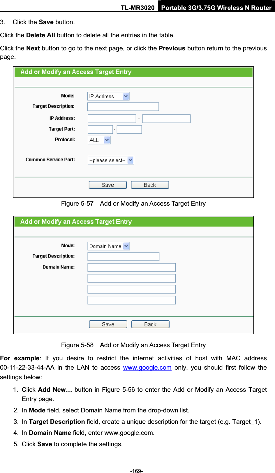
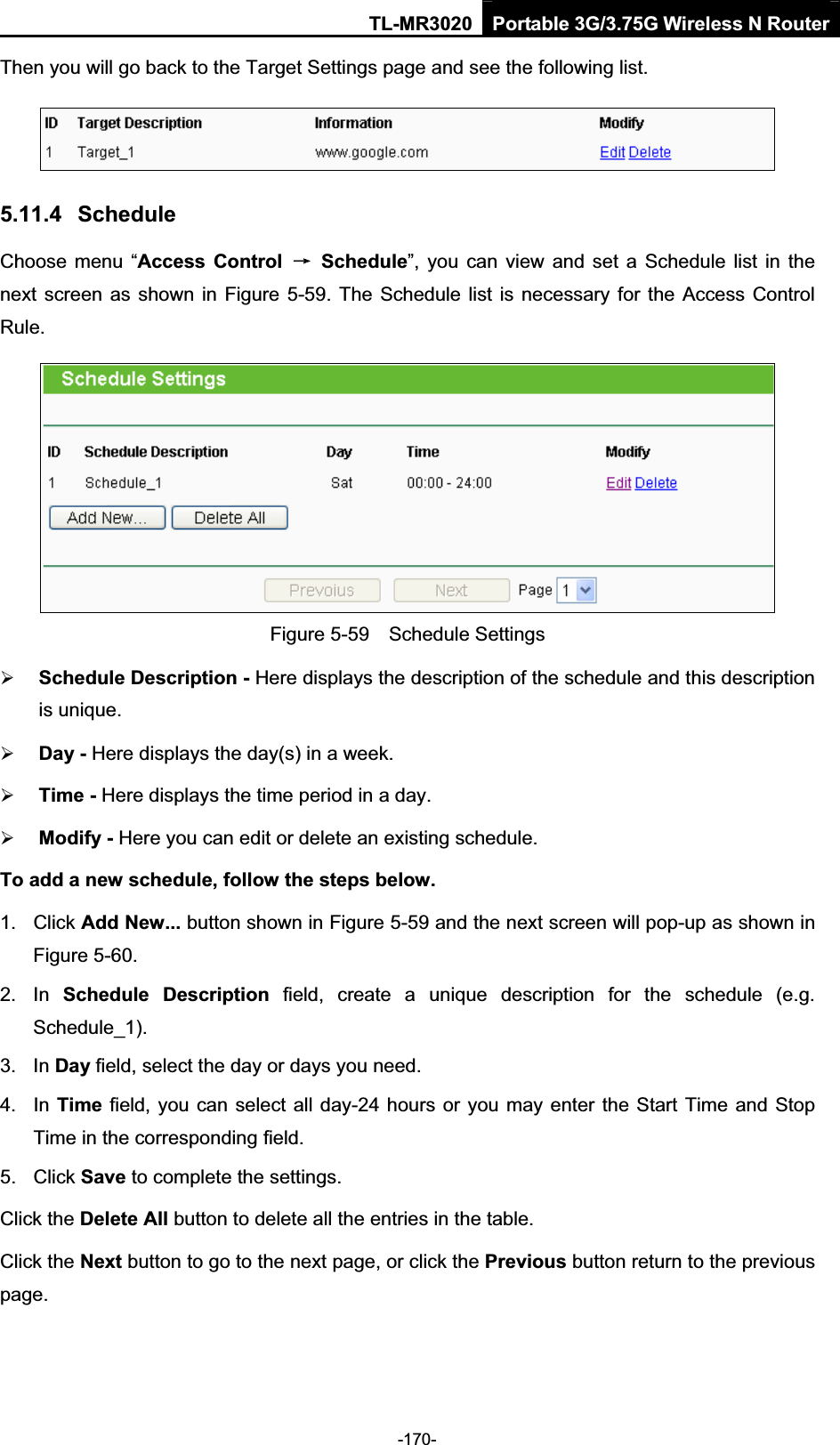
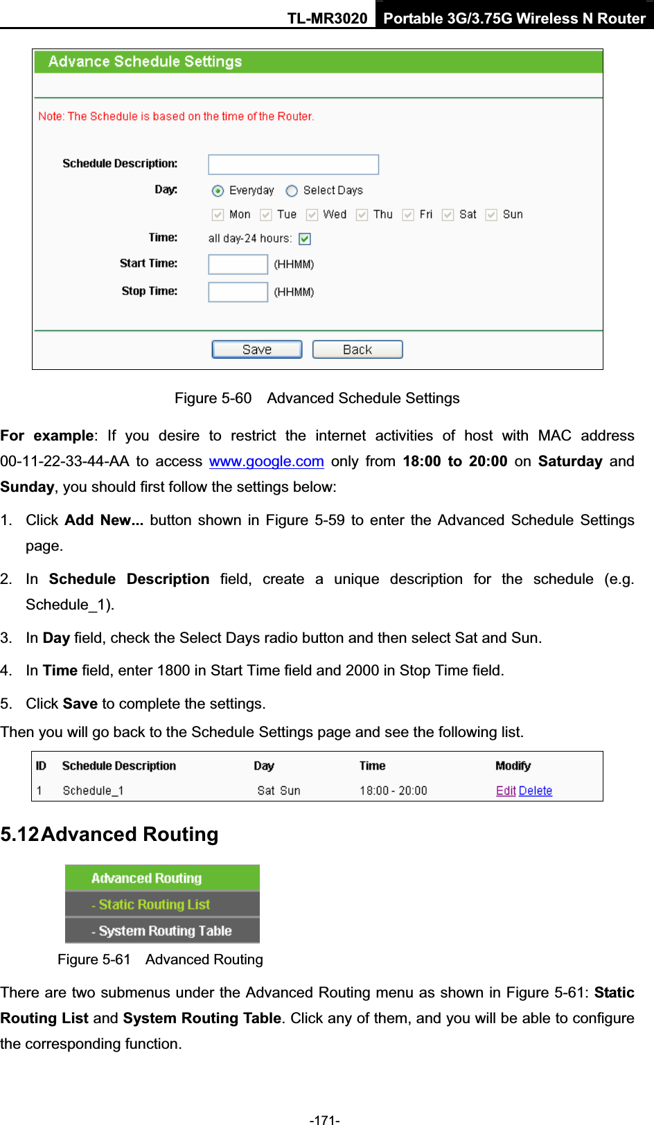
TP-Link Technologies Co., Ltd. Portable 3G/3.75G Wireless N Router User s manual FCC
UserManual.wiki
>
TP Link Technologies
>
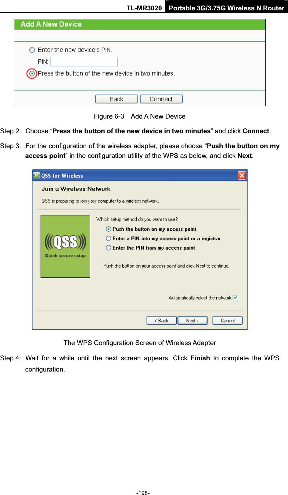
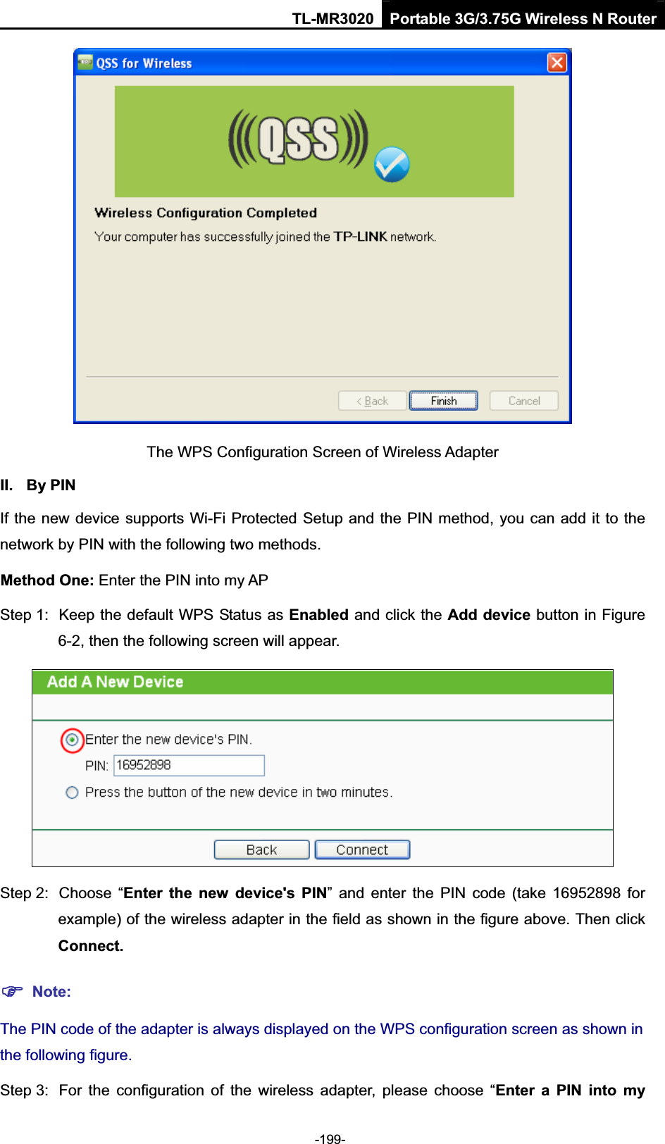
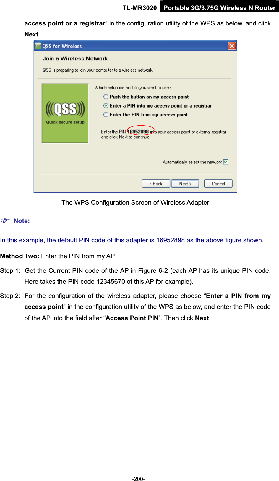
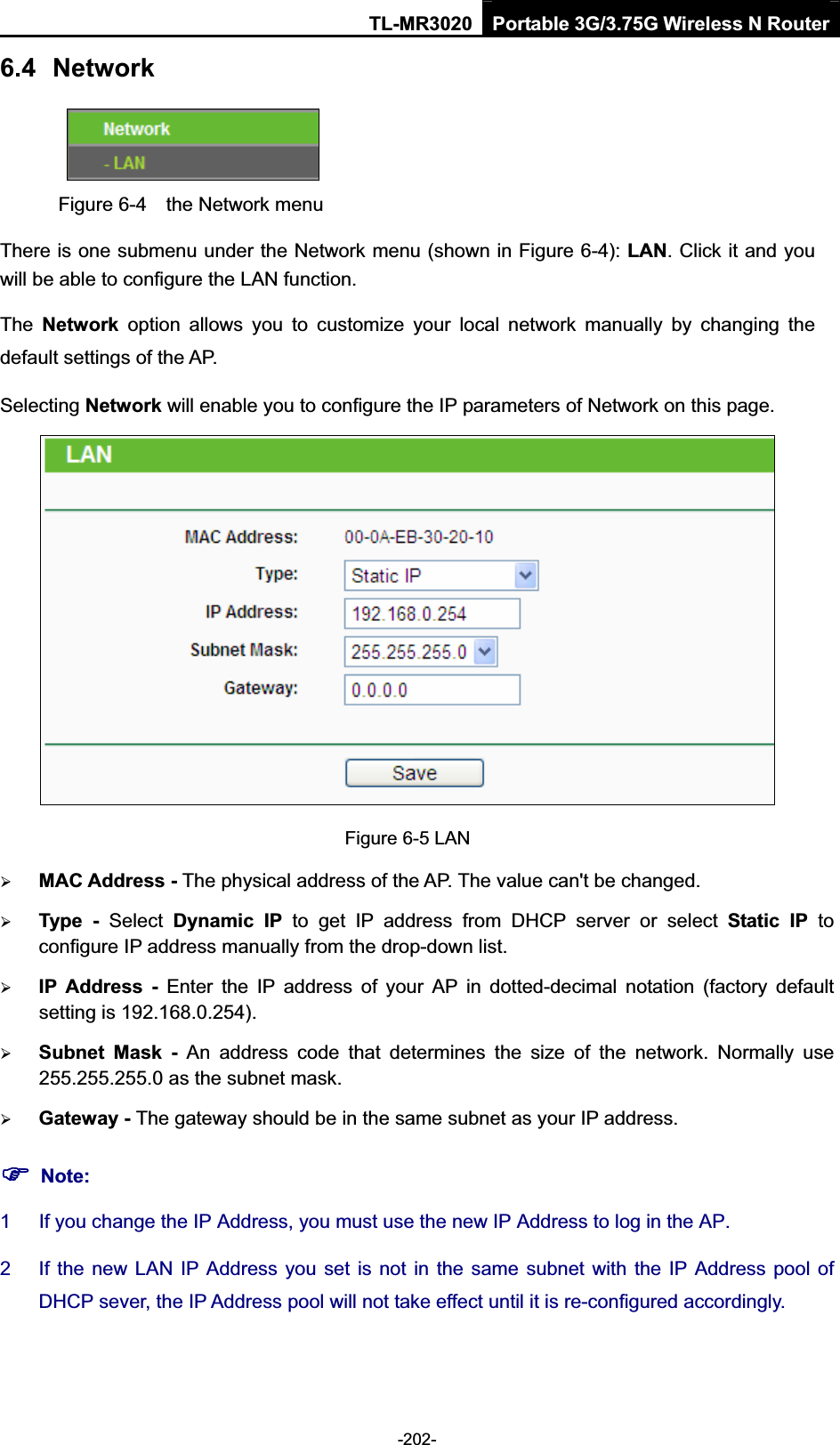
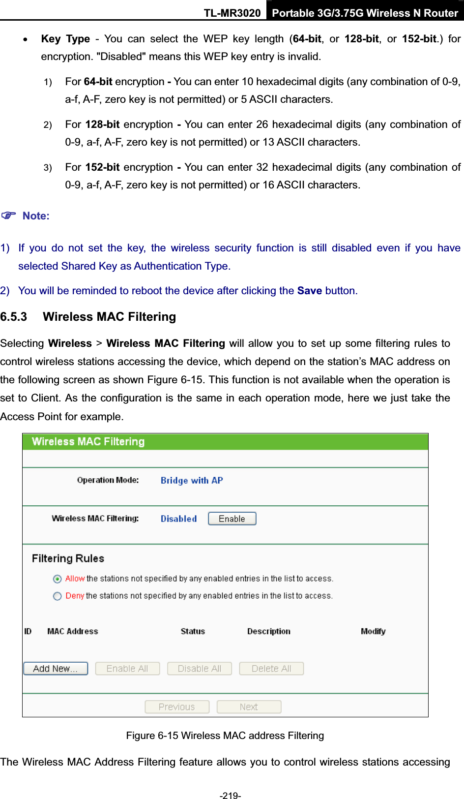
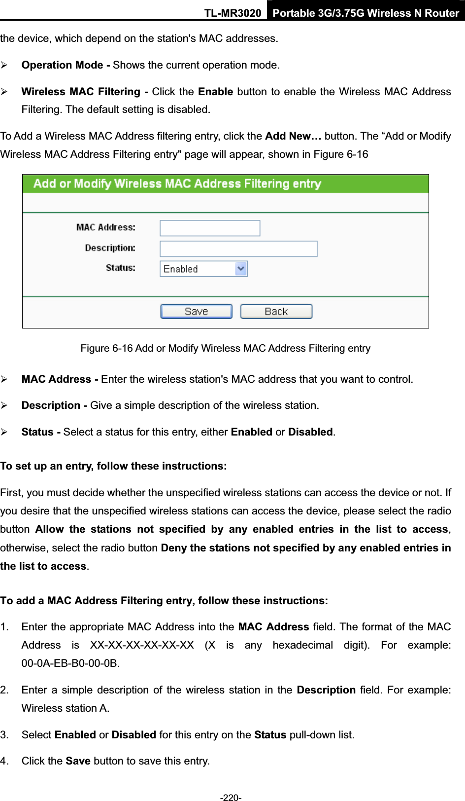
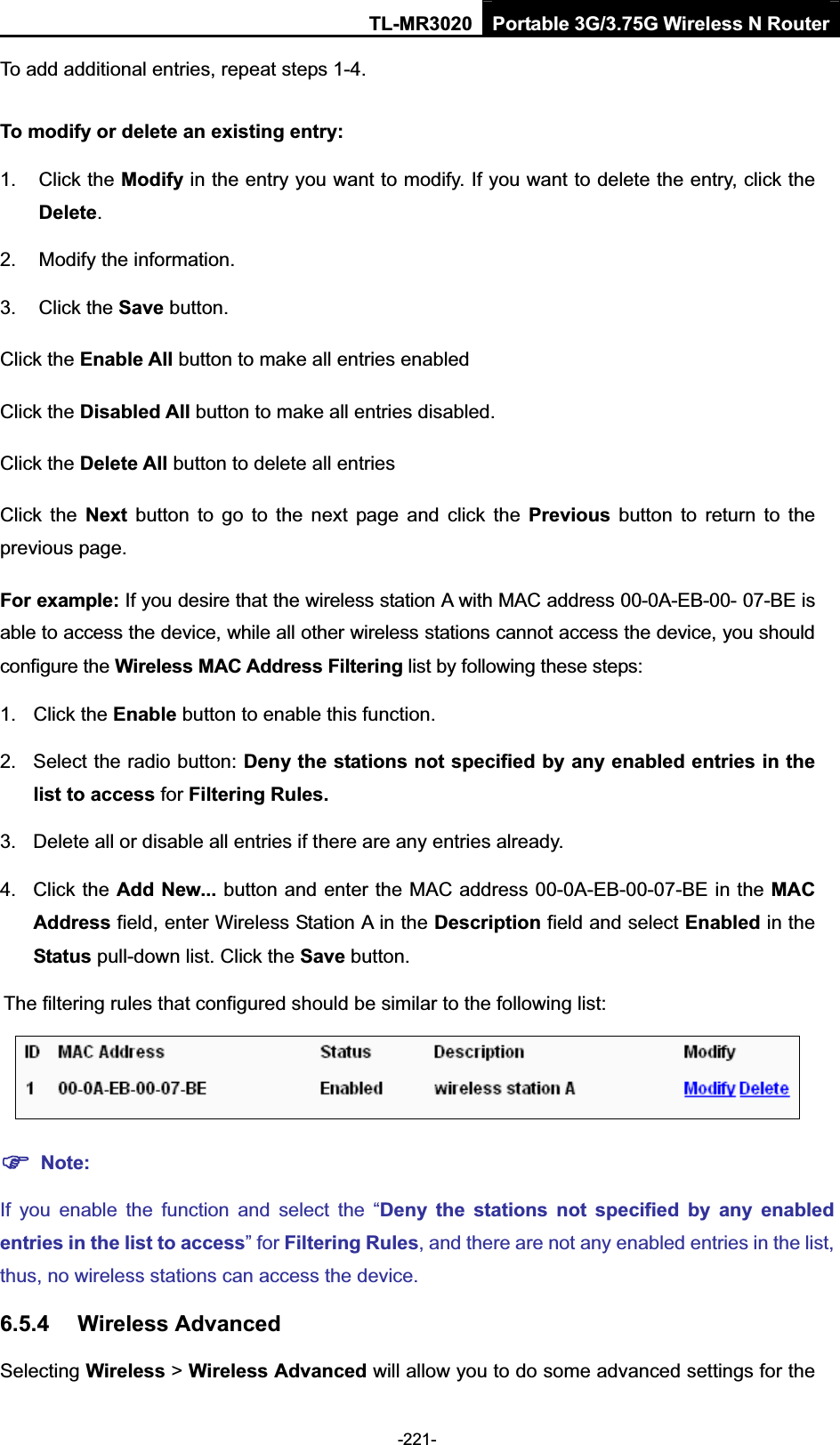
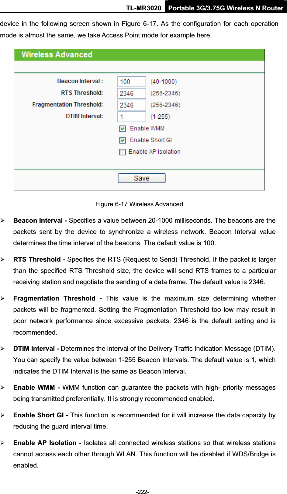
MR3020 User Manual
User Manual
Navigation menu
Upload a User Manual
Namespaces
Wiki Guide
HTML
PDF
Info
Views
User Manual
Discussion / Help
Navigation
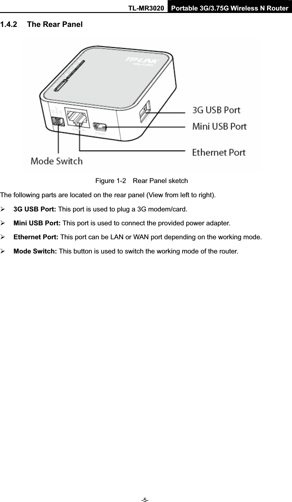
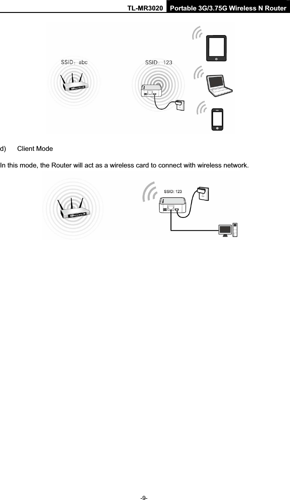
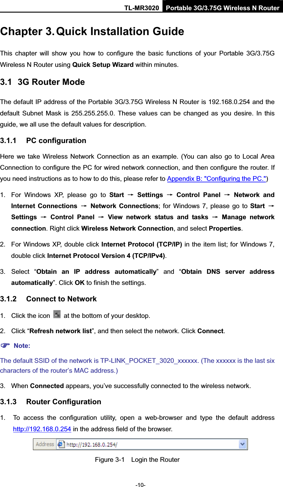
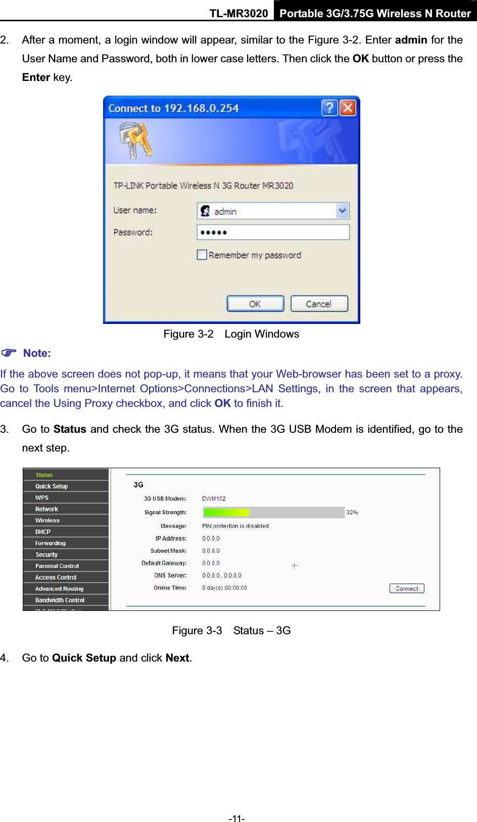
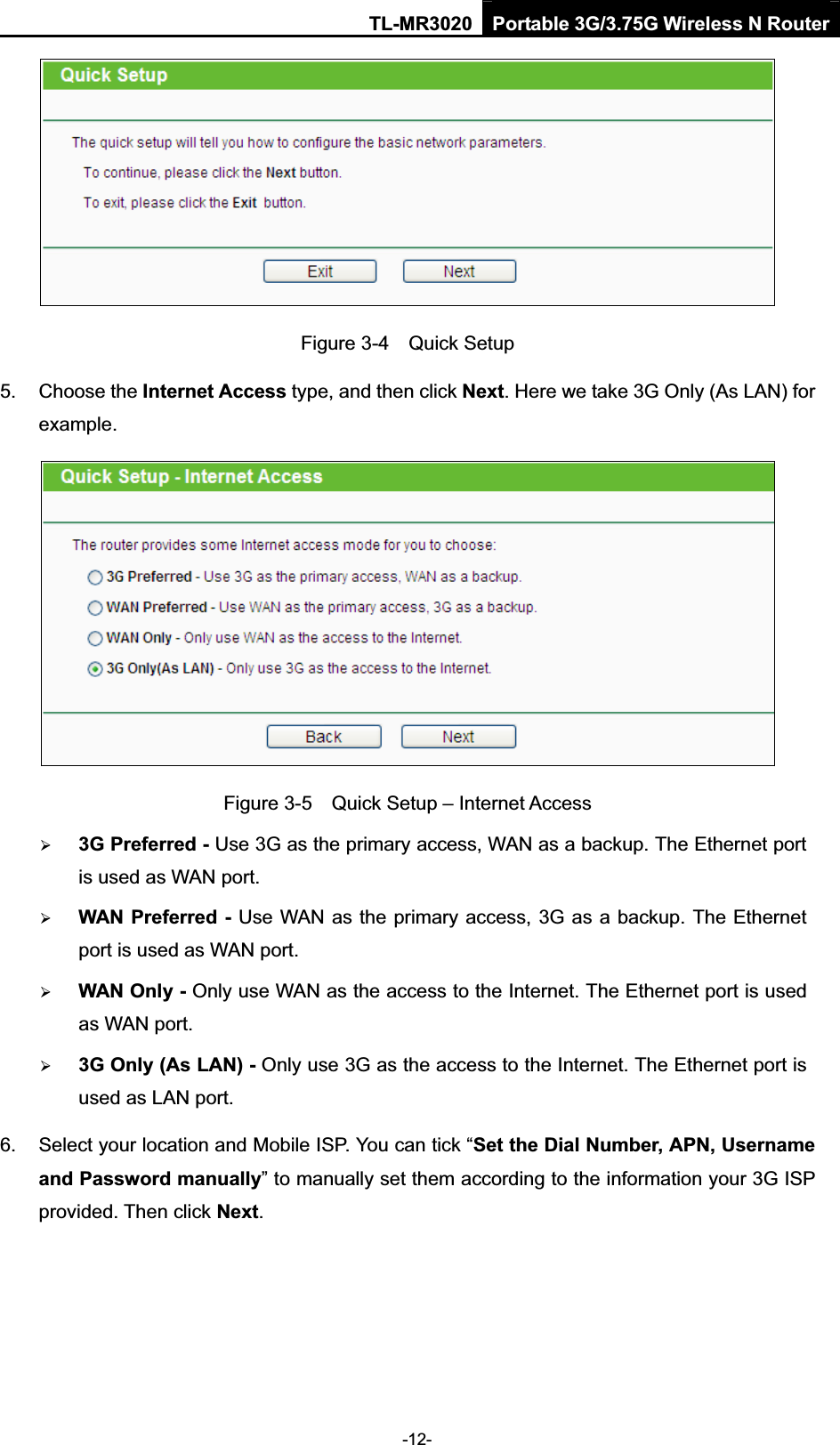
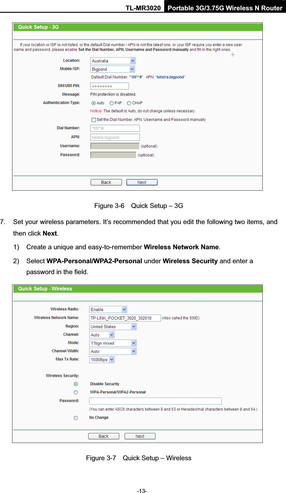
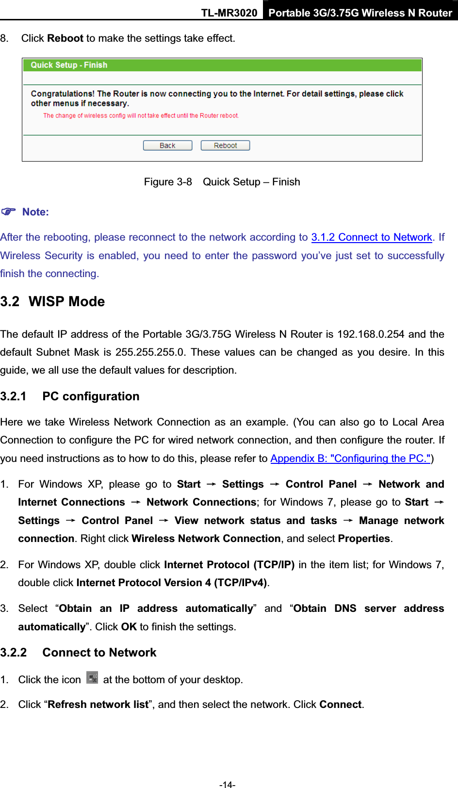
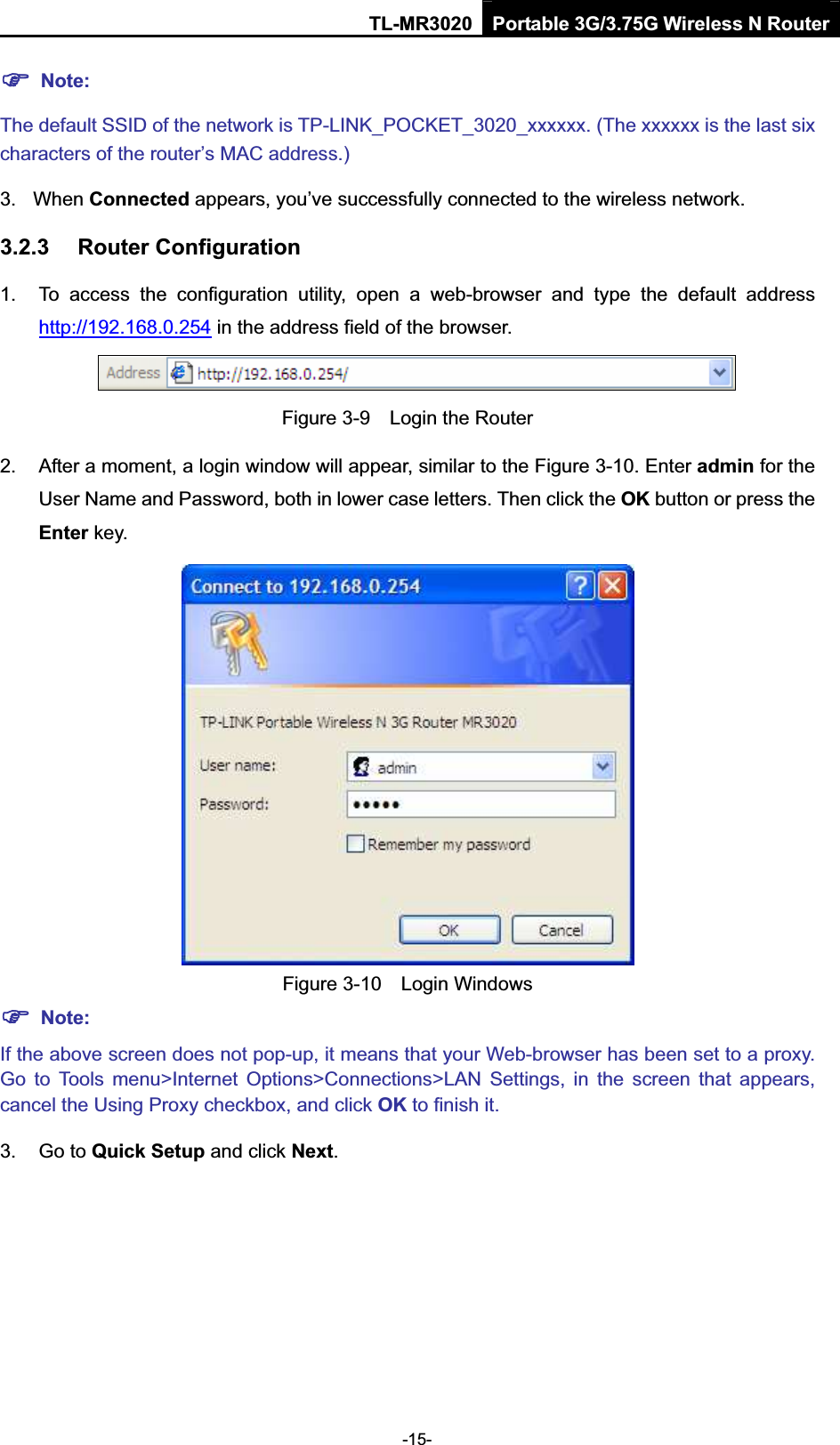
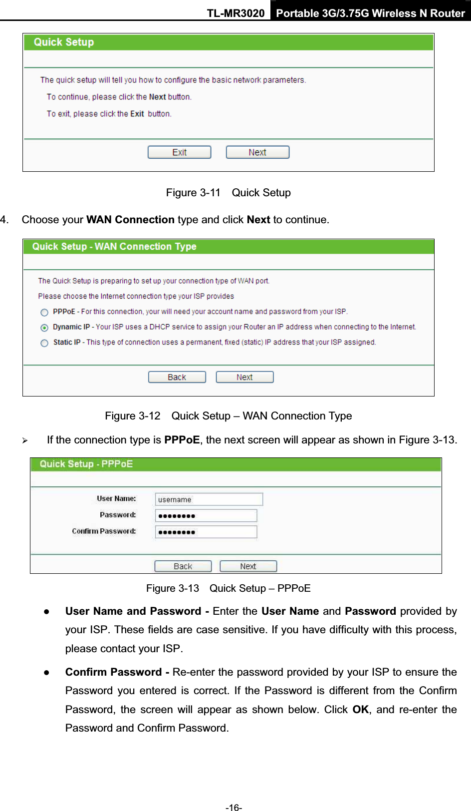

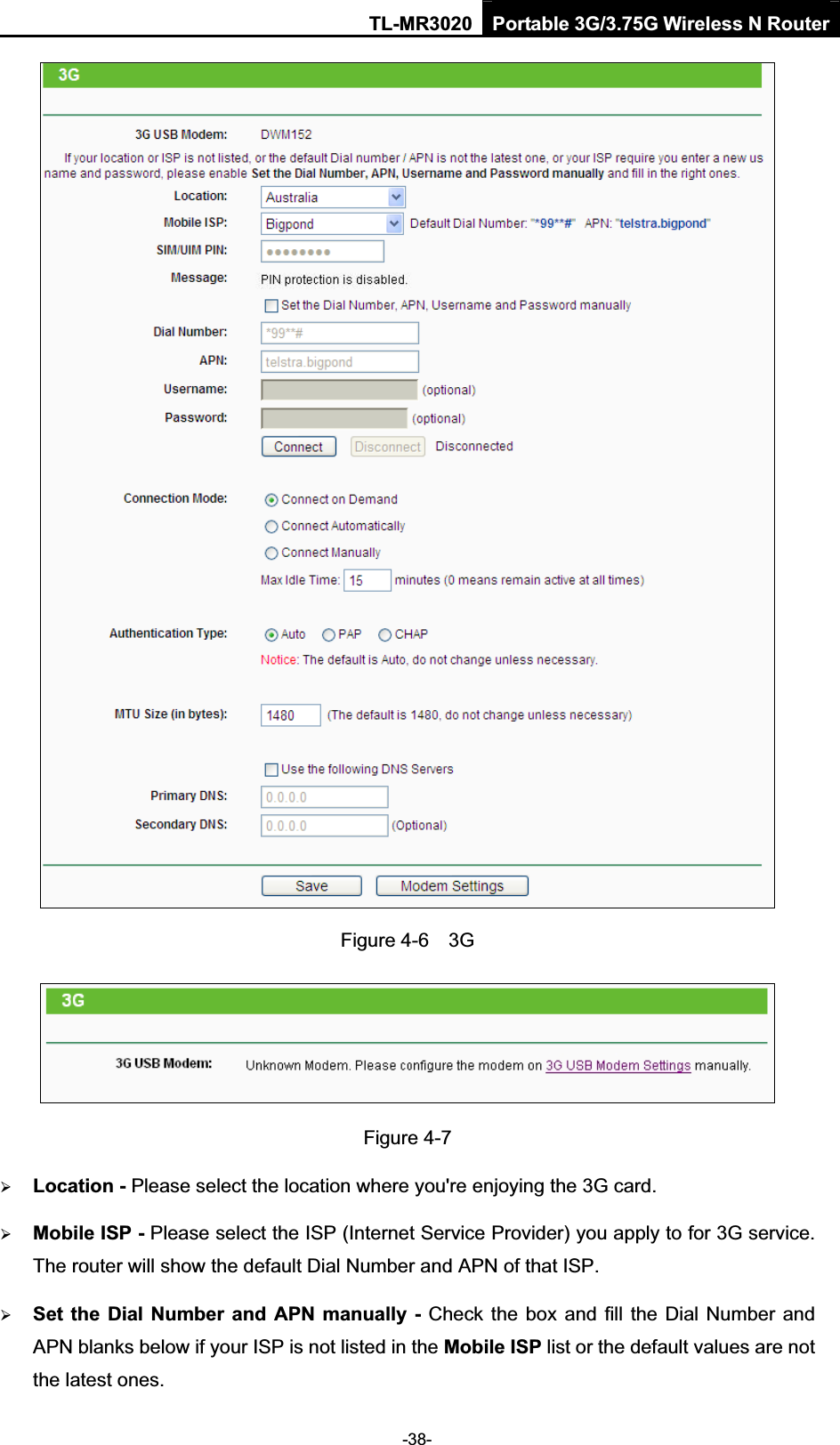
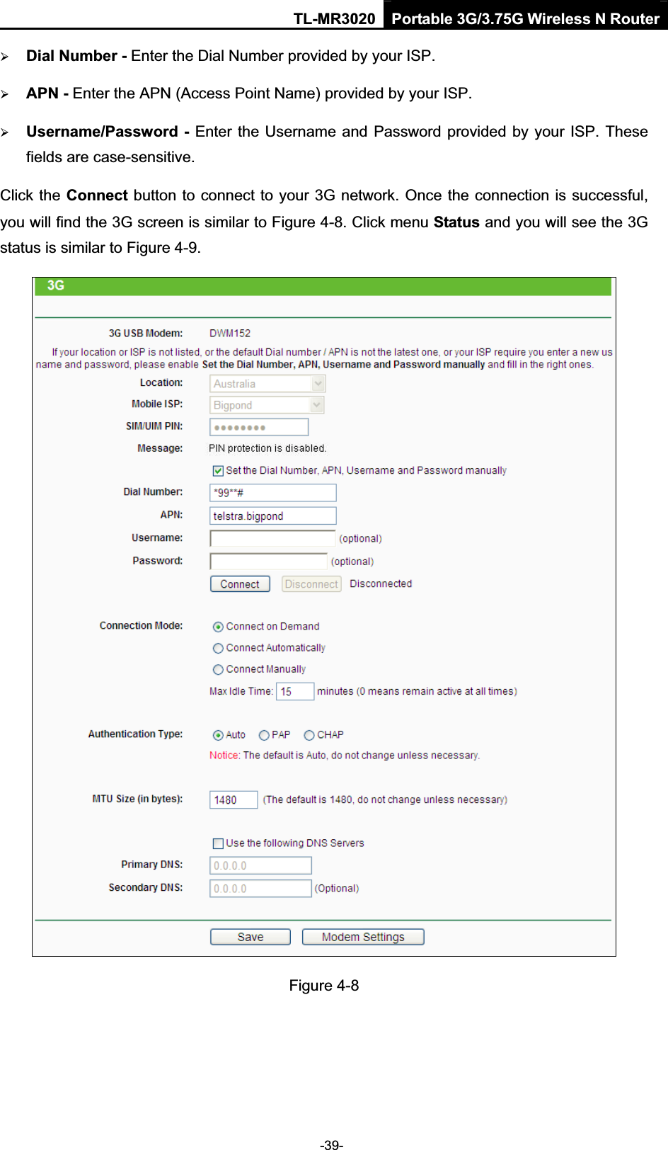
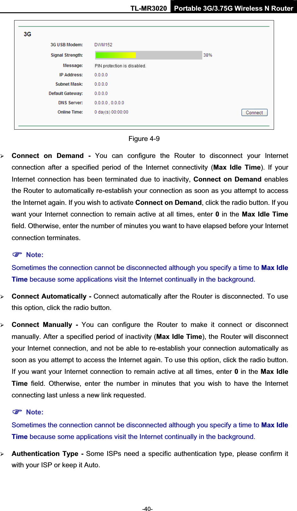
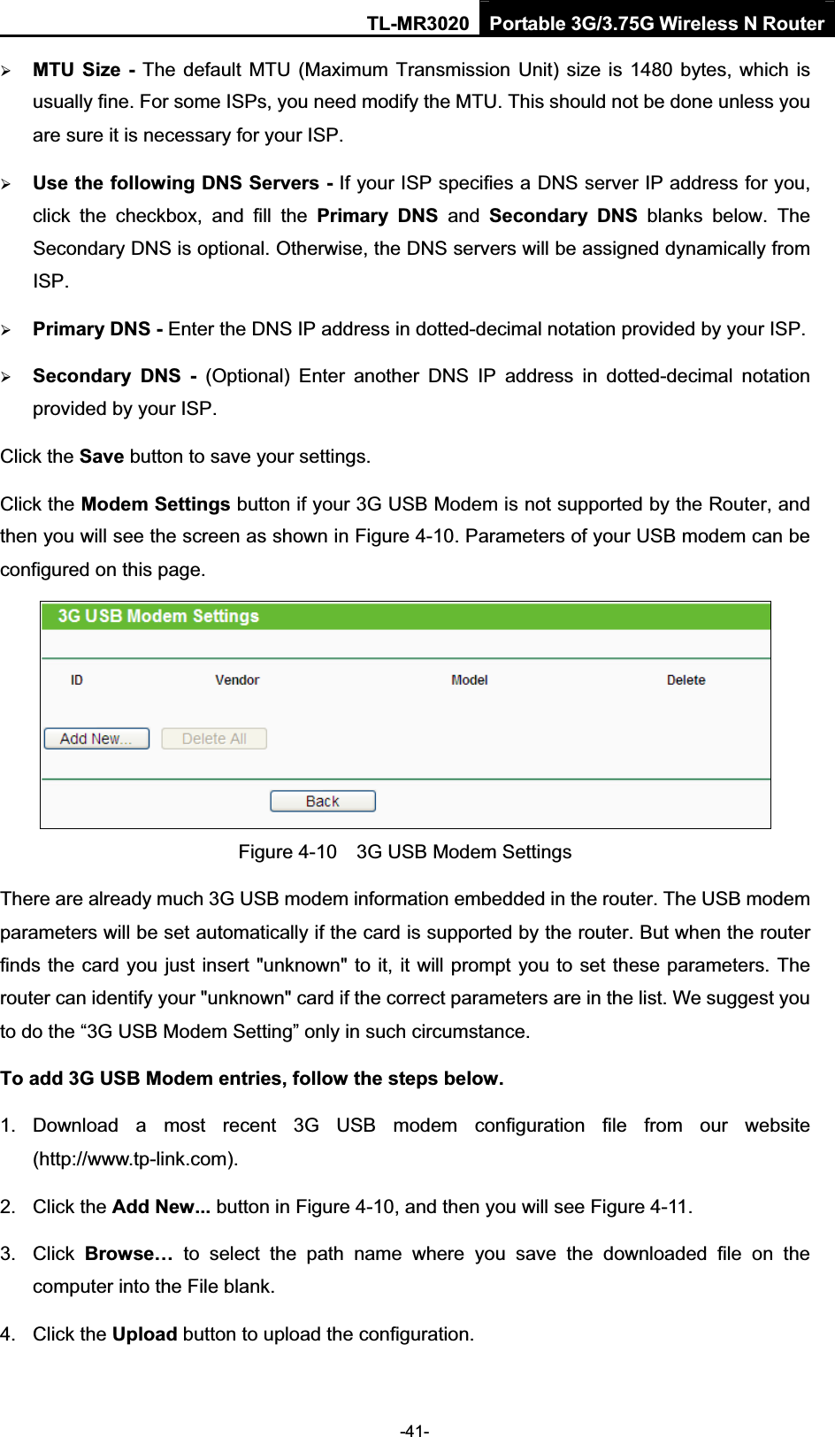
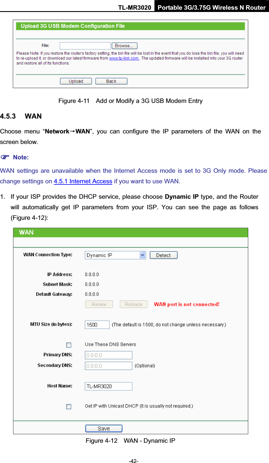
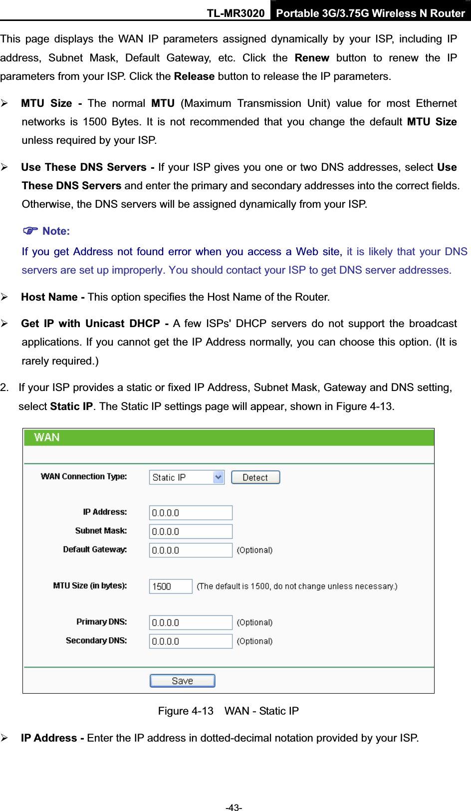
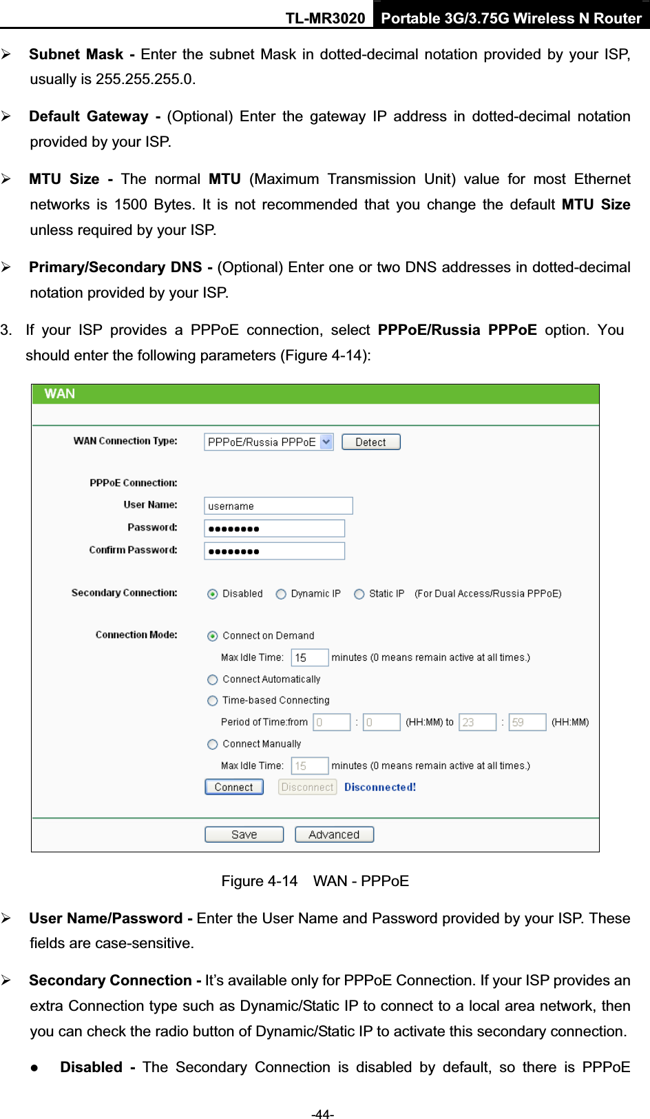
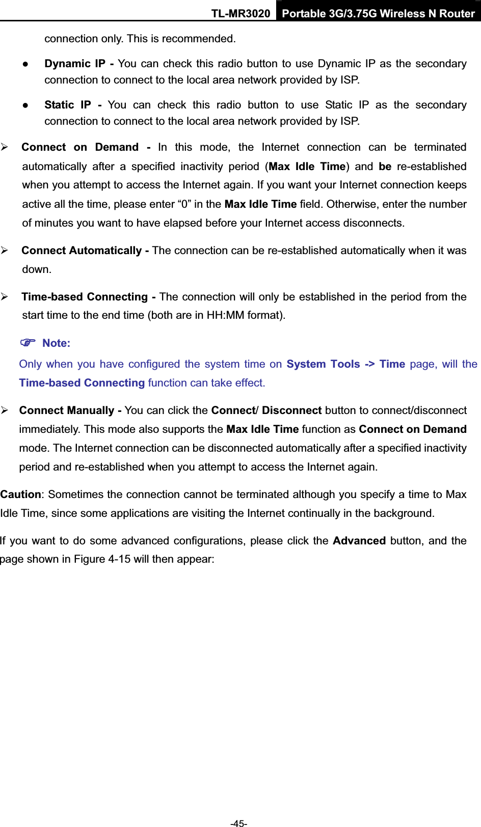
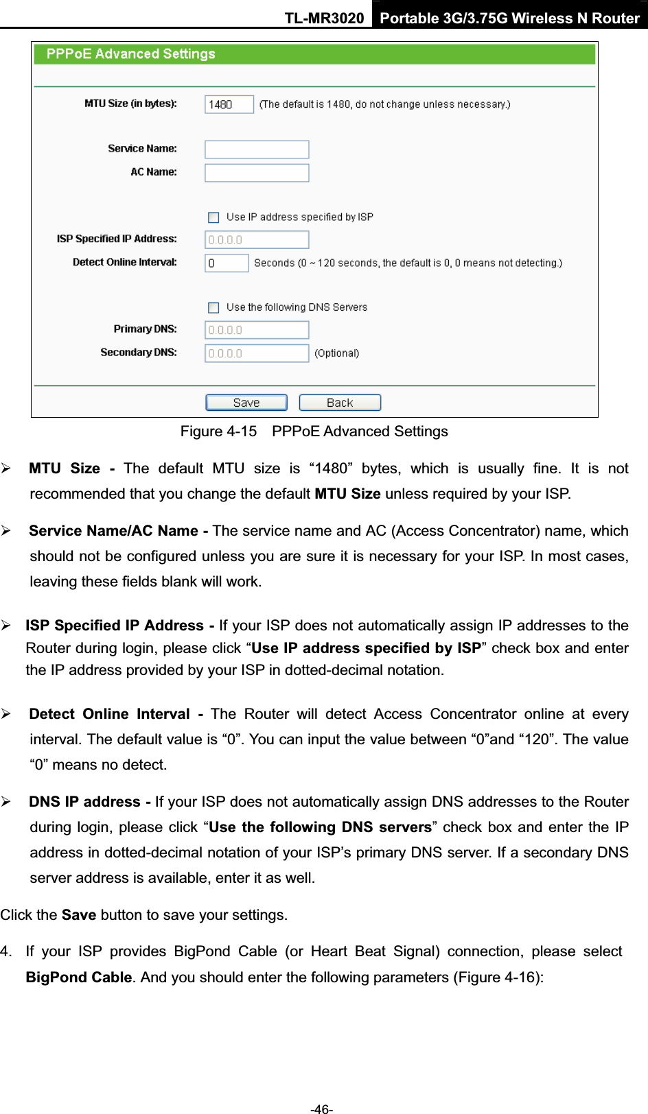
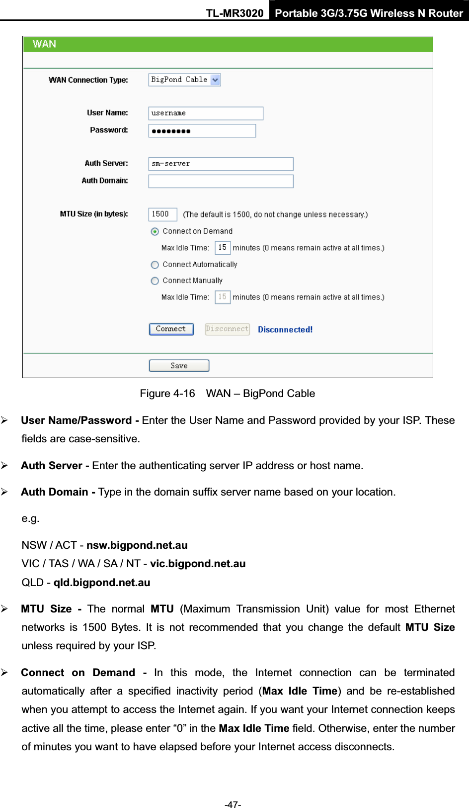

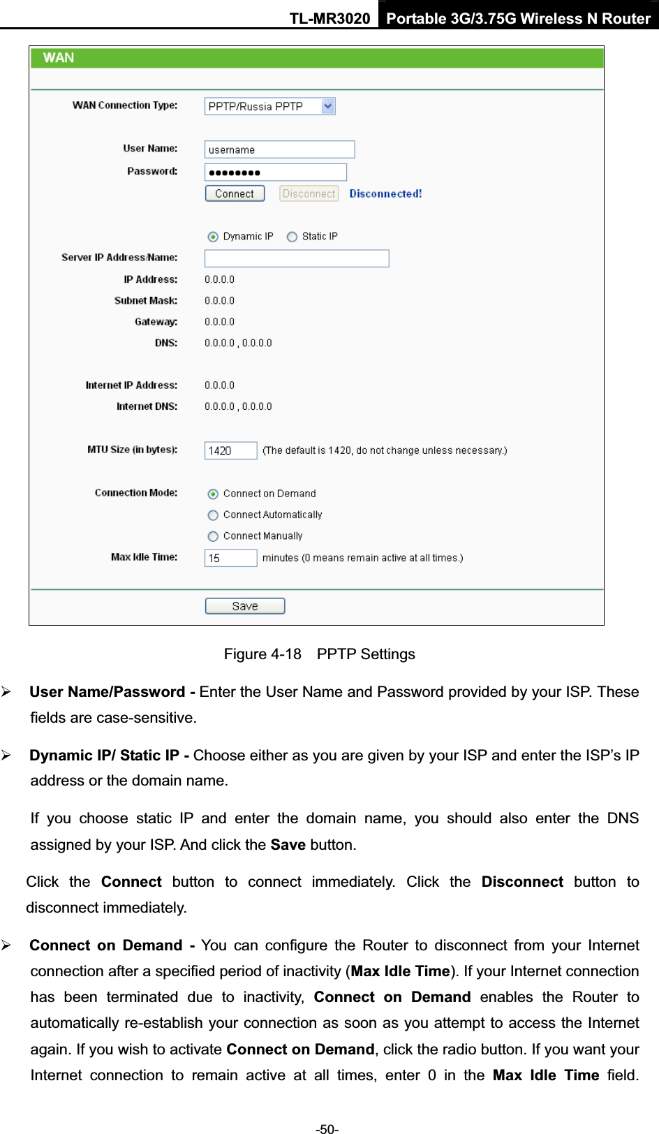
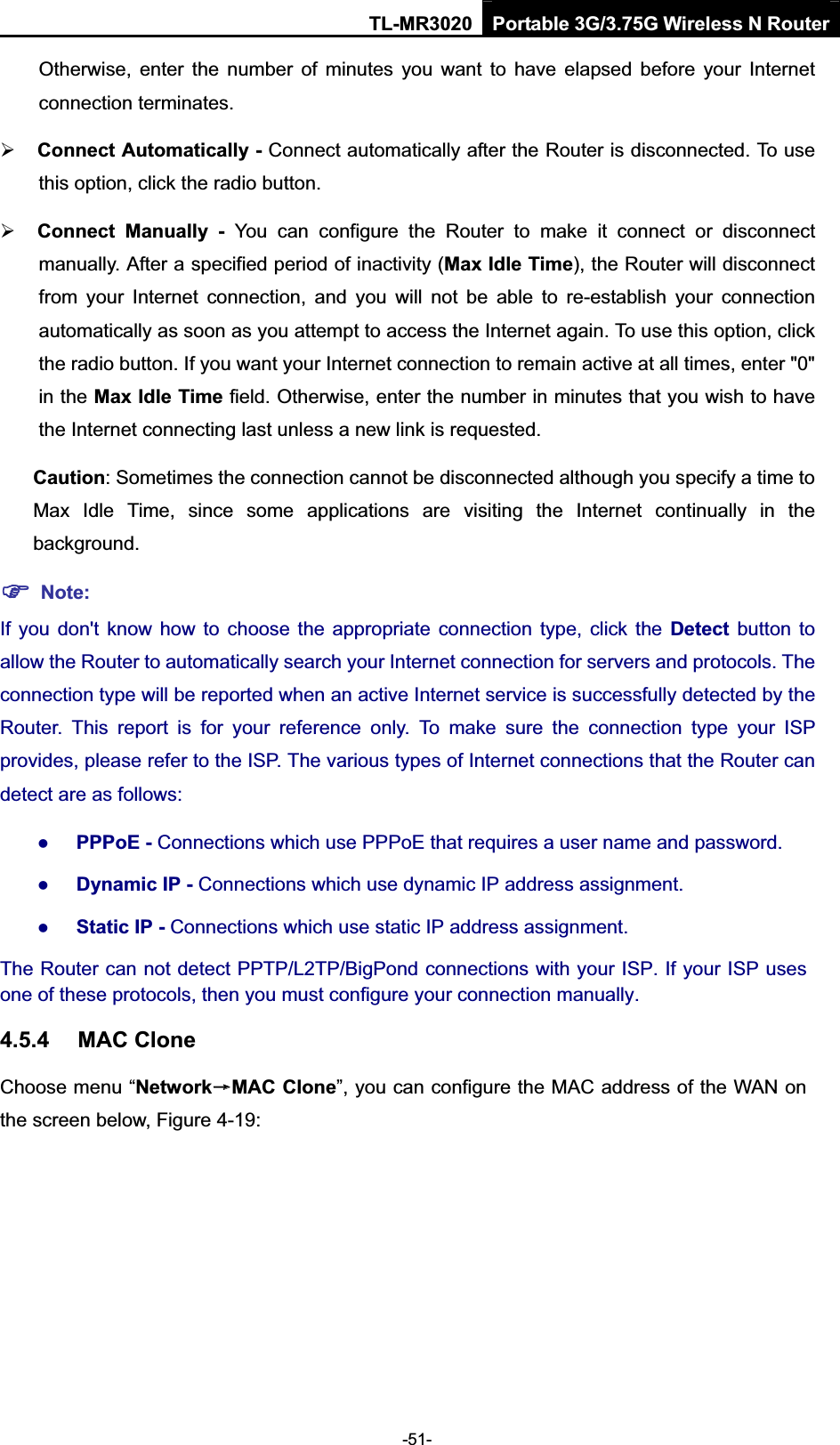
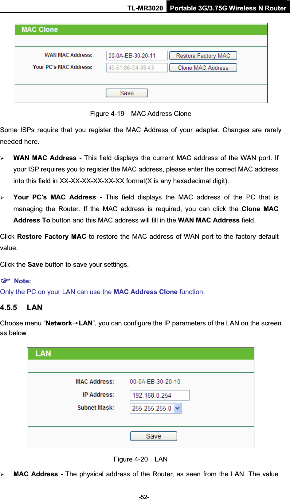
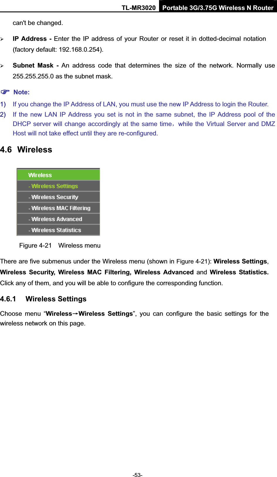
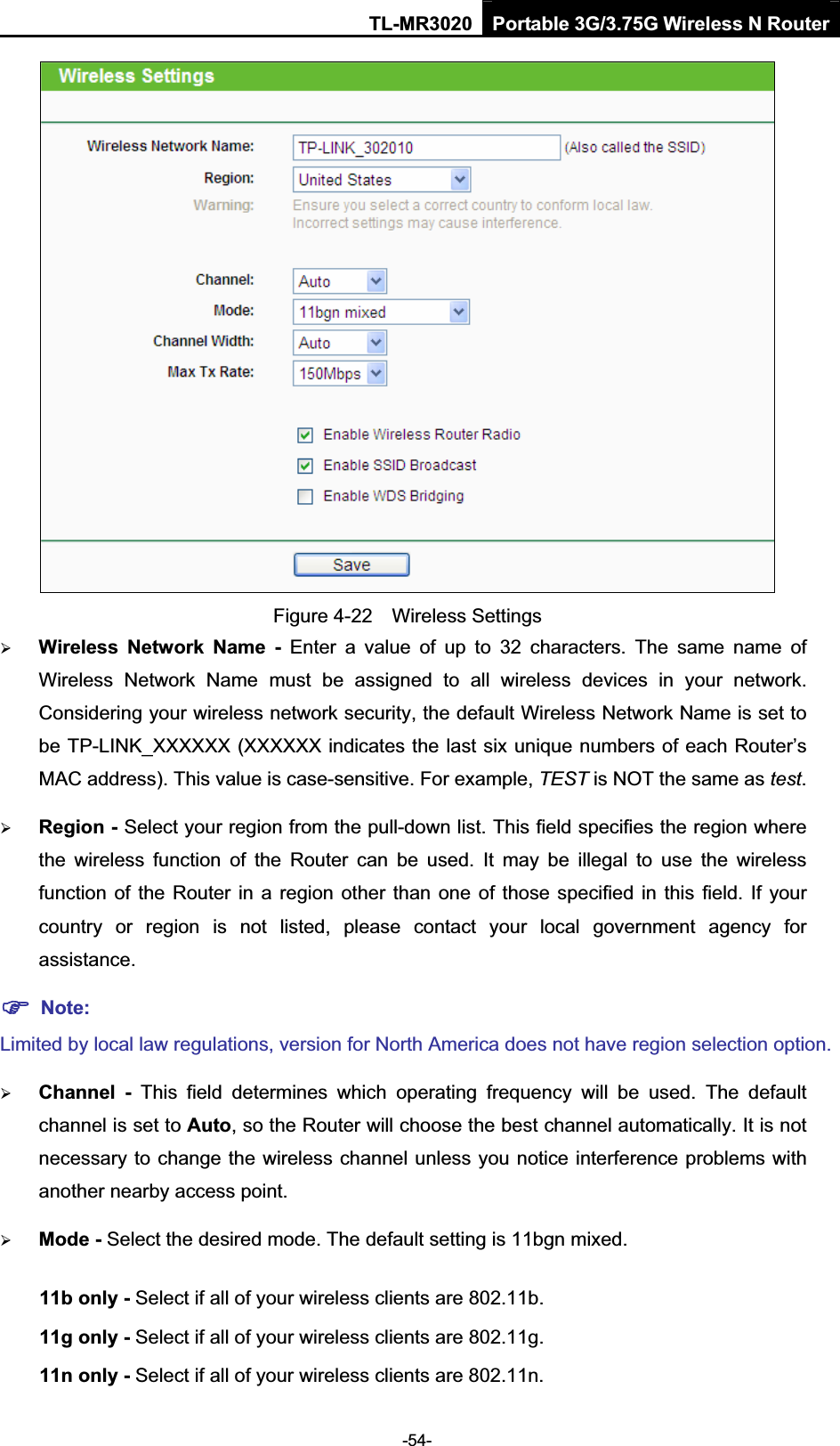
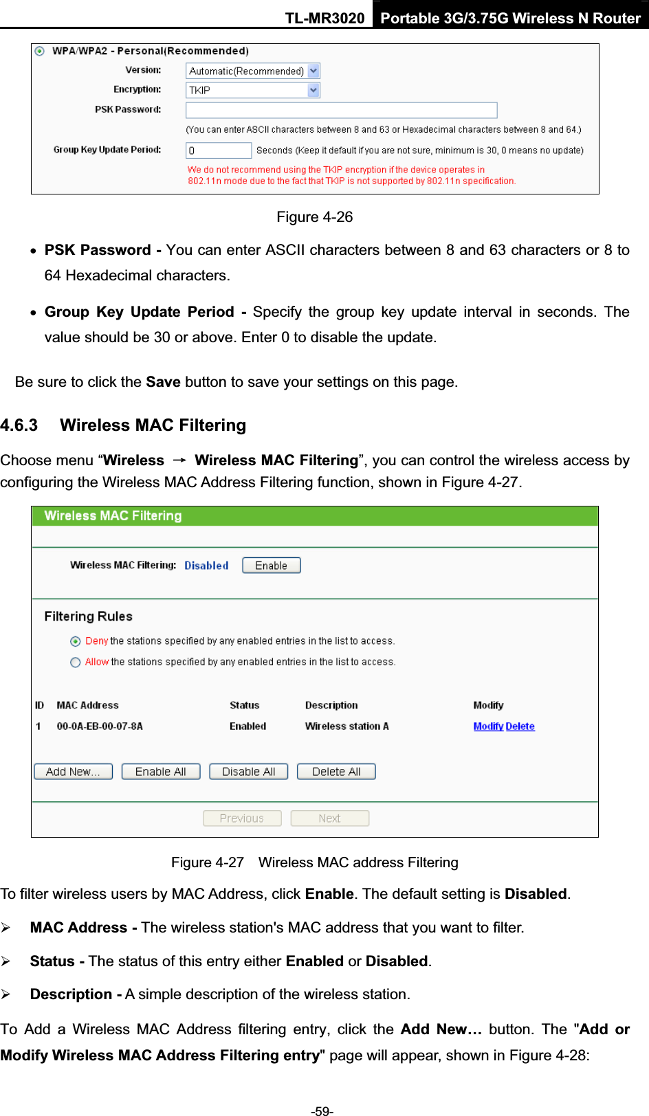
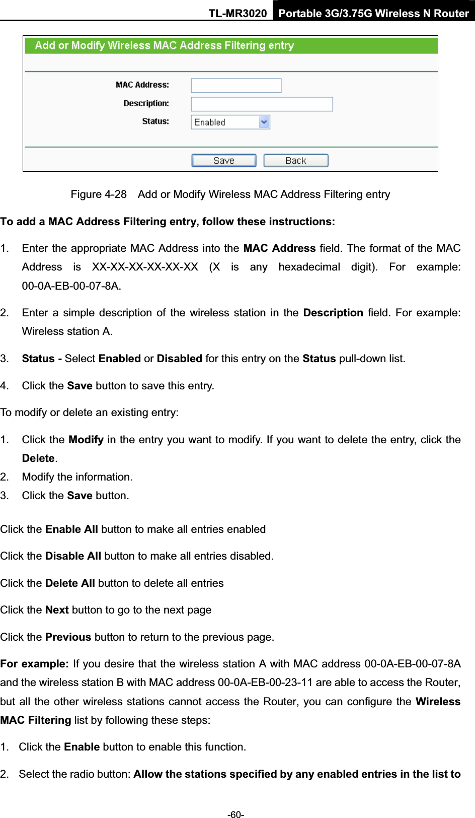
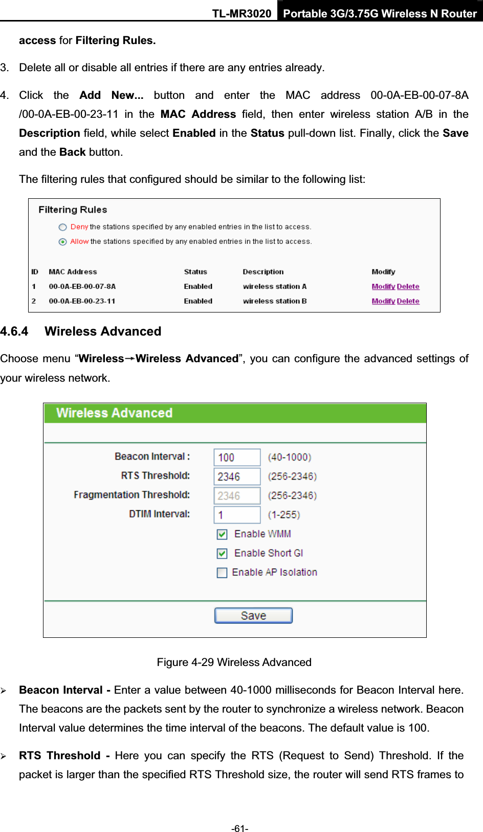
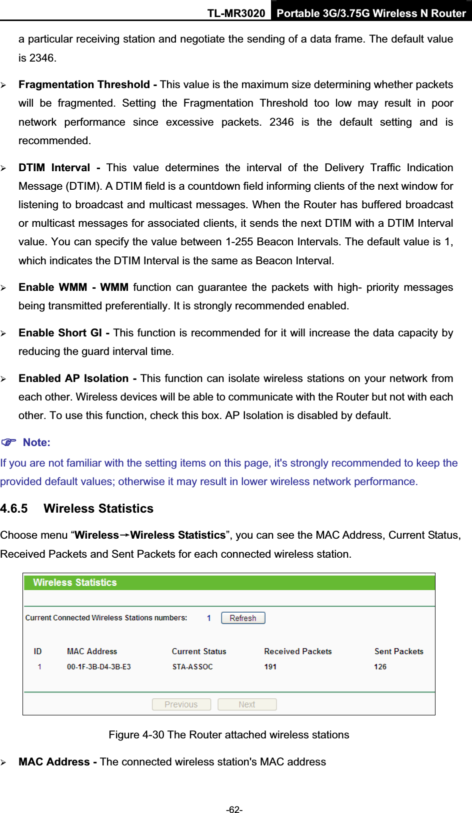
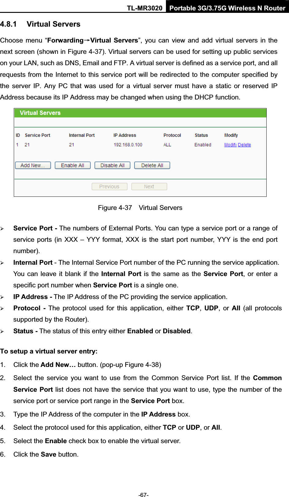
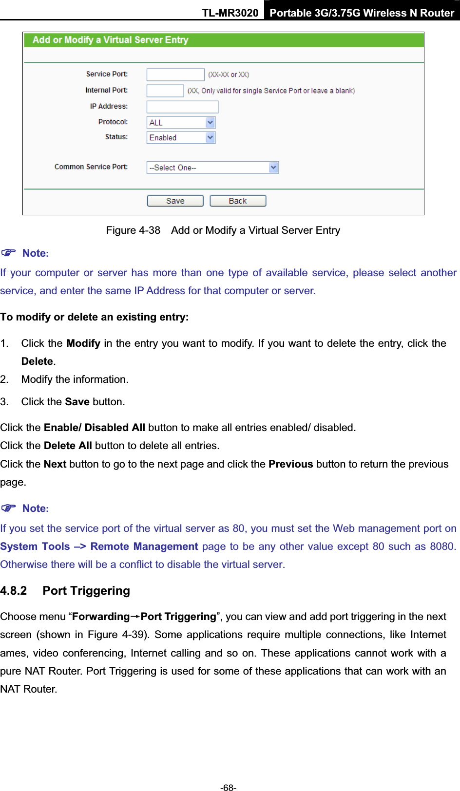
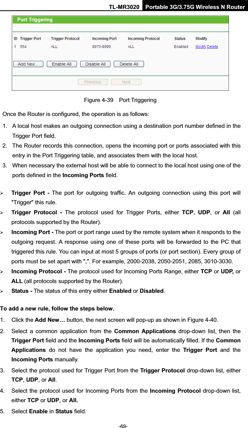
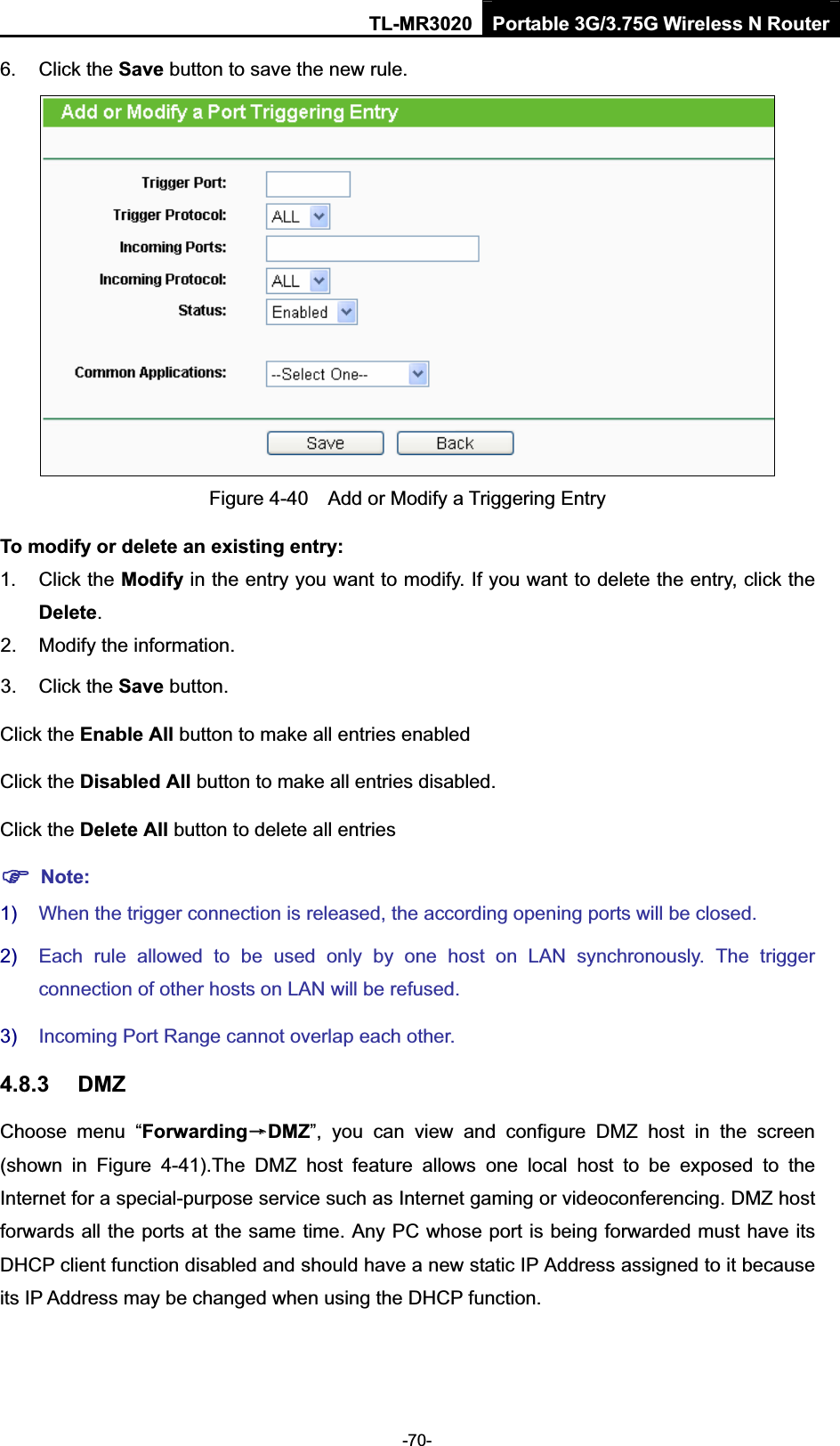
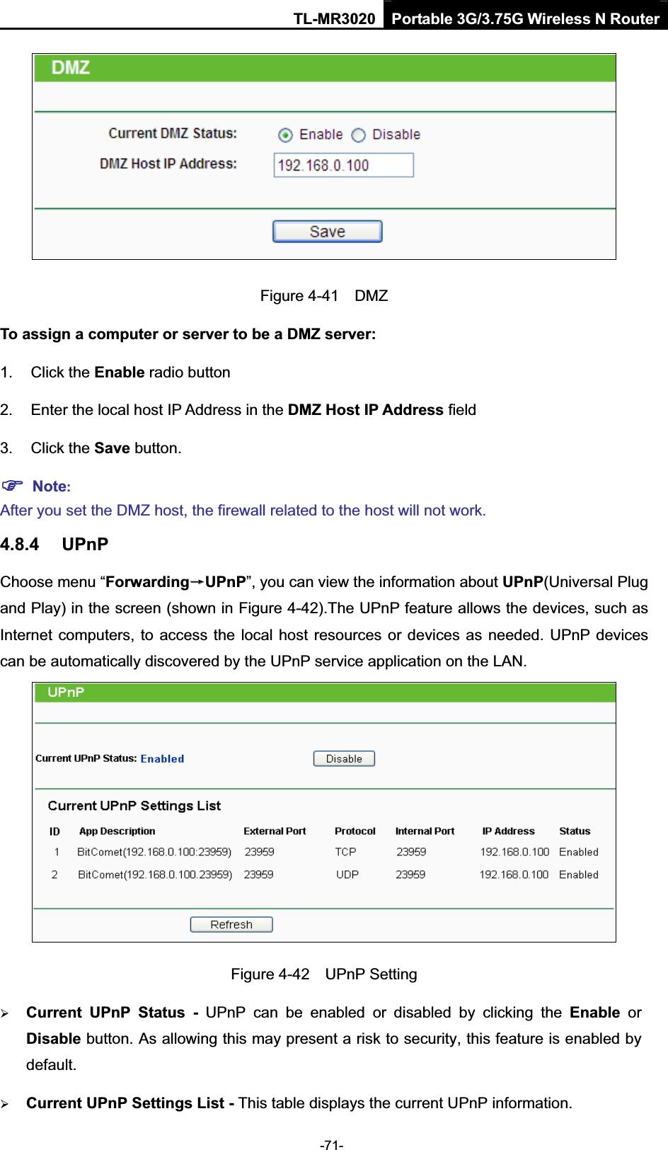
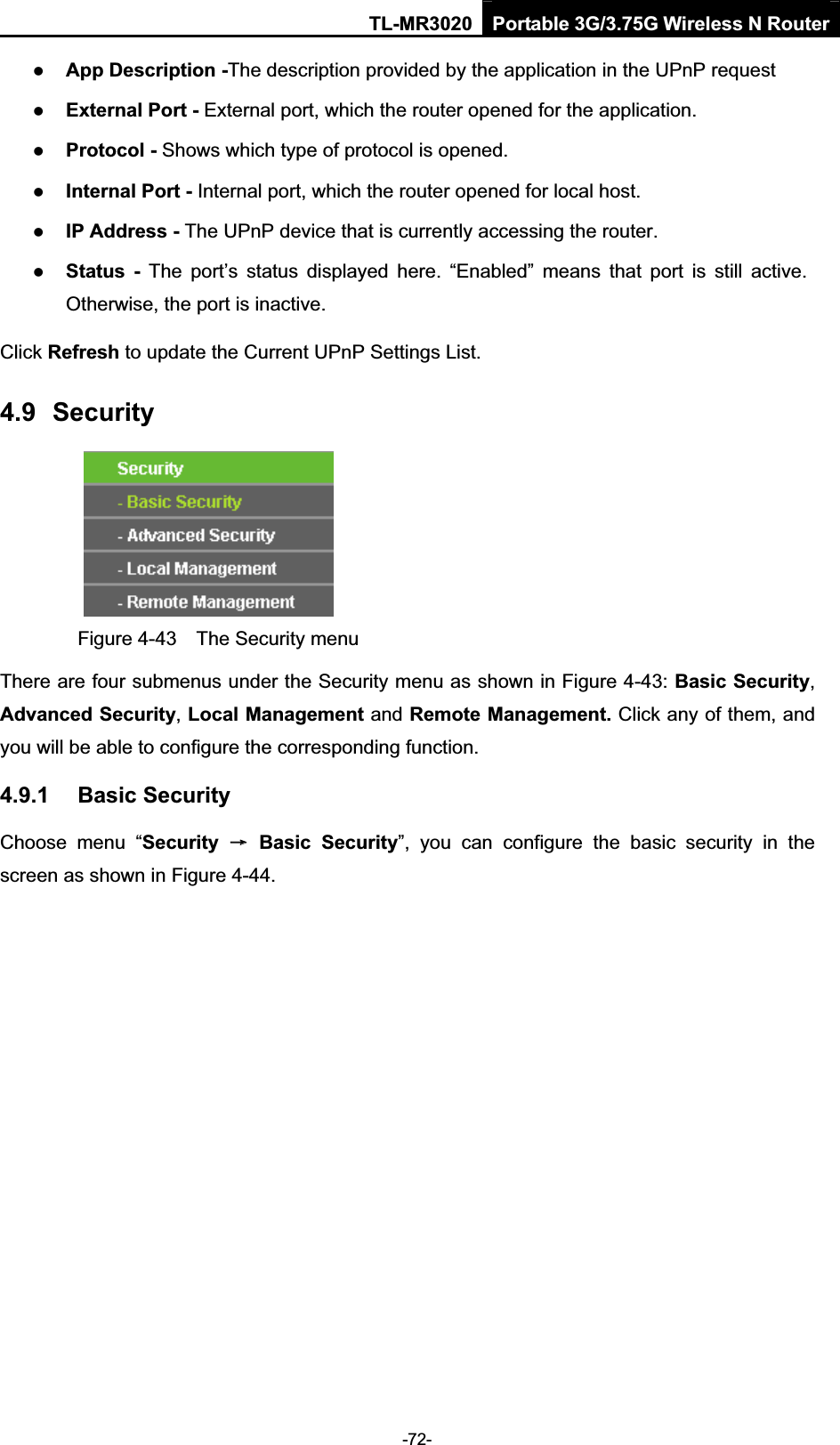
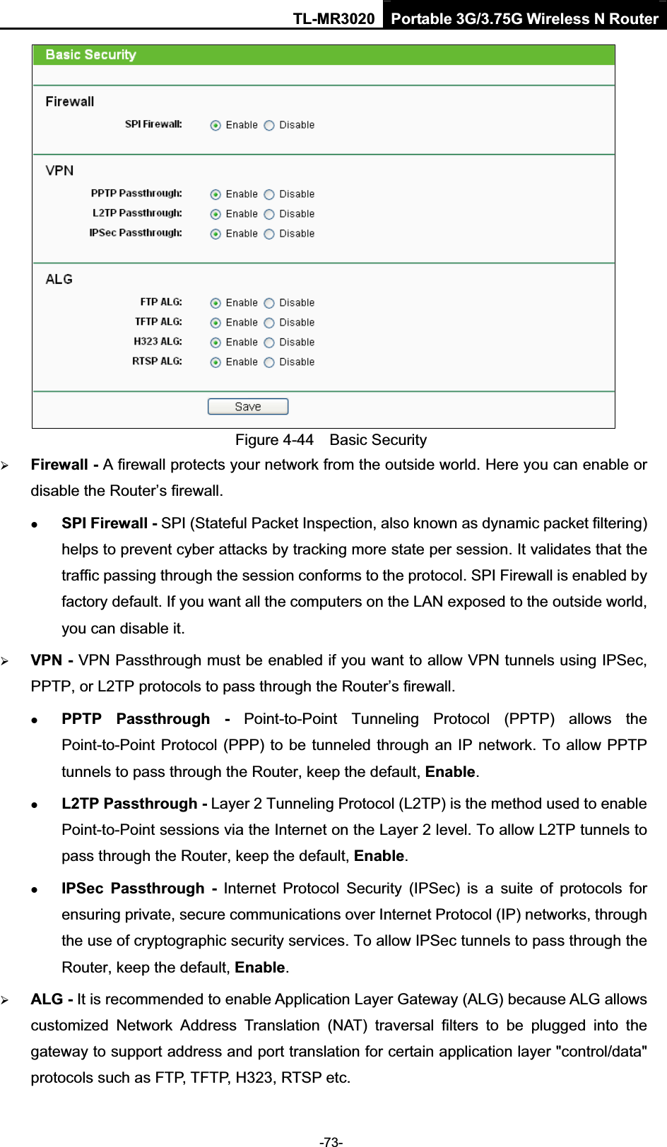
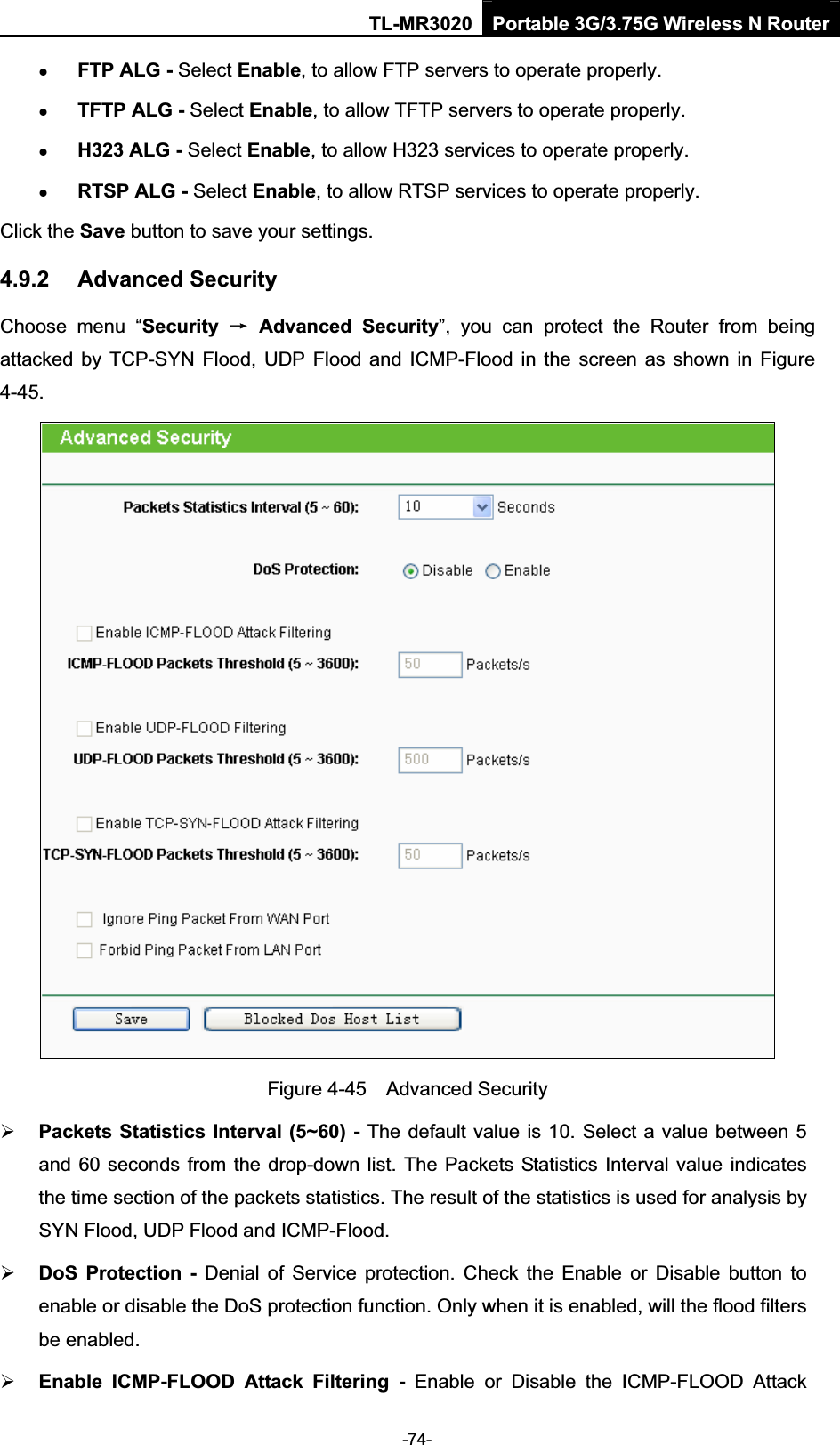


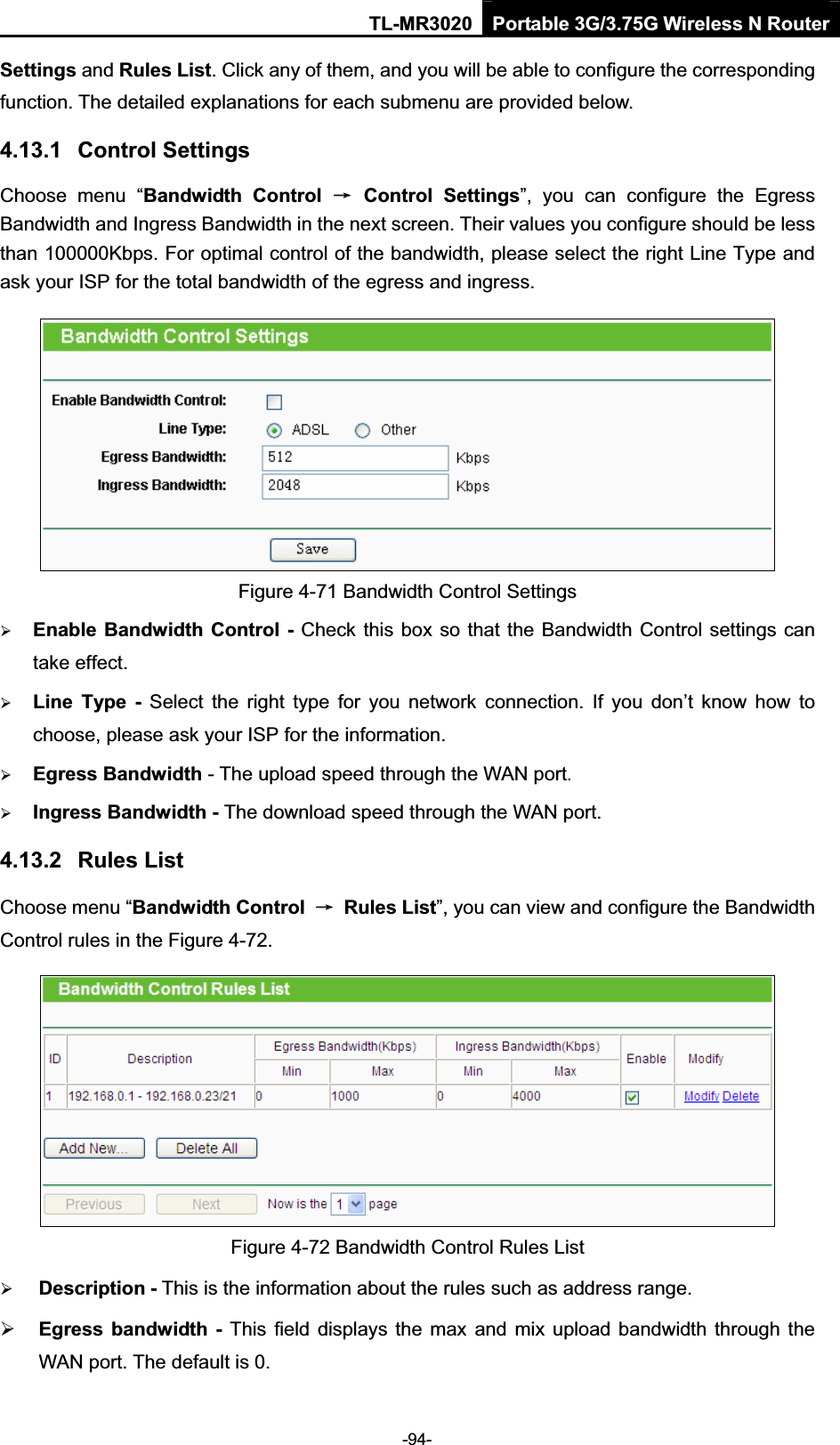
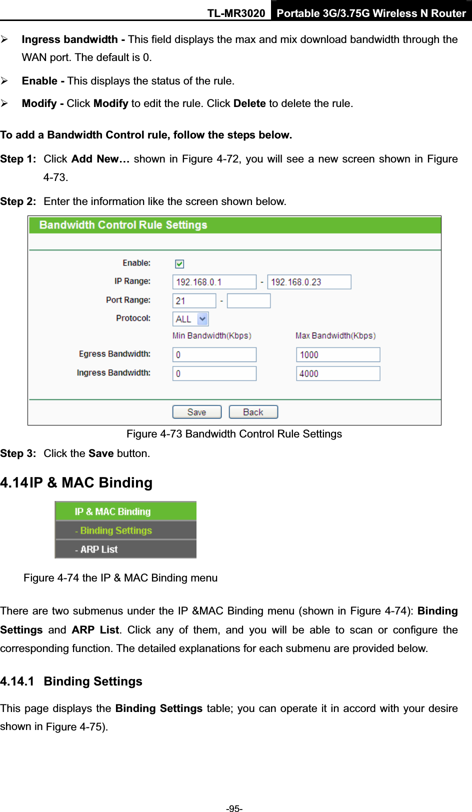
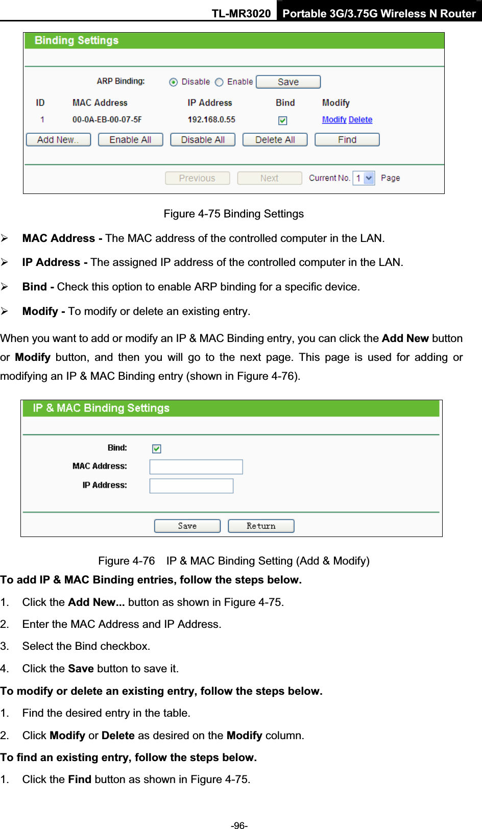
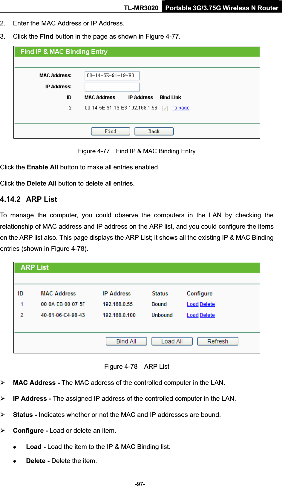
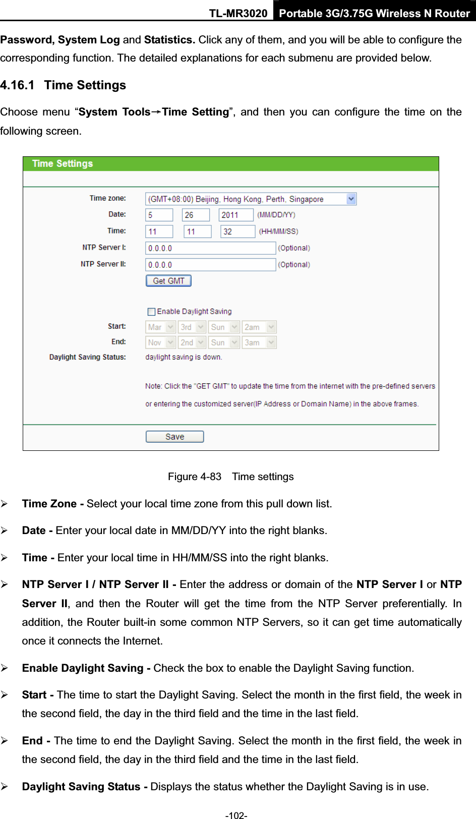
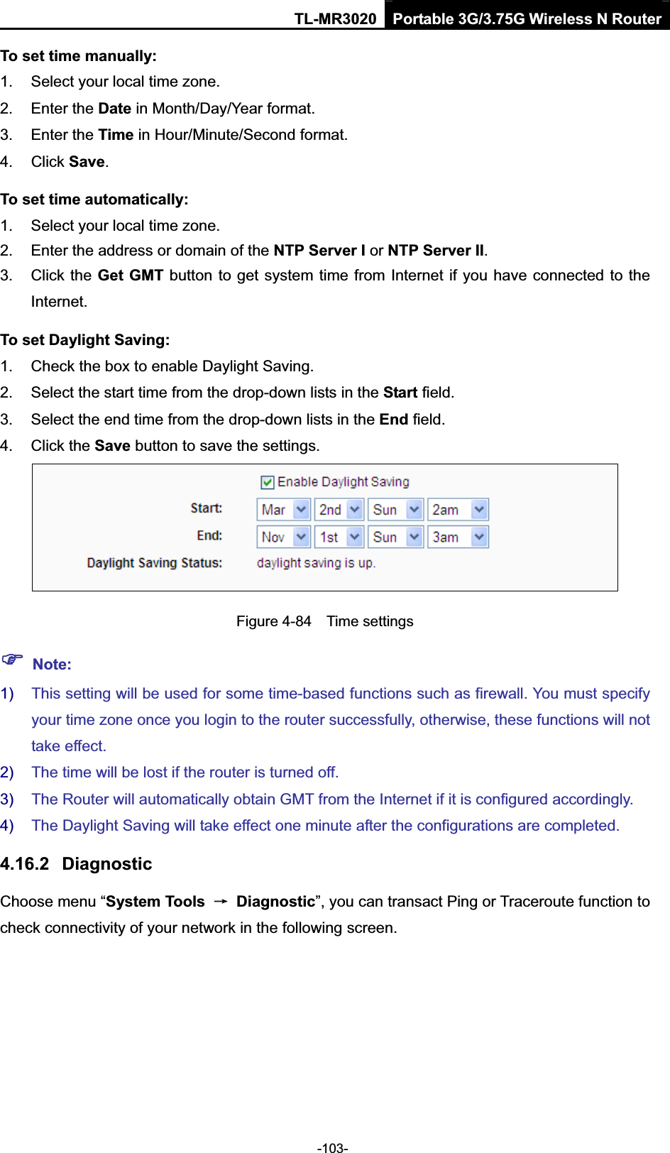
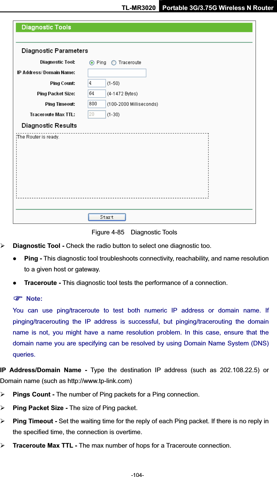
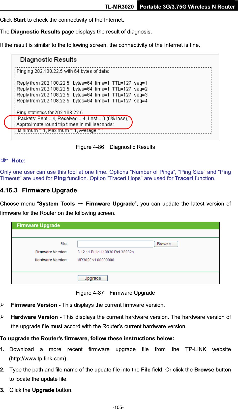
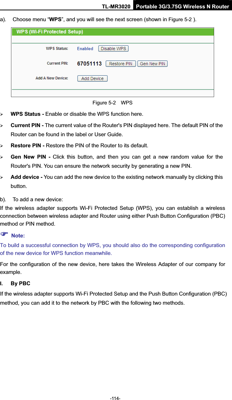
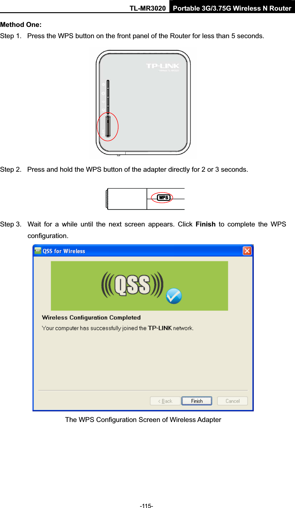
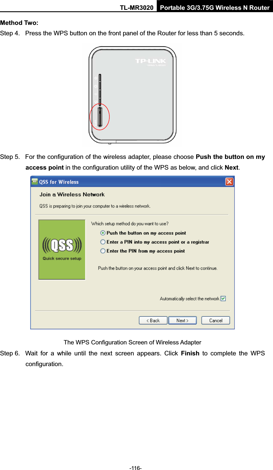
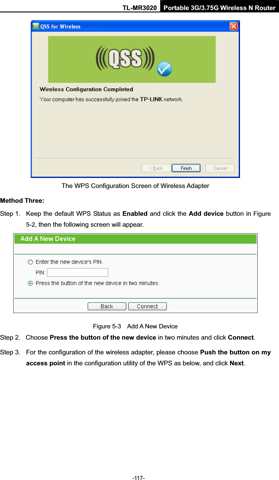
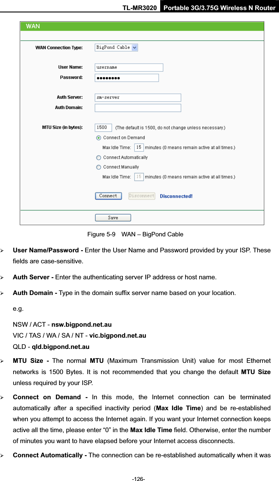
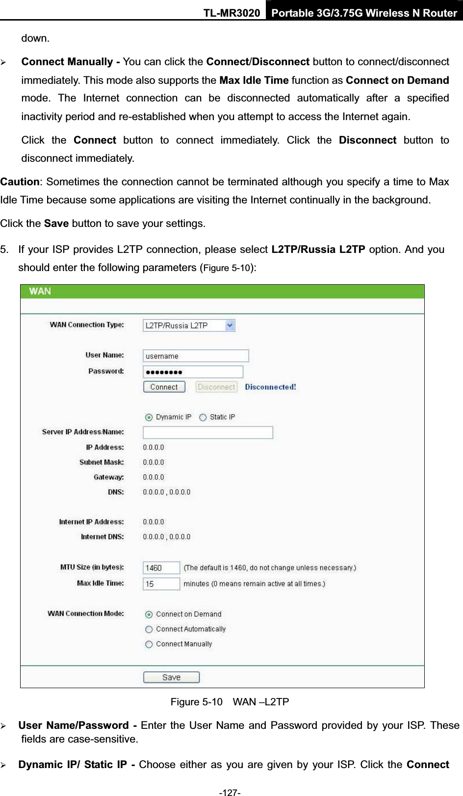
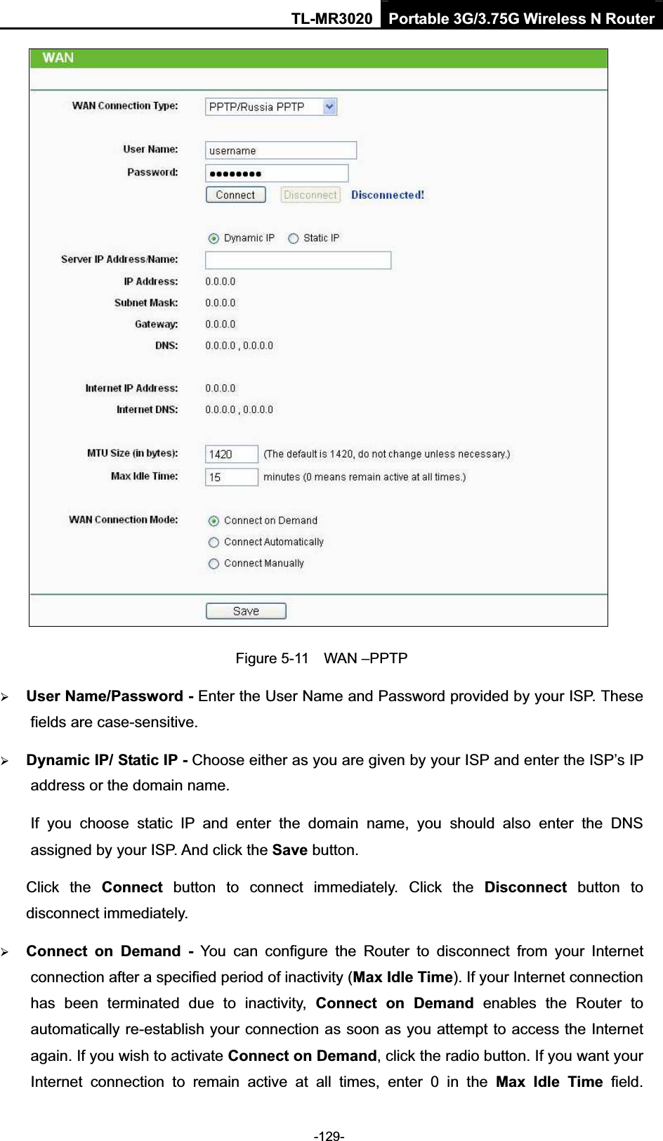

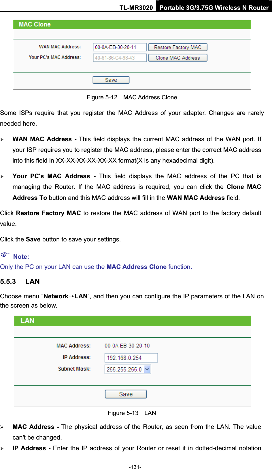
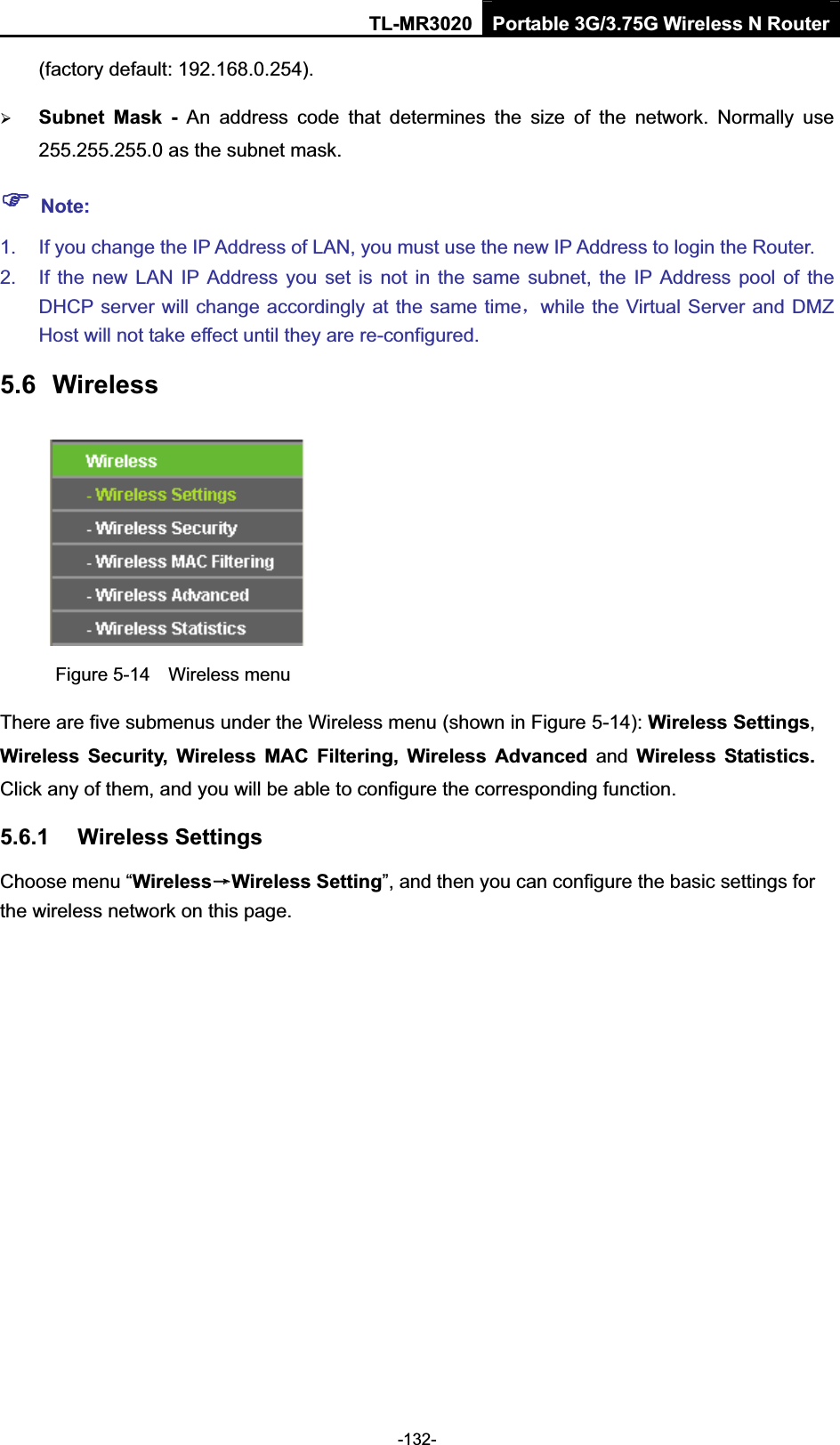
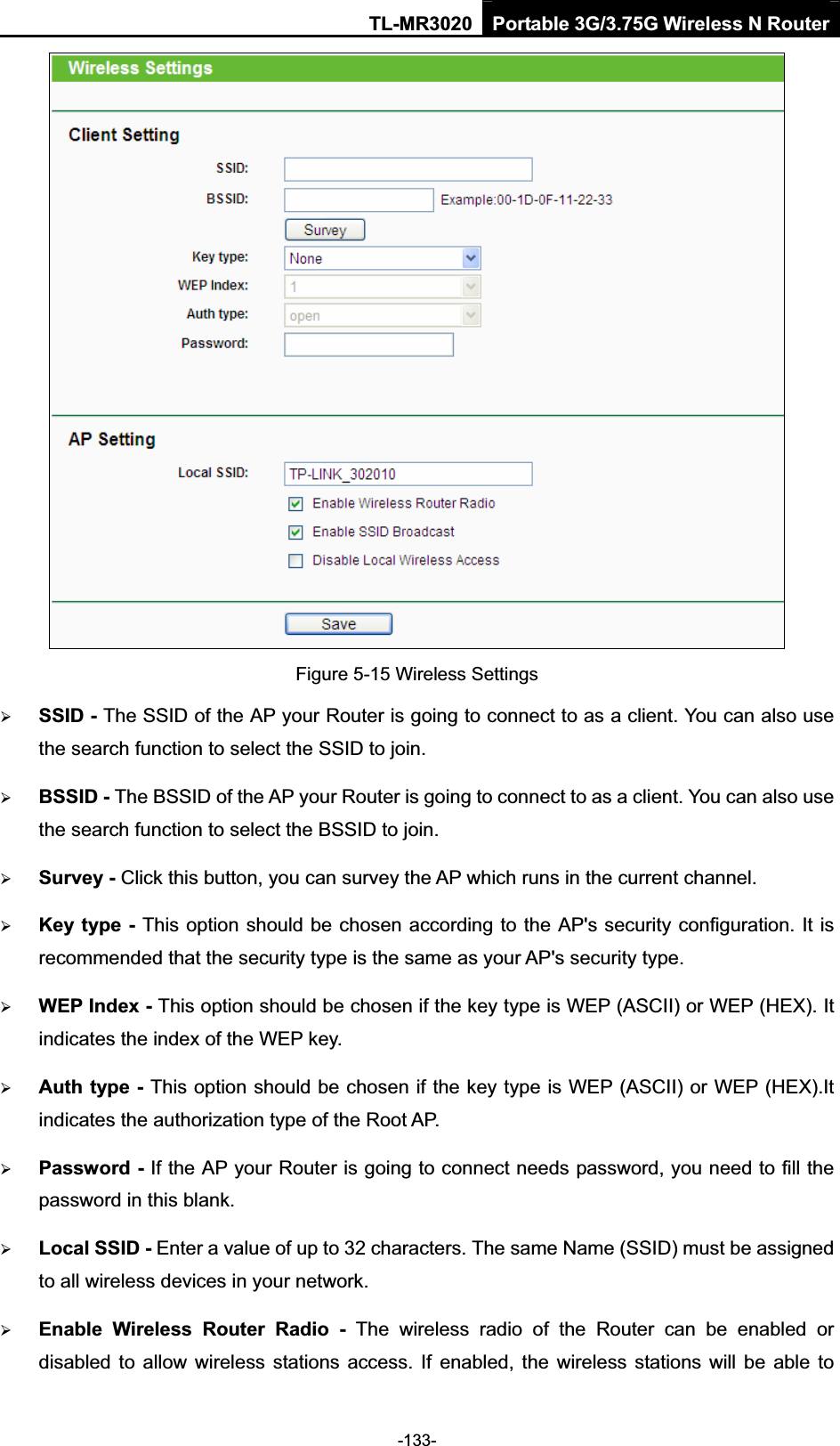
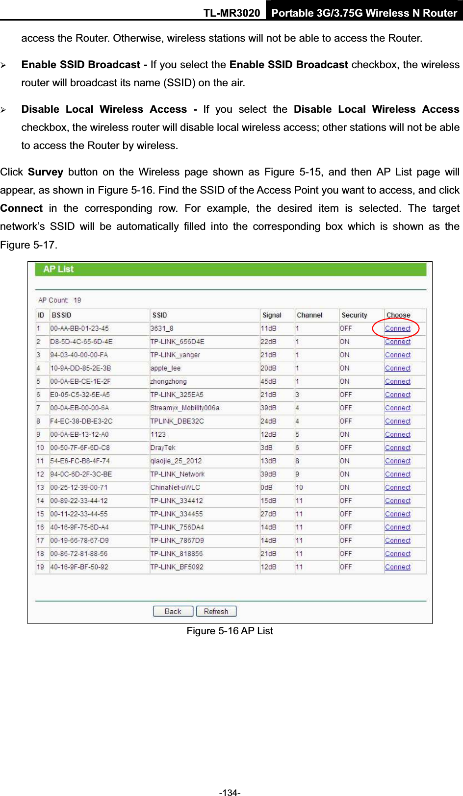

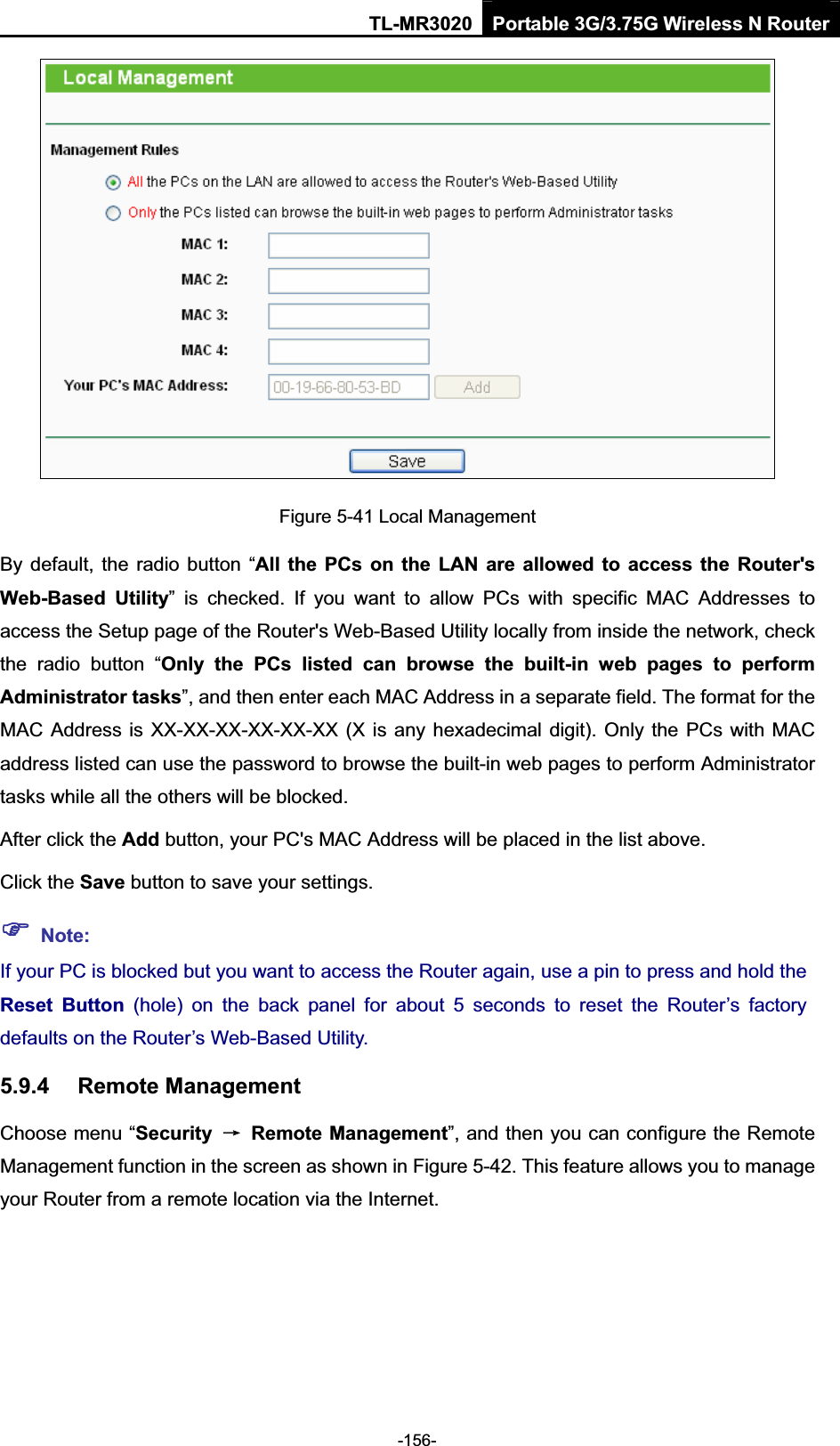
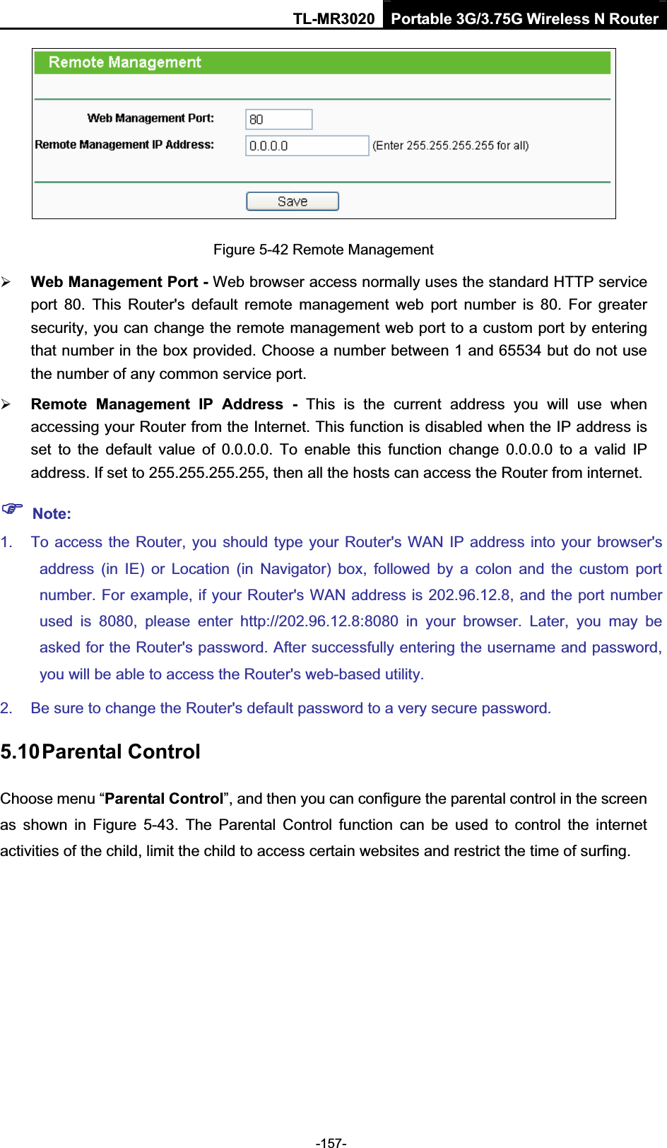
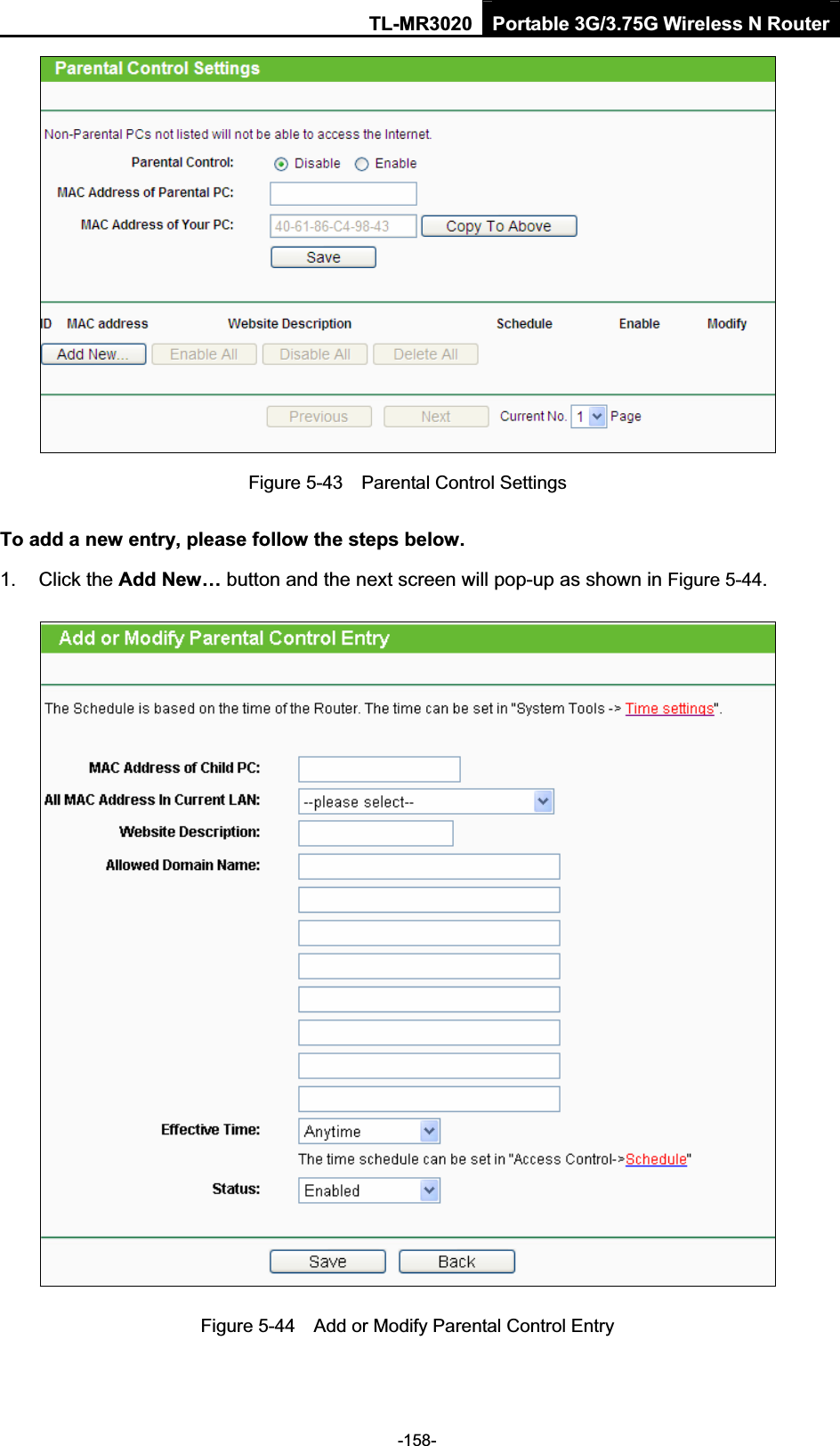
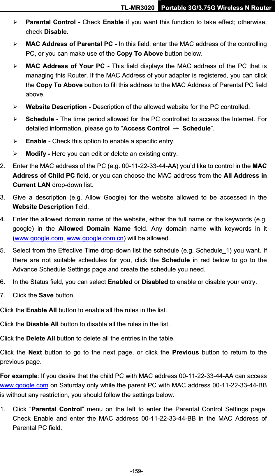
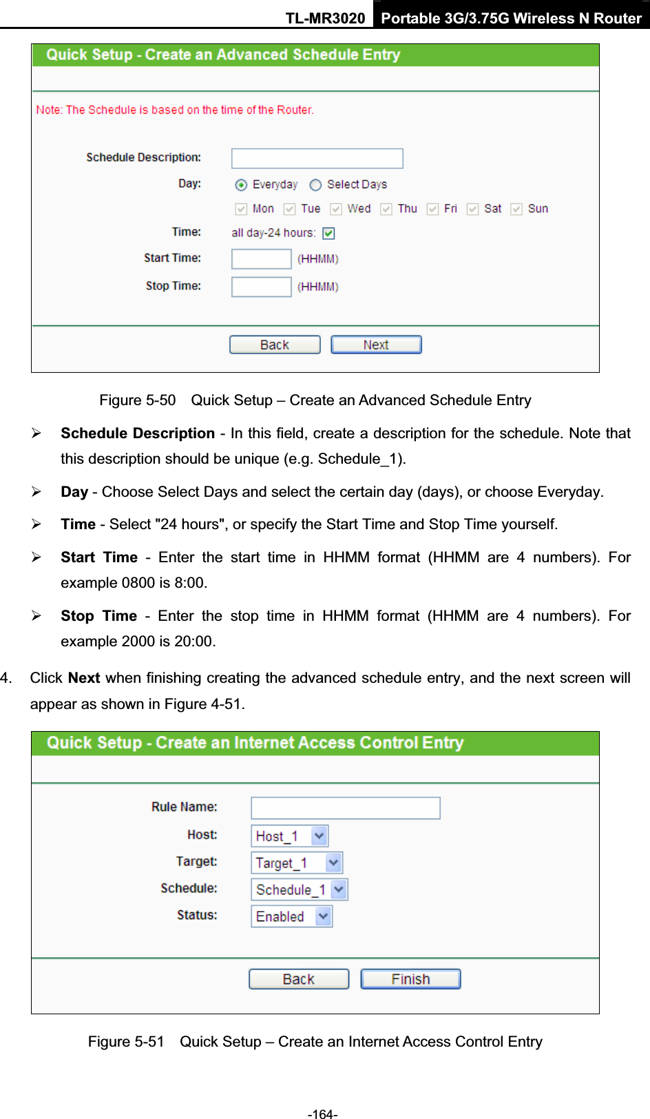
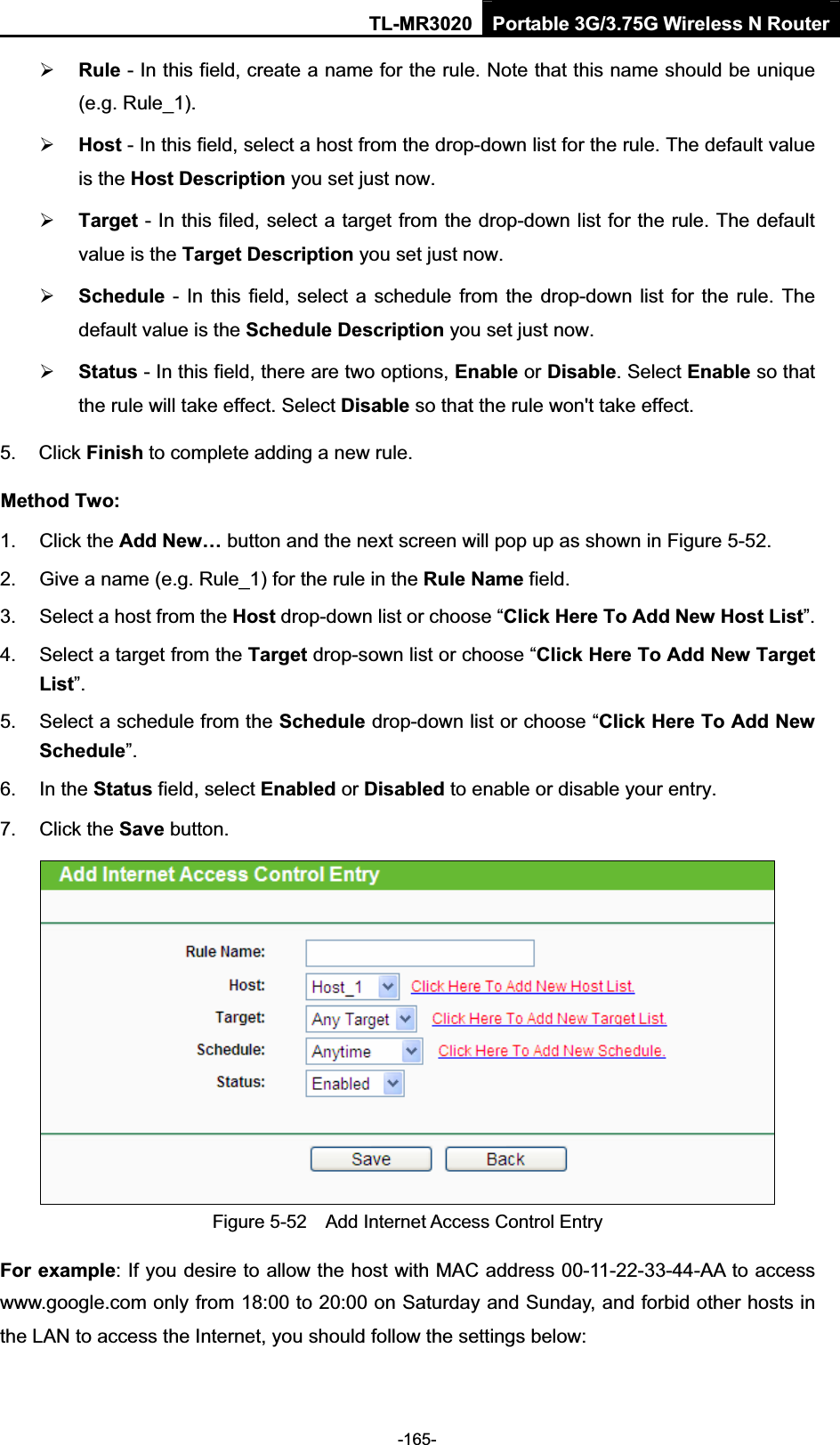
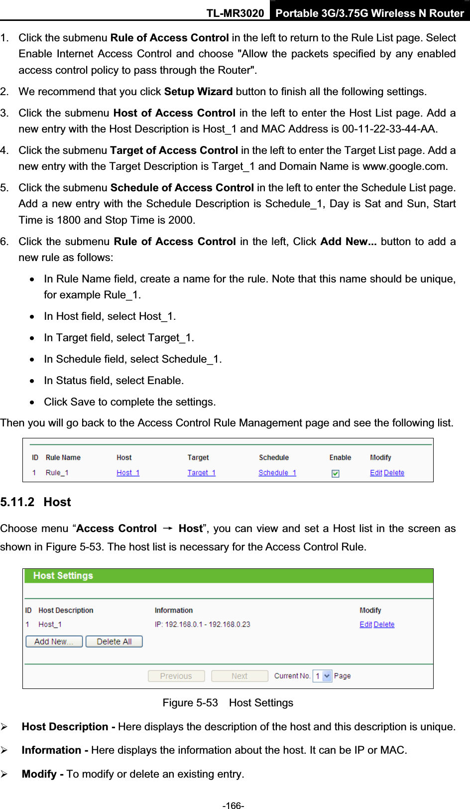
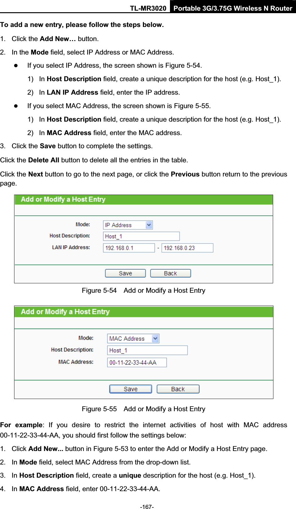
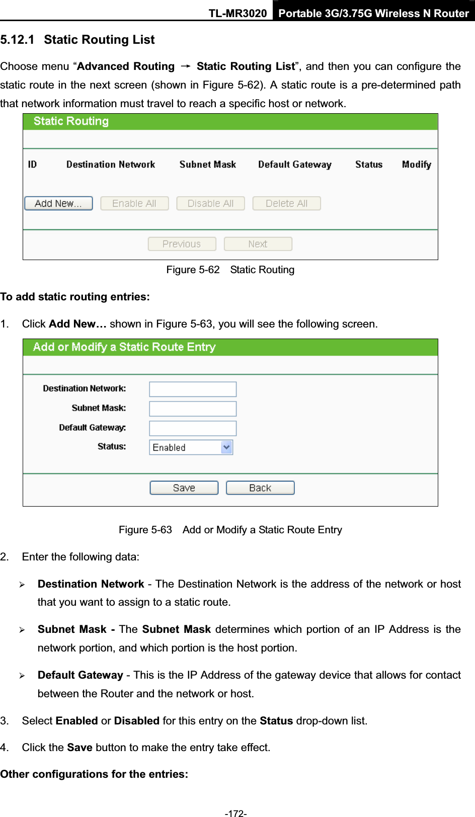
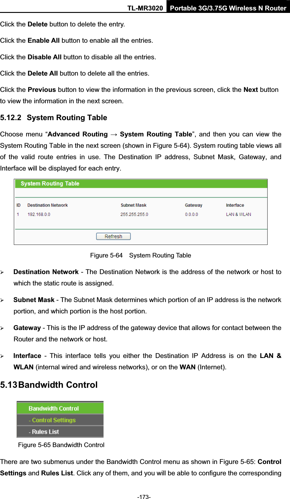
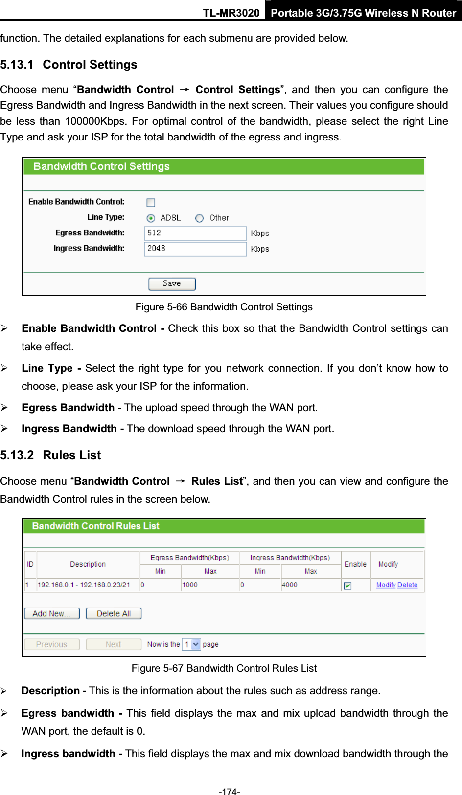
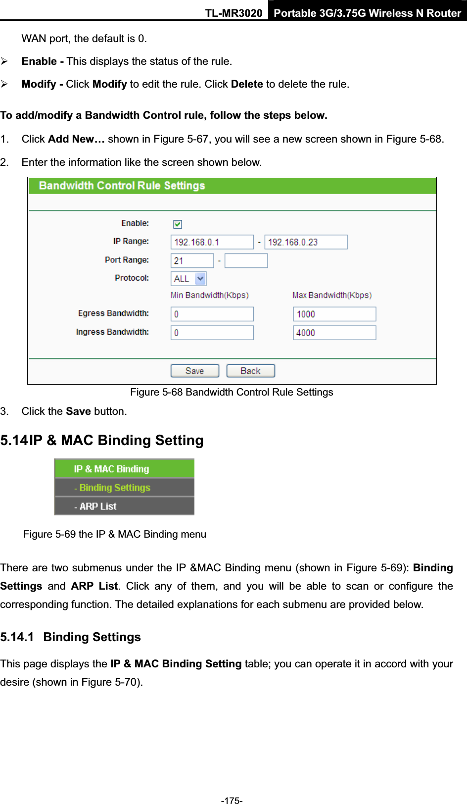

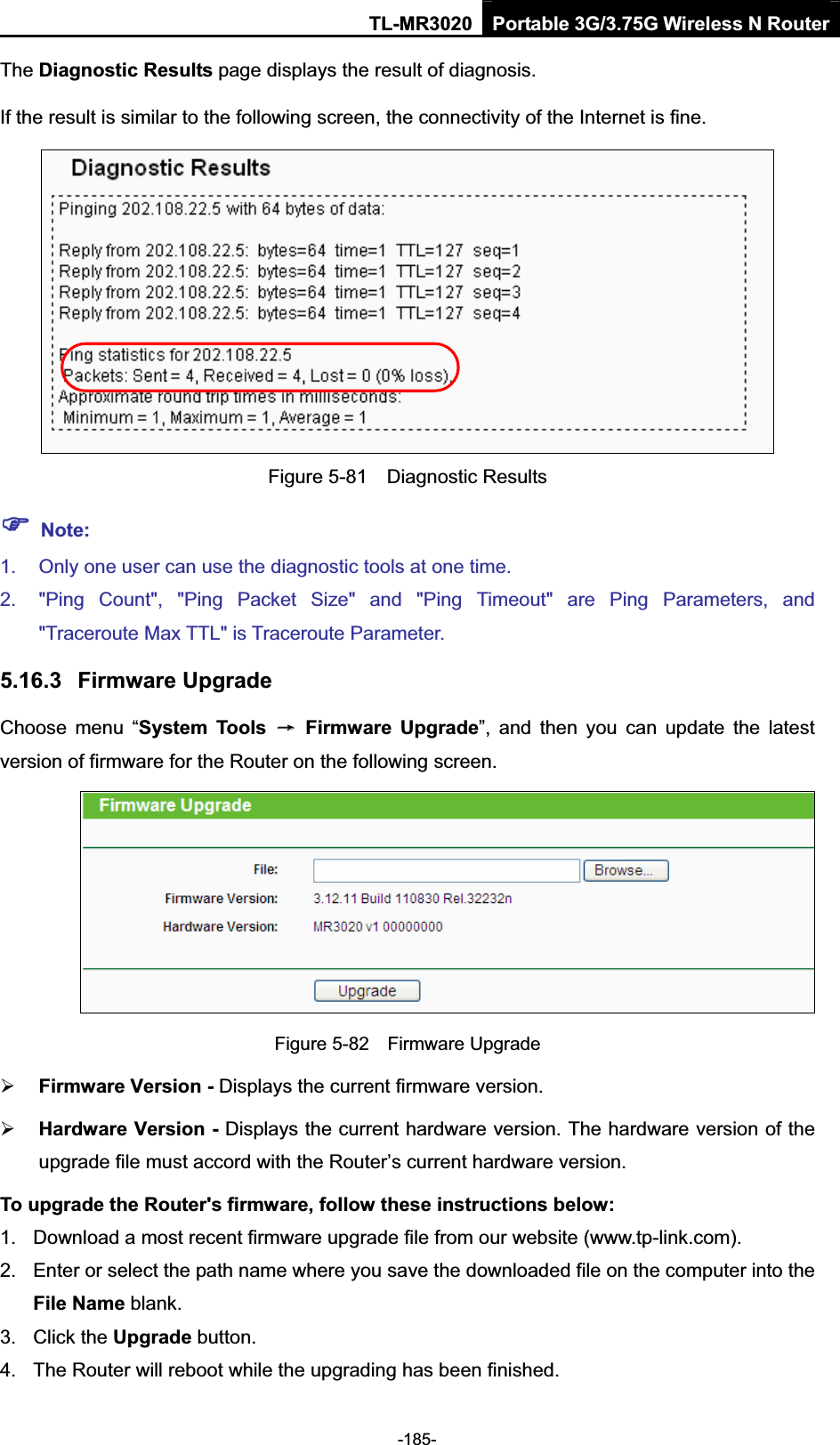


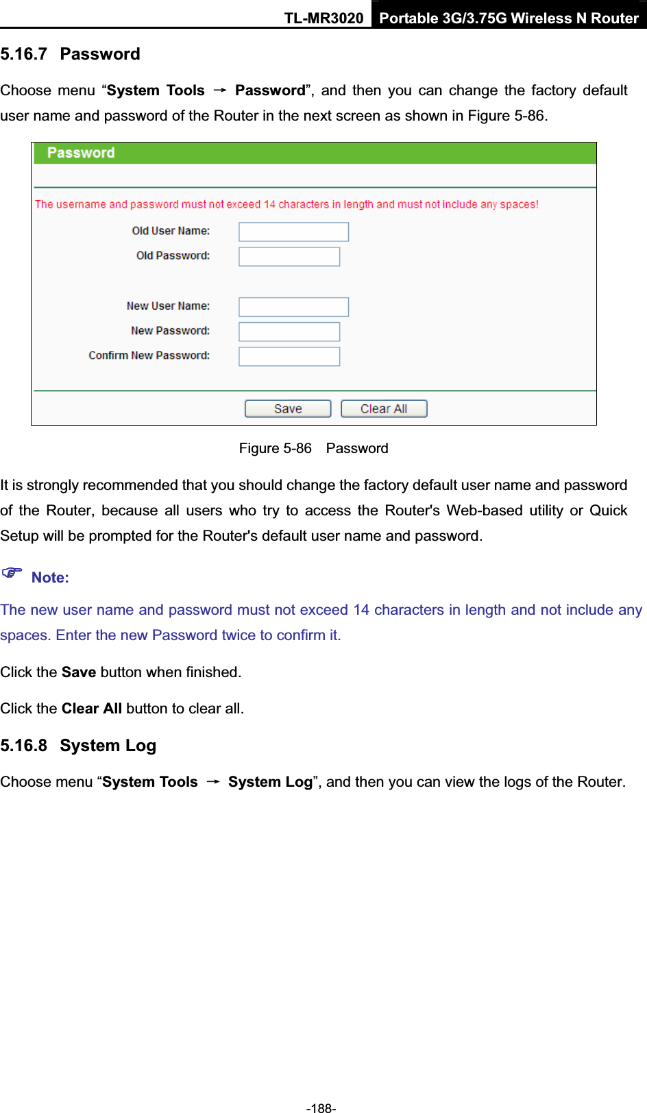


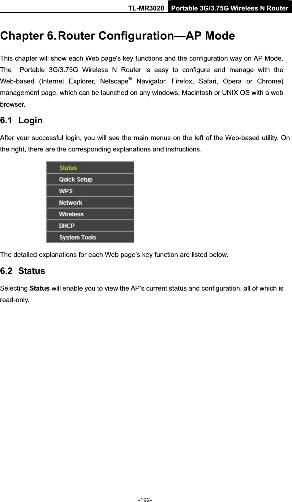
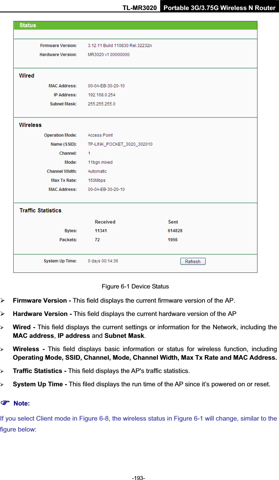
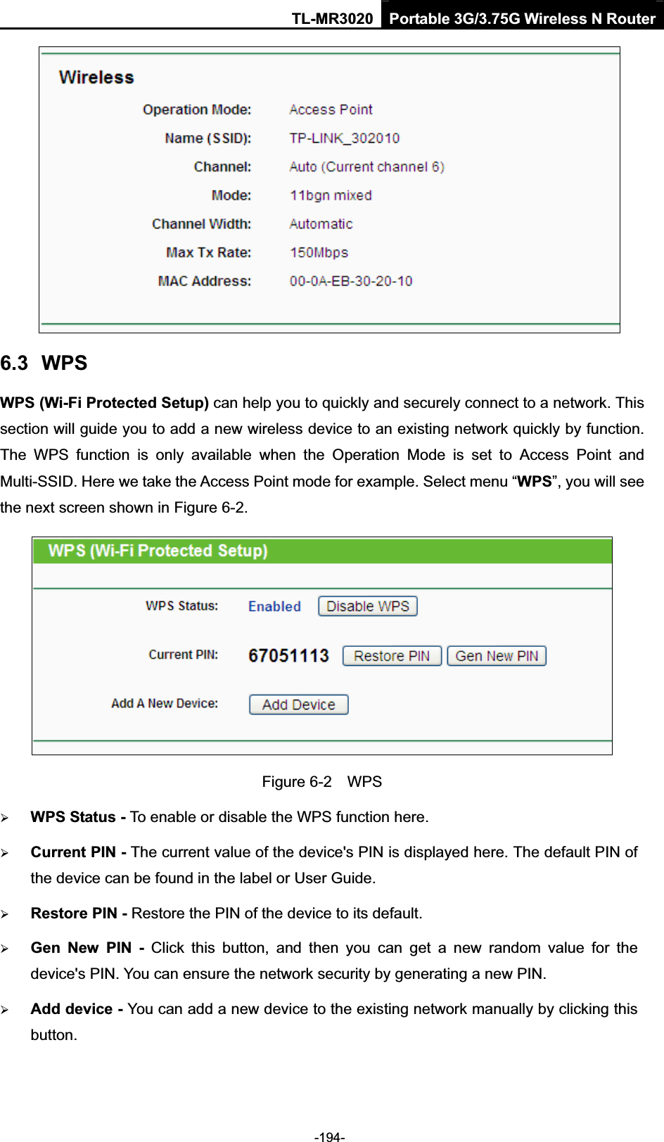
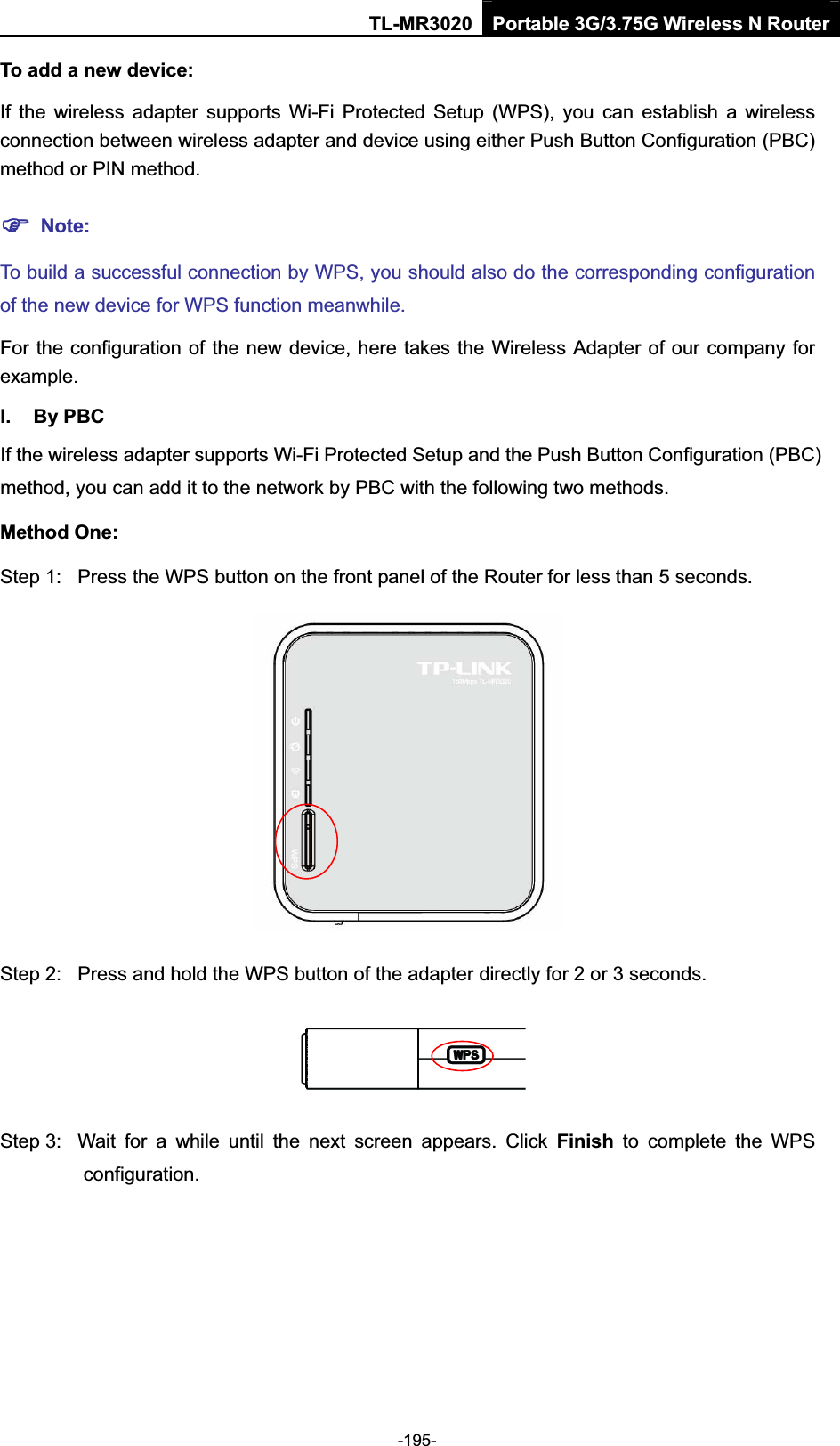
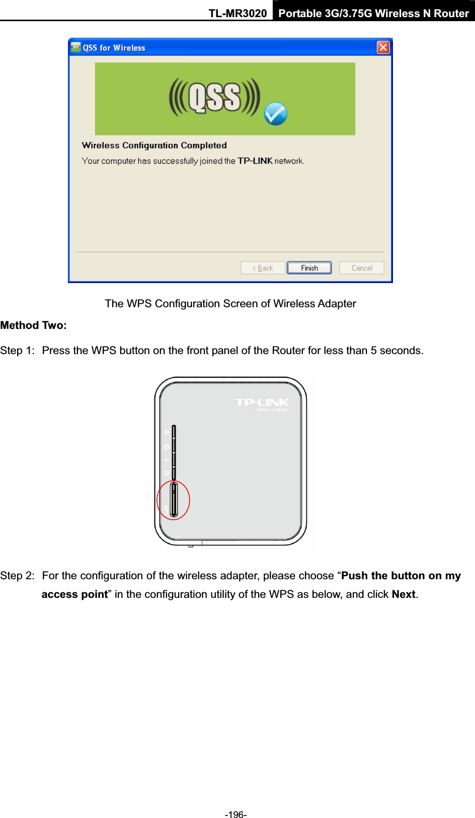
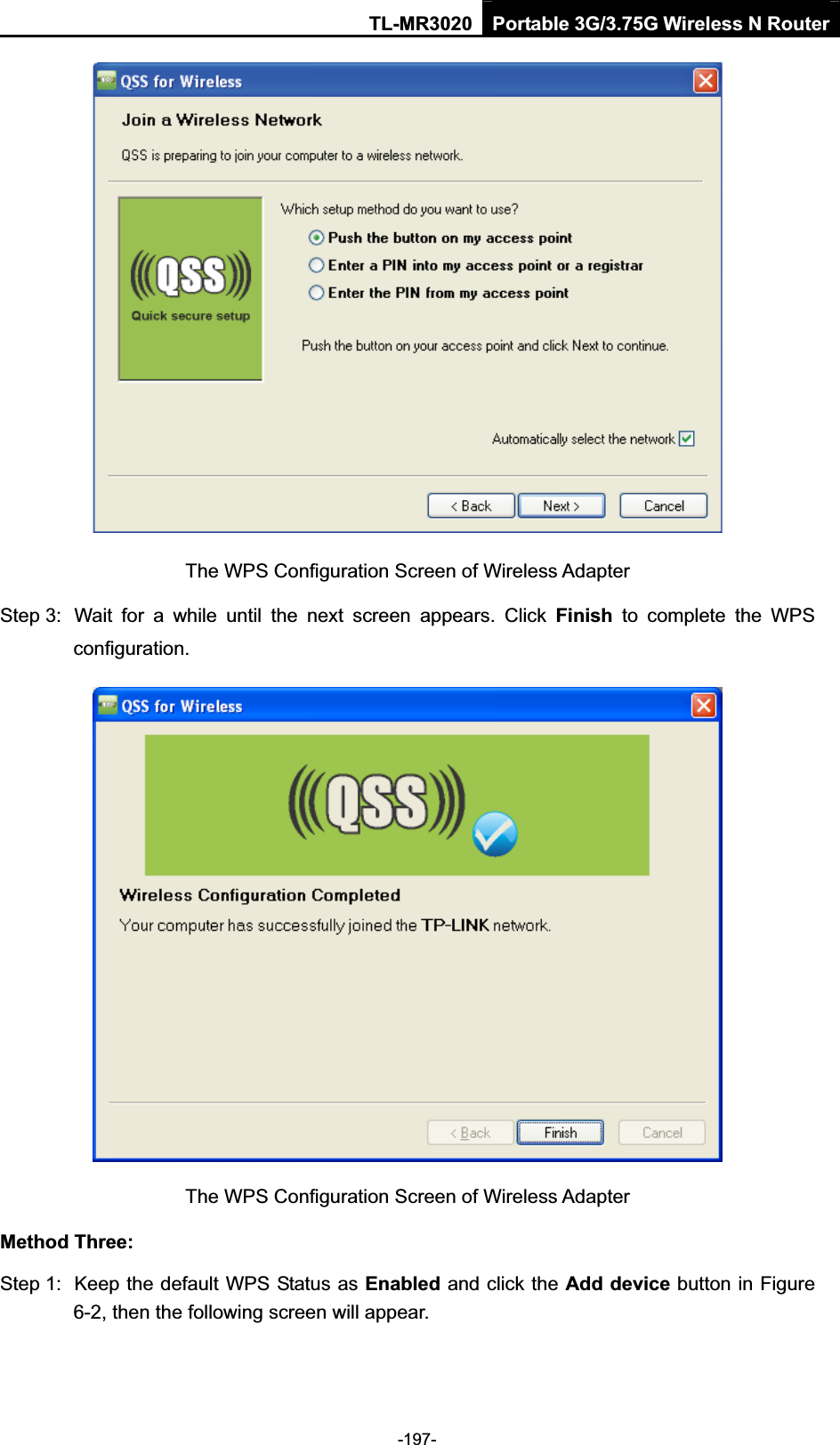

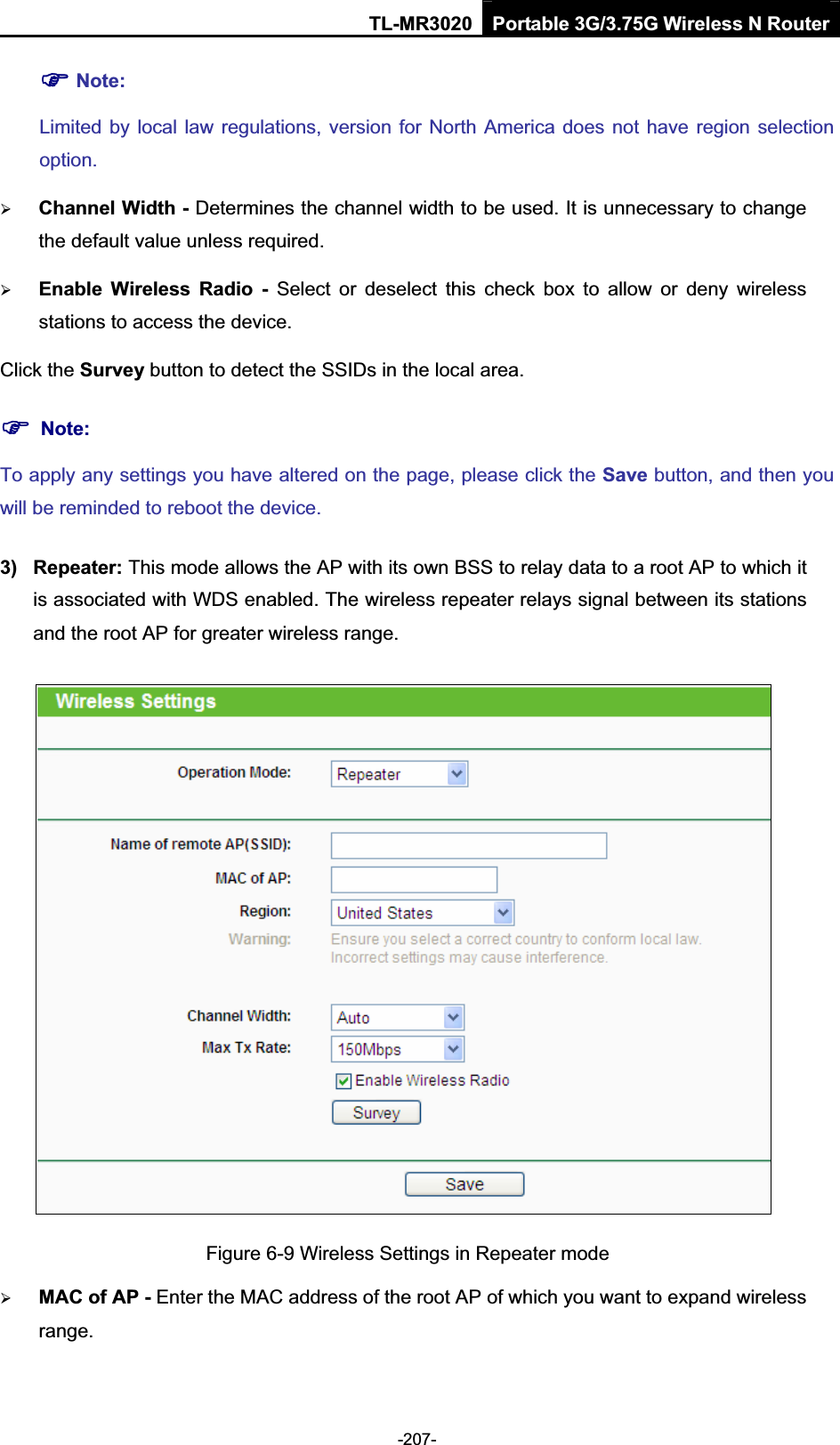
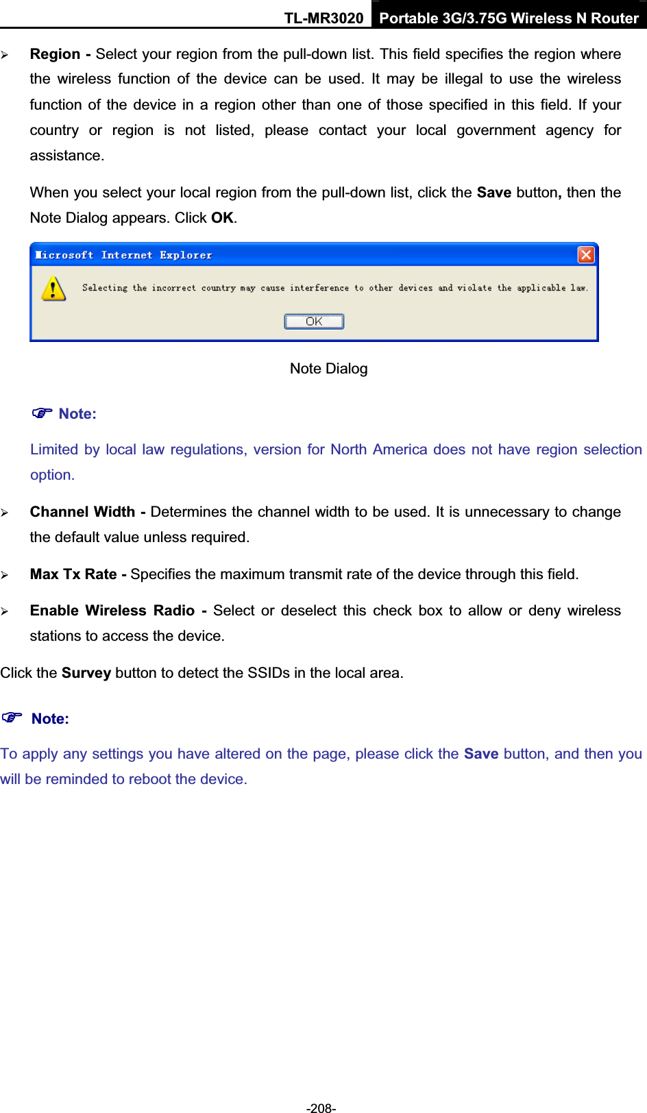
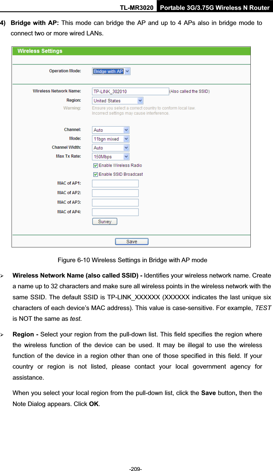
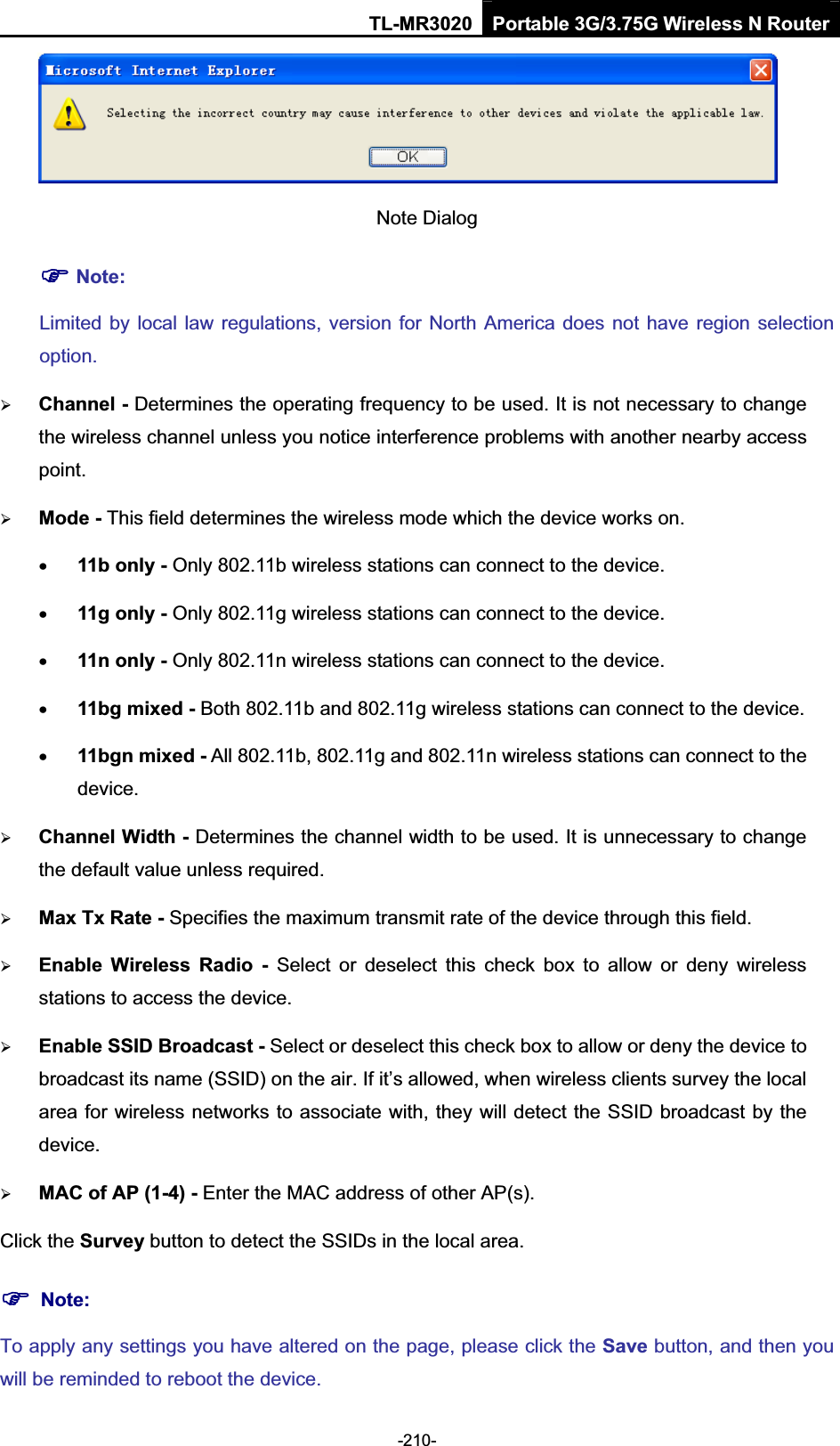
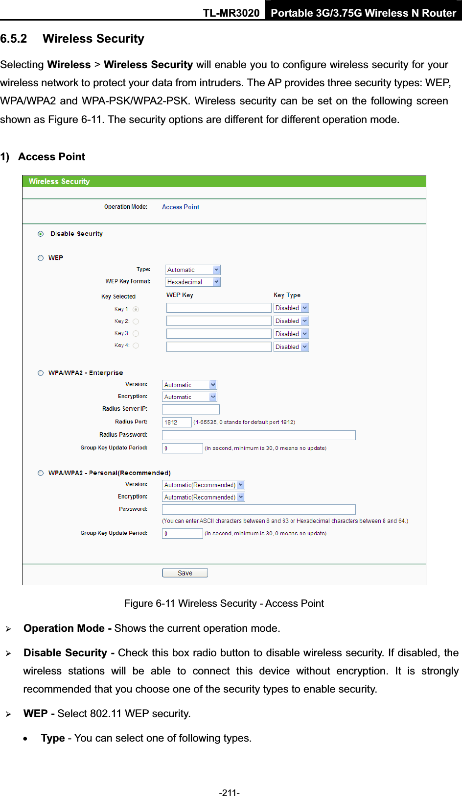
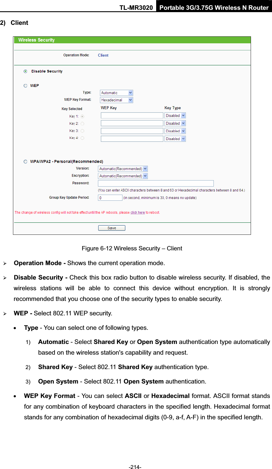

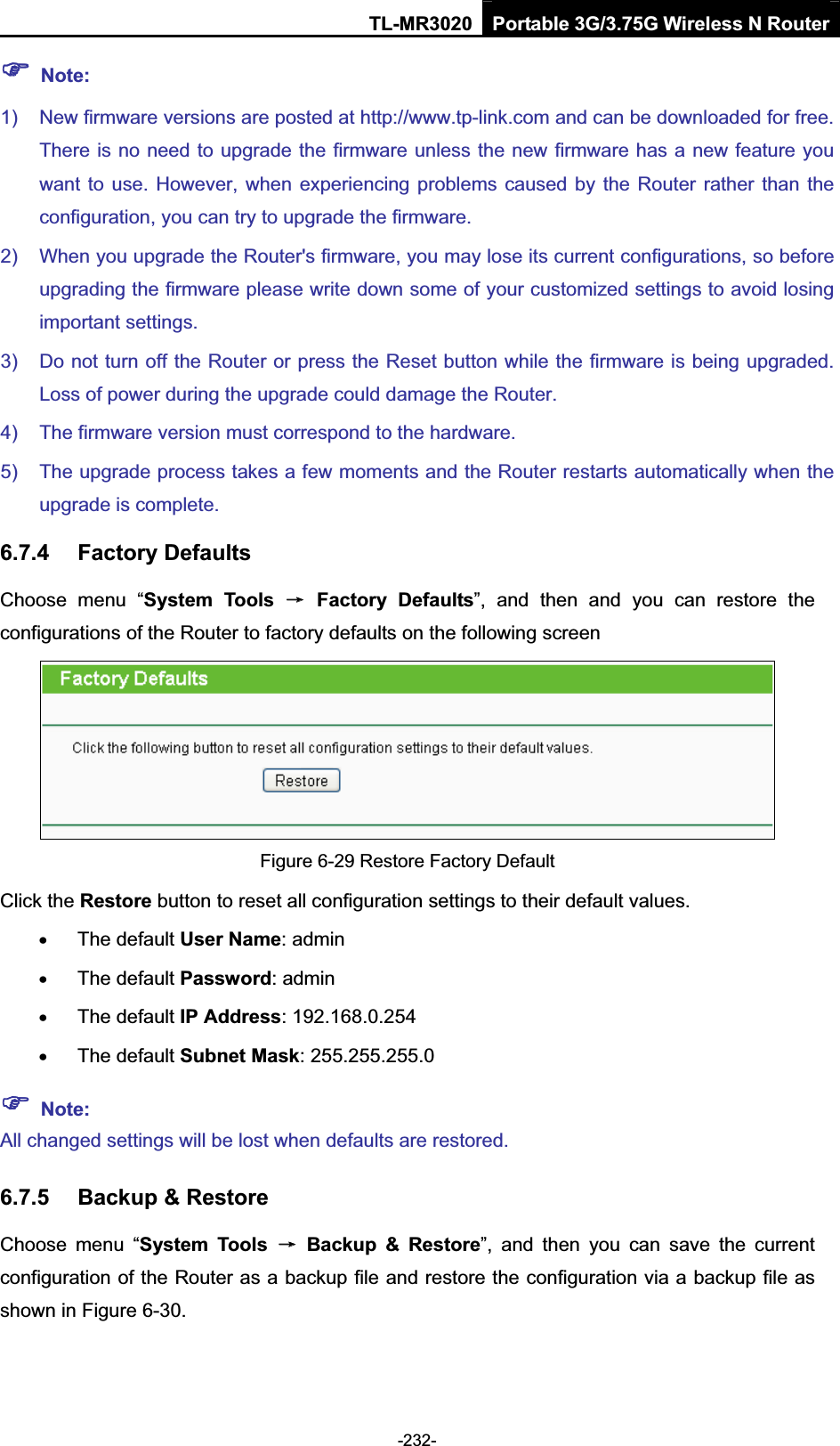
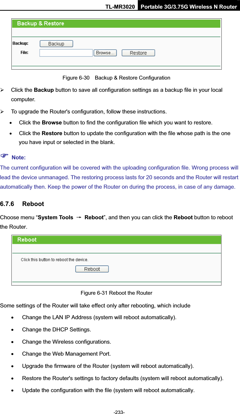

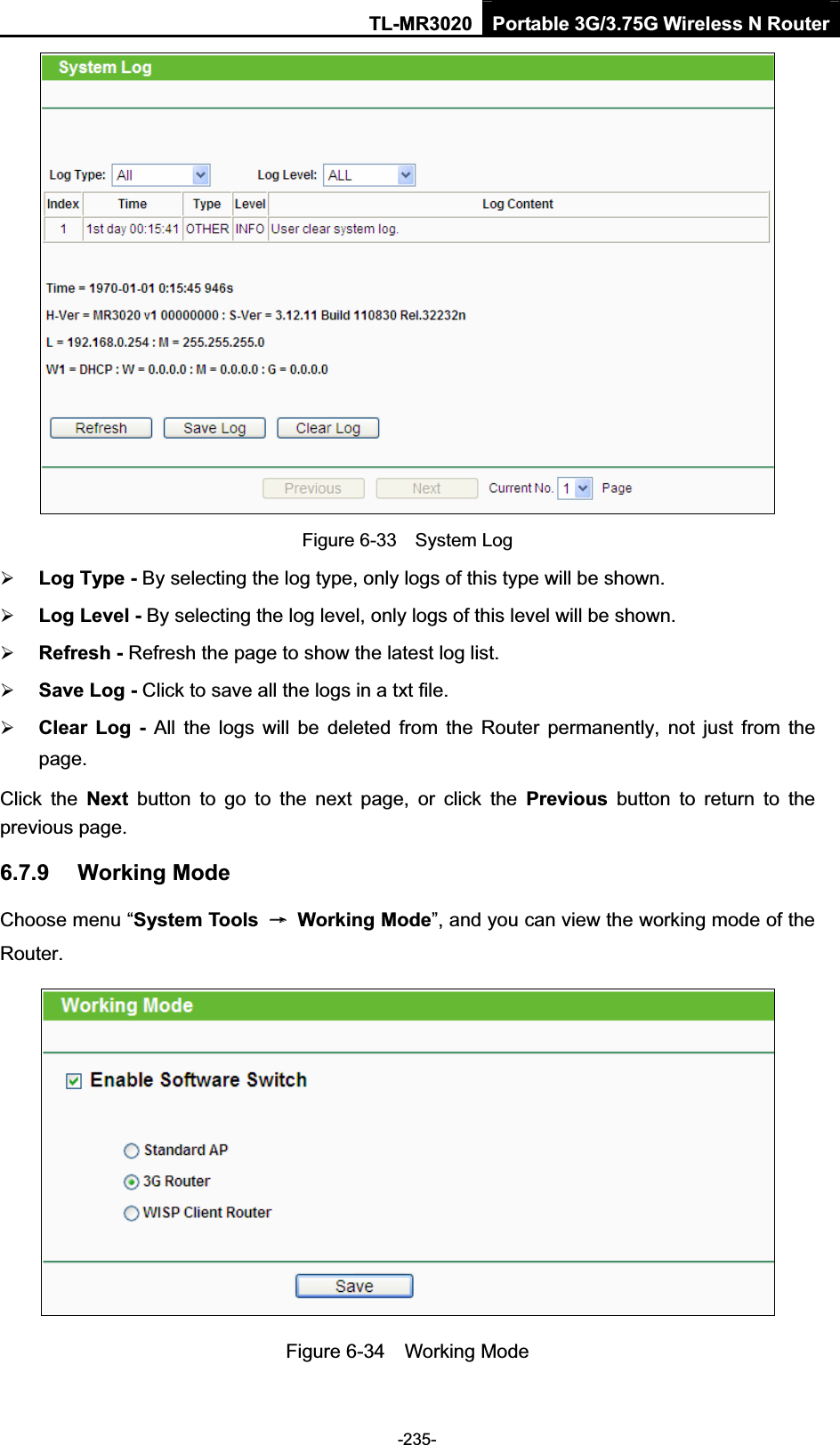
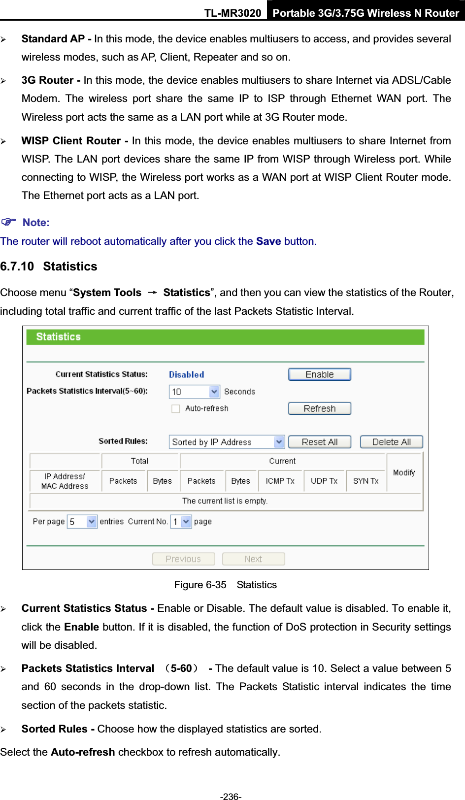
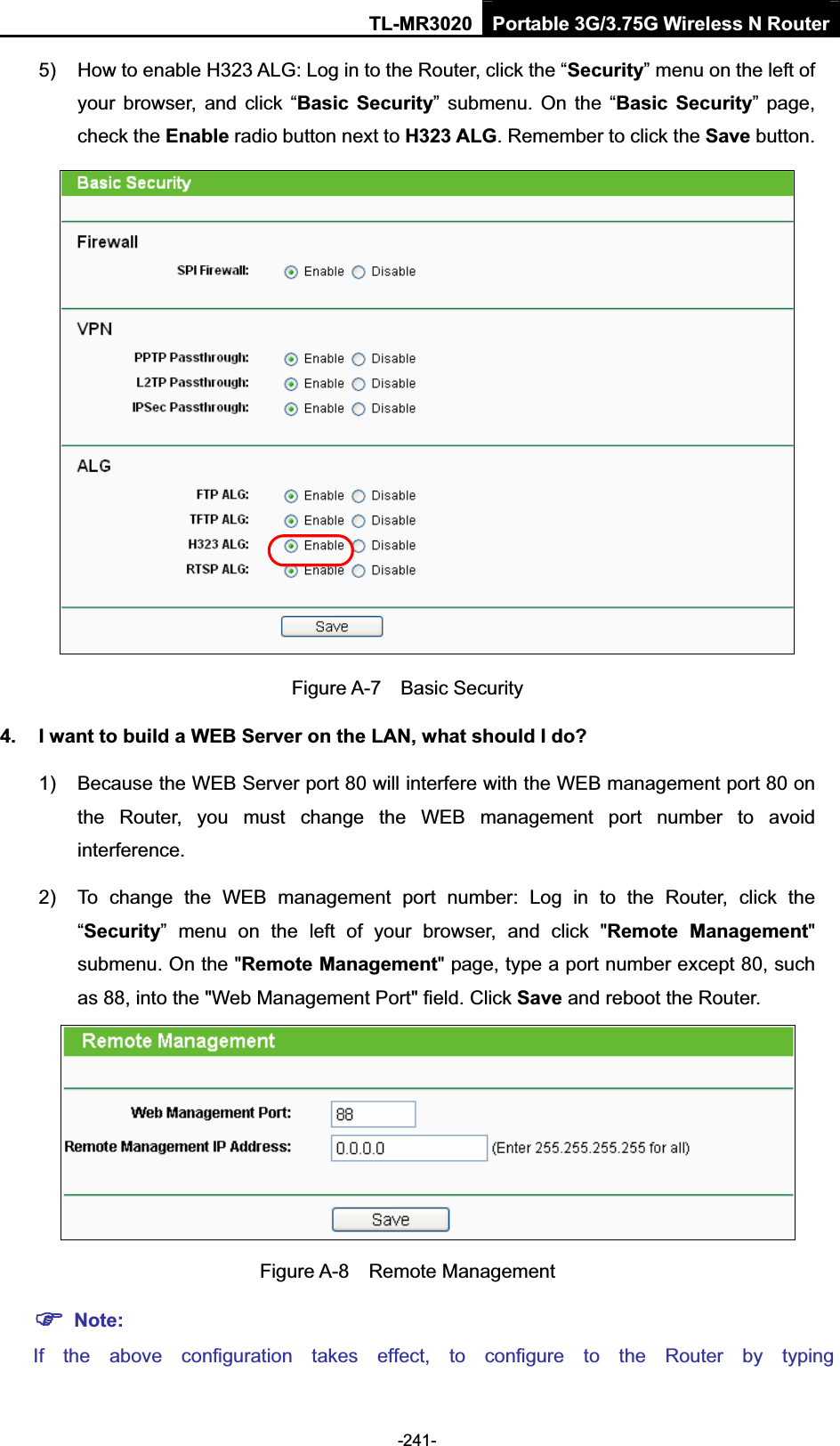
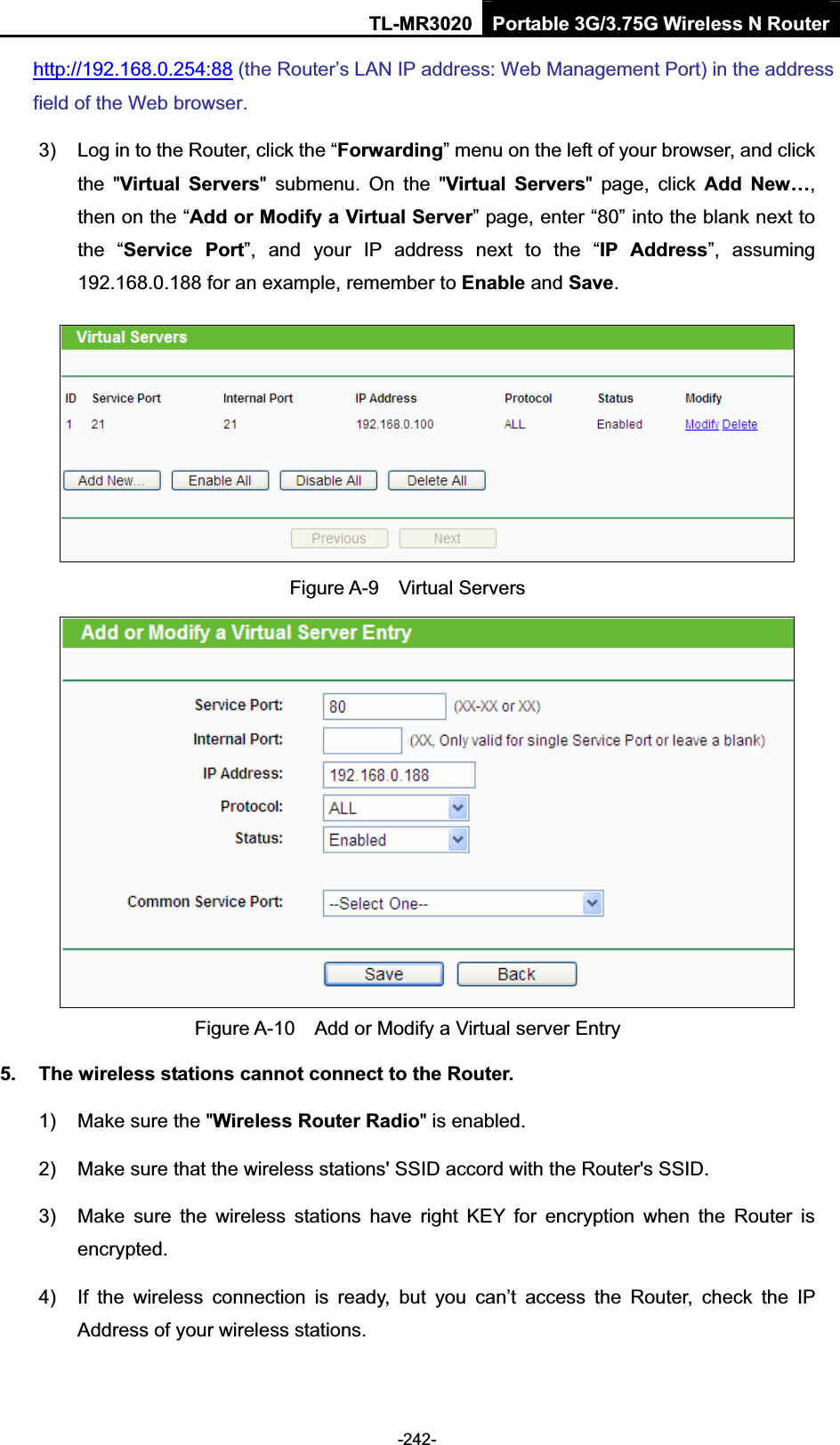
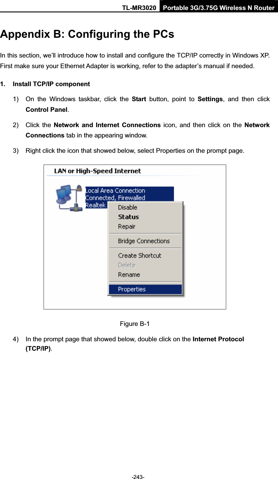
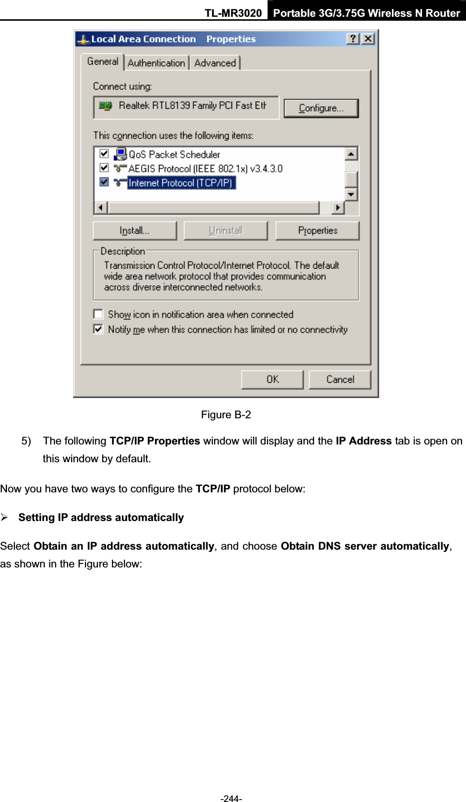
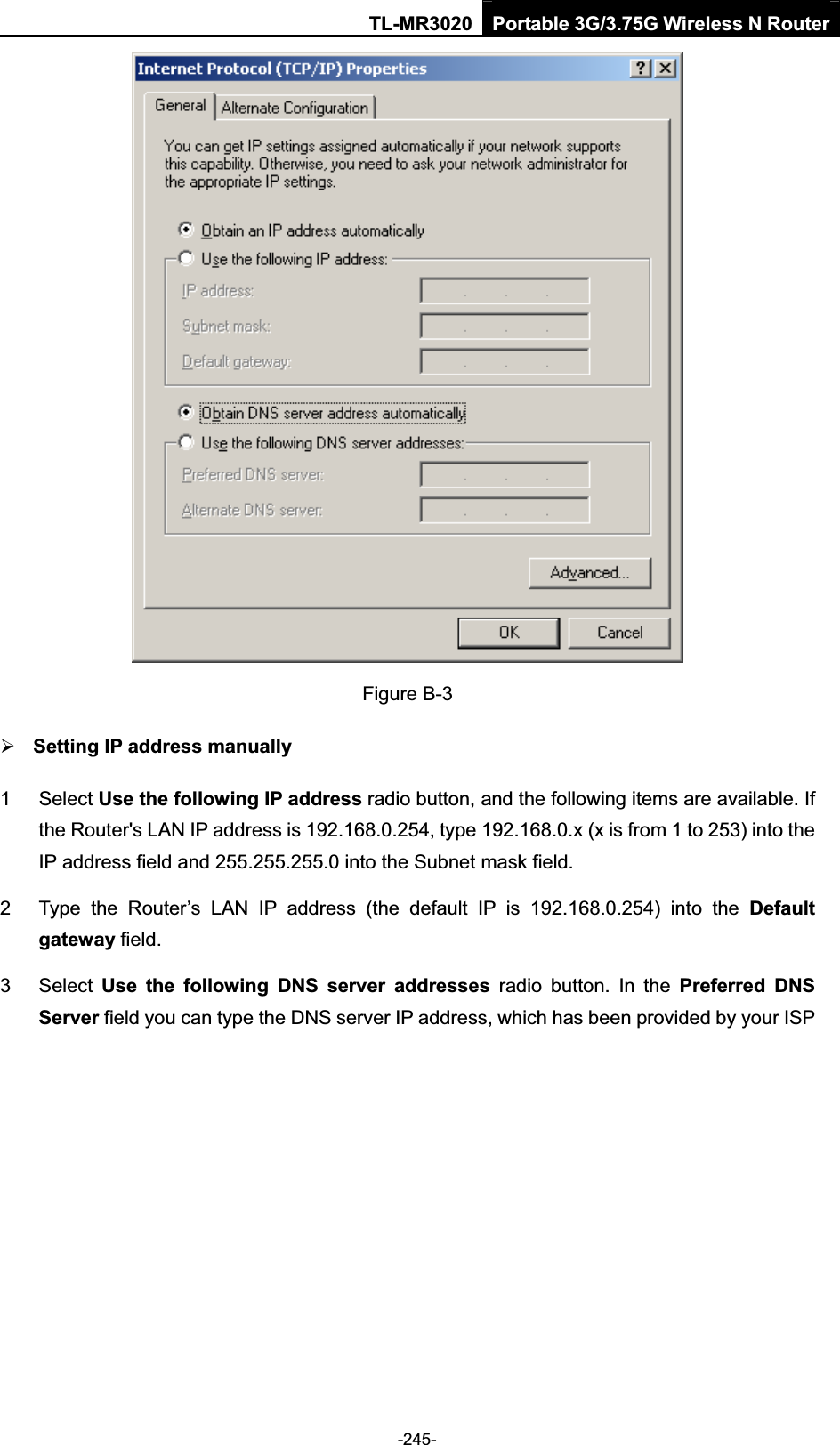
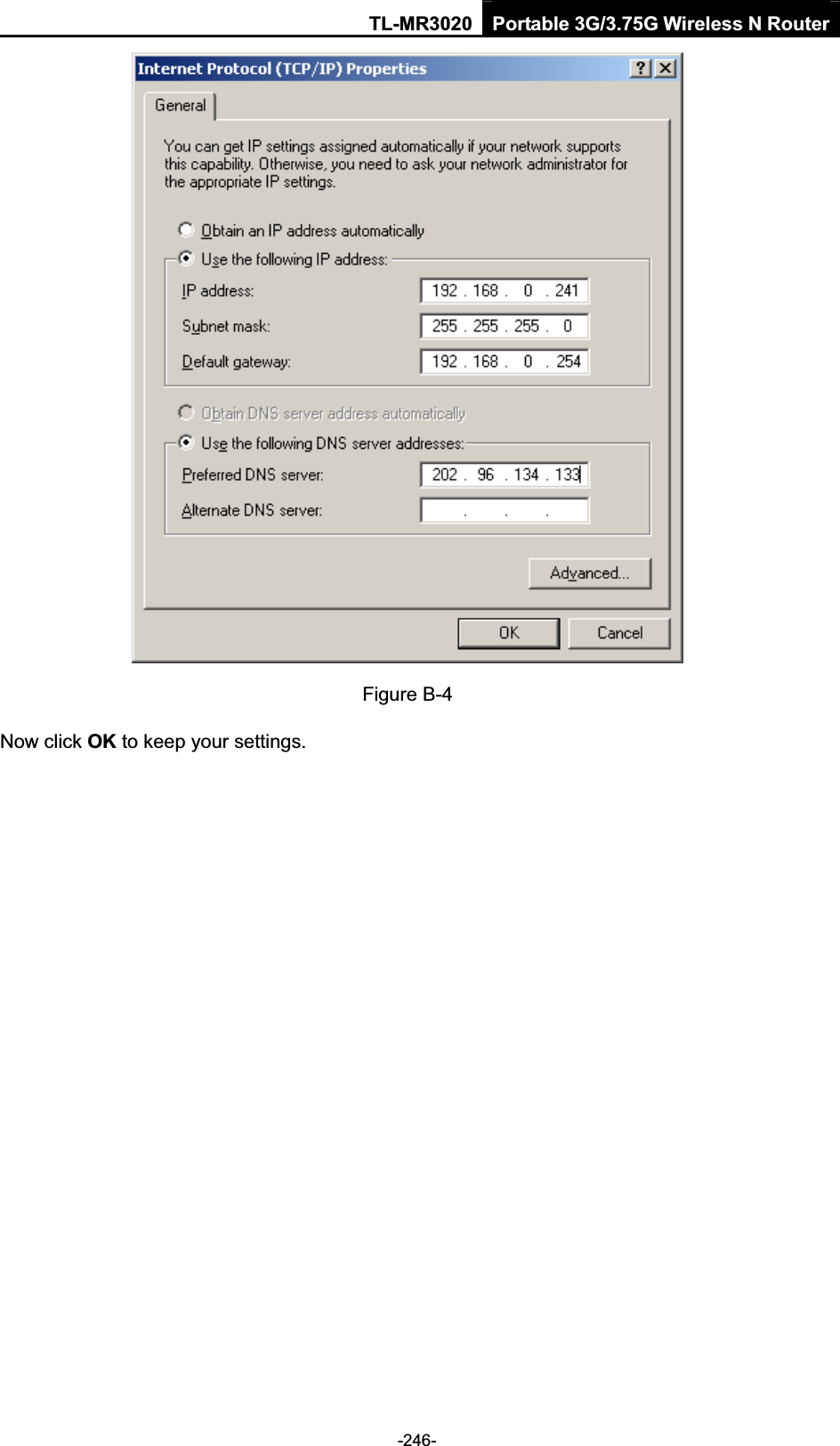
![TL-MR3020 Portable 3G/3.75G Wireless N Router-248-Appendix D: Glossary ¾802.11n - 802.11n builds upon previous 802.11 standards by adding MIMO (multiple-input multiple-output). MIMO uses multiple transmitter and receiver antennas to allow for increased data throughput via spatial multiplexing and increased range by exploiting the spatial diversity, perhaps through coding schemes like Alamouti coding. The Enhanced Wireless Consortium (EWC) [3] was formed to help accelerate the IEEE 802.11n development process and promote a technology specification for interoperability of next-generation wireless local area networking (WLAN) products. ¾802.11b - The 802.11b standard specifies a wireless networking at 11 Mbps using direct-sequence spread-spectrum (DSSS) technology and operating in the unlicensed radio spectrum at 2.4GHz, and WEP encryption for security. 802.11b networks are also referred to as Wi-Fi networks. ¾802.11g - specification for wireless networking at 54 Mbps using direct-sequence spread-spectrum (DSSS) technology, using OFDM modulation and operating in the unlicensed radio spectrum at 2.4GHz, and backward compatibility with IEEE 802.11b devices, and WEP encryption for security. ¾DDNS (Dynamic Domain Name System) - The capability of assigning a fixed host and domain name to a dynamic Internet IP Address. ¾DHCP (Dynamic Host Configuration Protocol) - A protocol that automatically configure the TCP/IP parameters for the all the PC(s) that are connected to a DHCP server. ¾DMZ (Demilitarized Zone) - A Demilitarized Zone allows one local host to be exposed to the Internet for a special-purpose service such as Internet gaming or videoconferencing. ¾DNS (Domain Name System) - An Internet Service that translates the names of websites into IP addresses. ¾Domain Name - A descriptive name for an address or group of addresses on the Internet. ¾DSL (Digital Subscriber Line) - A technology that allows data to be sent or received over existing traditional phone lines. ¾ISP (Internet Service Provider) - A company that provides access to the Internet. ¾MTU (Maximum Transmission Unit)- The size in bytes of the largest packet that can be transmitted.¾NAT (Network Address Translation) - NAT technology translates IP addresses of a local area network to a different IP address for the Internet. ¾PPPoE (Point to Point Protocol over Ethernet) - PPPoE is a protocol for connecting remote hosts to the Internet over an always-on connection by simulating a dial-up connection. ¾SSID - AService Set Identification is a thirty-two character (maximum) alphanumeric key](https://usermanual.wiki/TP-Link-Technologies/MR3020/User-Guide-1639840-Page-257.png)