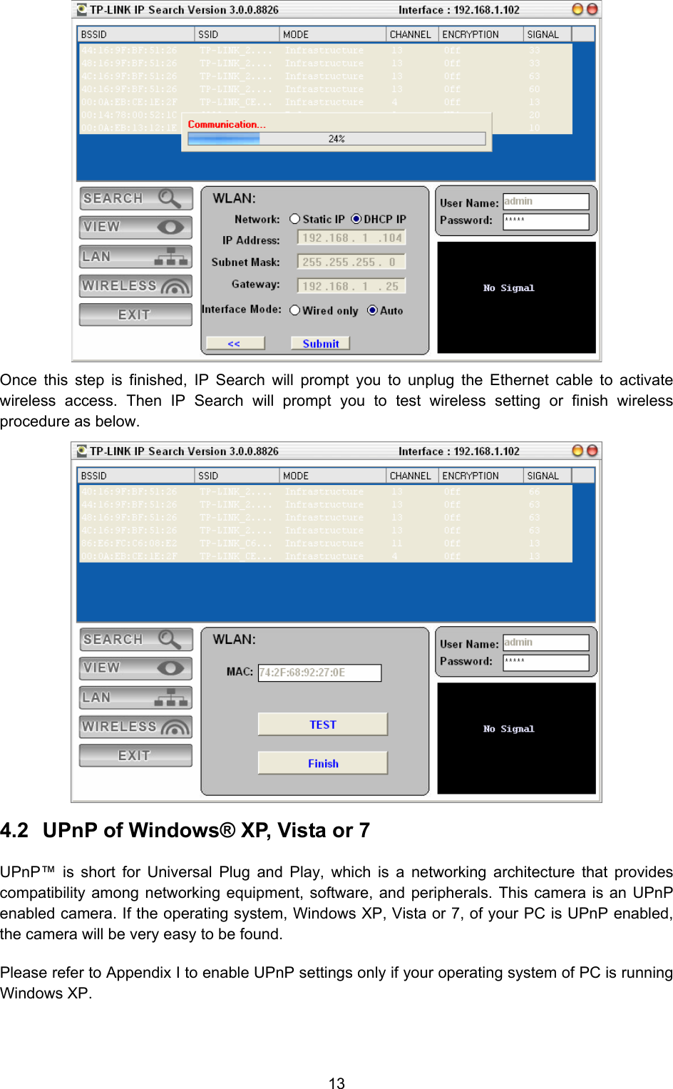
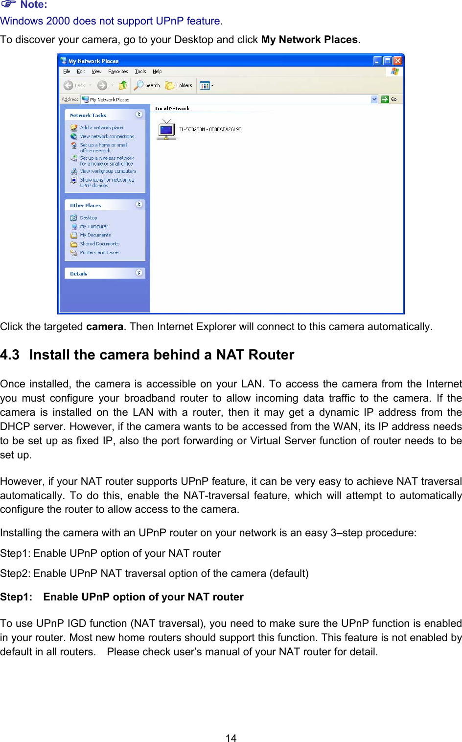
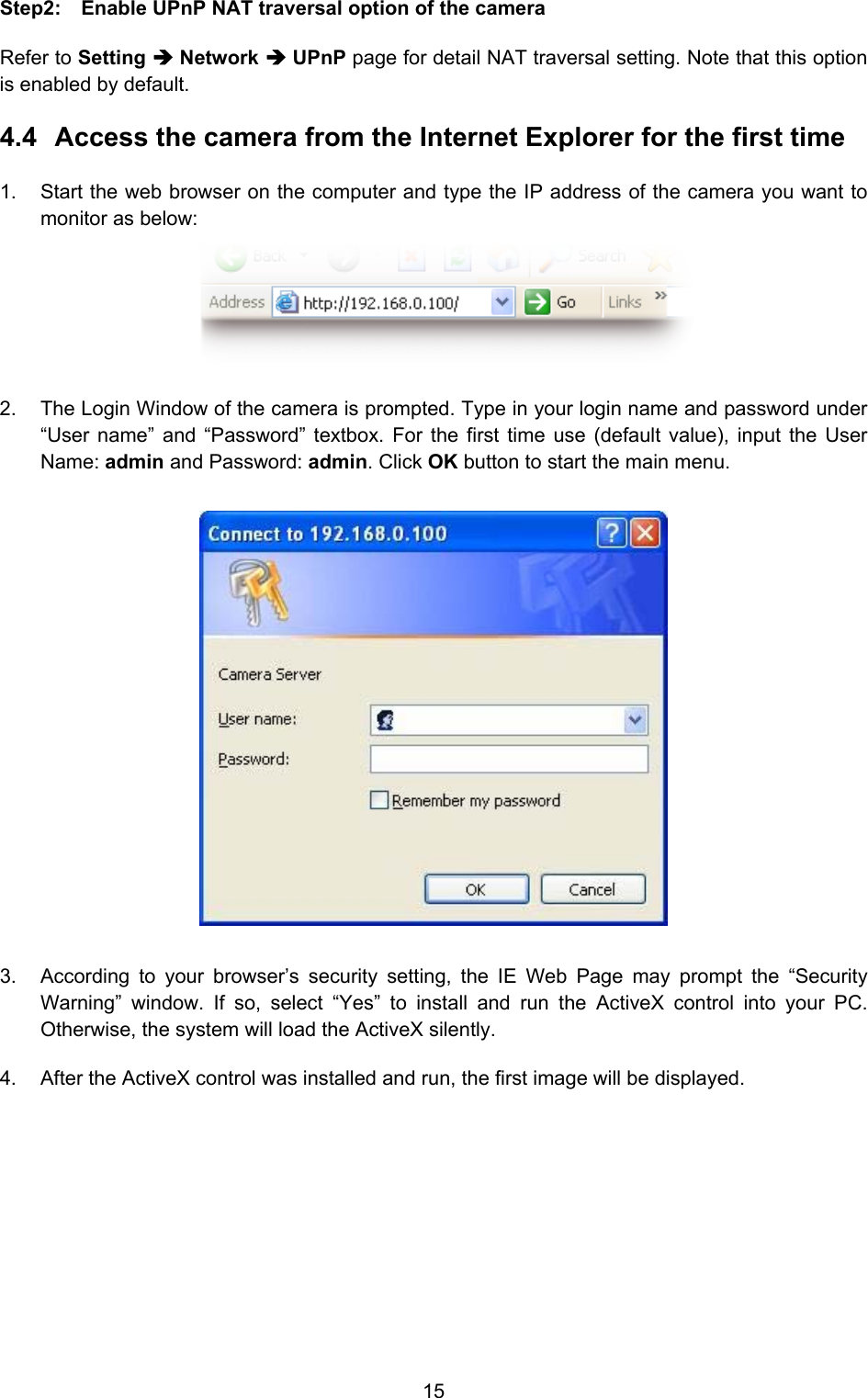
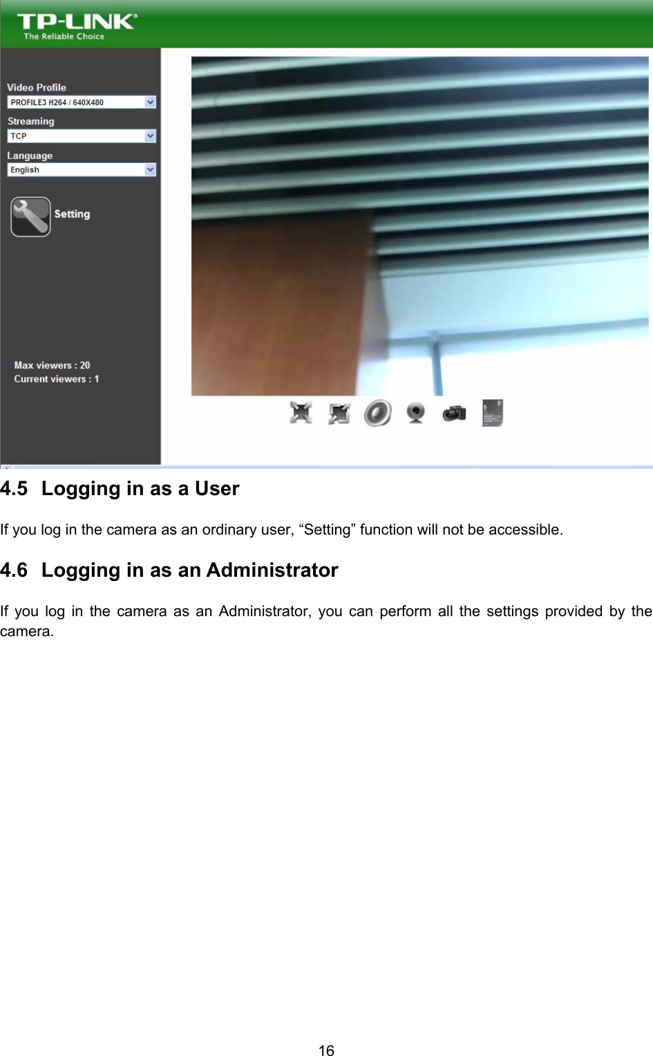
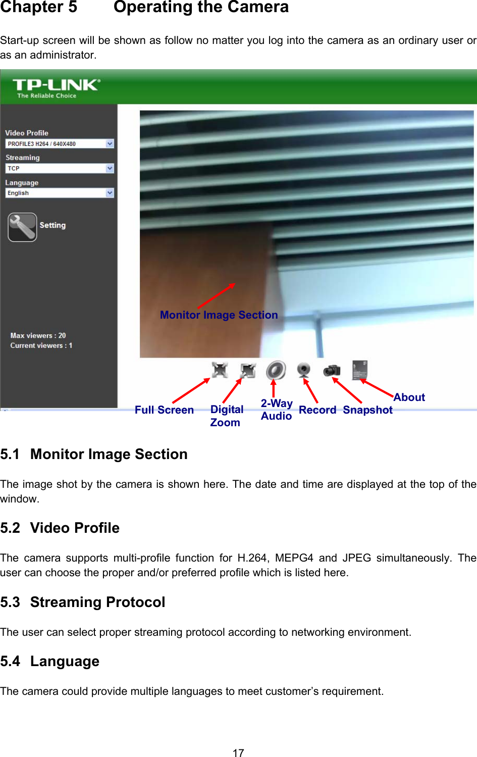
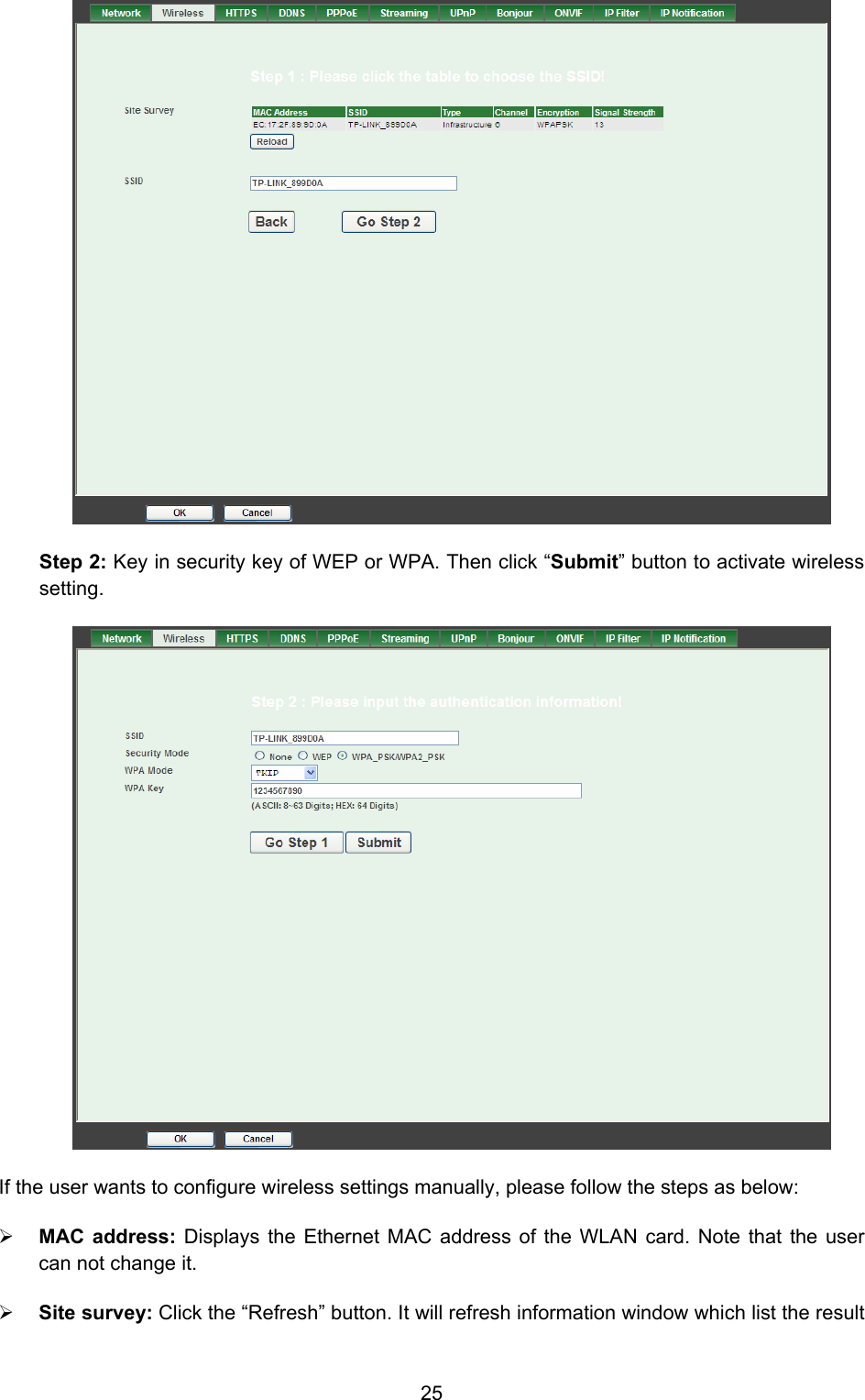
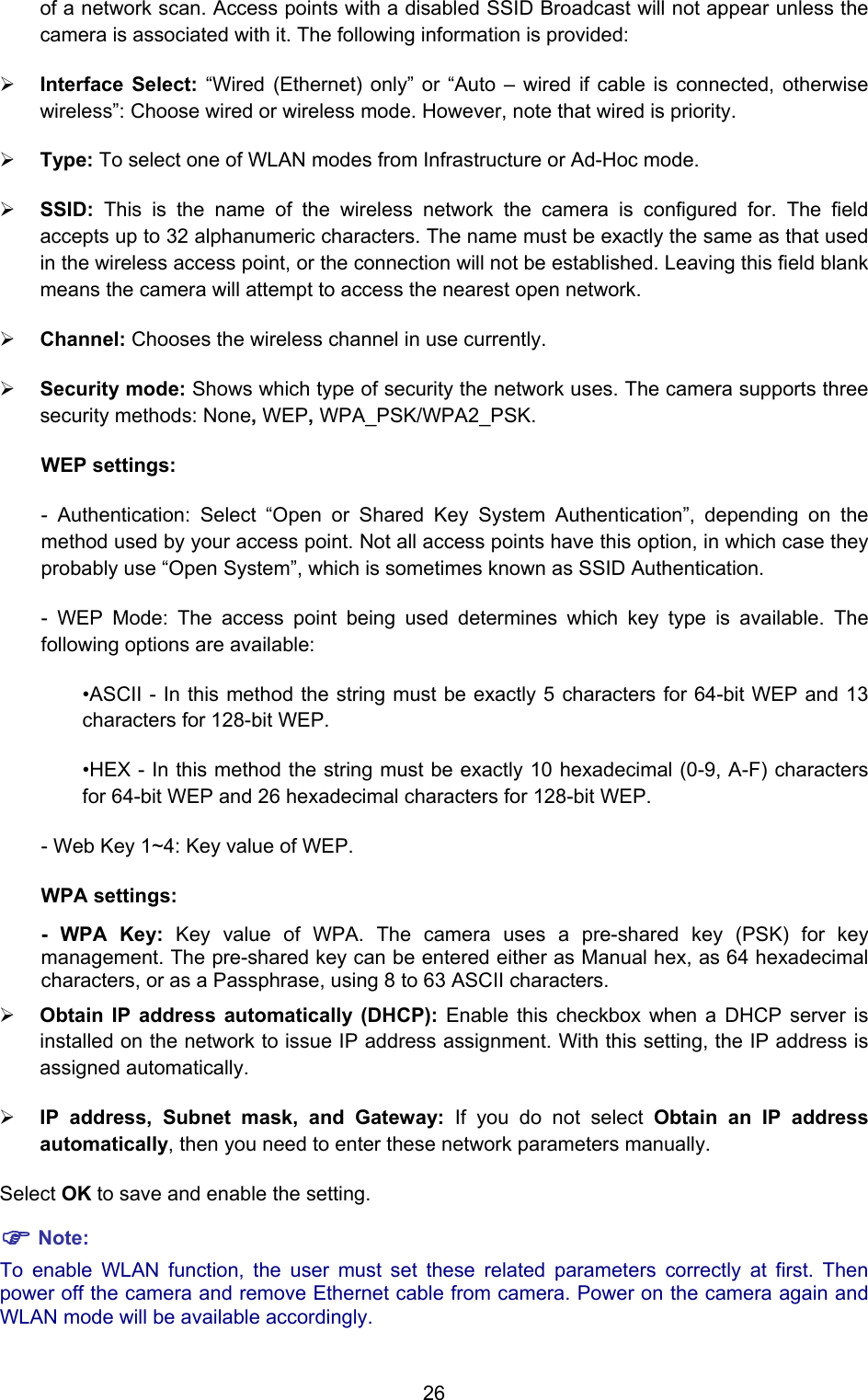
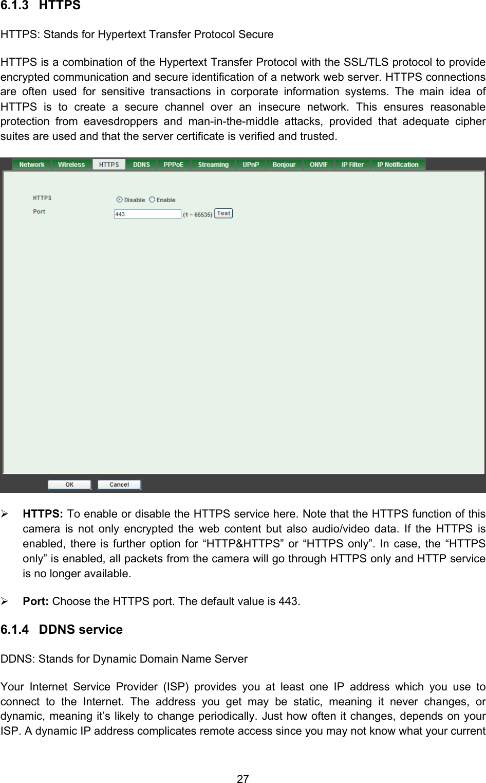
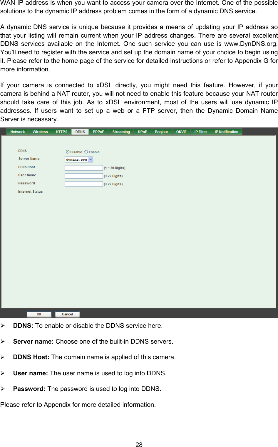
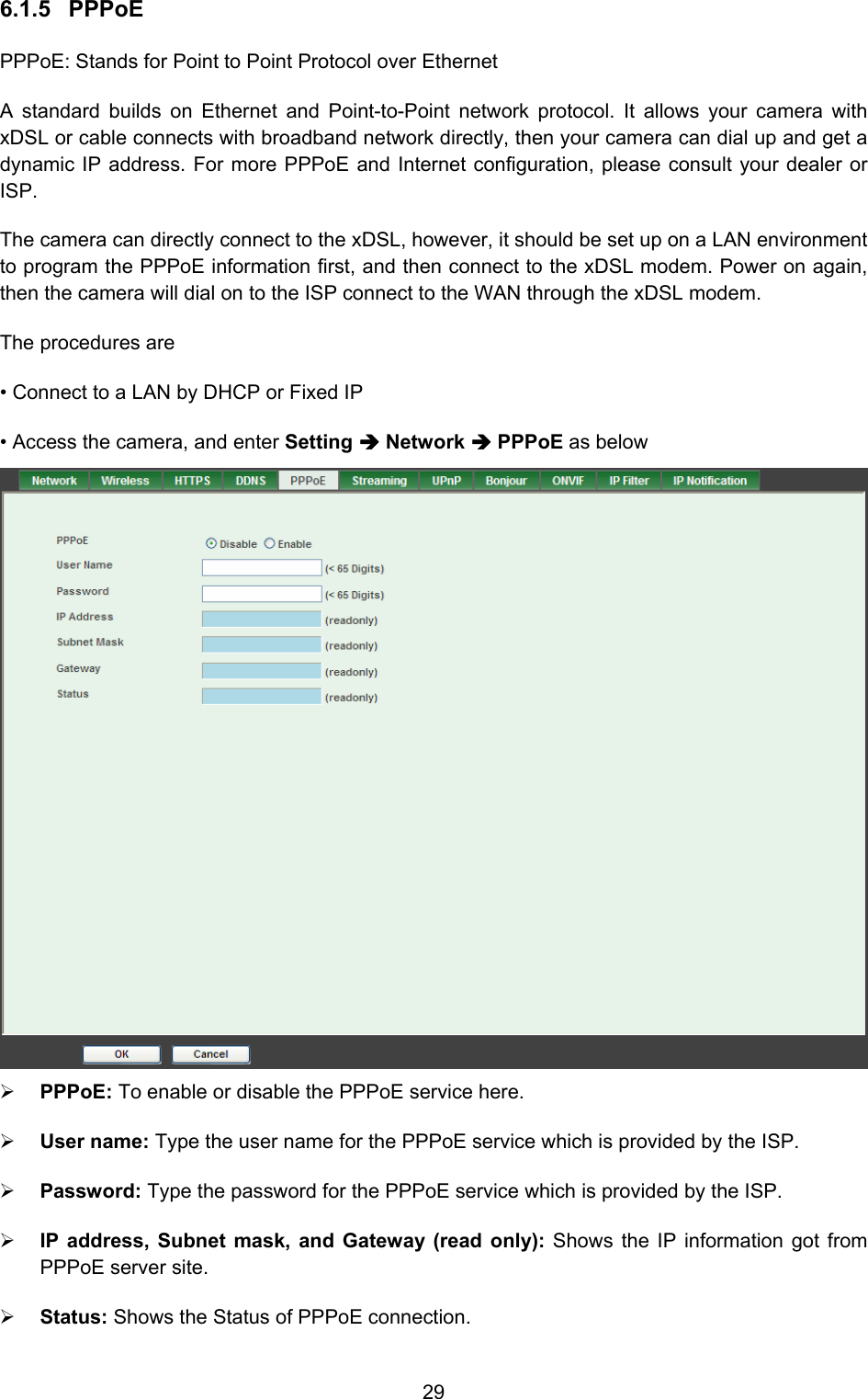
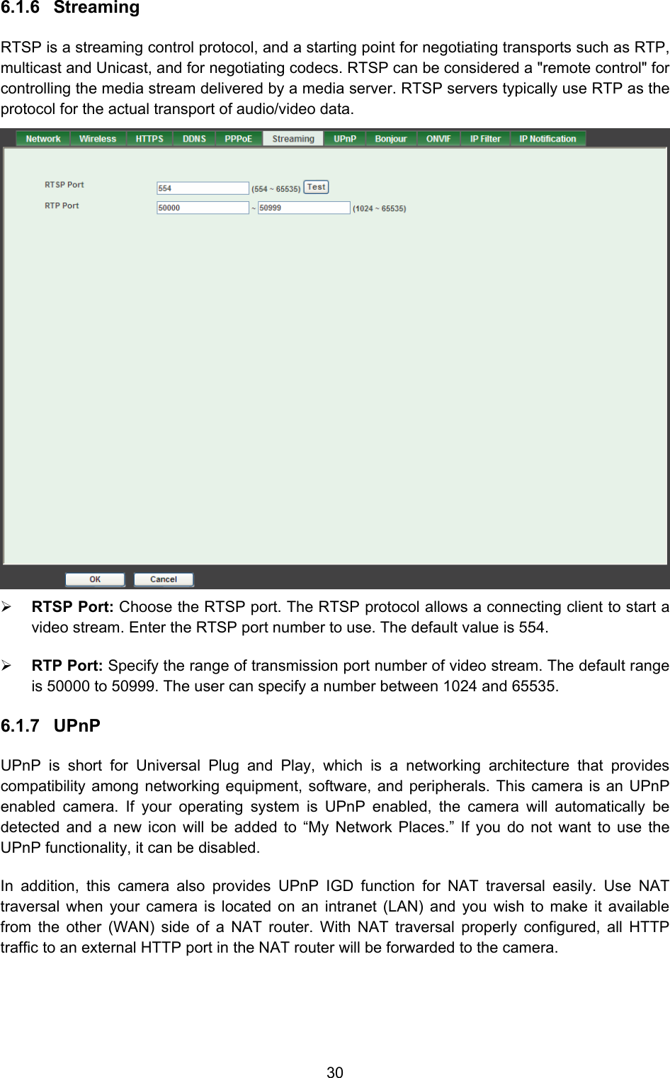
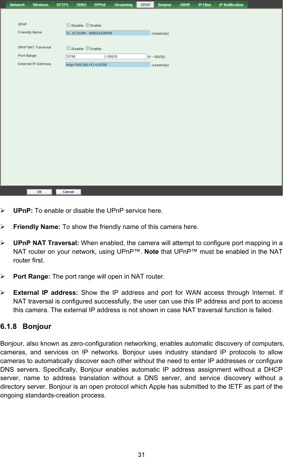
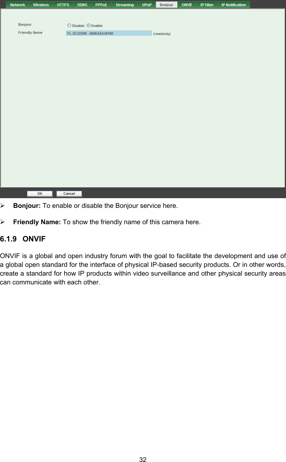
TP Link Technologies SC3230N Wireless N Megapixel Surveillance Camera User Manual
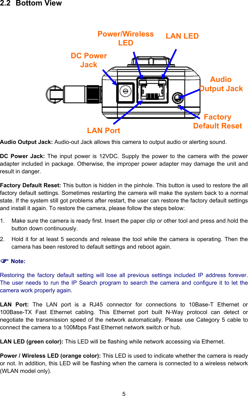
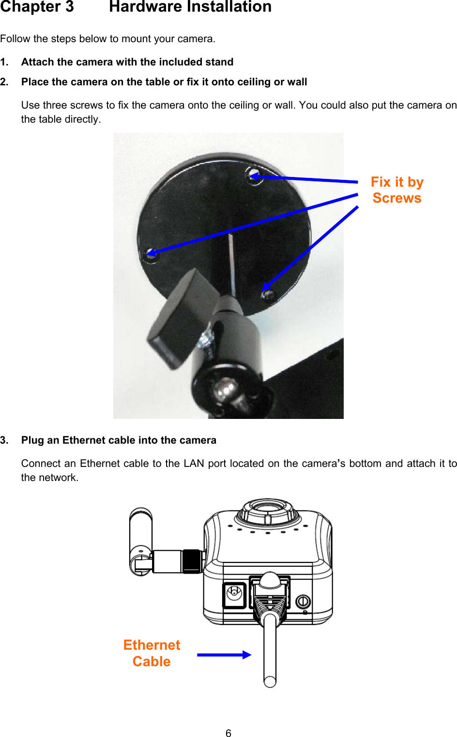
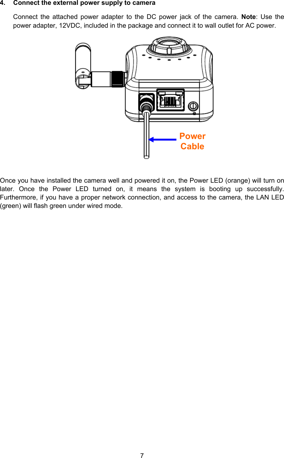
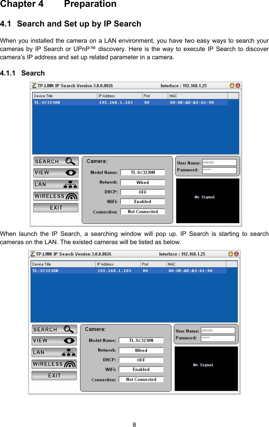
TP-Link Technologies Co., Ltd. Wireless N Megapixel Surveillance Camera
UserManual.wiki
>
TP Link Technologies
>
SC3230N User Manual
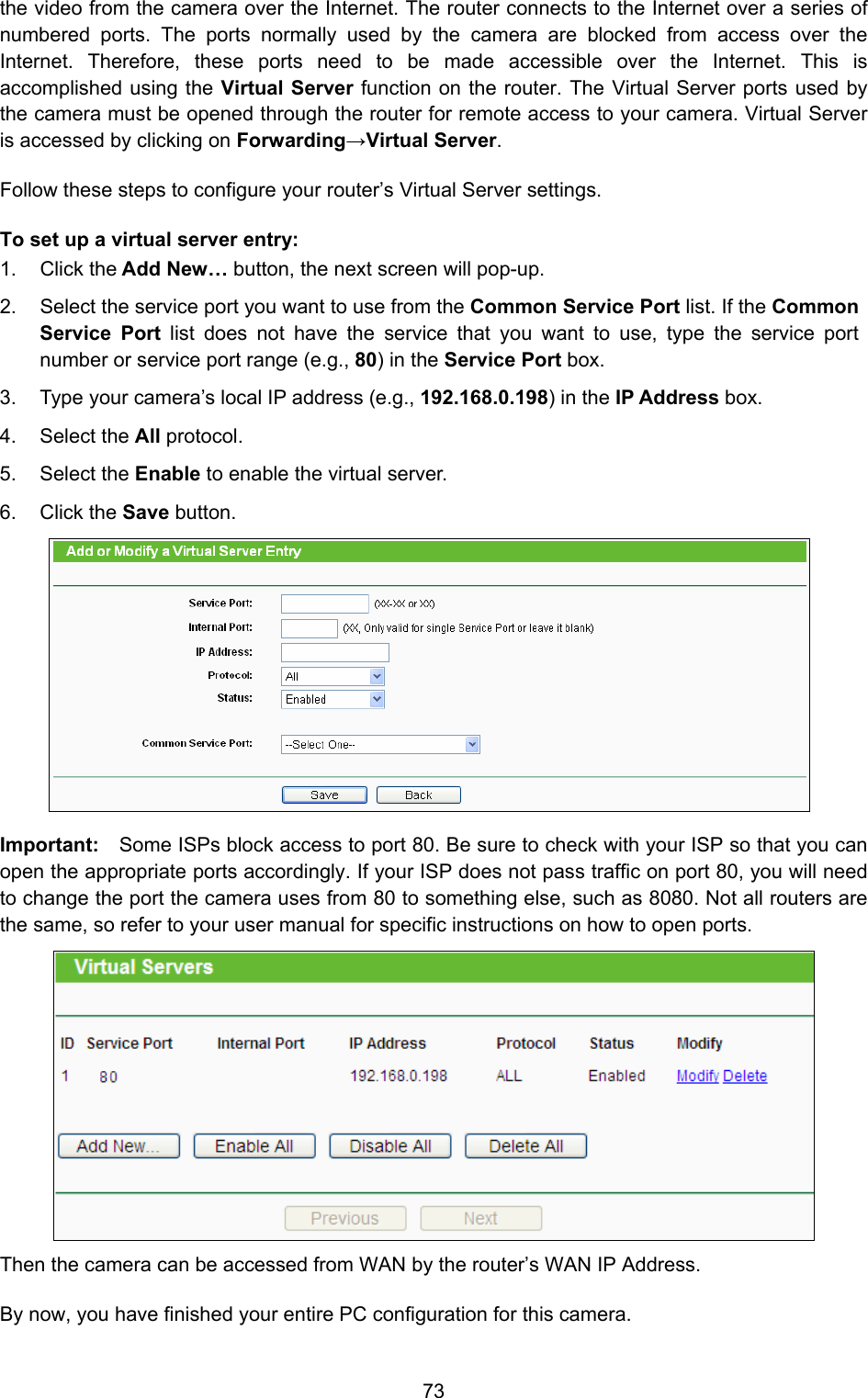
User Manual
Navigation menu
Upload a User Manual
Namespaces
Wiki Guide
HTML
PDF
Info
Views
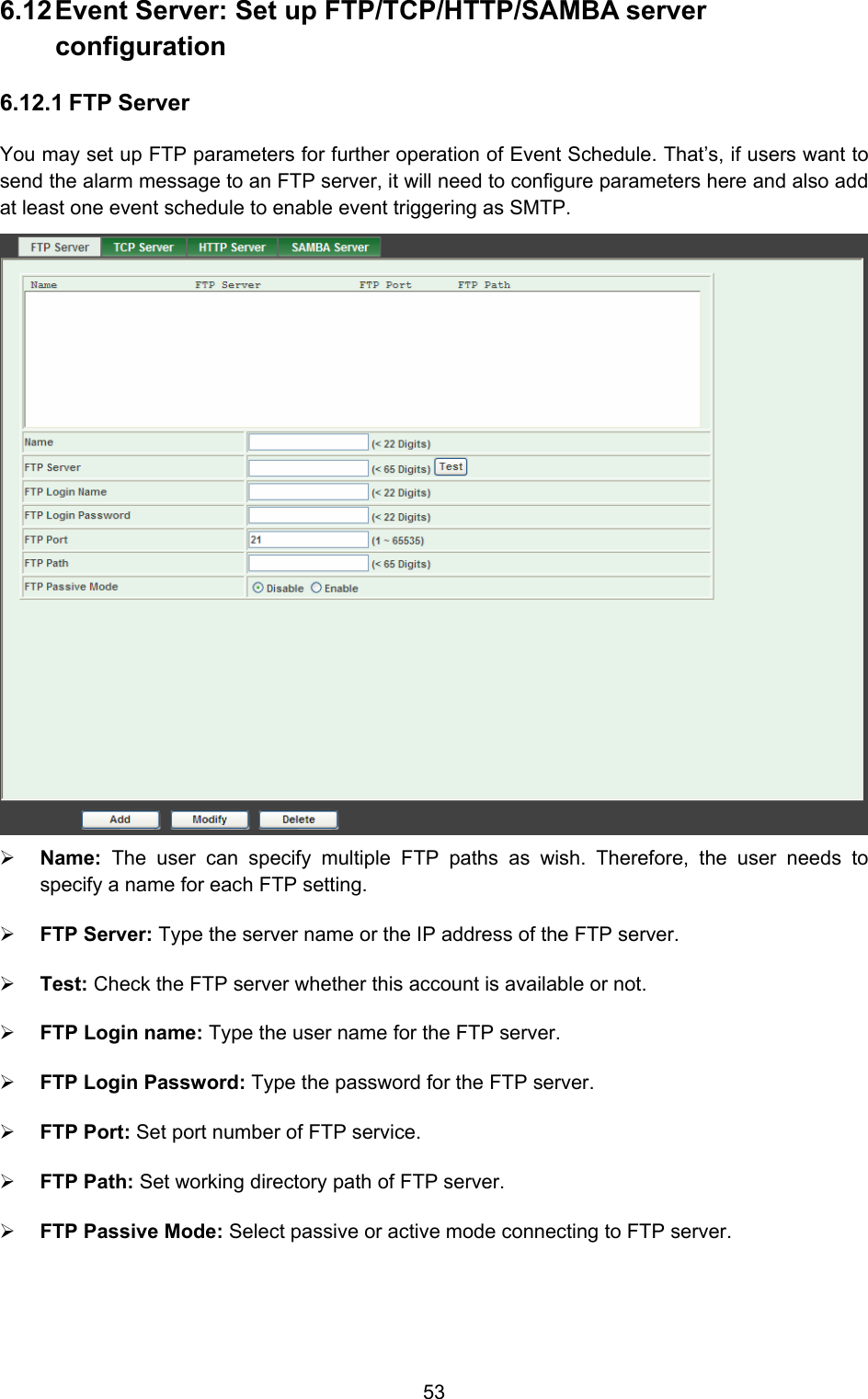
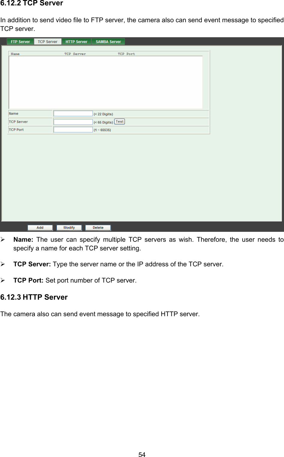
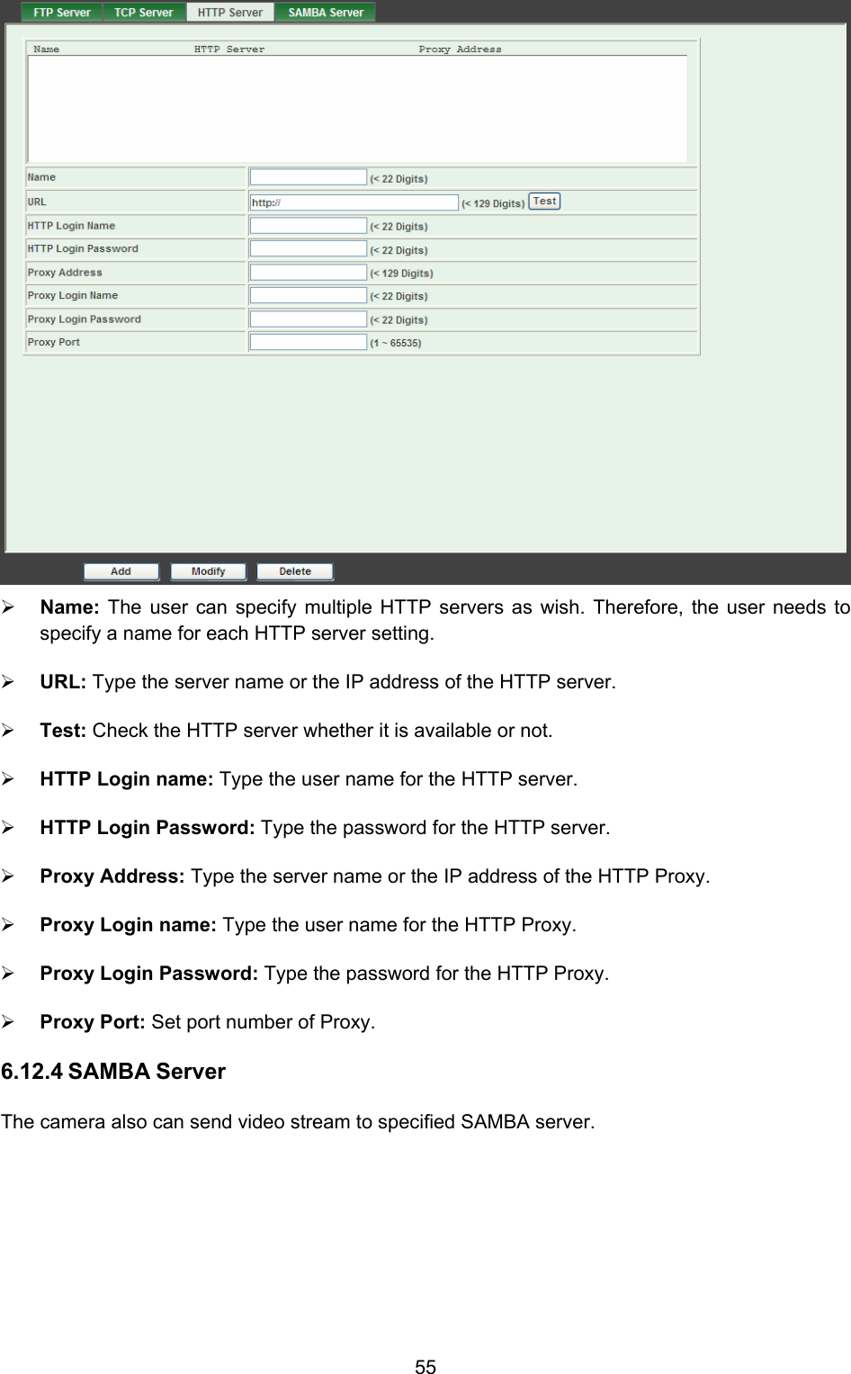
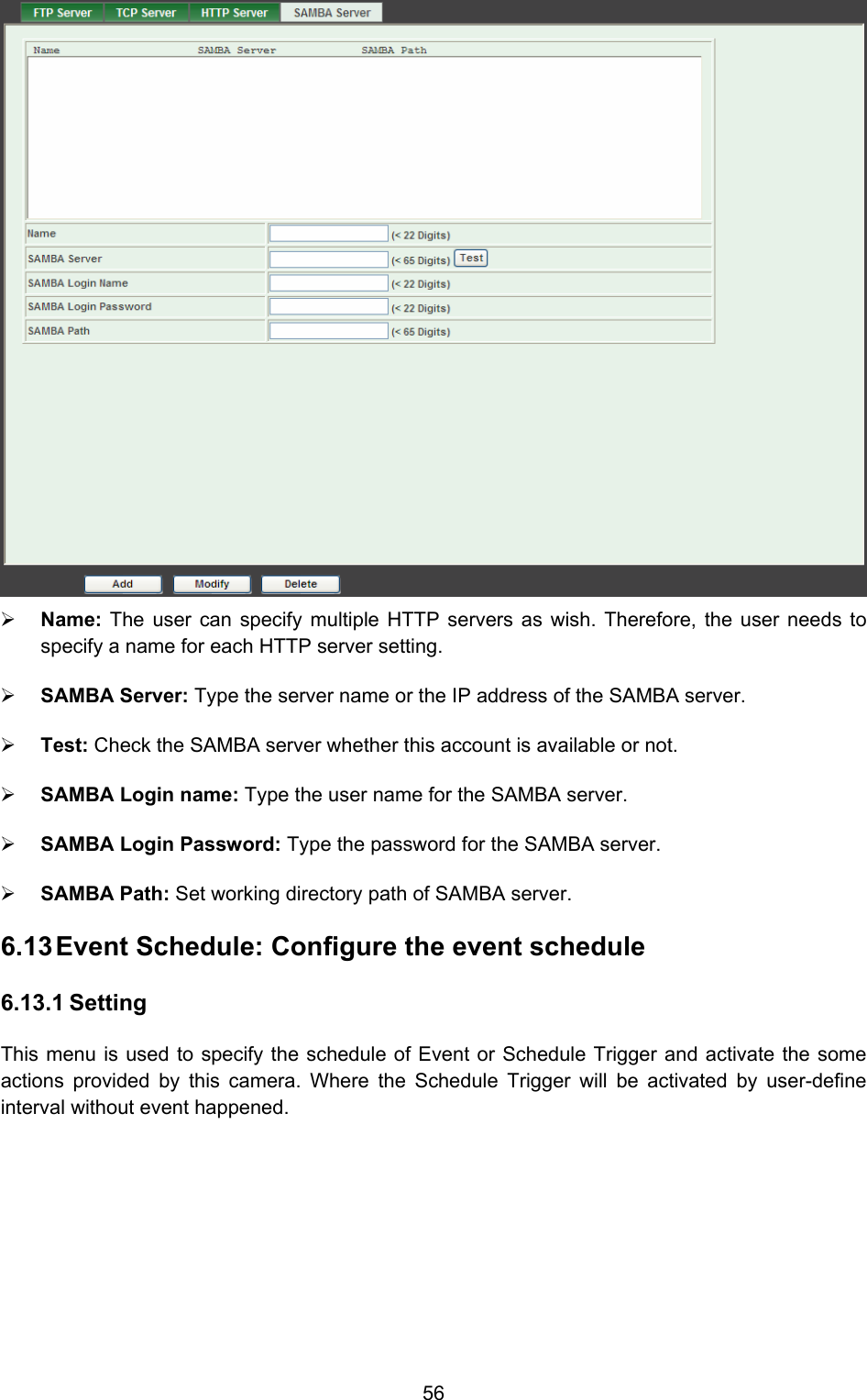
User Manual
Discussion / Help
Navigation