TP Link Technologies SC3430N Wireless N H.264 Megapixel Surveillance Camera User Manual TL SC3430N User Guide
TP-Link Technologies Co., Ltd. Wireless N H.264 Megapixel Surveillance Camera TL SC3430N User Guide
Contents
- 1. User Manual 1
- 2. User Manual 2
- 3. User Manual 3
User Manual 1
TL-SC3430N
Wireless N H.264 Megapixel Surveillance Camera
Rev: 1.0.0
1910010550

COPYRIGHT & TRADEMARKS
Specifications are subject to change without notice. is a registered trademark of
TP-LINK TECHNOLOGIES CO., LTD. Other brands and product names are trademarks or
registered trademarks of their respective holders.
No part of the specifications may be reproduced in any form or by any means or used to make any
derivative such as translation, transformation, or adaptation without permission from TP-LINK
TECHNOLOGIES CO., LTD. Copyright © 2012 TP-LINK TECHNOLOGIES CO., LTD.
All rights reserved.
http://www.tp-link.com

FCC STATEMENT
This equipment has been tested and found to comply with the limits for a Class B digital device,
pursuant to part 15 of the FCC Rules. These limits are designed to pro-vide reasonable protection
against harmful interference in a residential installation. This equipment generates, uses and can
radiate radio frequency energy and, if not in-stalled and used in accordance with the instructions,
may cause harmful interference to radio communications. However, there is no guarantee that
interference will not occur in a particular installation. If this equipment does cause harmful
interference to radio or television reception, which can be determined by turning the equipment off
and on, the user is encouraged to try to correct the interference by one or more of the following
measures:
Reorient or relocate the receiving antenna.
Increase the separation between the equipment and receiver.
Connect the equipment into an outlet on a circuit different from that to which the receiver is
connected.
Consult the dealer or an experienced radio/ TV technician for help.
This device complies with part 15 of the FCC Rules. Operation is subject to the following two
conditions:
This device may not cause harmful interference.
This device must accept any interference received, including interference that may cause
undesired operation.
Any changes or modifications not expressly approved by the party responsible for compliance
could void the user’s authority to operate the equipment.
CE Mark Warning
This is a class B product. In a domestic environment, this product may cause radio interference, in
which case the user may be required to take adequate measures.
i
CONTENTS
CONTENTS ..........................................................................................................................i
Package Contents..............................................................................................................1
Chapter 1 Safety Instructions..........................................................................................2
Chapter 2 Minimum System Requirement & Product Feature......................................3
2.1 System Requirement ........................................................................................................ 3
2.2 Product Features .............................................................................................................. 3
2.3 Physical Overview ............................................................................................................ 4
2.4 Mount the Camera ............................................................................................................ 6
2.5 Hardware Connection ....................................................................................................... 7
Chapter 3 Using IP Camera via Web Browser................................................................9
3.1 Obtain the IP Address ....................................................................................................... 9
3.2 Windows Web Browser....................................................................................................11
3.3 Mac Web Browser .......................................................................................................... 12
Chapter 4 Operating IP Camera via Mobile Phone ......................................................15
4.1 Mobile Phone Viewing .................................................................................................... 15
4.2 Using IP Camera via iPhone........................................................................................... 15
Chapter 5 Configuration of Main Menu ........................................................................17
5.1 Live View ........................................................................................................................ 17
5.2 Setting............................................................................................................................. 18
5.3 Client Setting ..................................................................................................................19
5.4 Image Setup ................................................................................................................... 20
Chapter 6 Setting-Basic.................................................................................................21
6.1 System............................................................................................................................ 21
6.2 Camera ........................................................................................................................... 24
6.3 Network........................................................................................................................... 33
6.4 Security........................................................................................................................... 48
Chapter 7 Setting-Advanced .........................................................................................51
7.1 FTP Client....................................................................................................................... 51
7.2 SMTP.............................................................................................................................. 55
7.3 Network Storage ............................................................................................................. 59
7.4 Memory Card .................................................................................................................. 64
7.5 HTTP event..................................................................................................................... 69
7.6 Schedule......................................................................................................................... 74
7.7 Alarm Buffer....................................................................................................................75
7.8 Motion Detection............................................................................................................. 76
7.9 Audio Detection .............................................................................................................. 76
7.10 System Log ............................................................................................................. 77
Appendix….......................................................................................................................79
A. Frame-rate and Bitrate Table – Help to set IP Camera with your network environment to
access Internet. ..................................................................................................................... 79
B. Storage Requirement Table - Help to set Recording Storage System............................... 84
ii
C. System Requirement – Help to setup System .................................................................. 87
Europe – EU Declaration of Conformity.........................................................................89
Federal Communication Commission Interference Statement ....................................92
1
Package Contents
The following items should be found in your package:
¾ TL-SC3430N Wireless N H.264 Megapixel Surveillance Camera
¾ Power Adapter
¾ Mounting Bracket with three screws, a Lock Ring, a Brace and a Base Plate
¾ RJ45 Cable
¾ Quick Installation Guide
¾ Resource CD, including:
z This User Guide
z Application Guide
z Other helpful information
)
Note:
Make sure that the package contains the above items. If any of the listed items is damaged or missing,
please contact your distributor.
2
Chapter 1 Safety Instructions
¾ Before you use this product
This product has been designed with safety in mind. However, the electrical products can cause fires
which may lead to serious body injury if not used properly. To avoid such accidents, be sure to heed the
following.
¾ Legal Caution
Video and audio surveillance can be forbidden by laws that vary from country to country. Check the laws
in your local region before using this product for surveillance purposes.
¾ Don't open the housing of the product
Don't try to open the housing or remove the covers, for it may expose you to dangerous voltage or other
hazards.
¾ Don't use the accessories not recommend by the manufacturer
¾ Heed the safety precautions
Be sure to follow the general safety precautions and the “Operation Notice.”
¾ Operation Notice - Operating or storage location
Avoid operating or storing the Camera in the following locations:
x Extremely hot or cold places
(Operating temperature: 0 °C to + 40 °C [32 °F to 104°F] )
x Exposed to direct sunlight for a long time, or close to heating equipment (e.g., near heaters)
x Close to water (e.g.,near a bathtub, kitchen sink, laundry tub)
x Close to sources of strong magnetism
x Close to sources of powerful electromagnetic radiation, such as radios or TV transmitters
x Locations subject to strong vibration or shock
¾ In case of a breakdown
In case of system breakdown, discontinue use and contact your authorized dealer.
¾ In case of abnormal operation
x If the unit emits smoke or an unusual smell,
x If water or other foreign objects enter the cabinet, or
x If you drop the unit or damage the cabinet: 1. Disconnect the cable and the connecting cables.
2. Contact your authorized dealer or the store where you purchased the product.
¾ Transportation
When transporting the camera, repack it as originally packed at the factory or in materials of equal
quality.
¾ Ventilation
To prevent heat buildup, do not block air circulation around the device.
¾ Cleaning
x Use a soft, dry cloth to clean the external surfaces of the device. Stubborn stains can be
removed using a soft cloth dampened with a small quantity of detergent solution, then wipe
dry.
x Do not use volatile solvents such as alcohol, benzene or thinners as they may damage the
surface.

3
Chapter 2 Minimum System Requirement & Product Feature
2.1 System Requirement
For normal operation and viewing of the network camera, it’s recommended that your system meets
these minimum requirements for proper operation:
Item Requirements
CPU Pentium 4 2.8GHz (or equivalent AMD)
Graphic Card 256 MB RAM graphic cards(or equivalent on-board graphic cards)
RAM 1G
Operating
System
Windows 2000 / Windows 2003 / Windows XP / Windows Vista /
Windows 7
Web Browser Internet Explore 6 or higher
)
Note:
Please keep updating the latest Windows software and service package. (Ex: Net Framework, Windows
Media Player, Enhance ActiveX Security)
2.2 Product Features
These easy-to-follow instructions make it quick and simple for setup and operation, so you’ll also soon
be enjoying the benefits of these product features:
SYSTEM
Resolutions
H.264 / MPEG-4 / Motion JPEG:
4 resolutions from 1280 x 1024 to 320 x 240 via API and configuration web
page
3GPP: 2 resolutions from 320 x 240 to 160 x120 via compatible cellphone.
Screen Resolution Higher than 1024 * 720 pixels
Compressing format H.264 / MPEG-4 / Motion JPEG
Frame Rate Up to 15 fps at 1280 x 1024
Up to 30 fps at 640 x 480
Rotation: Mirror, Flip, Mirror Flip
Brightness / Contrast / Saturation / Sharpness/ Exposure
Image settings
Overlay capabilities: time, date, text and privacy image
Image snapshot Yes
Video Recording Yes
Full Screen Viewing Yes
Digital Zoom 10x digital
Audio Two-way (full / half duplex) with built-in microphone
4
Audio compression: G.711 law, a law, and AMR
Mobile Phone Live View Through 2.5 WAP, 3GPP, 3G Streaming, and 3G Browser
Alarm Sending FTP Client / SMTP / Network Storage / Memory Card / HTTP event
Security Passward Protecton / HTTPS encryption / IP Filter
Alarm Buffer Recording image and audio file pre-and-post disconnection up to 5 sec.
Supported protocols Bonjour, TCP/IP, DHCP, PPPoE, ARP, ICMP, FTP, SMTP, DNS, NTP,
UPnP, RTSP, RTP, HTTP, TCP, UDP, 3GPP/ISMA RTSP
Simultaneous
Connection Up to 10 users
Operating conditions 0°C ~ 40 к (32л ~ 104 л)
HARDWARE
Lens F1.9, 4.5mm Megapixel board lens
Audio Output 1
Power 12V DC, 1A, Max 12W
Wireless IEEE 802.11b/g/n (for wireless model) Up to 150 Mbps
SD/SDHC Card Slot Supports SD/SDHC memory card
WPS 1 (Wi-Fi Protected Setup)
2.3 Physical Overview
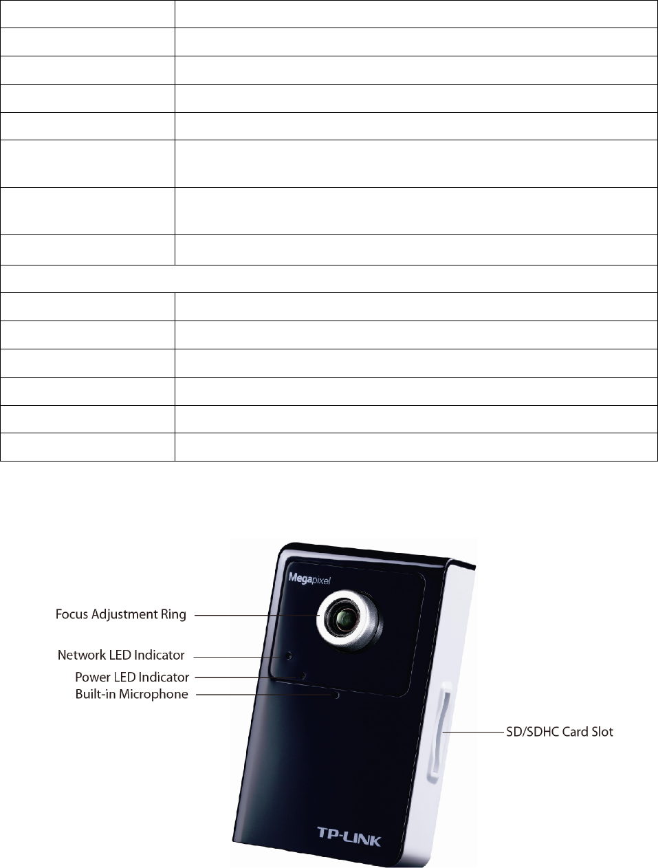
2.3.1 Front View
Focus Adjustment Ring: Adjust the focus ring to get a clear image.
Network LED Indicator: It lights up when the IP Camera is well connected to the network. It flashes
when there are data being transmitted.
Power LED Indicator
¾ Red: The IP Camera boots up.
¾ Blue: The IP Camera is working.
5
Built-in Microphone: The location where the voice from your partner comes out.
SD/SDHC Card Slot: Supports SD/SDHC memory card.
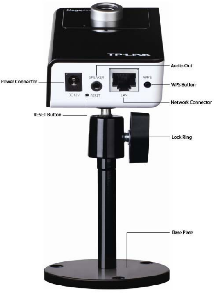
2.3.2 Bottom view
¾ Power Connector: The power connector is where you connect the power adapter.
¾ RESET: Please take the following steps to reset the camera to its defaults.
Keep the camera powered on, then press and hold the Reset button for more than 15 seconds.
Afterwards release it, and the Camera will be restored to factory defaults after rebooting.
¾ Audio Out: The Audio Out port is where the speaker is connected.
¾ LAN (Network Connector): Through this port, you can connect the IP Camera to your computer or
the other Ethernet network devices.
¾ WPS: Press this button to quickly establish a connection between the Camera and the router
supporting WPS (Wi-Fi Protected Setup).
6
Step 1. Press the WPS button on the router supporting WPS for 2 seconds.
Step 2. Press the WPS button on the Camera within 2 minutes.
¾ Lock Ring: It is used to adjust the angle of the Camera.
¾ Base Plate: It is used to support the Camera and can be fixed to a flat surface with the supplied
screws.
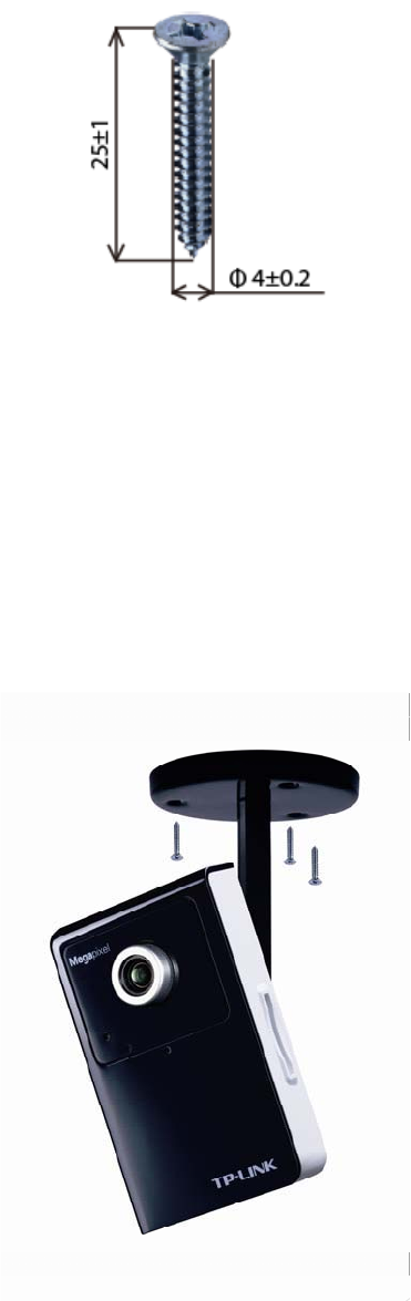
2.4 Mount the Camera
2.4.1 The Screw Size
There are three supplied screws for mounting the Camera. The length of the screws is 25f1 mm and
the diameter is 4f0.2 mm.
2.4.2 Wall and Ceiling Mount
1. Use the three supplied screws to fix the base plate to a flat surface.
2. Loosen the lock ring to adjust the desired angle of the Camera.
3. Tighten the lock ring.
There are two ways to mounting the Camera on the wall. See the following two pictures.
(1) Ceiling Mount
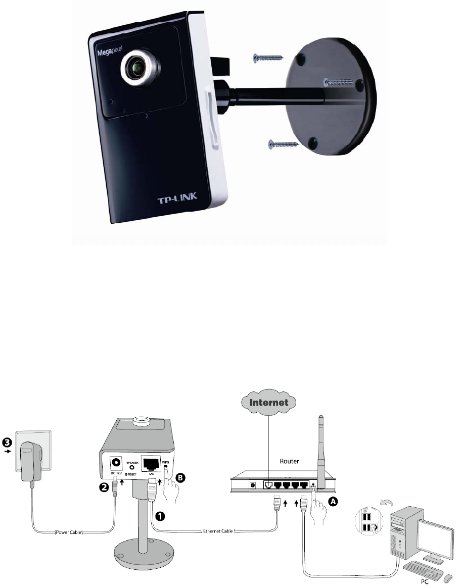
7
(2) Wall Mount
2.5 Hardware Connection
Before proceeding, confirm that your PC is connected to your router and can access the Internet. Make
sure that your router’s DHCP feature is enabled. If not, please refer to your router’s instruction to enable
it.
For TL-SC3430N, if your router supports WPS (Wi-Fi Protected Setup), you can also use WPS to setup
a wireless connection quickly. You can also choose Wired Connection.
Please connect the Camera according to the following steps.
2.5.1 Method 1: Wired Connection
1. Connect the Camera to the LAN network (Router or Switch) via Ethernet cable.
2. Connect the power adapter cord to the DC In jack.
3. Plug the power adapter into the power outlet.
8
2.5.2 Method 2: WPS Connection
Power on the Camera and make sure that the Power LED is blue before WPS Connection. Then take
the following steps.
A. Press the WPS button on the router supporting WPS for 2 seconds.
B. Press the WPS button on the Camera within 2 minutes.
After you press the WPS button on the Camera, the Power LED will turn purple and flash, and when the
WPS Connection is established successfully, it will return blue.
9
Chapter 3 Using IP Camera via Web Browser
3.1 Obtain the IP Address
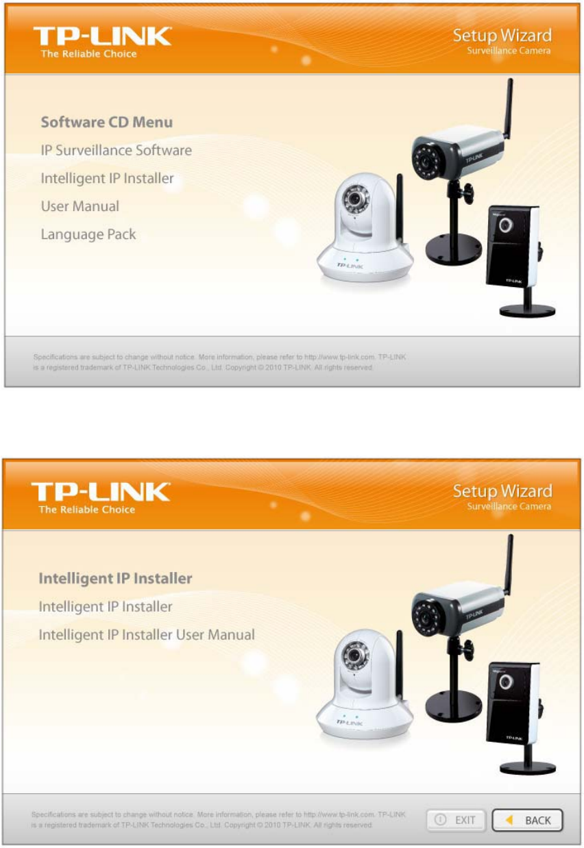
1. Insert the provided CD into your CD-ROM driver. The Setup Wizard will automatically pop up on
your computer’s screen as shown in the figure below.
Figure 3-1
2. Choose the Intelligent IP Installer, and then the next screen appears. Click on Intelligent IP
Installer to begin the installation.
Figure 3-2
10
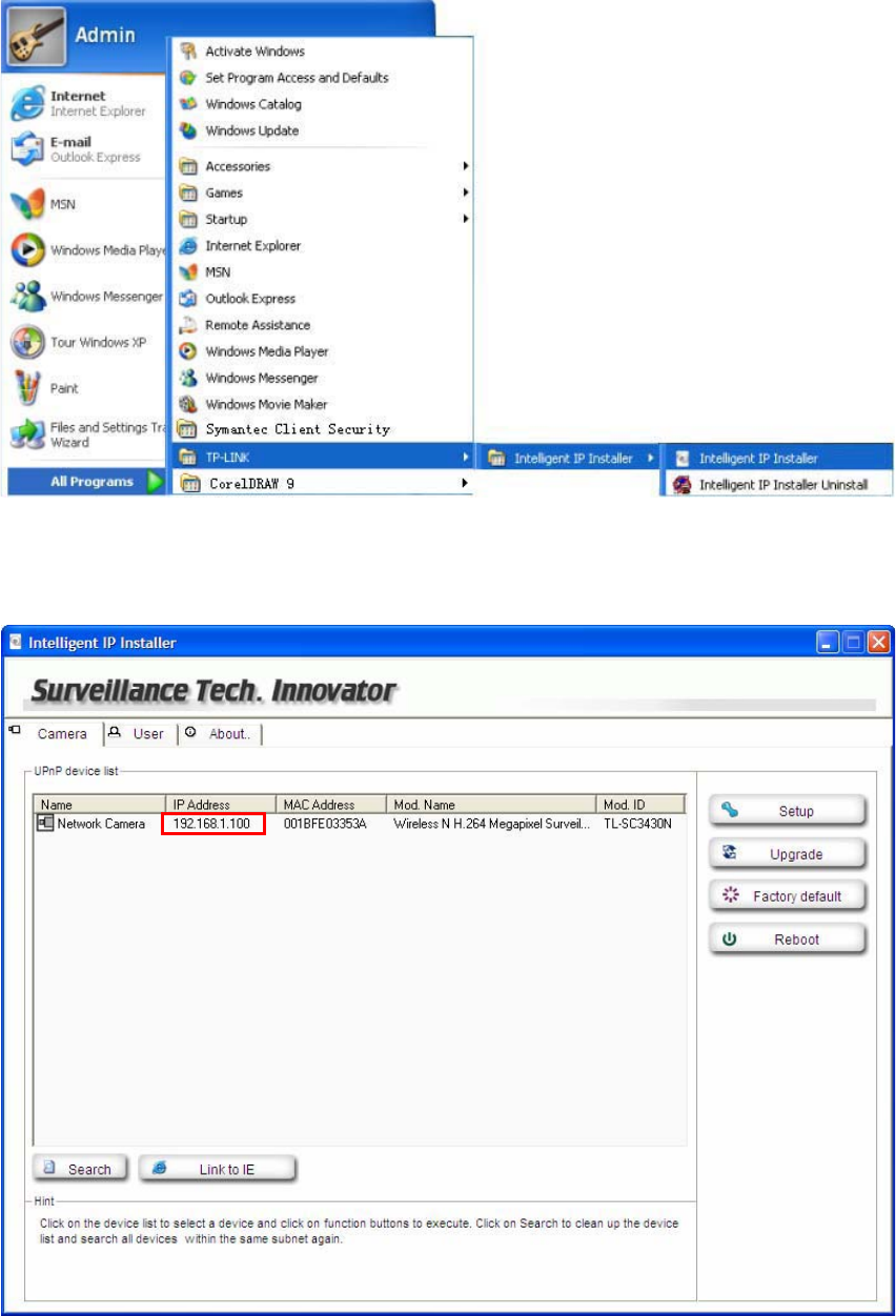
3. After the installation is finished, click Start > All Programs > TP-LINK >Intelligent IP Installer to
start using the program.
Figure 3-3
4. The following screen will then display. Click the Search button to search Network Cameras in the
network; it displays Network Cameras information including IP Address.
Figure 3-4
11
3.2 Windows Web Browser .2 Windows Web Browser
The configuration of browser is similar in Windows XP/Vista/7. Here we take IE browser in Windows XP
for example.
The configuration of browser is similar in Windows XP/Vista/7. Here we take IE browser in Windows XP
for example.
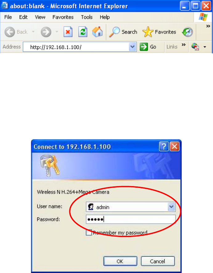
1 Click Link to IE button in Figure 3-4 directly. You can also launch your web browser and then enter
the IP address or host name of the IP camera in the Location / Address field of your browser.
1 Click Link to IE button in Figure 3-4 directly. You can also launch your web browser and then enter
the IP address or host name of the IP camera in the Location / Address field of your browser.
)
Note:
If you only want to view the video without accessing Setting screen, enter “http://<IP>/index2.htm” as
your web URL.
2 Use the default User name admin and default Password admin.
)
Note:
The default User name “admin” and the Password “admin” are set at the factory for the administrator.
You can change them in the Account Menu. (Please check “Setting Basic Security Account”)
3 The monitor image will be displayed in your browser. In the far left side of main configuration are
Setting, Client Setting, and Image Setup.
12
3.3 Mac Web Browser .3 Mac Web Browser
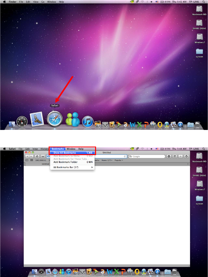
1 Click the Safari icon. 1 Click the Safari icon.
2 After the home page appears, click Bookmarks and then choose Show All Bookmarks.
13
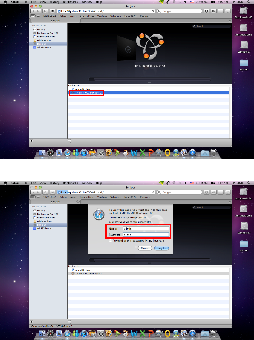
3 Click Bonjour on the left of the following screen. Double click the Mac address of the Camera in the
bookmark list. For example, TP-LINK-001BFE0334A2.
4 Enter the default Name admin and default Password admin. Click Log In.
)
Note:
The default user name “admin” and the password “admin”are set at the factory for the administrator. You
can change them in the Account Menu. (Please check “Setting Basic Security Account”)
14
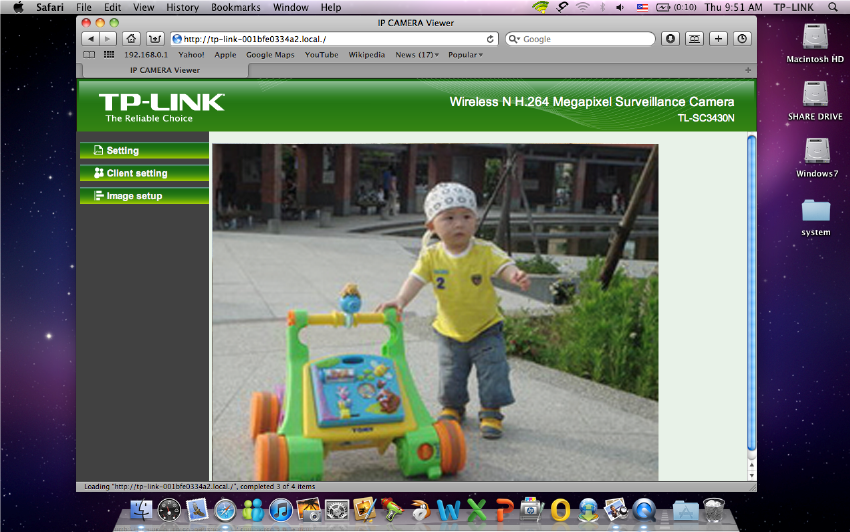
5 The monitor image will be displayed in your browser. In the far left side of main configuration are
Setting, Client Setting and Image Setup.
15
Chapter 4 Operating IP Camera via Mobile Phone
4.1 Mobile Phone Viewing
4.1.1 3G Mobile Phone Streaming Viewing
For 3G mobile phone viewing, type “rtsp://<IP>:<PORT>/video.3gp ” into your 3G Streaming Link. <IP>
is the Public IP address of your IP Camera; <PORT> is the RTSP port of your IP Camera (Default value
is 554.) Example: rtsp://100.10.10.1:554/video.3gp
)
Note:
You can also use RTSP clients (RealPlayer, VLC, QuickTime Player…etc.) to view RTSP streaming, just
type in “rtsp://<IP>:<PORT>/video.3gp” as the Player URL.
4.1.2 2.5G Mobile Phone WAP Viewing
For 2.5G mobile phone viewing, type “http://<IP>/mobile.wml” into your 2.5G WAP Browser. <IP> is the
Public IP address of your IP Camera.
4.1.3 2.5G Mobile Phone Browser Viewing
For 2.5G mobile phone viewing, type “http://<IP>/mobile.htm” into your 2.5G Web Browser. <IP> is the
Public IP address of your IP Camera.
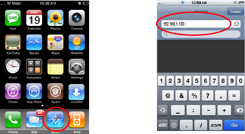
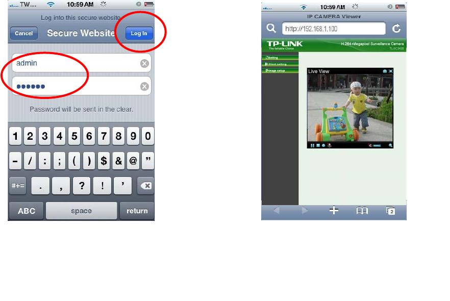
4.2 Using IP Camera via iPhone
You can use TP-LINK Web User Interface via iPhone. Please follow the setting process below. Then you
can use TP-LINK Web UI via iPhone.
1. Select Safari function 2. Enter IP address in
y
our web link.
16
4. The TP-LINK User Interface and live
image will show up in the middle of the
screen.
3. Enter name and password.
Default values are both admin.
Then click Lo
g
in
)
Note: It will show continuous snapshots
not a real time video streaming. Therefore, the
recording feature is disabled.
17
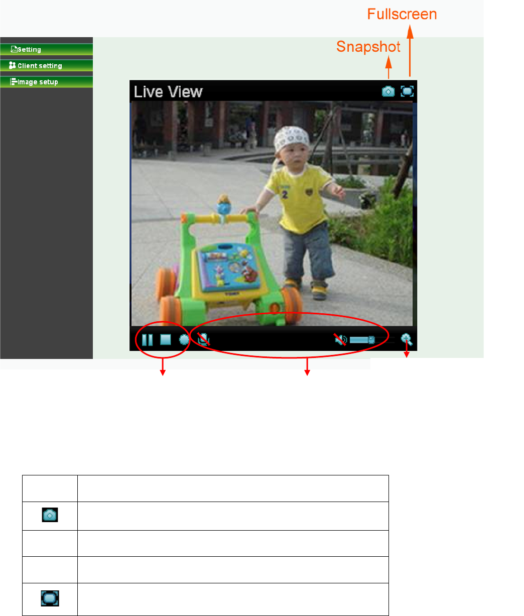
Chapter 5 Configuration of Main Menu
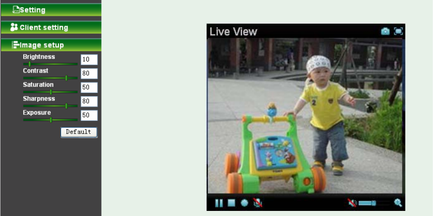
In the left side of main configuration are Setting, Client setting and Image setting.
In the right side, you can control Live View in your main Browser. The functions include: Snapshot,
Open digital zoom, Audio, and Video Play.
Video Play Audio Play
Open digital zoom
5.1 Live View
5.1.1 Snapshot
You can capture a still image shot by clicking the Camera icon and save it in the operating computer.
Symbols Meaning
a snapshot window appears after clicking the icon
Save Save the picture captured by snapshot into your computer
Close Return to the view screen
full Screen
18
5.1.2 Digital zoom in / out the image via the monitor window
x Click to display the digital zoom in window.
x Pull the to adjust the digital zoom range, and it will be
showed on the above window.
x Use the left click of your mouse to move to anywhere in the window area.
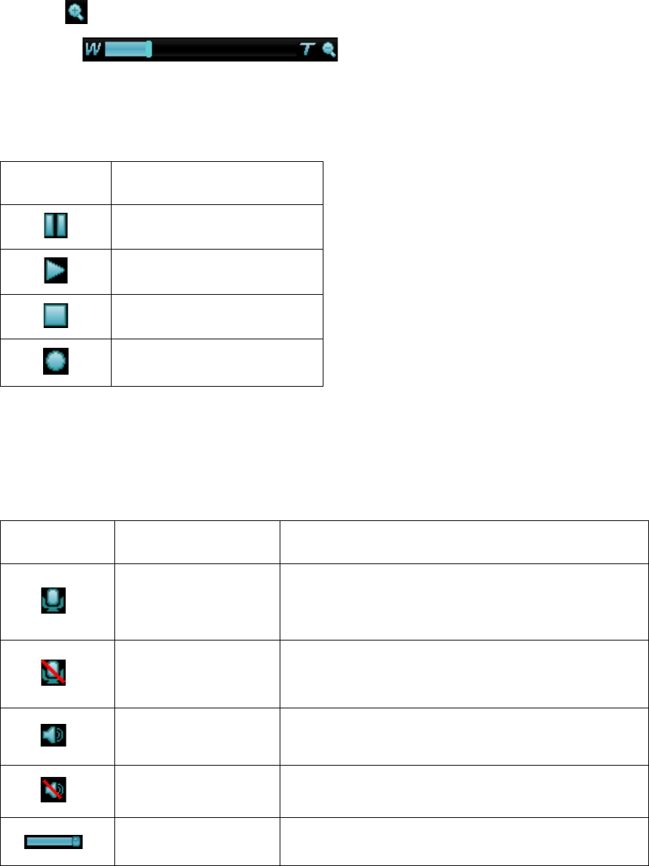
5.1.3 Video play buttons
Symbols Meaning
Pause the current video
Play the video
Stop the current video
Record the current video
)
Note:
Concerning the recording storage requirement of your hard disk, please refer to the CHAPTER 9.
APPENDIX / B. Storage Requirement Table.
5.1.4 Audio buttons
Symbols Meaning Note
Speakers turned on
mean the speakers of your computer are turned
on to transmit the sounds from the connected IP
camera(s)
Speakers turned off
mean the speakers of your computer are turned
off to transmit the sounds from the connected IP
camera(s)
Mute off
mean you can broadcast to the connected IP
camera(s) via the Ethernet using your microphone
Mute on mean you can’t broadcast to the connected IP
camera(s) via the Ethernet using your microphone
Volume control bar mean you can adjust the sound volume by the
control bar
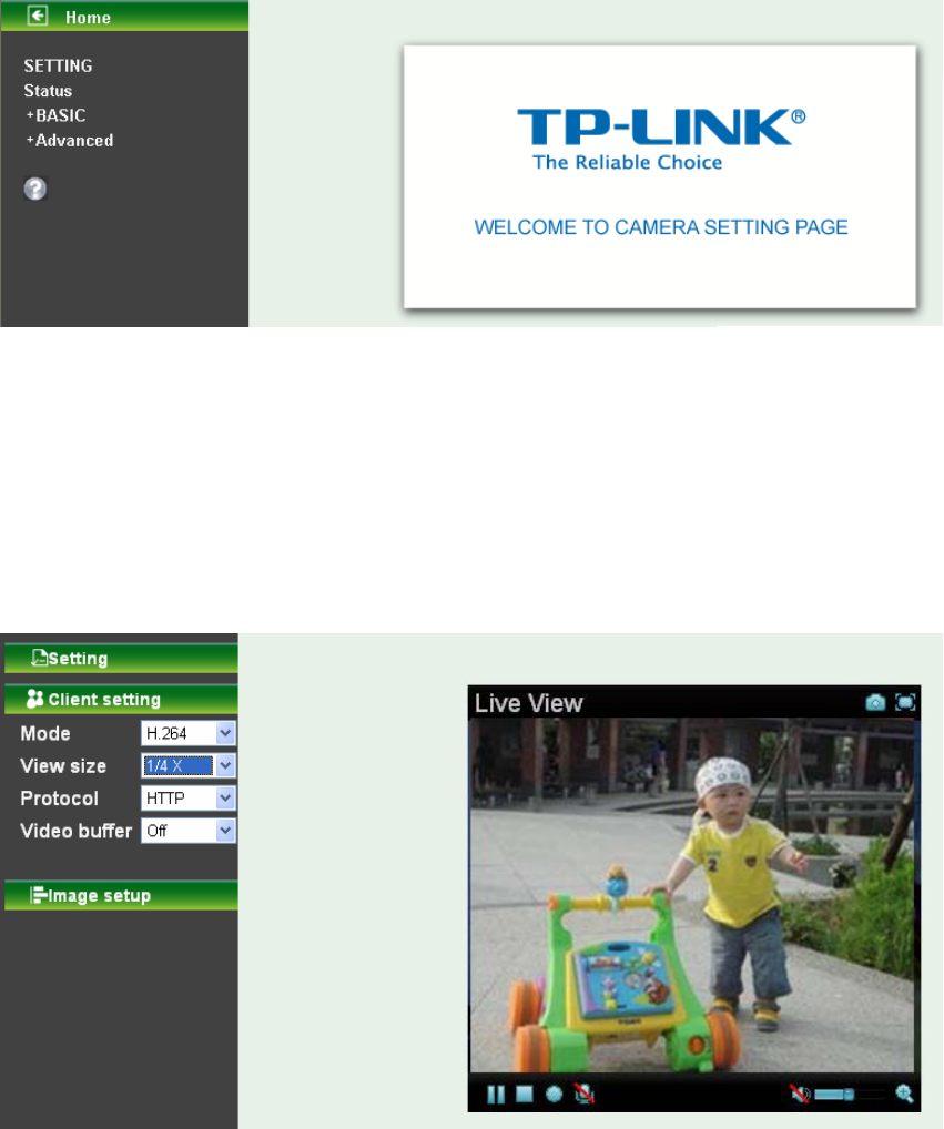
5.2 Setting
This function is only for the Administrator. Click “Setting” on the home page of web user interface to get
into the Basic and Advanced Settings menu.
19
Click Basic folder, there are sub-folders including System, Camera, Network, and Security. Fore more
information, you can see Chapter 6.
Click Advanced folder, there are sub-folders including FTP Client, SMTP, Network Storage, Memory
Card, HTTP event, Schedule, Alarm buffer, Motion detection, Audio detection, and System Log.
Fore more information, please see Chapter 7.
5.3 Client Setting
This function is only for the client. Click this button to control Mode, View size, Protocol, and Video
buffer.
5.3.1 Mode
Click the pull-down box to choose video compression mode of LIVE VIEW among H.264, MPEG4, and
JPEG.
)
Note:
As long as the operating system not able to afford loading under H.264 mode, please downgrade the
mode to MPEG-4 or MJPEG.
5.3.2 View Size
Select the desired view size of image resolution among 1/4X, 1/2X, and 1X.
5.3.3 Protocol
Select the transferring protocol among TCP, UDP, and HTTP.
20
5.3.4 Video Buffer .3.4 Video Buffer
Turn the Video Buffer function On / Off. The Video Buffer function makes the streaming more smooth in
unsteady network environment, but might cause a little delay in live viewing.
Turn the Video Buffer function On / Off. The Video Buffer function makes the streaming more smooth in
unsteady network environment, but might cause a little delay in live viewing.
5.4 Image Setup 5.4 Image Setup
The tool bar can be adjusted to optimize video Brightness, Contrast, Saturation, Sharpness and
Exposure.
The tool bar can be adjusted to optimize video Brightness, Contrast, Saturation, Sharpness and
Exposure.
5.4.1 Brightness
The value range is 0~99. The higher value the brightness is, the brighter the image is.
5.4.2 Contrast
The value range is 0~99. The contrast is a measure of a display system, defined as the ratio of white to
black that the system is capable of producing. The higher value the contrast is, the more delicate of color
you can have.
5.4.3 Saturation
The value range is 0~99. The saturation of a color is determined by a combination of light intensity and
how much it is distributed across the spectrum of different wavelengths. The higher value the saturation
is, the more colorful the image will be.
5.4.4 Sharpness
The value range is 0~99. It applies image processing techniques to adjust the sharpness of live view.
However, the higher the value is, more the noise is.
5.4.5 Exposure
The value range is 0~99. The higher value the exposure is, the brighter the image is.
5.4.6 Default
After the adjustment of all setting, you can still click Default to make the setting back to the original
setting.
21
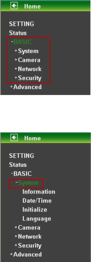
Chapter 6 Setting-Basic
Click the Basic folder to display the sub folders including System, Camera, Network, and Security.
6.1 System
Click the folder of System to display the sub-folders including Information, Date / Time, Initialize, and
Language.
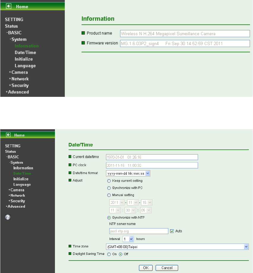
6.1.1 Information
The Information screen provides the product factory information which includes Product Name,
Firmware Version.
22
6.1.2 Date / Time
The Date/ Time screen displays all options of time setting.
¾ Current Date / Time: This displays the current date and time of this IP Camera.
¾ PC Clock: This displays the date and time of the monitoring PC clock.
¾ Date / Time Format: You can click the pull down box to select different time display formats.
)
Note:
If you would like the Date / Time information shows on the Live View screen, please check “Setting
Basic Camera General Date / Time ” to execute the setting.
¾ Adjust: You can select one of those four adjusting modes for your IP Camera.
z Keep current setting: Select this mode to keep the current date and time of this IP
Camera.
z Synchronize: Select this mode to keep the date and time of this IP Camera is the same as
the monitoring PC.
z Manual setting: Select this mode to adjust manually the date and time of this IP Camera.
z Synchronize with NTP: Specify the NTP server name and the Refresh Interval to
synchronize the date and time of this IP Camera with those of the time server, known as the
NTP server.
¾ Time Zone: Select the Time Zone format of Greenwich Mean Time among different cities. The
23
time display will be the same as the current date / time option.
¾ Daylight Saving Time: There are two modes to choose for setting up daylight saving time.
z By Date: Set the start and end time by select month, day, hour, and minute.
z By Week Number: Set the start and end time by select month, week, hour, and minute.
)
Note:
The NTP server (Network Time Protocol) is the time server which is an Internet standard protocol built on
the top of TCP / IP. This assures accurate synchronization to the millisecond of computer clock times in a
network of computers.
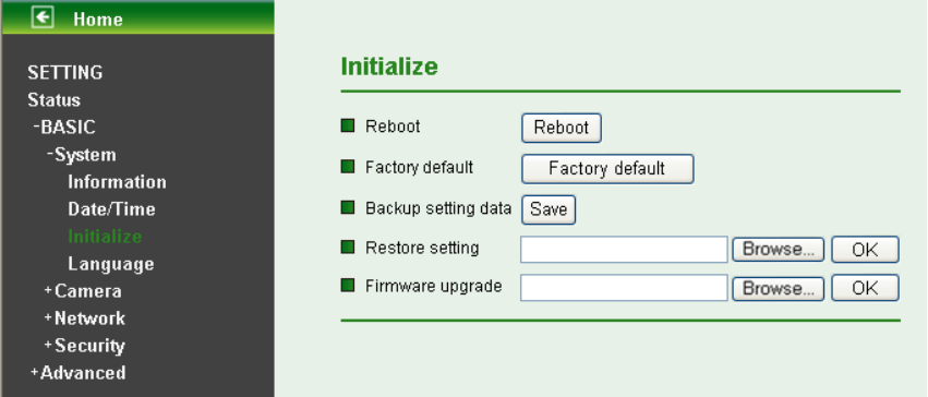
6.1.3 Initialize
¾ Reboot: Click this button to reboot this IP Camera. A confirmation dialogue will appear and then
click “OK” to execute. It takes one minute to complete the reboot process.
¾ Factory Default: Click this button to recover this IP Camera to the factory default setting. A
confirmation dialogue will appear and then click “OK” to execute. The network indicator on this IP
Camera will start to blink. This IP Camera will reboot automatically after completing adjustments
to the default setting. Don't turn off this IP Camera until the device reboots.
¾ Backup Setting: You can save the setting data of this IP Camera into a file. Click “Save” and
follow the instructions on the browser to save the setting data file to the location you specified.
¾ Restore Setting: Download the saved setting data of this IP Camera. Click “Browse” and select
saved file. Click “OK” and this IP Camera is adjusted according to the loaded data and then
restarted.
¾ Firmware Update: Update the device software. Click “Browse” and select the file for updating. A
confirmation dialogue will appear. Click “OK” to start. This IP Camera will reboot upon completion.
)
Note:
When updating the firmware version, please use the file specific for the model. Otherwise, some
problems may occur. Unless the updating completed, please don’t turn off the power or disconnect the
network.
24
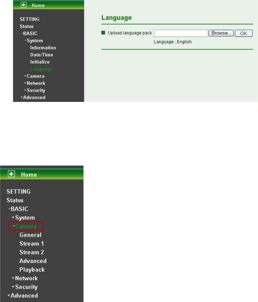
6.1.4 Language
¾ Upload Language Pack: Clicking “Browse” and selecting the file for updating, the present
language display of WEB User Interface could be changed. A confirmation dialogue will appear.
Click “OK”, then the update will be applied immediately. The default language is “English”.
6.2 Camera
Click the folder of Camera to display the sub folders including General, Stream 1, Stream 2, Advanced
and Playback.
25
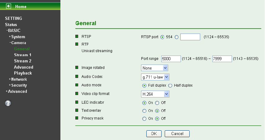
6.2.1 General
¾ RTSP: The default value is 554. If the IP Cameras connected with router and installed outside
are over 2 sets and all of them need support RTSP, please fill some value in the blank space in
the range from 1024 to 65535.
¾ RTP Unicast streaming: The default value of port range is 5000 ~ 7999 and can be changed
from 1024 to 65535.
)
Note:
Under Unicast streaming mode, streaming video is delivered from the Camera to a single client device.
¾ Image rotated: Select the screen display “None”, “Flip”, “Mirror”, or “Mirror + Flip.”
¾ Audio Codec: Select one audio codec among G.711 U-law / G.711 A-law / AMR Audio / Off.
z G.711 U-law: one codec for “Computer Audio”, used in North America & Japan areas.
z G.711 A-law: another codec for “Computer Audio”, used in Europe and the rest of the world.
z AMR Audio: an audio codec of the third generation communication for MOBIL
z Off: Select Off, audio file won’t be transmitted by IP CAM.
¾ Audio Mode: You can select Full duplex or Half duplex.
z Full duplex: Select it for simultaneous communication in both direction between the
connected administrator and IP CAM. It means both parties can speak and be heard at the
same time.
z Half duplex: Select it for communication in both directions, but only one direction at a time
(not simultaneously). It means one party begins receiving a signal, it must wait for the
transmitter to stop transmitting, before replying. Therefore, once one party speak, he can’t
hear any voice from the other party, just like the communication by radio set.
¾ Video Clip Format: Select RECORDING compression format H.264 or MPEG-4.
z MPEG-4: MPEG-4 has the advantage of sending a lower volume of date per time unit
across the network (bit-rate) compared to Motion JPEG and therefore provides a relatively
high image quality at a lower bit-rate (bandwidth usage).
z H.264: H.264 provides higher compression rate than MPEG-4. Thus, H.264 can decrease
the bandwidth usage and further apply on 3G. However, H.264 will occupy more system
resources than MPEG-4. As long as the operating system appears operating difficulties
under H.264 format, please change to select MPEG-4.
¾ LED Indicator: The status of the LED indicatiors on the Camera. It’s turne on by default.