TP Link Technologies SC3430N Wireless N H.264 Megapixel Surveillance Camera User Manual TL SC3430N User Guide
TP-Link Technologies Co., Ltd. Wireless N H.264 Megapixel Surveillance Camera TL SC3430N User Guide
Contents
- 1. User Manual 1
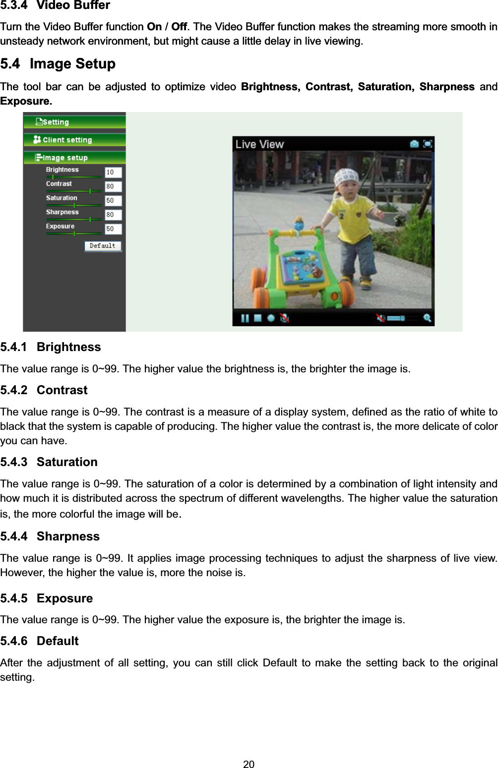
- 2. User Manual 2
- 3. User Manual 3
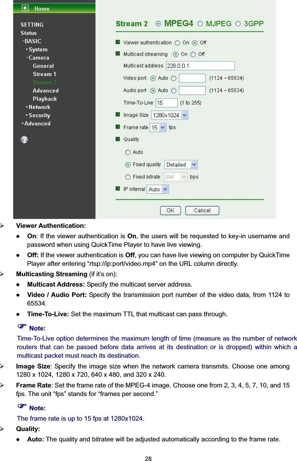
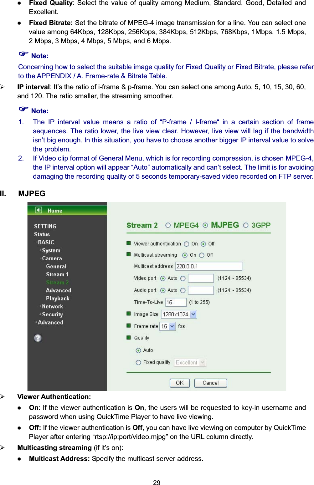
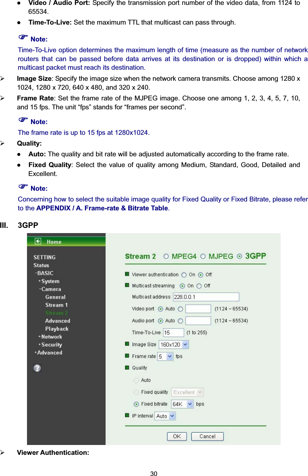
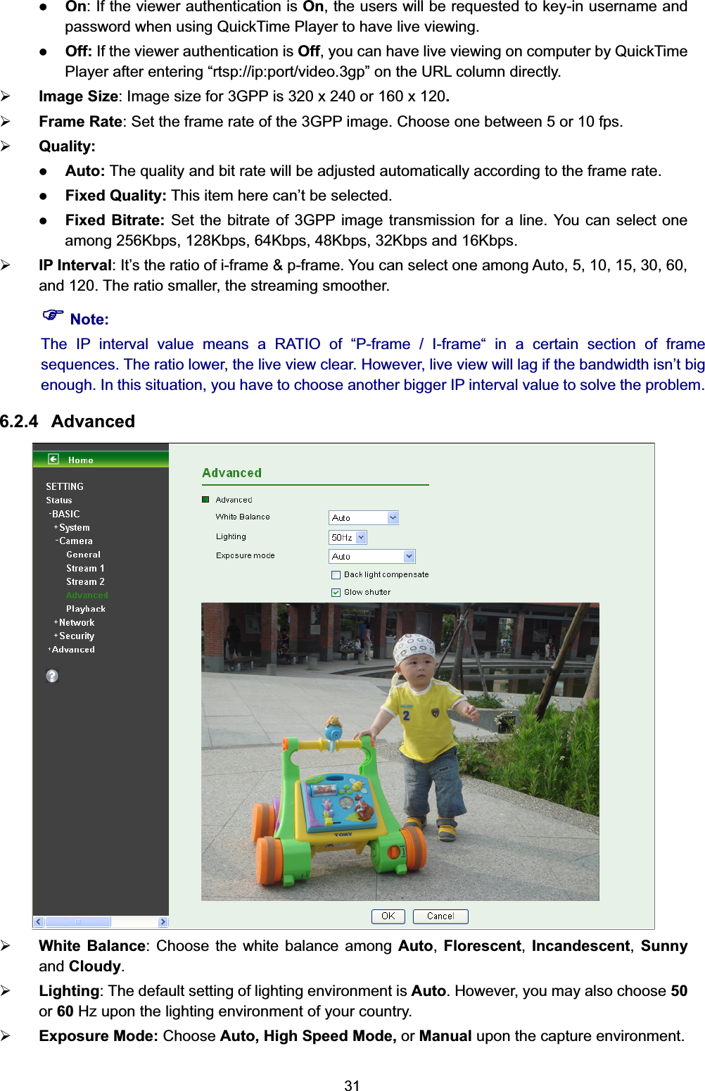
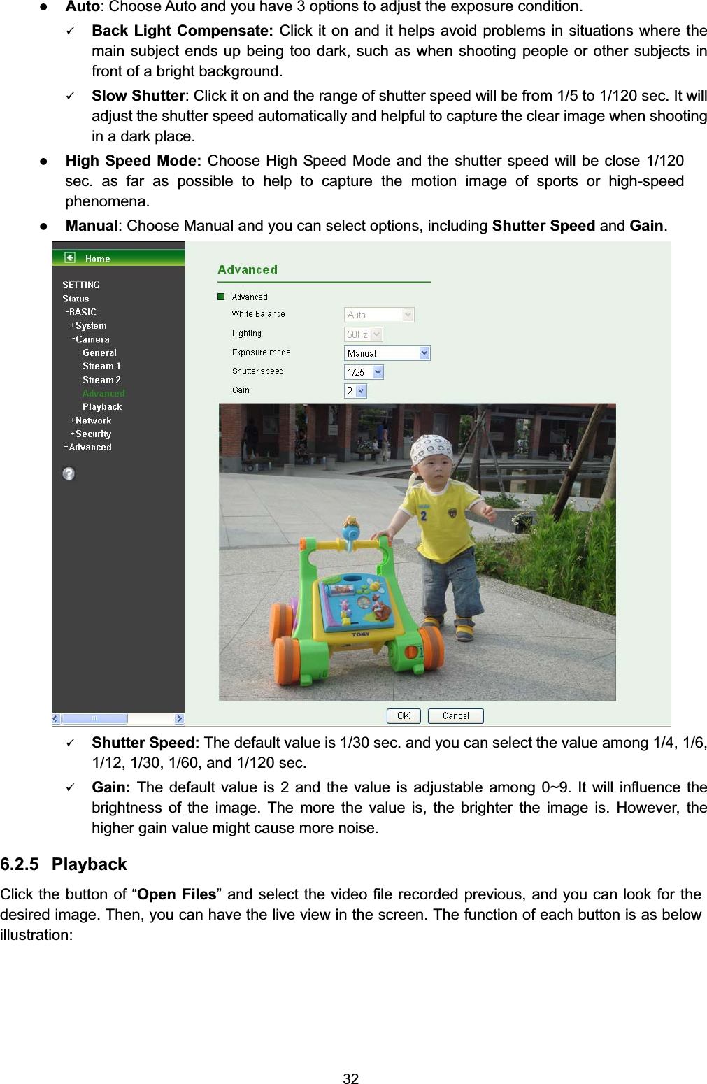
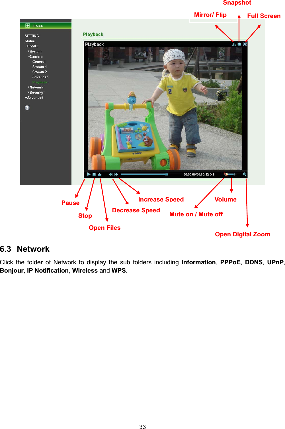
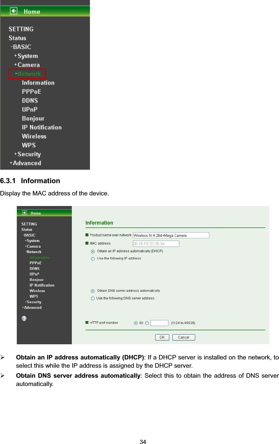
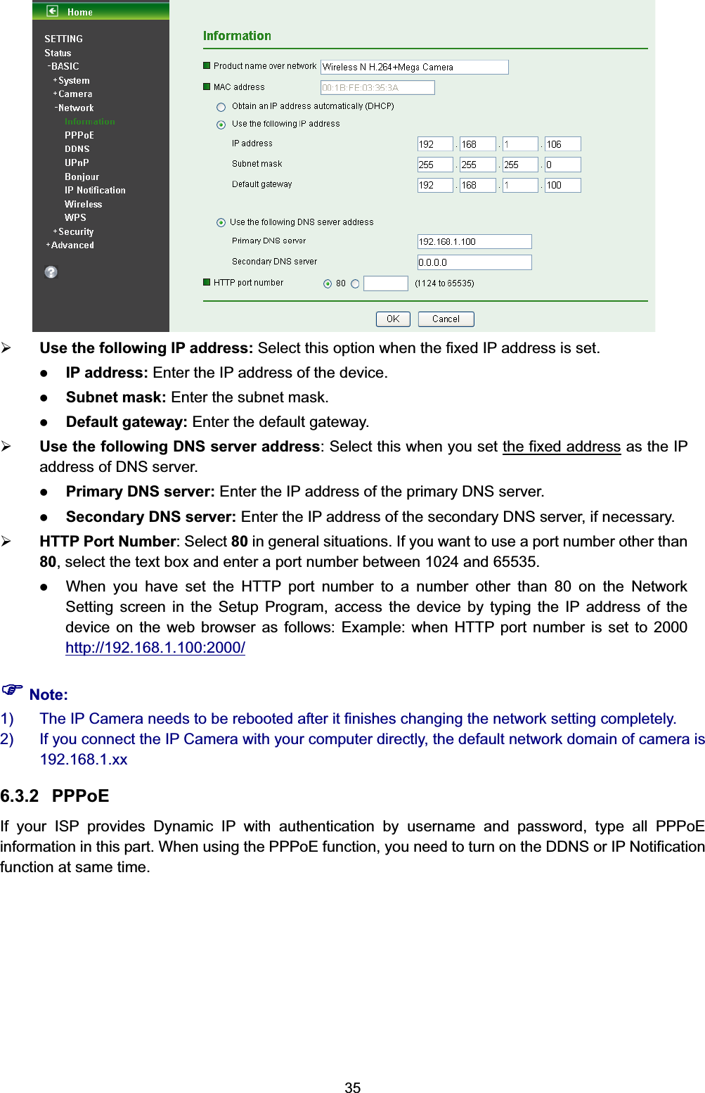
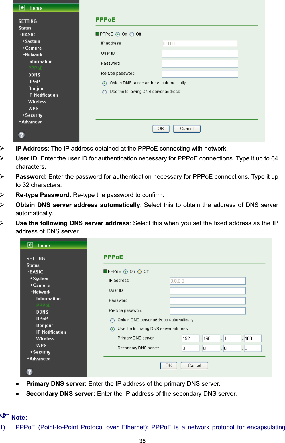
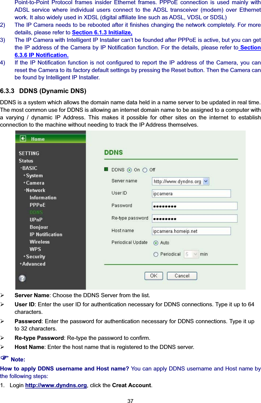
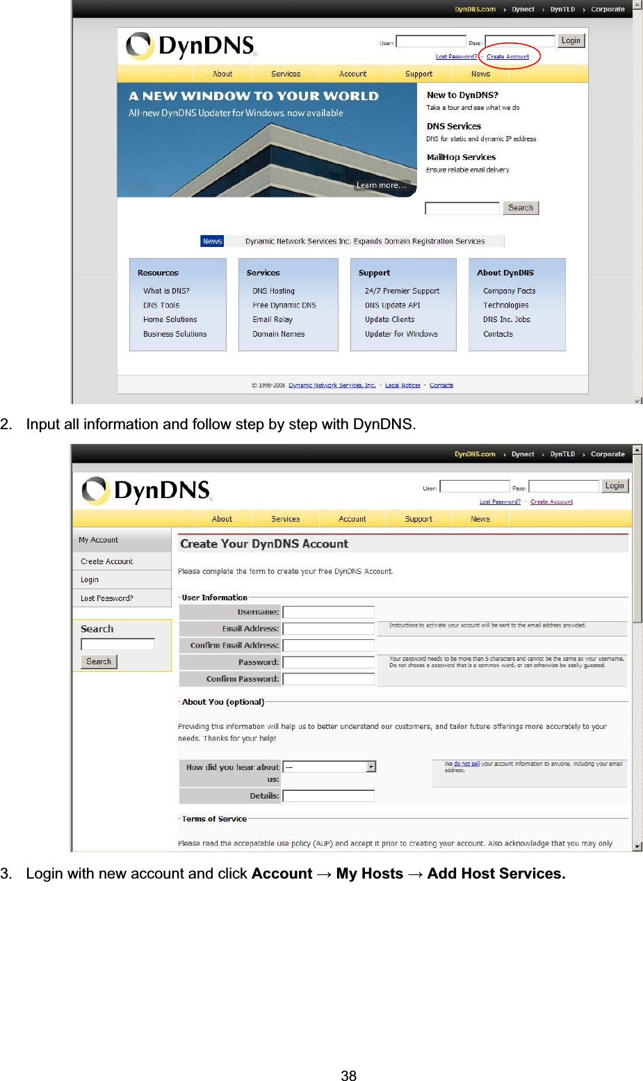
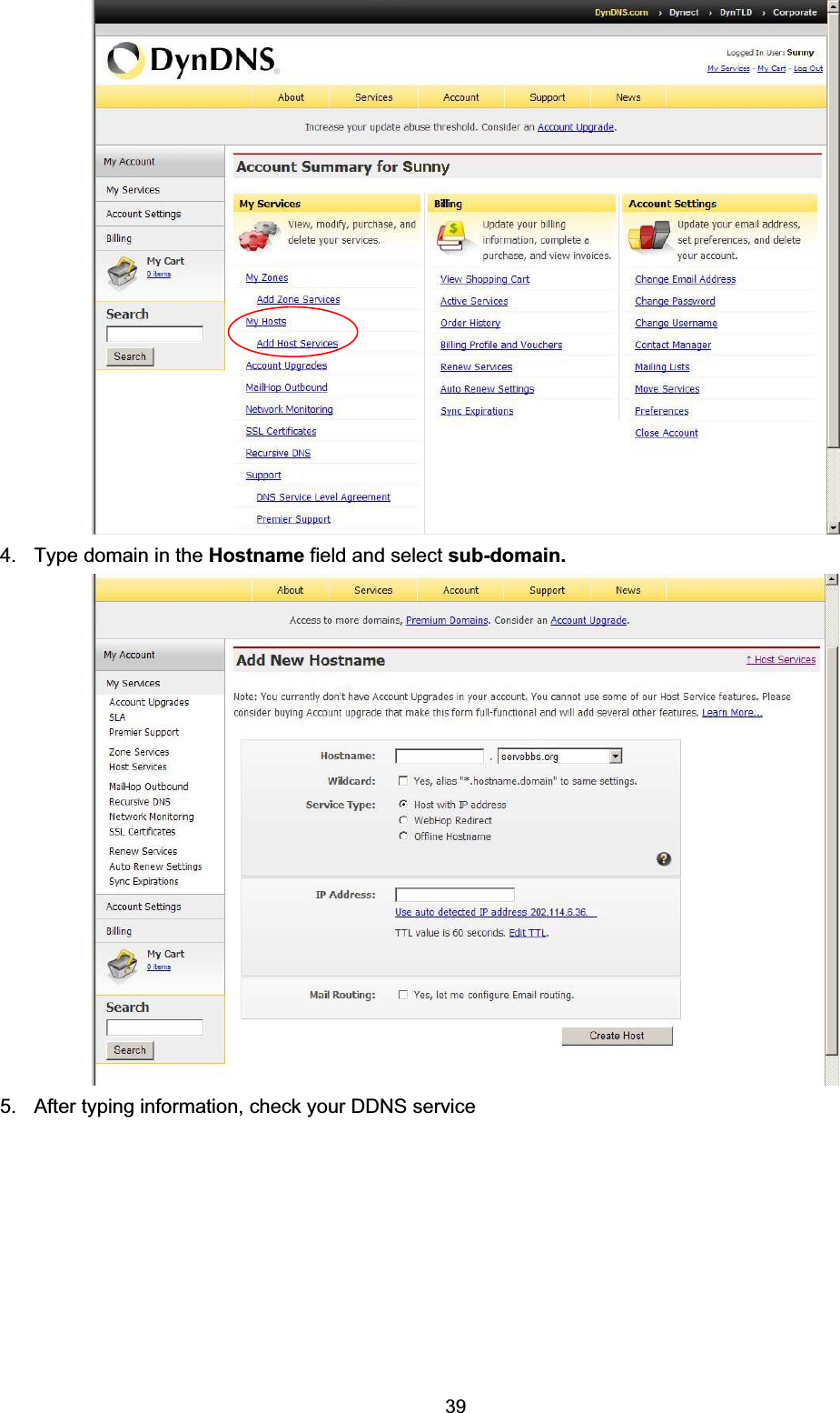
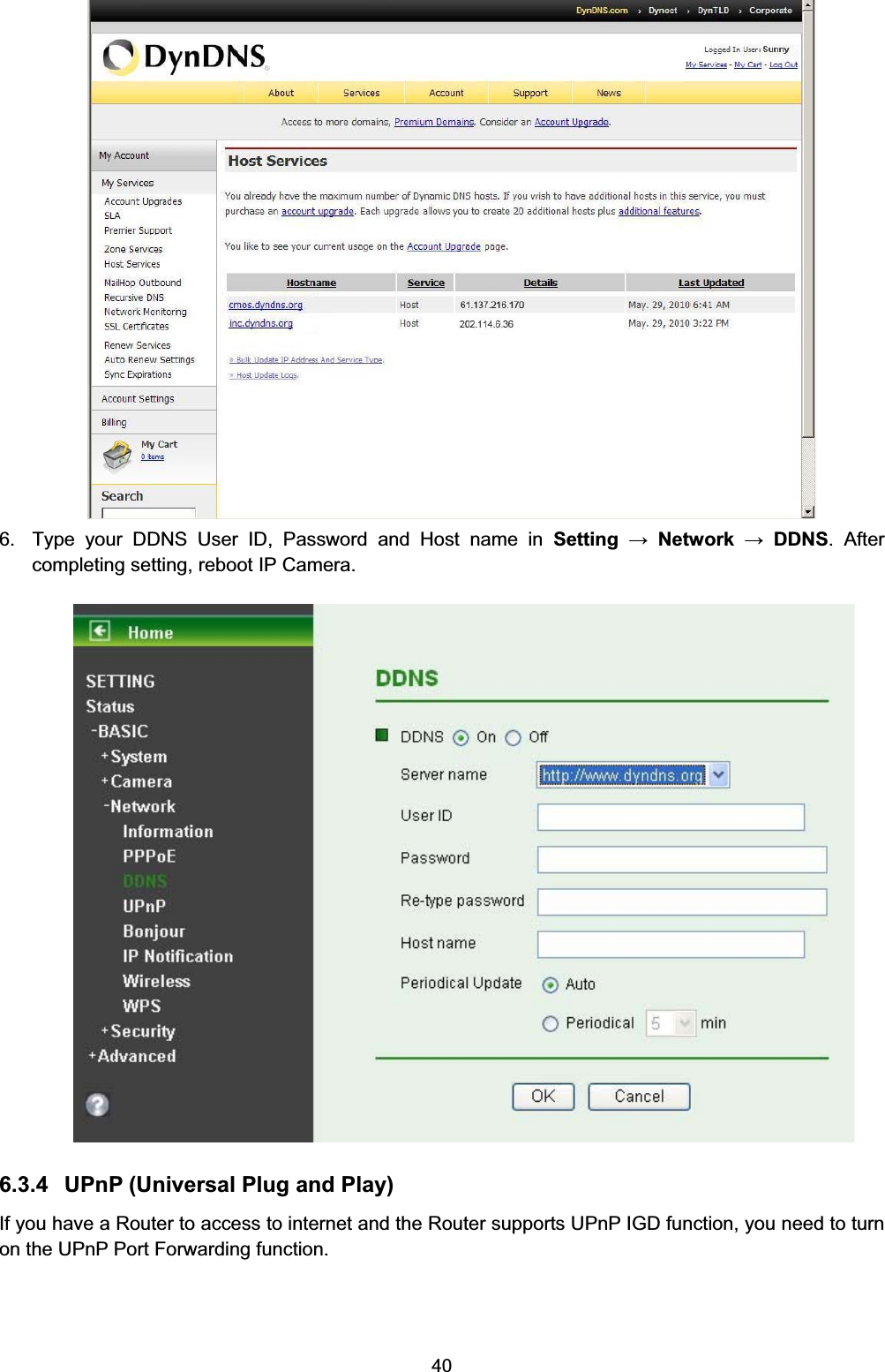
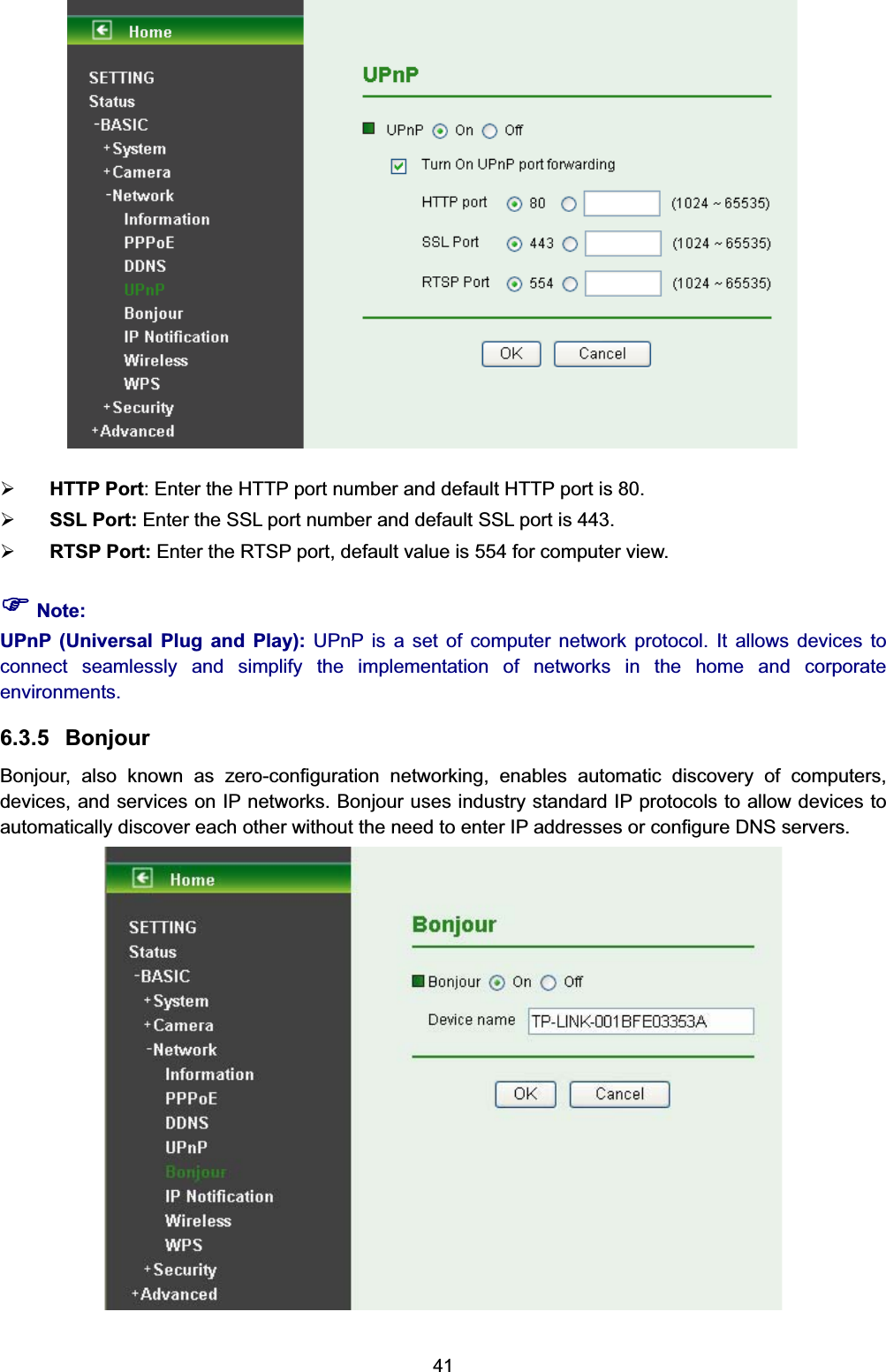
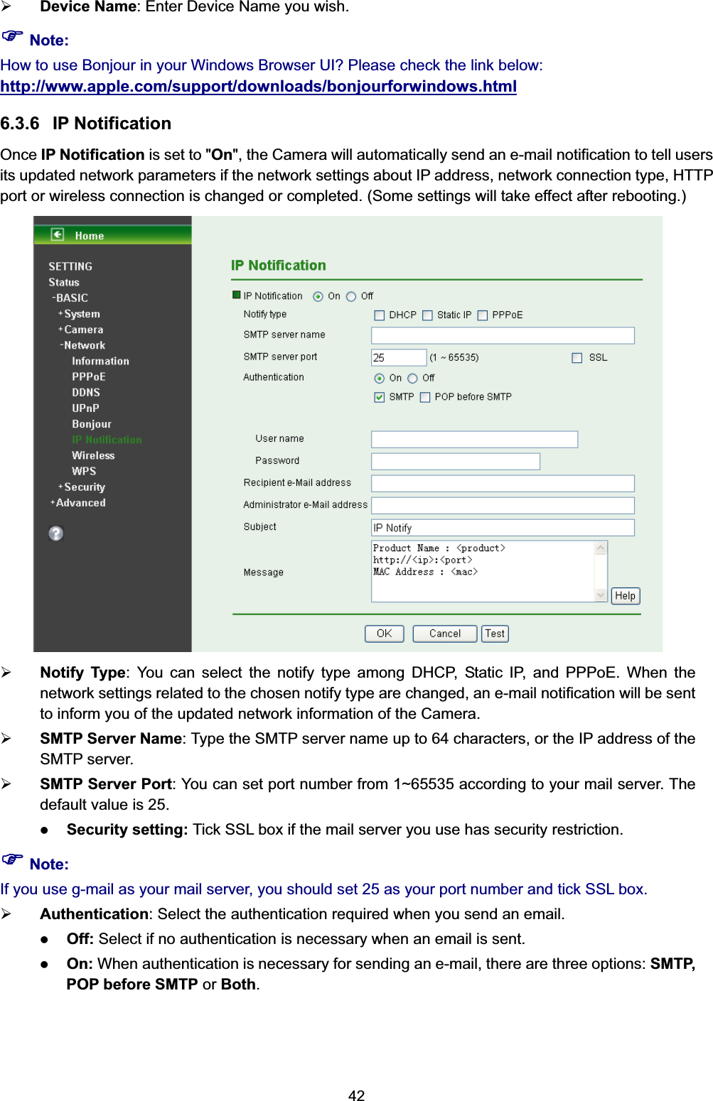
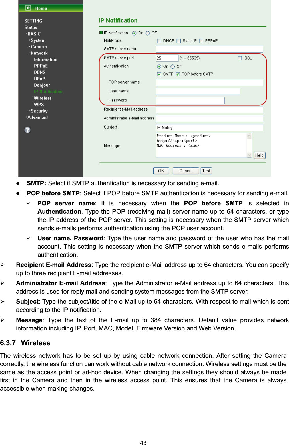
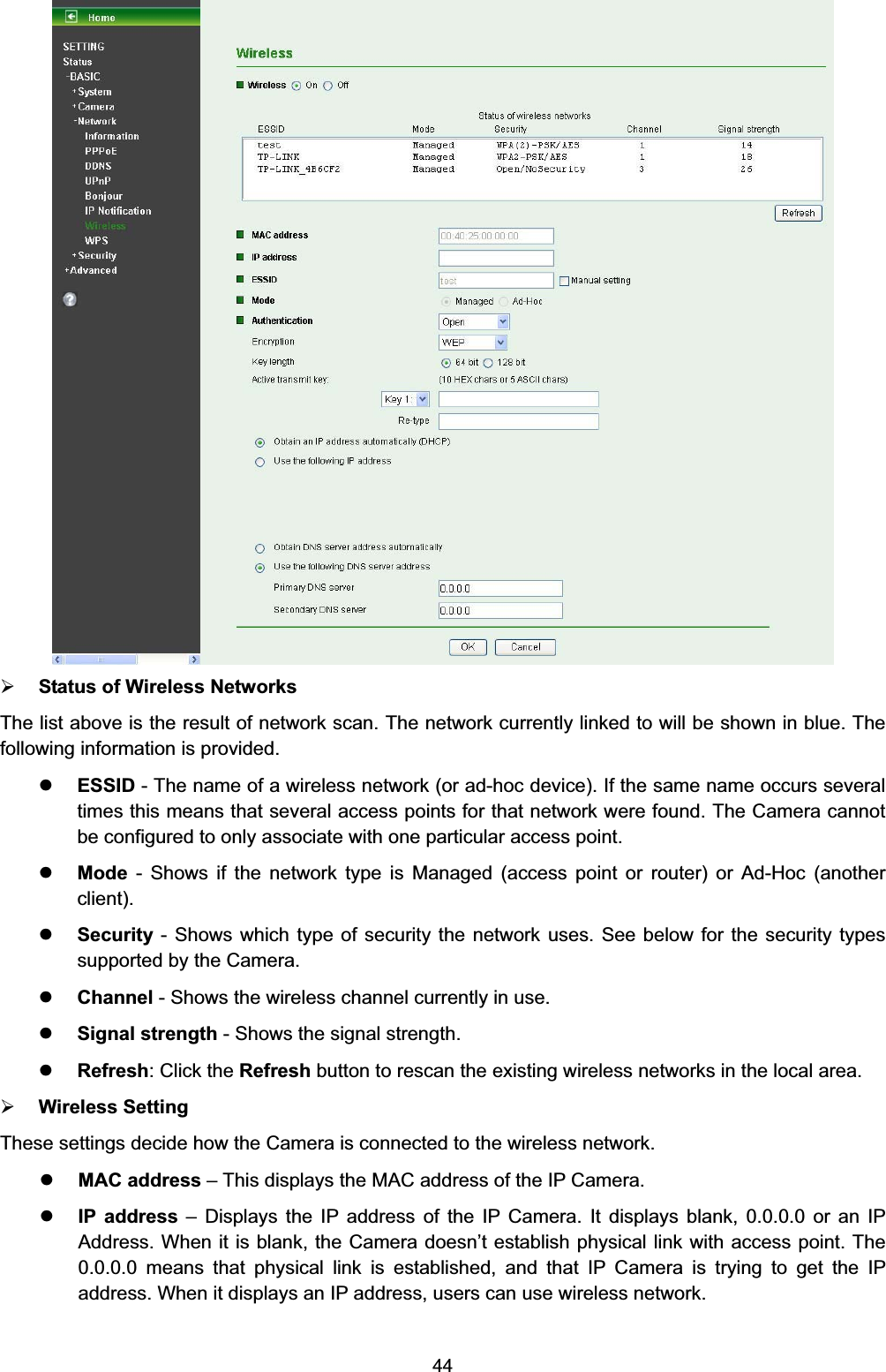
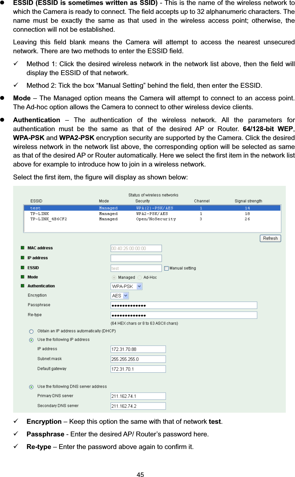
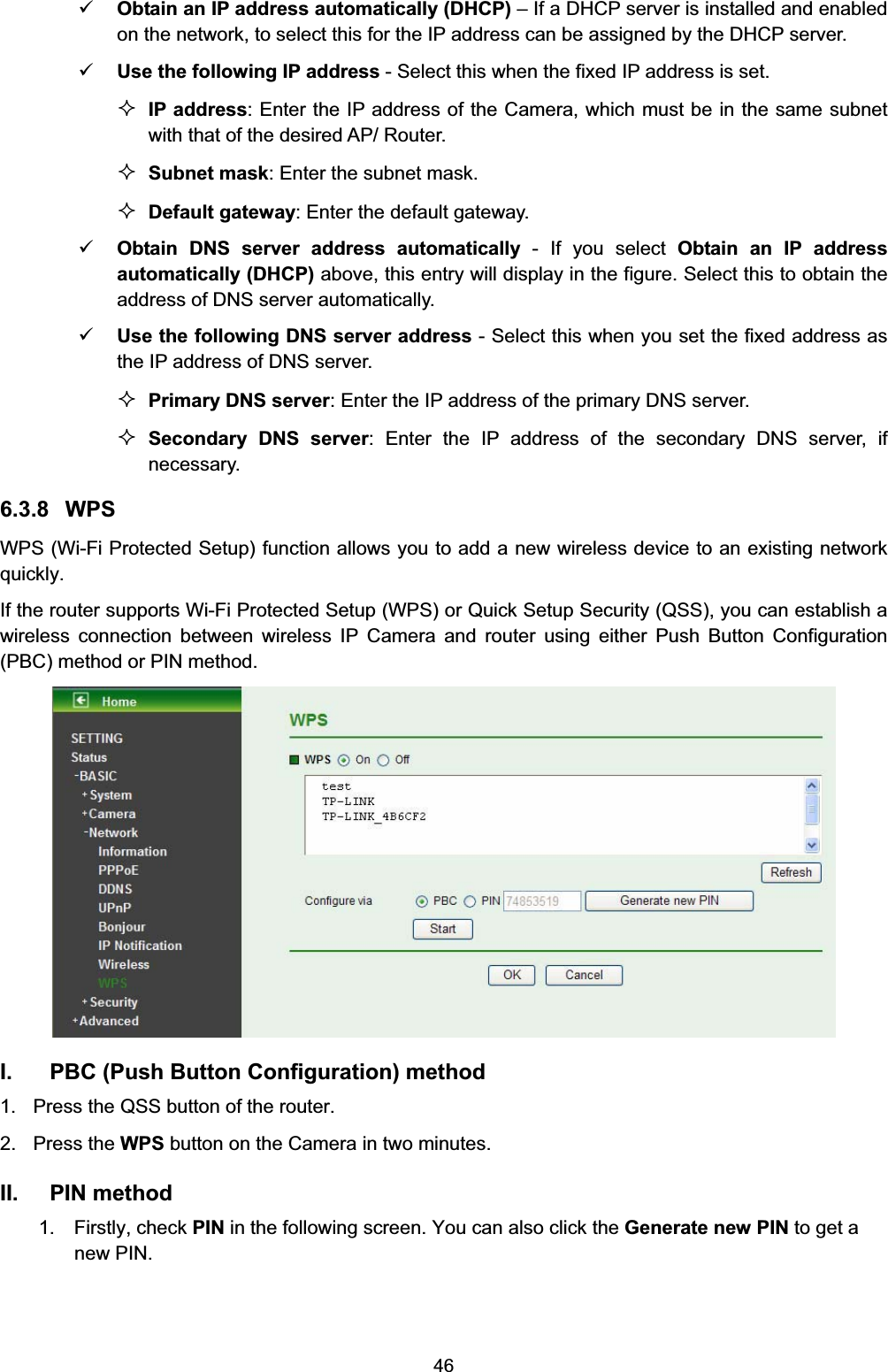
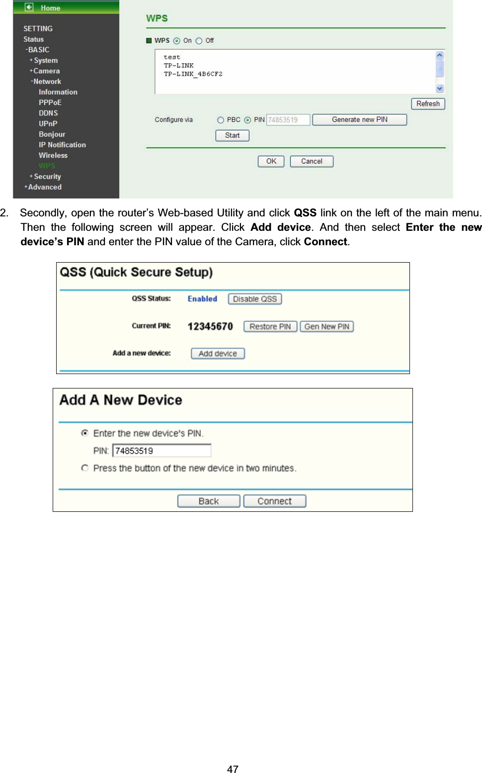
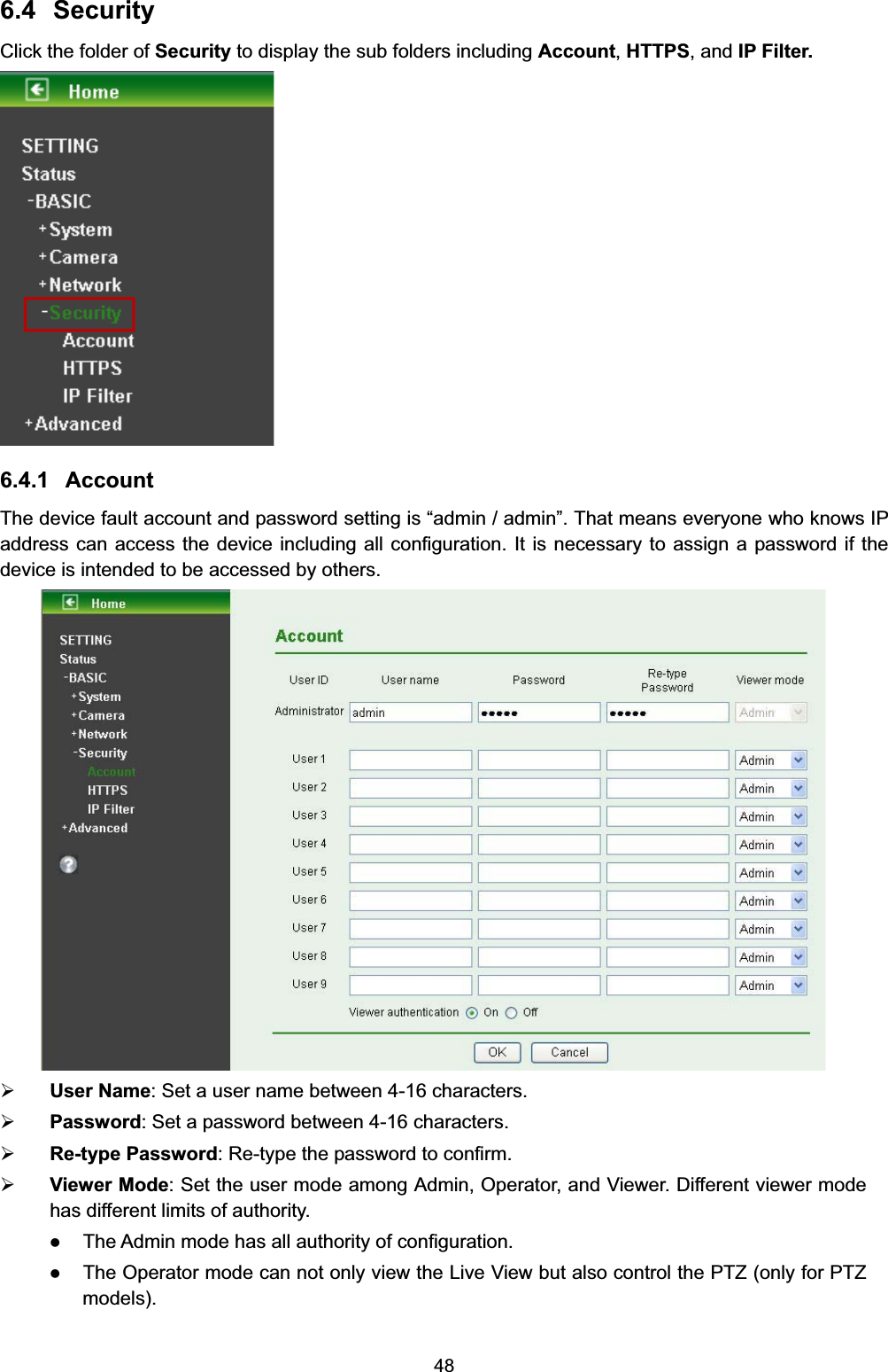
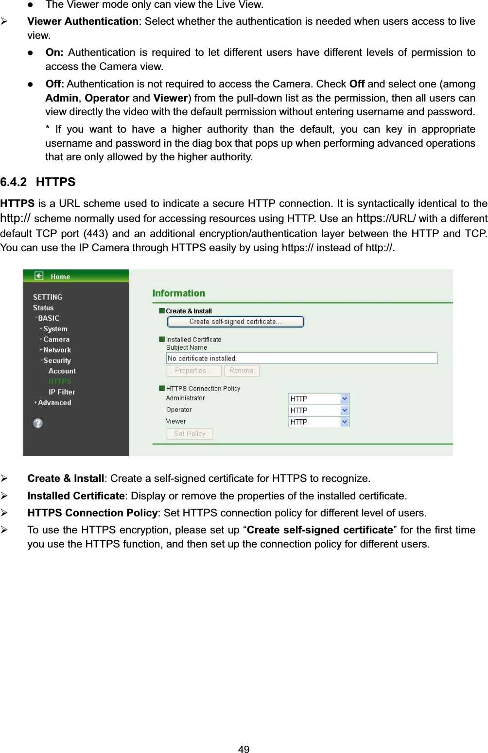
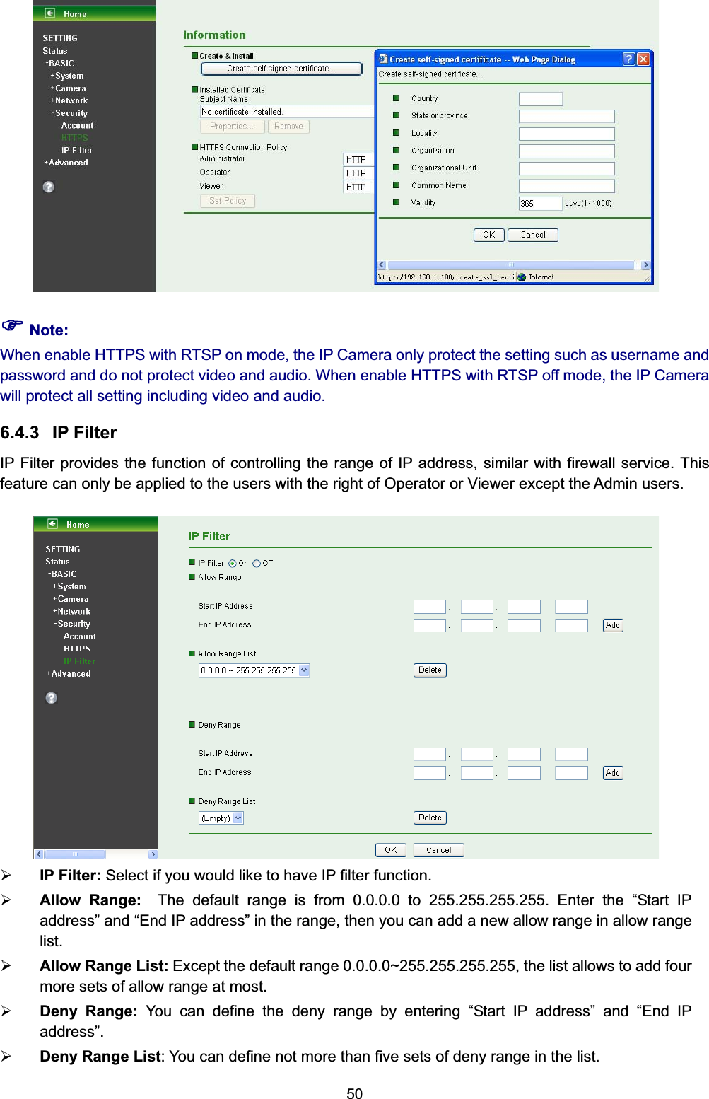
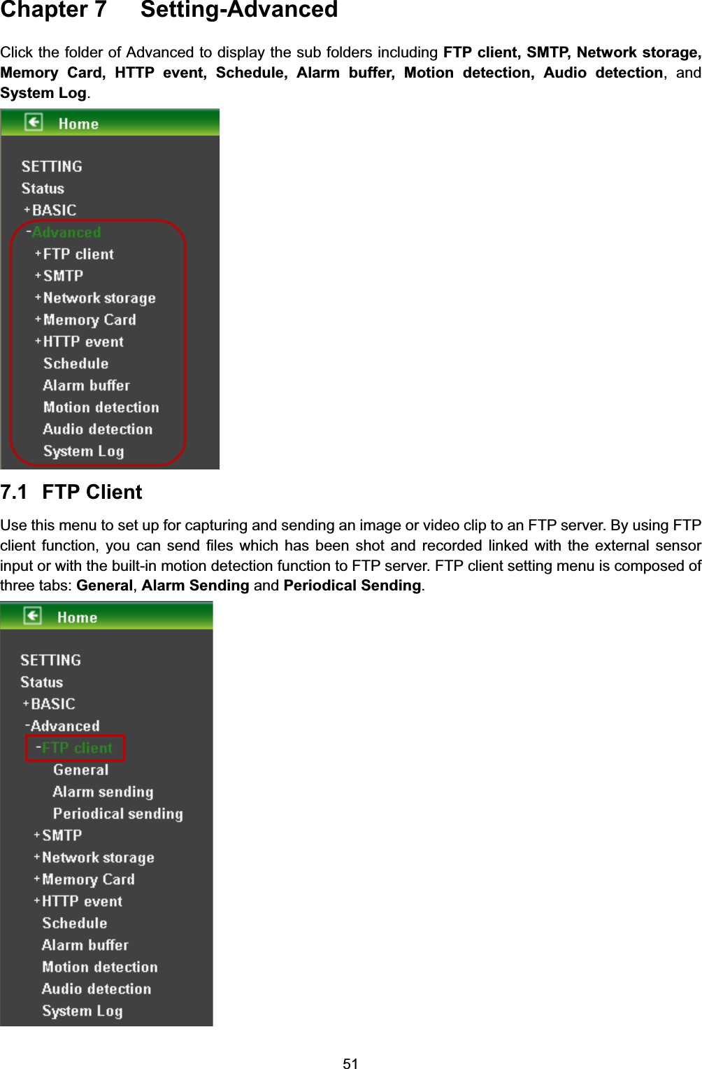
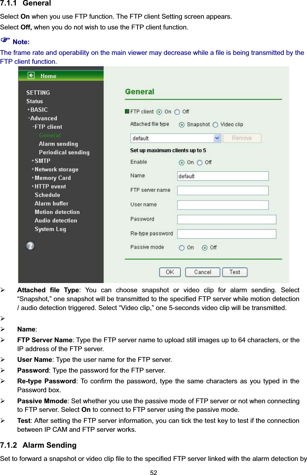
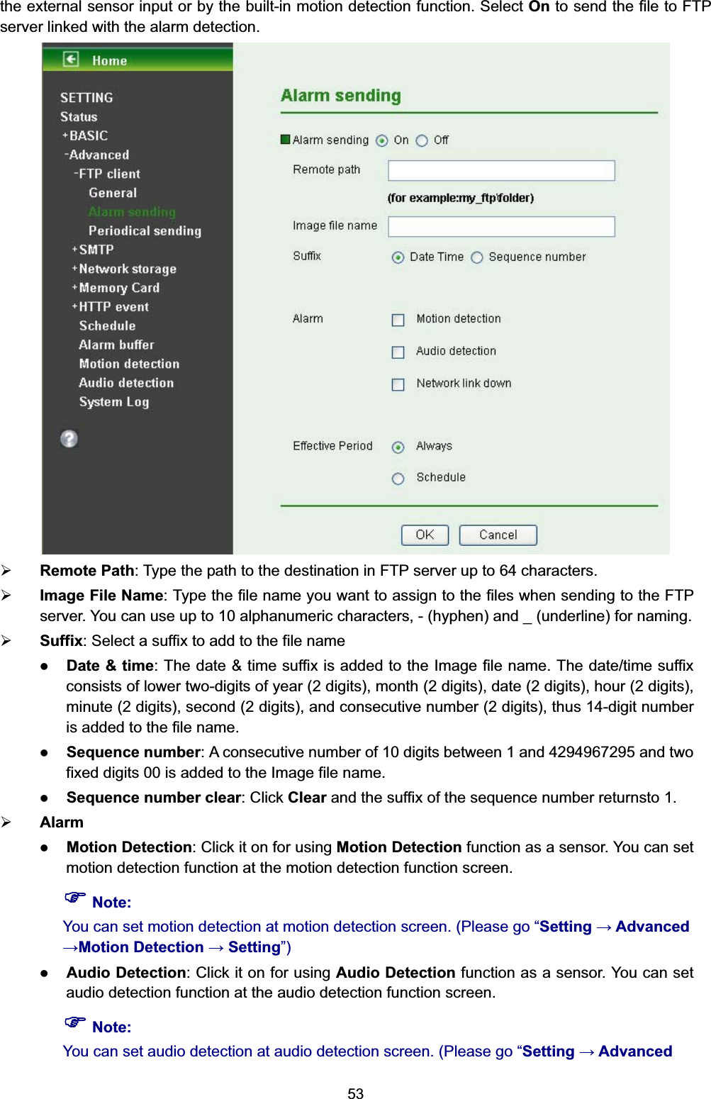
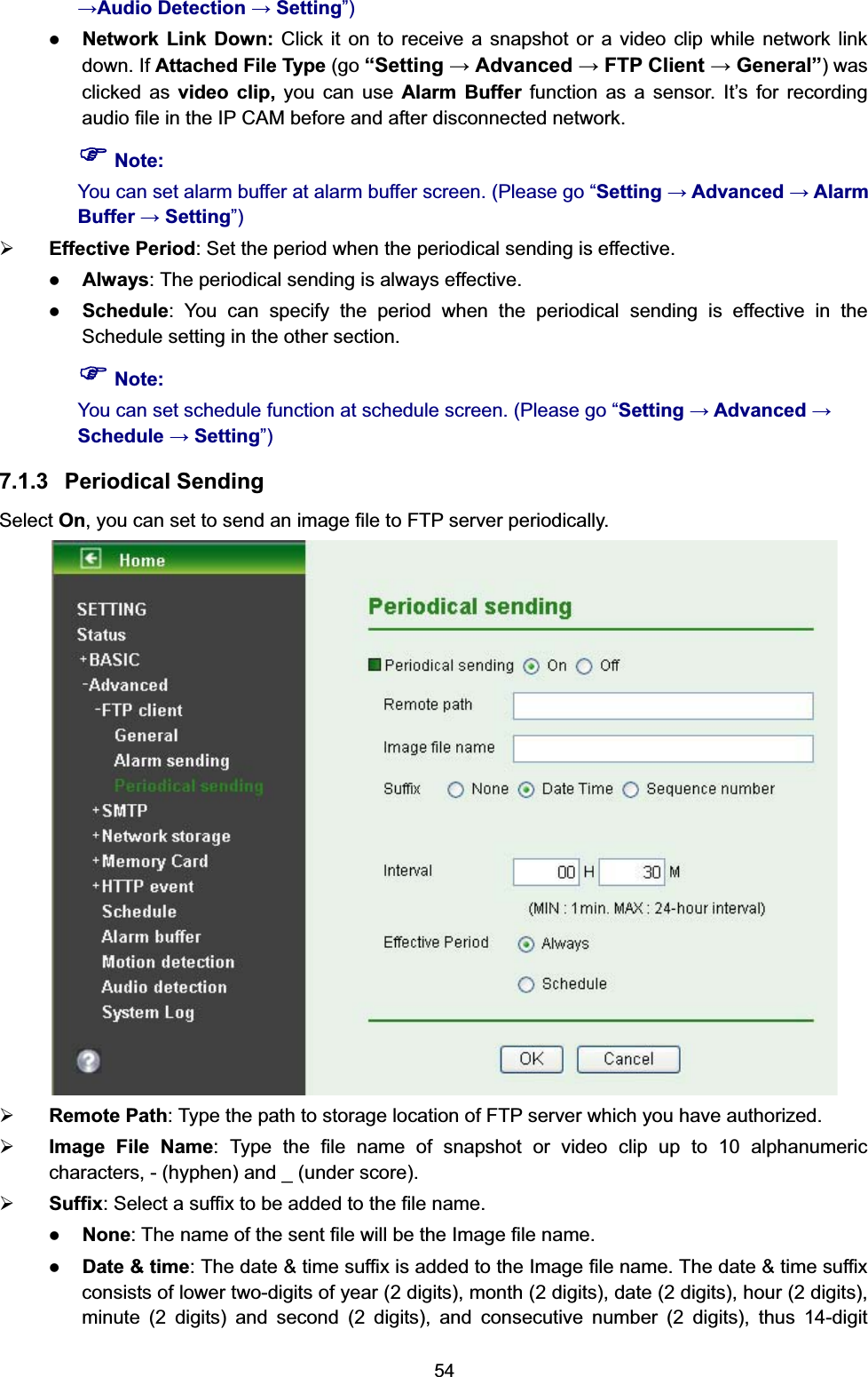
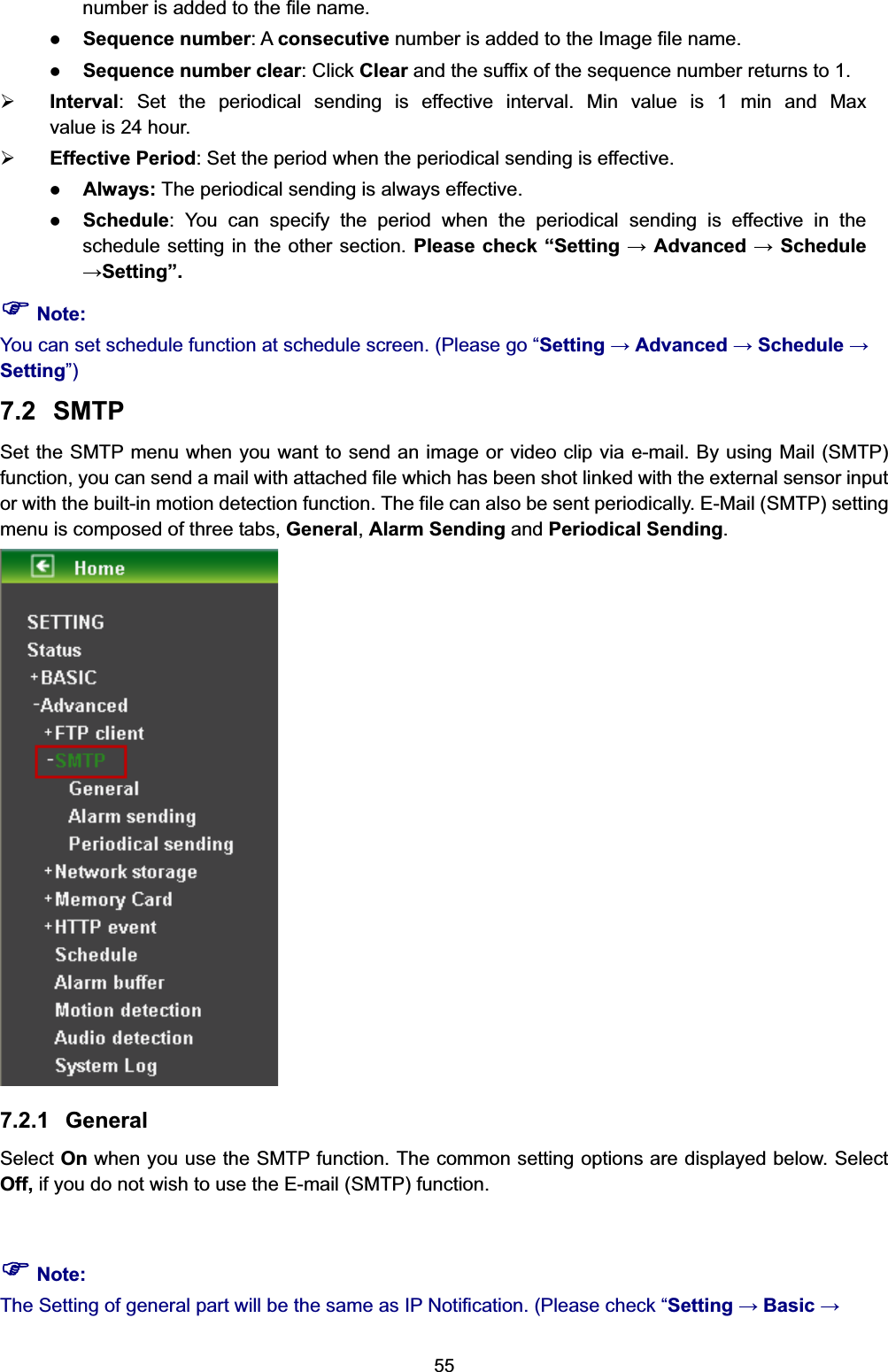
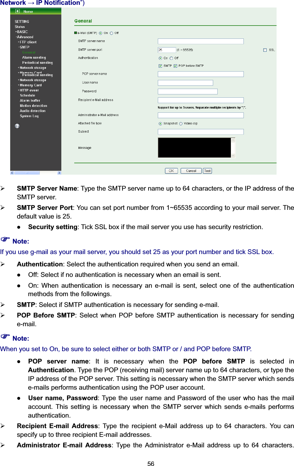
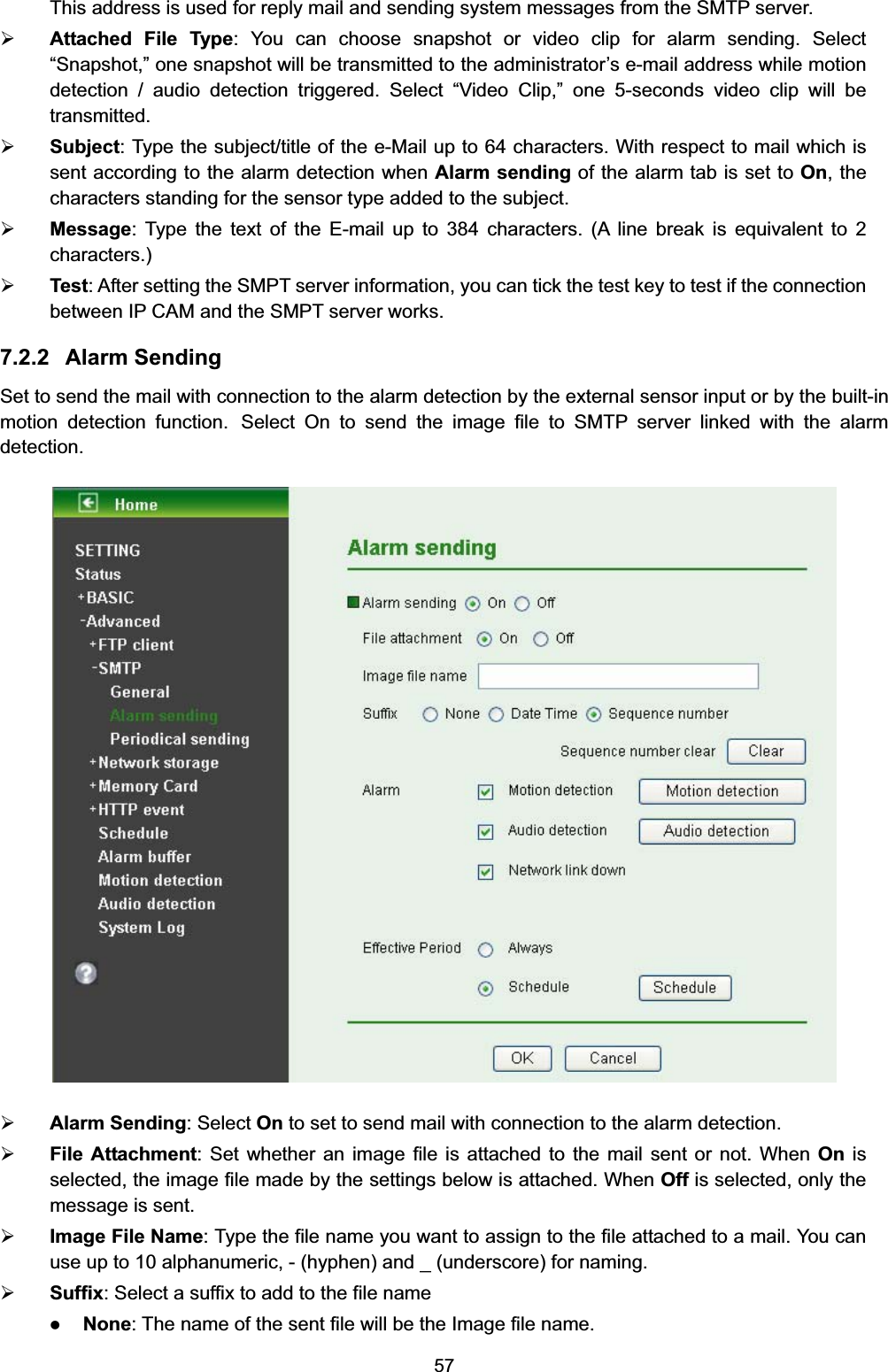
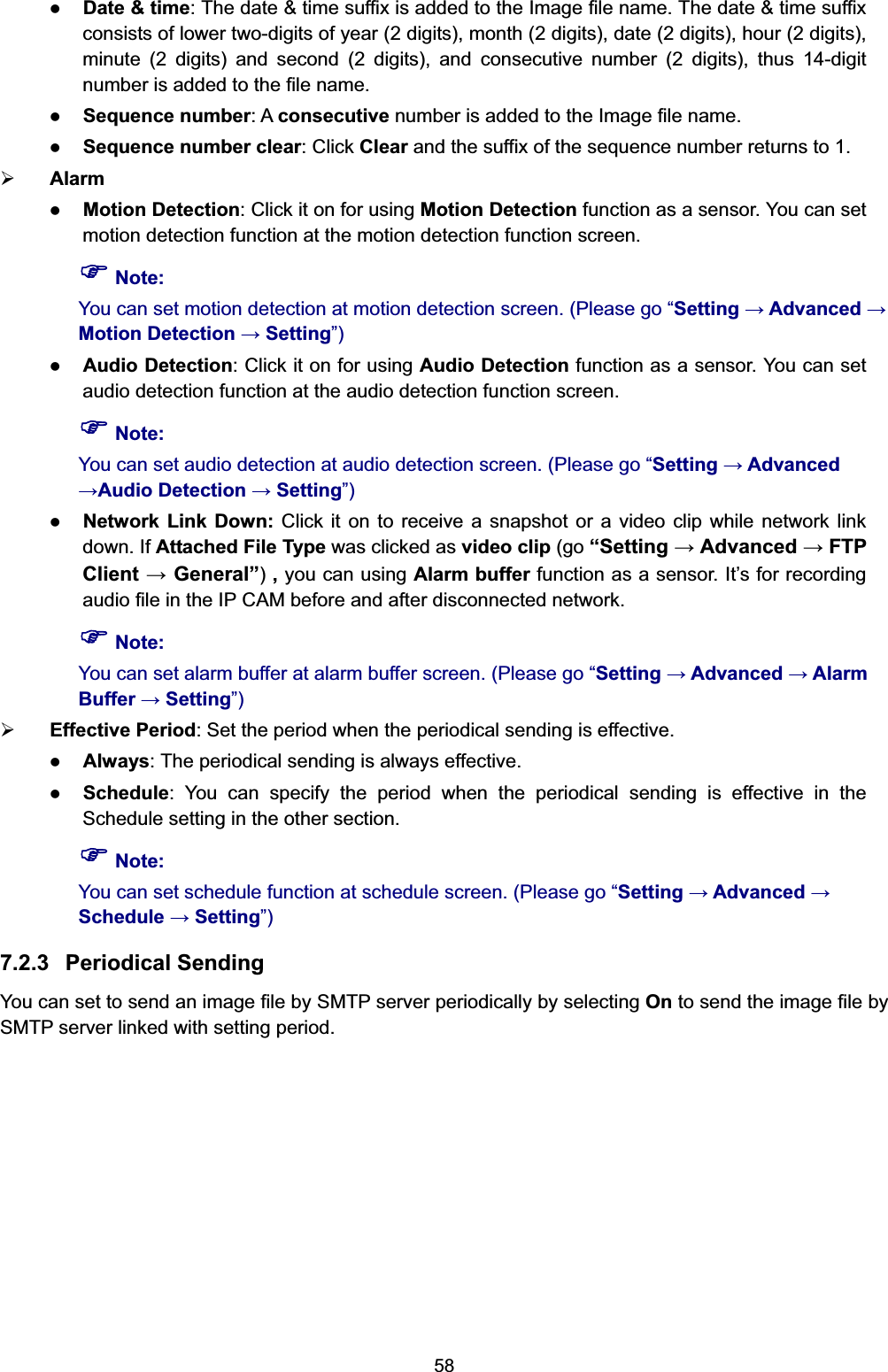
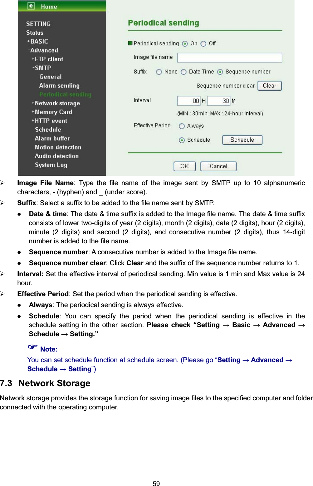
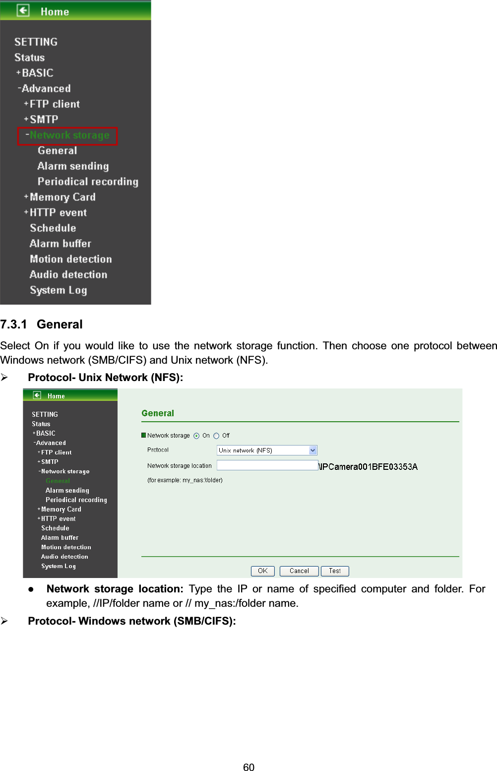
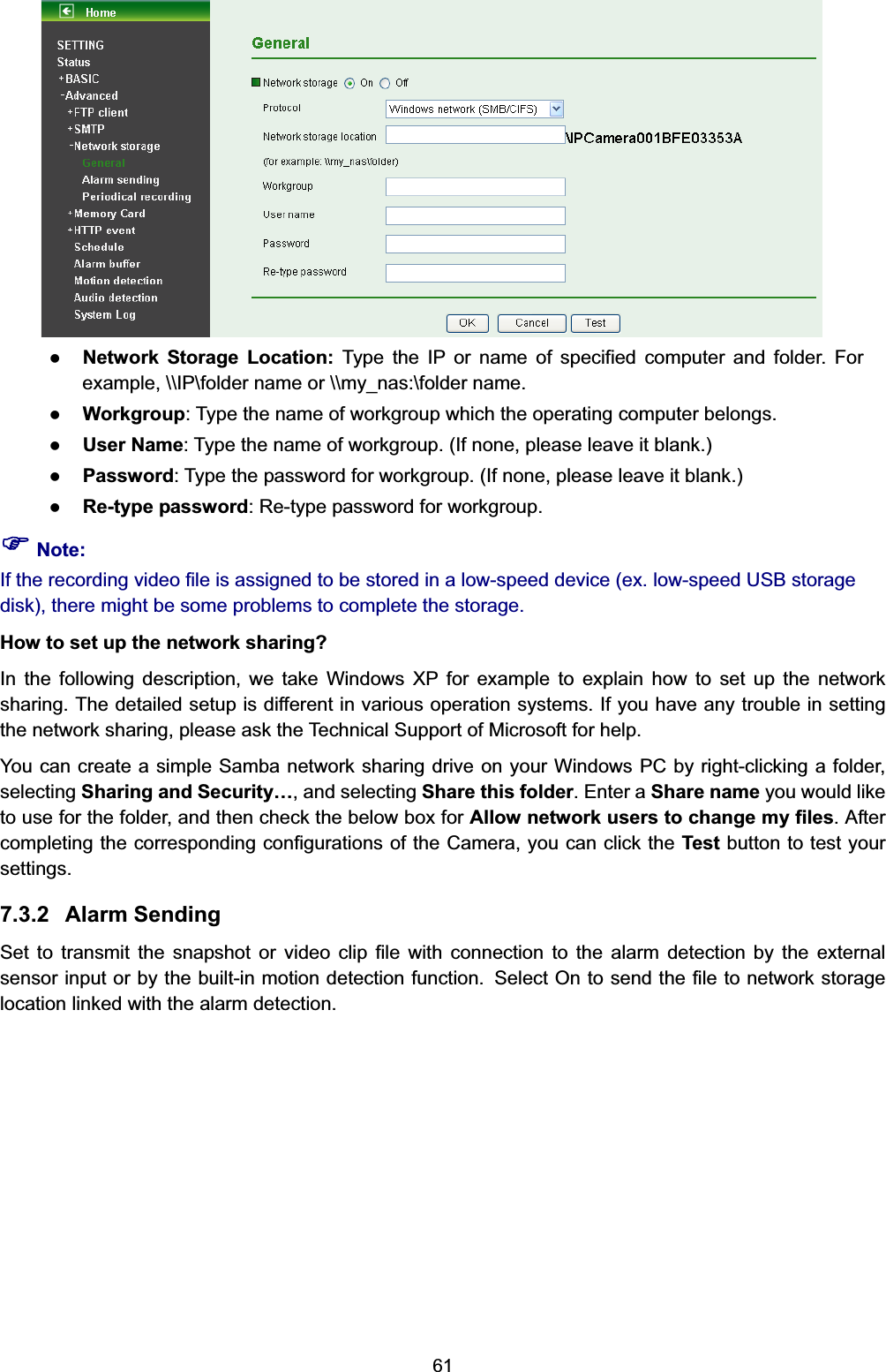
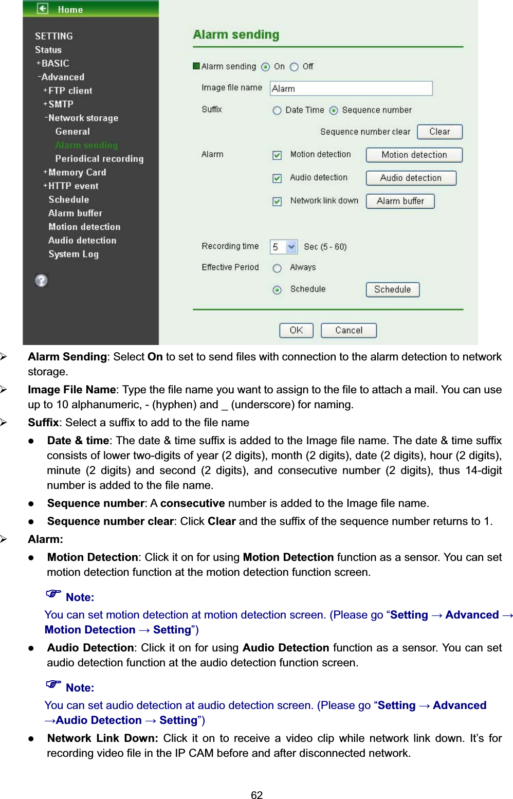
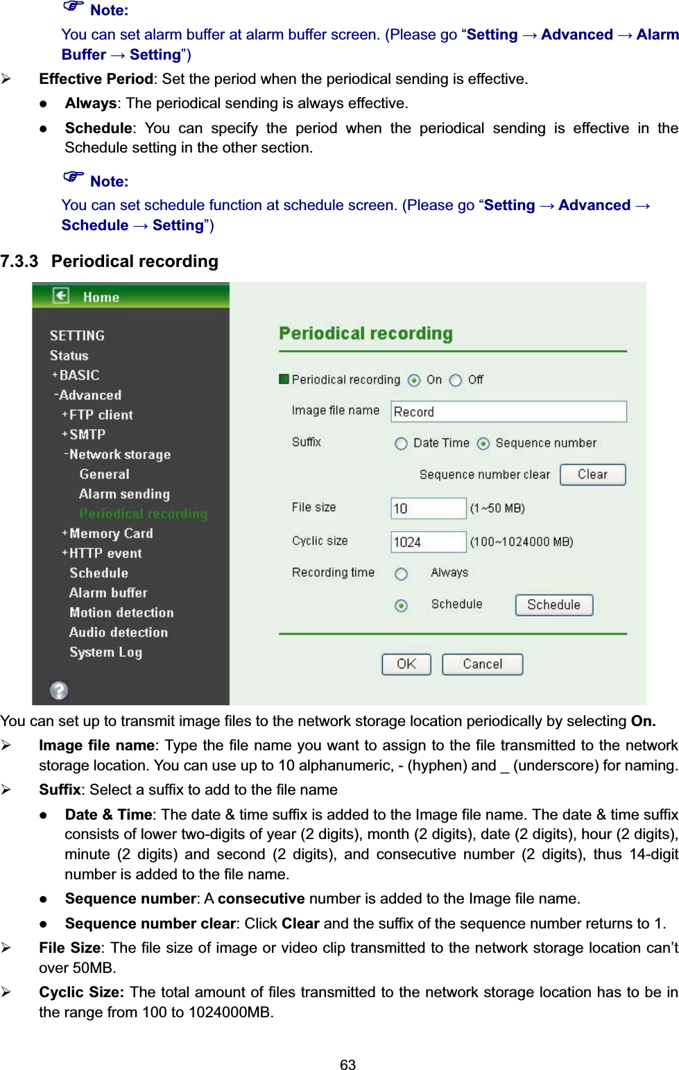
User Manual 2