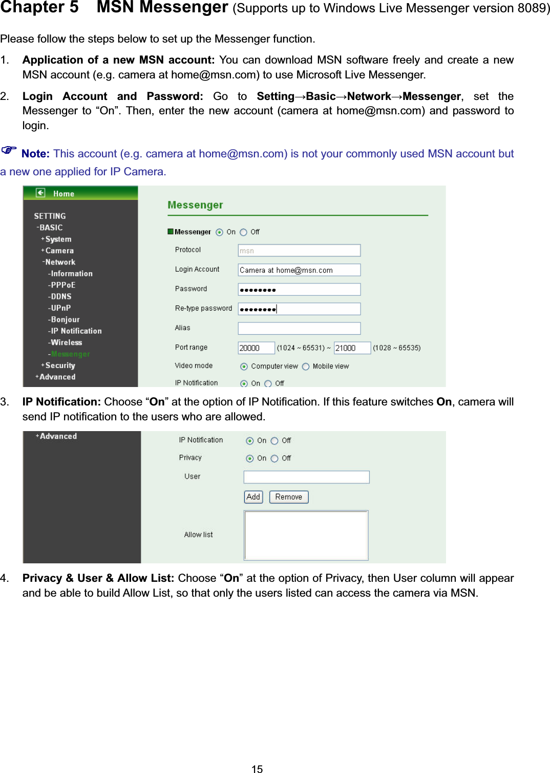
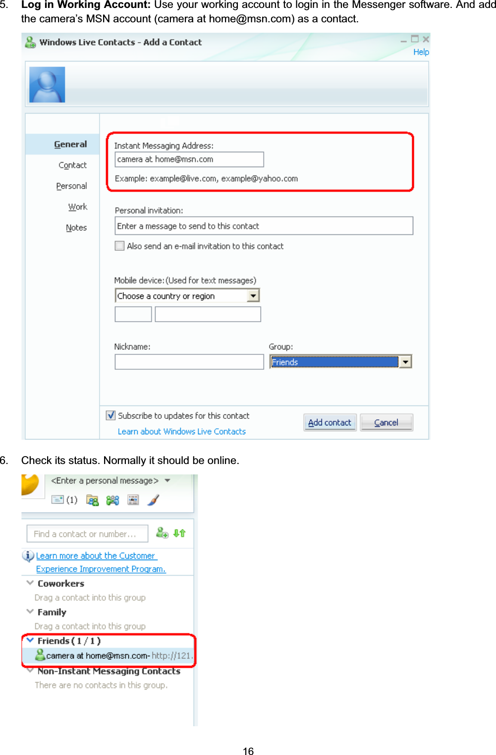
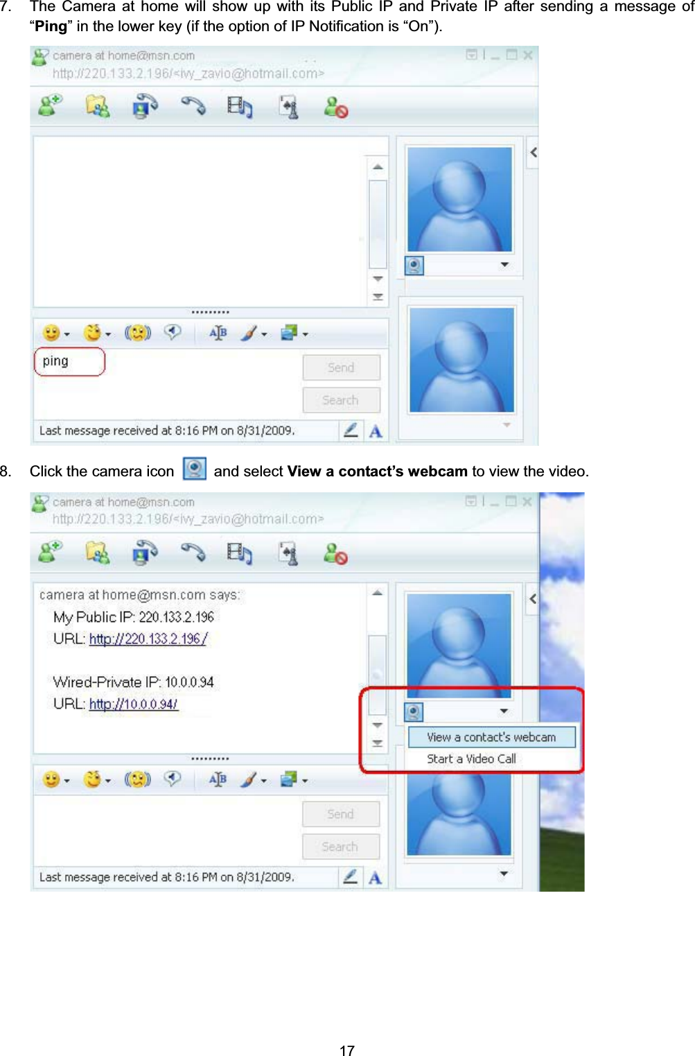
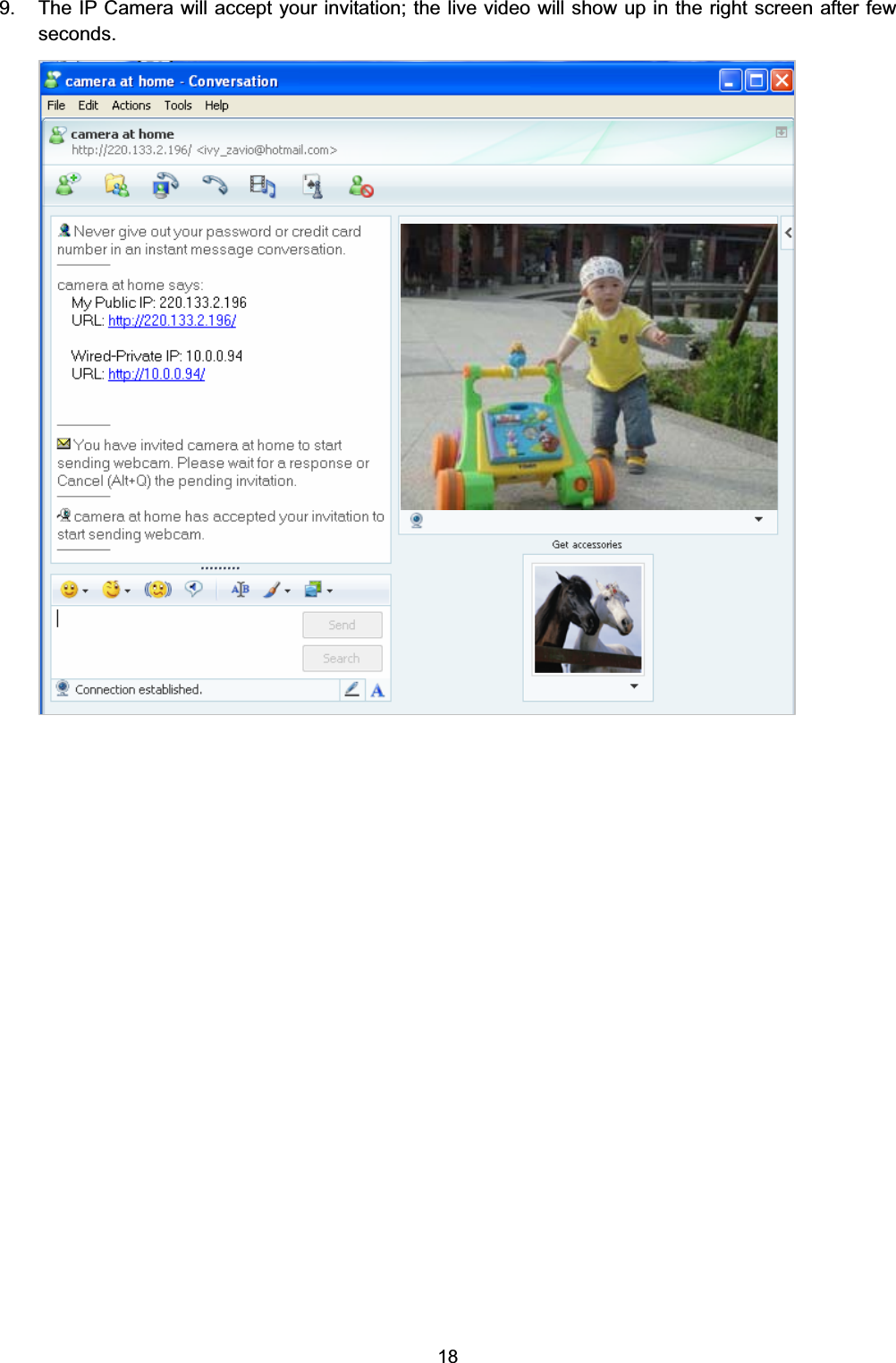
TP Link Technologies SC4171G Wireless Pan/Tilt Surveillance Camera User Manual TL SC4171 1
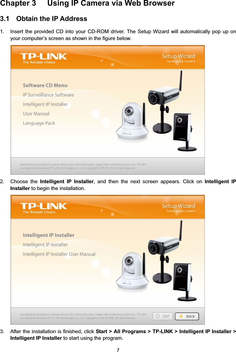
TP-Link Technologies Co., Ltd. Wireless Pan/Tilt Surveillance Camera TL SC4171 1
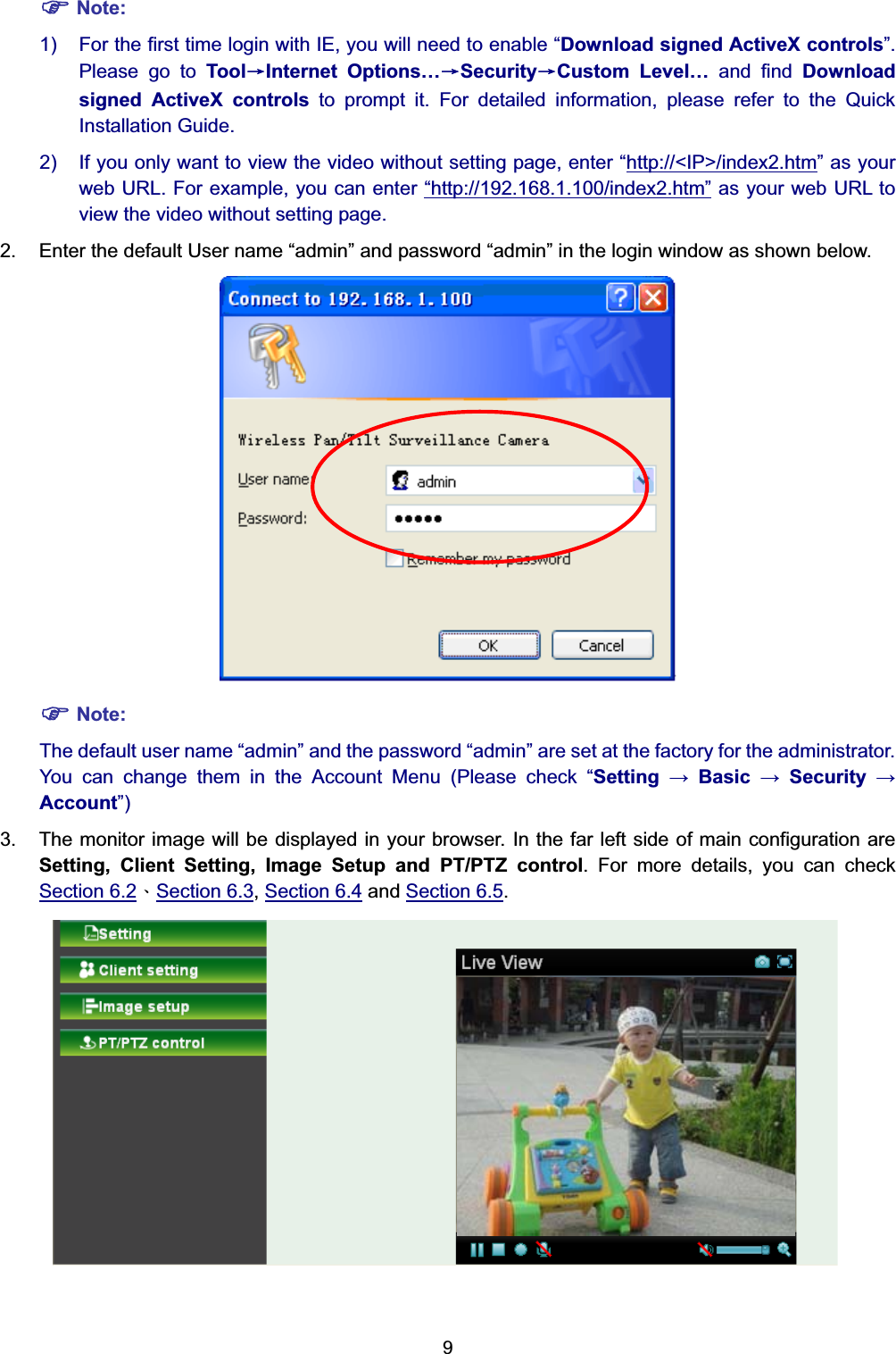
Contents
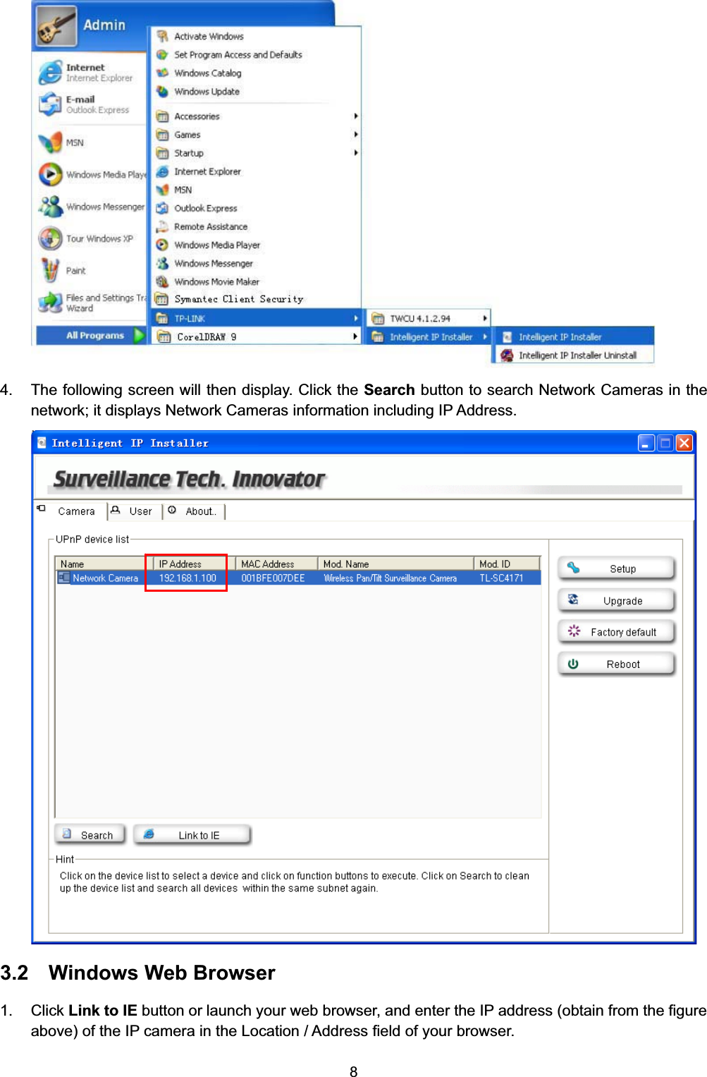
- 1. TL-SC4171_User Manual1
- 2. TL-SC4171_User Manual2
TL-SC4171_User Manual1
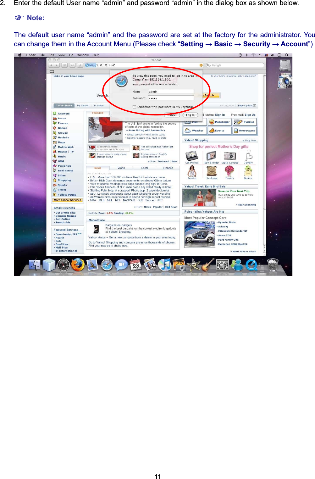
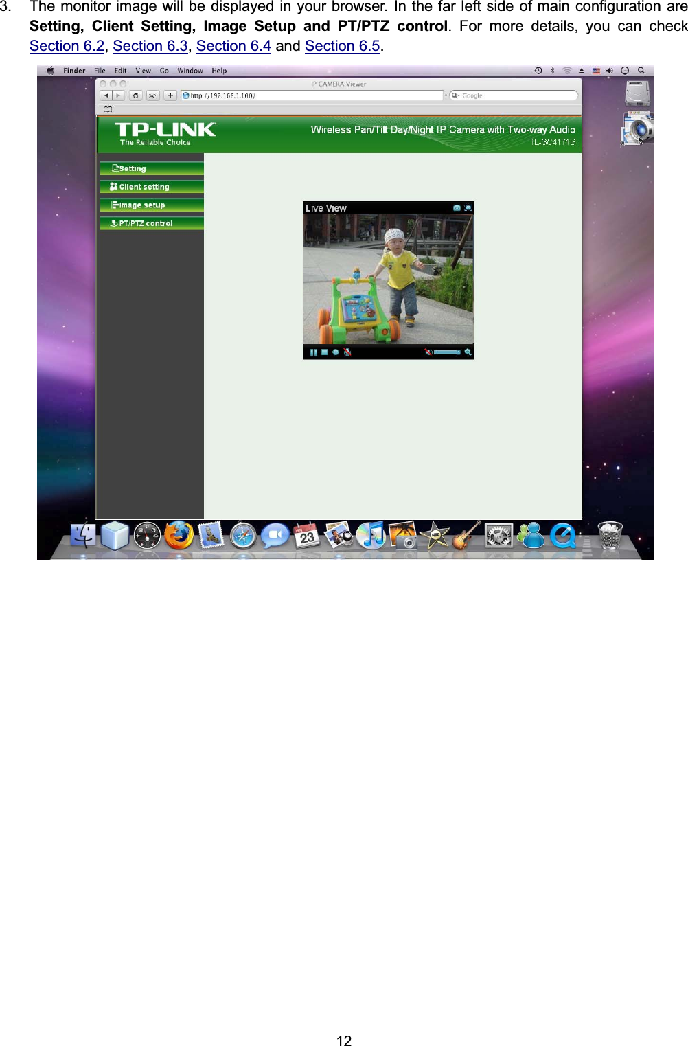
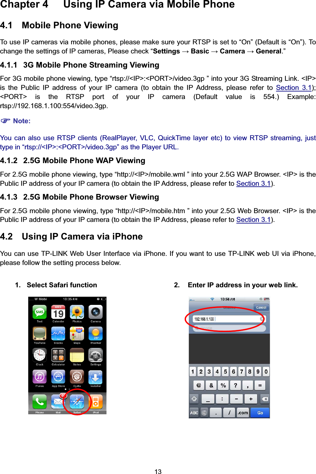
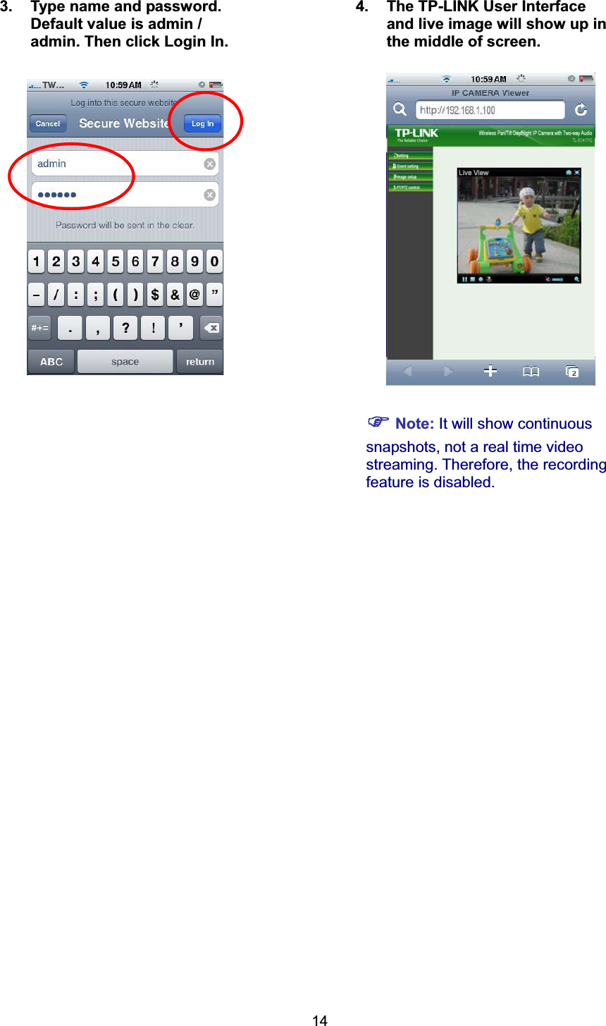
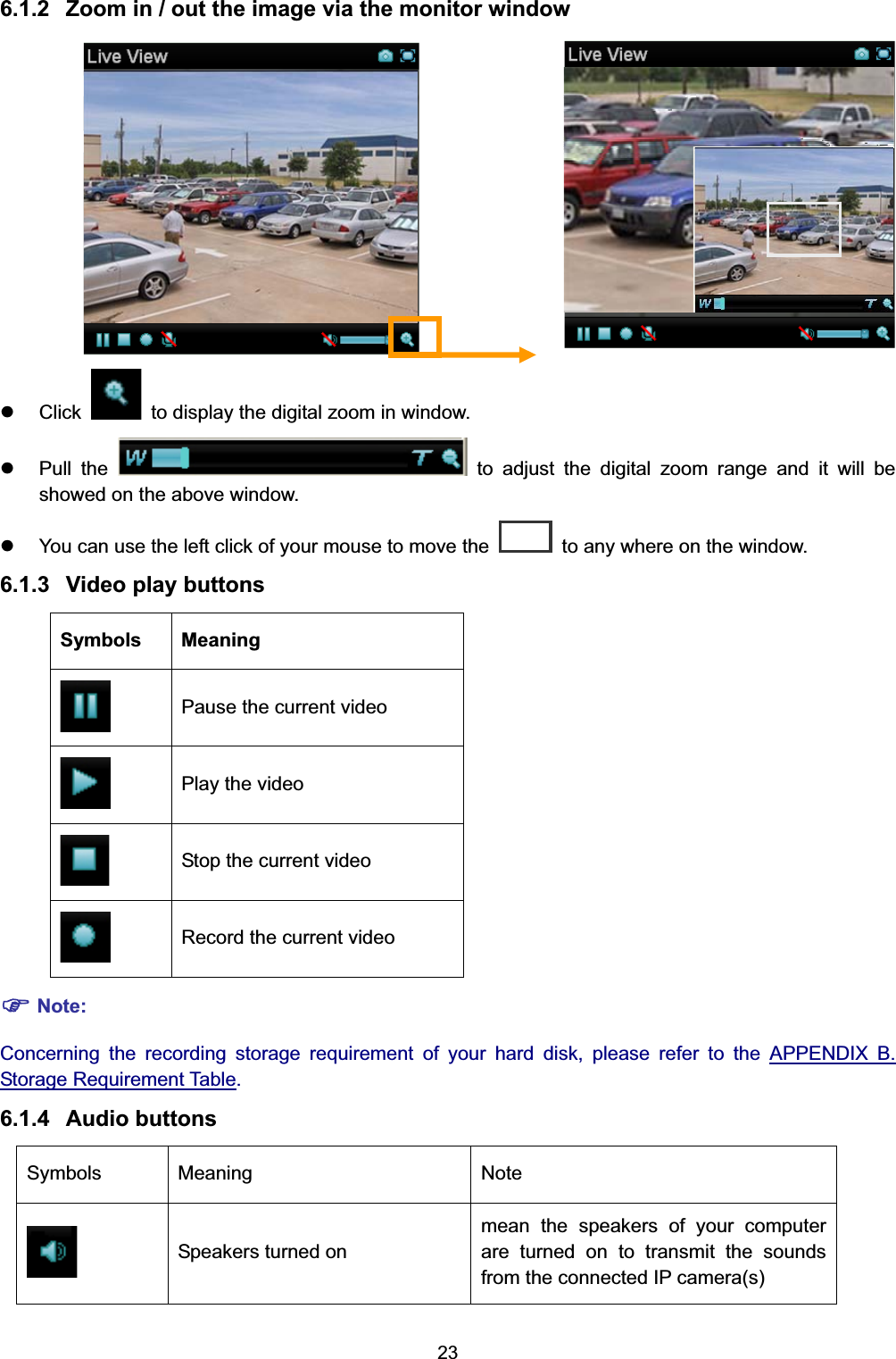
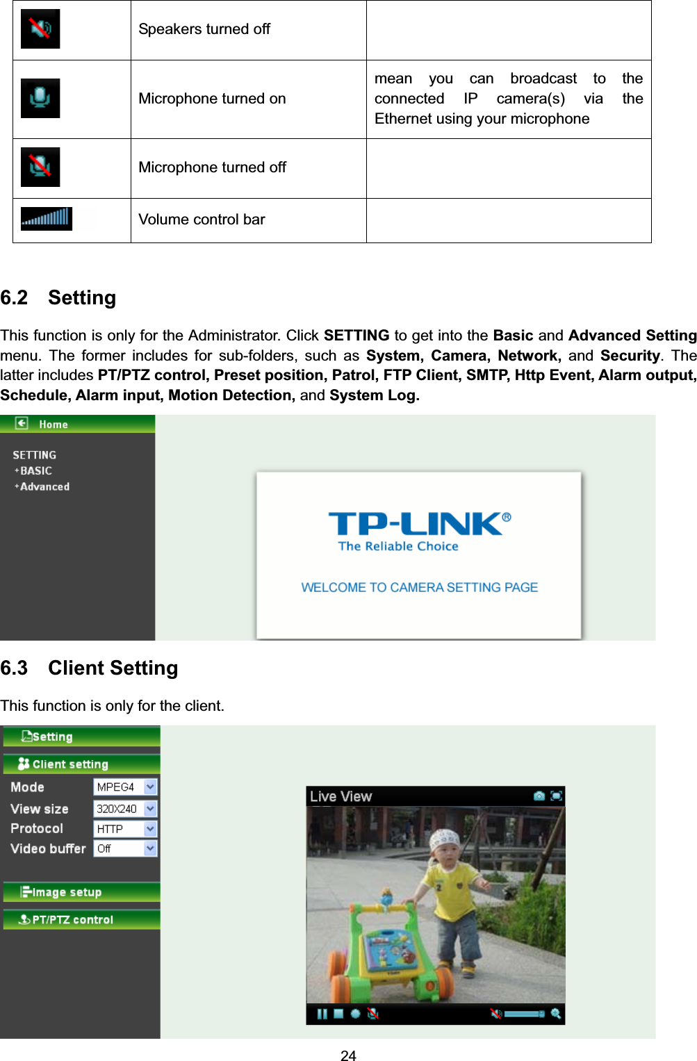
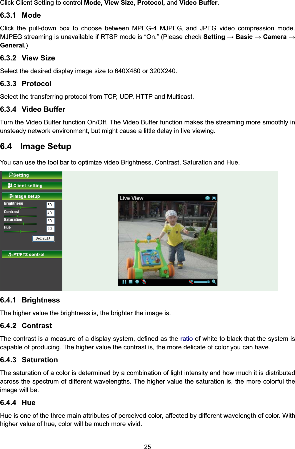
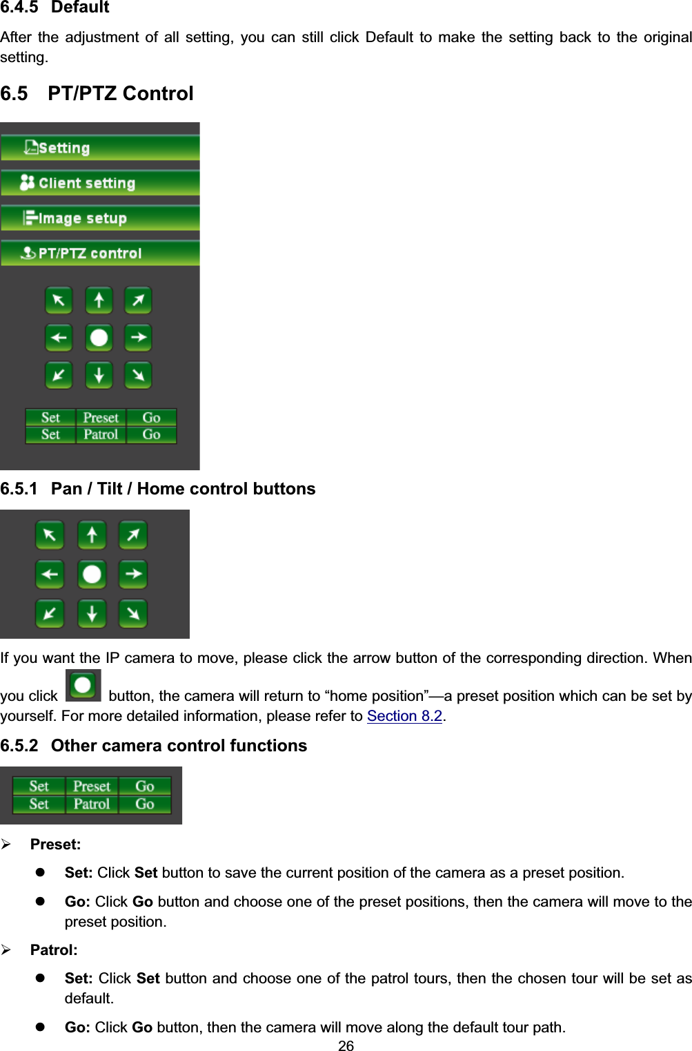
![2 Chapter 1 Safety Instruction ¾ Before you use this product This product has been designed with safety in mind. However, the electrical products can cause fires which may lead to serious body injury if not used properly. To avoid such accidents, be sure to heed the following. ¾ Legal Caution Video and audio surveillance can be forbidden by laws that vary from country to country. Check the laws in your local region before using this product for surveillance purposes. ¾ Don't open the housing of the product Don't try to open the housing or remove the covers which may expose yourself to dangerous voltage or other hazards. ¾ Don't use the accessories not recommended by the manufacturer ¾ Heed the safety precautions Be sure to follow the general safety precautions and the “Operation Notice.” ¾ Operation Notice - Operating or storage location Avoid operating or storing the camera in the following locations: x Extremely hot or cold places (Operating temperature: 0 °C to + 50 °C [32 °F to 122°F] ) x Exposed to direct sunlight for a long time, or close to heating equipment (e.g., near heaters) x Close to water (e.g., near a bathtub, kitchen sink, laundry tub) x Close to sources of strong magnetism x Close to sources of powerful electromagnetic radiation, such as radios or TV transmitters x Locations subject to strong vibration or shock ¾ In case of a breakdown In case of system breakdown, discontinue use and contact your authorized dealer. ¾ In case of abnormal operation x If the unit emits smoke or an unusual smell, x If water or other foreign objects enter the cabinet, or x If you drop the unit or damage the cabinet: 1 Disconnect the cable and the connecting cables. 2 Contact your authorized dealer or the store where you purchased the product. ¾ Transportation When transporting the camera, repack it as originally packed at the factory or in materials of equal quality. ¾ Ventilation To prevent heat buildup, do not block air circulation around the device. ¾ Cleaning x Use a soft, dry cloth to clean the external surfaces of the device. Stubborn stains can be removed using a soft cloth dampened with a small quantity of detergent solution, then wipe dry. x Do not use volatile solvents such as alcohol, benzene or thinners as they may damage the surface.](https://usermanual.wiki/TP-Link-Technologies/SC4171G.TL-SC4171-User-Manual1/User-Guide-1568578-Page-7.png)