TP Link Technologies TD851W 150Mbps Wireless N ADSL2+ Modem Router User Manual TD851W User Guide
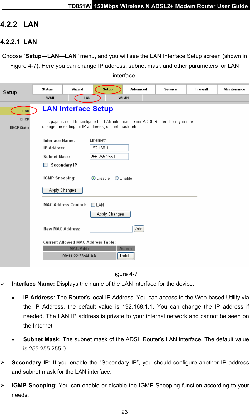
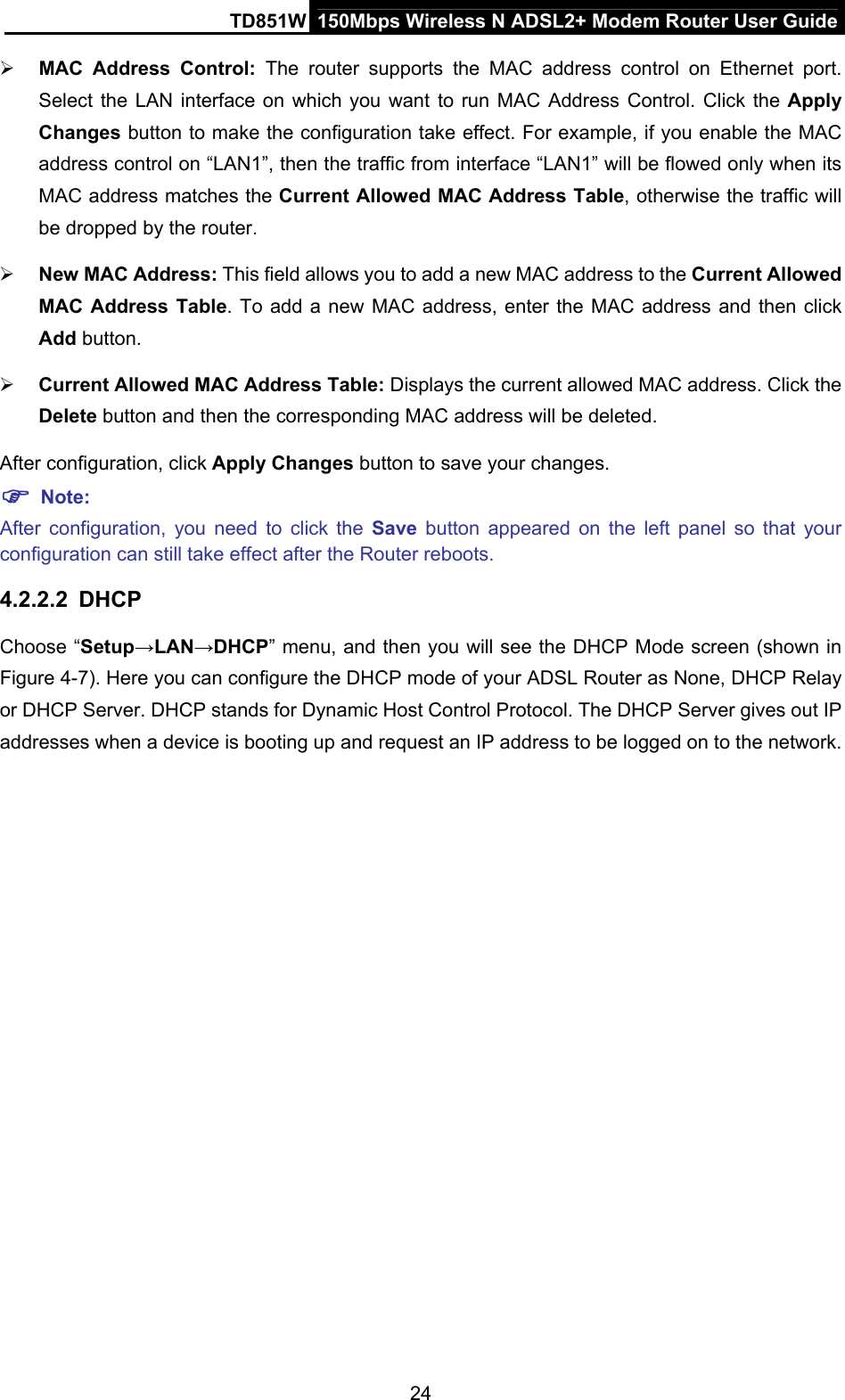
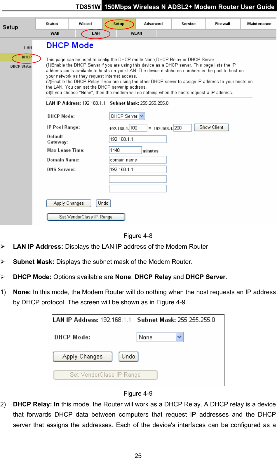
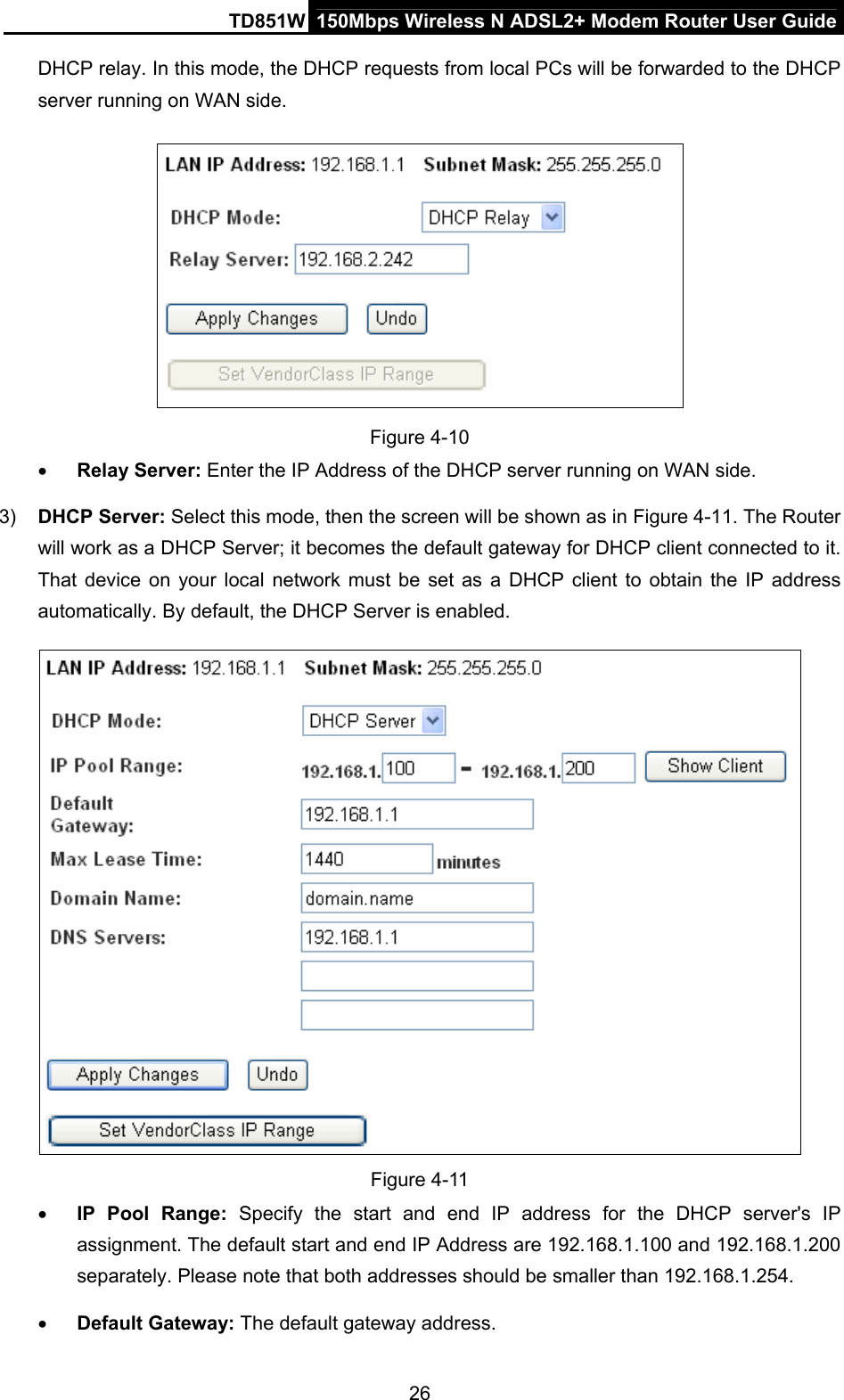
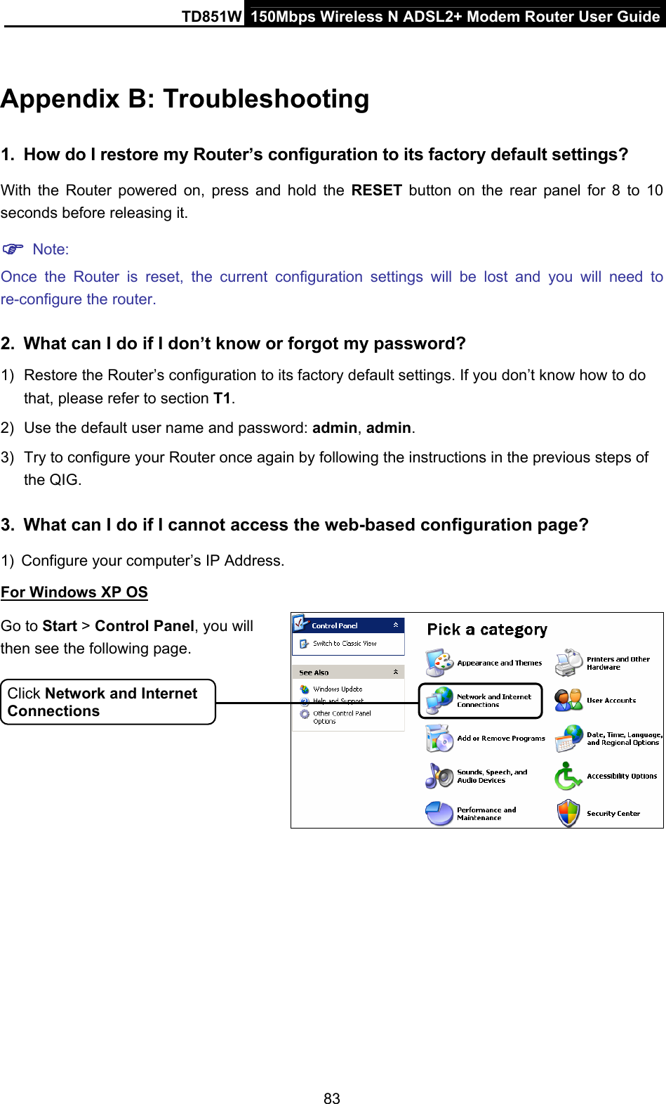
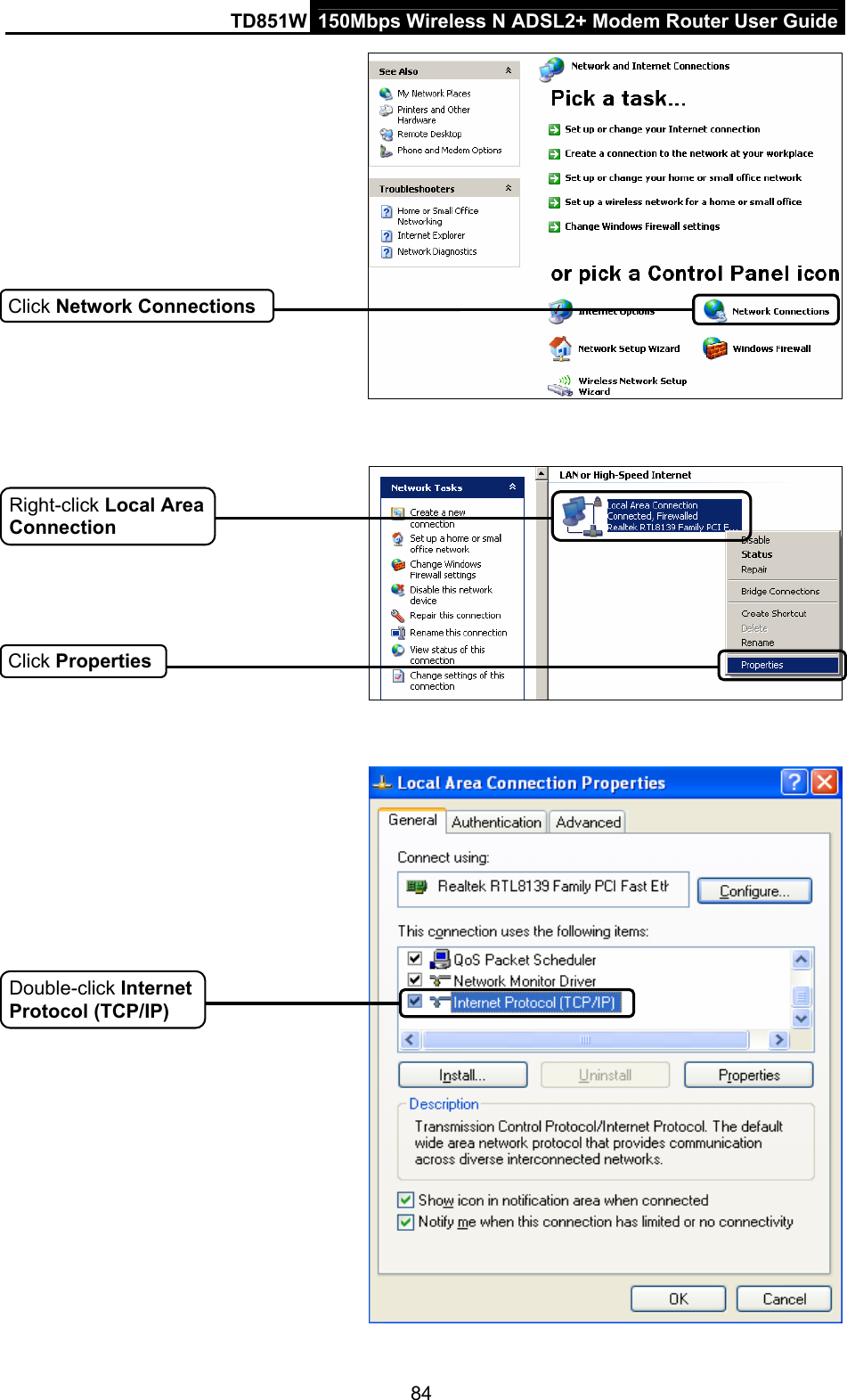
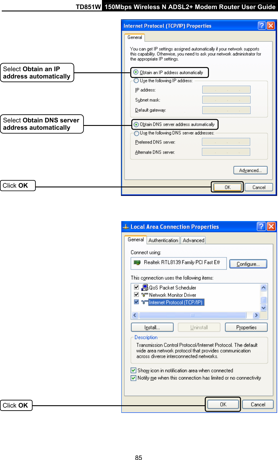
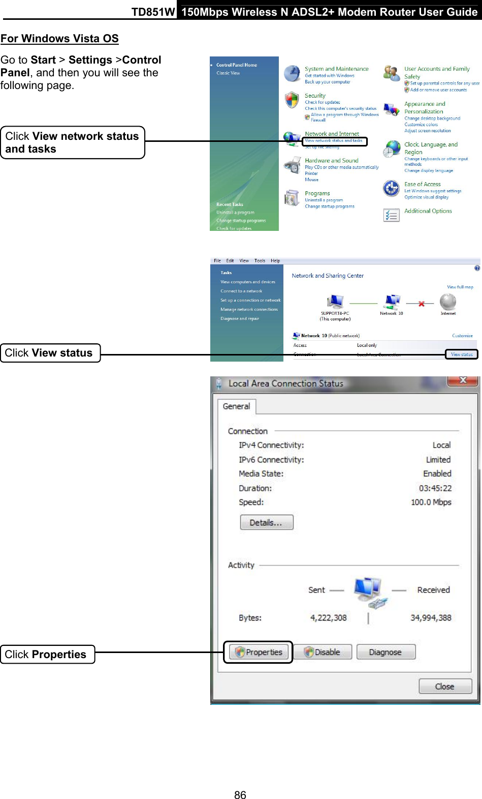
TP-Link Technologies Co., Ltd. 150Mbps Wireless N ADSL2+ Modem Router TD851W User Guide
UserManual.wiki
>
TP Link Technologies
>
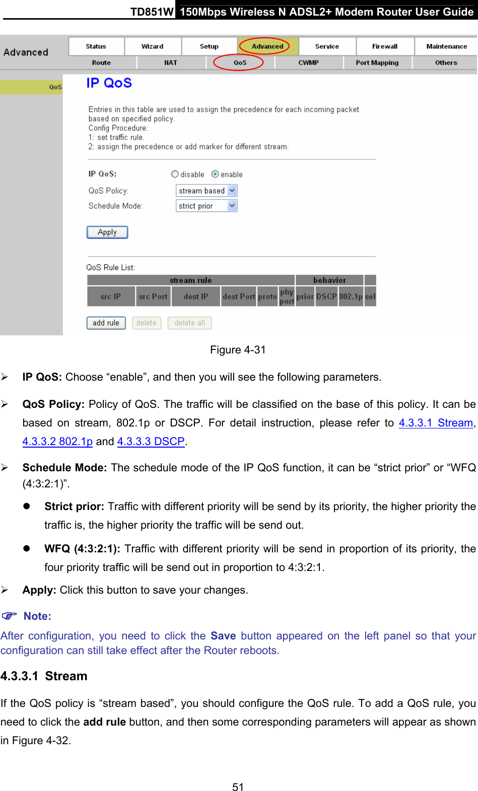
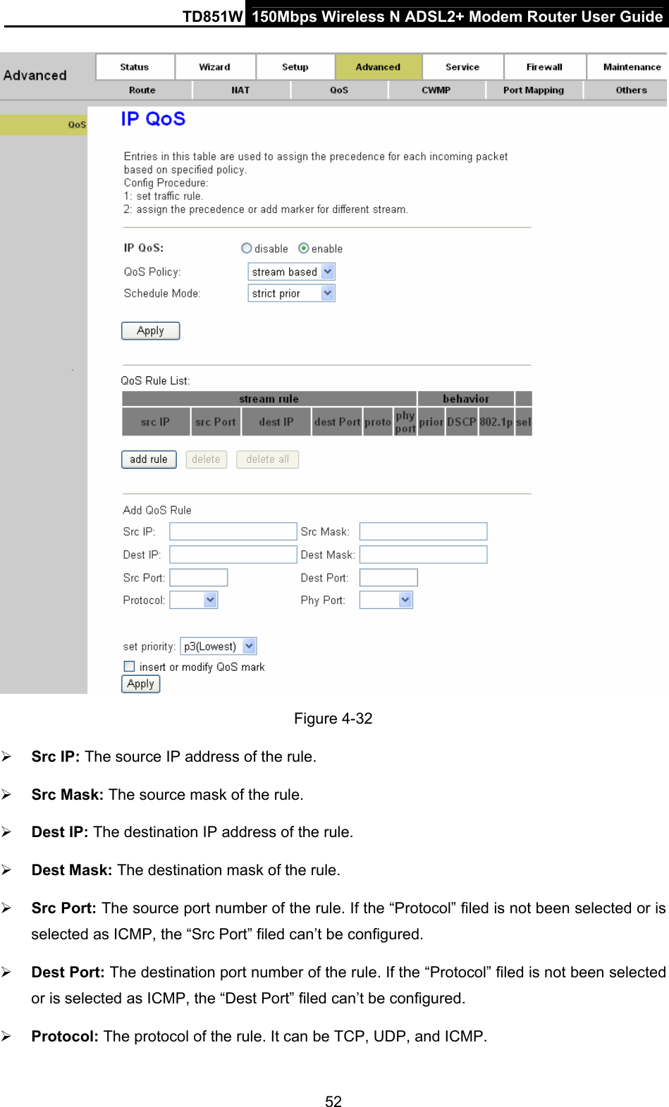
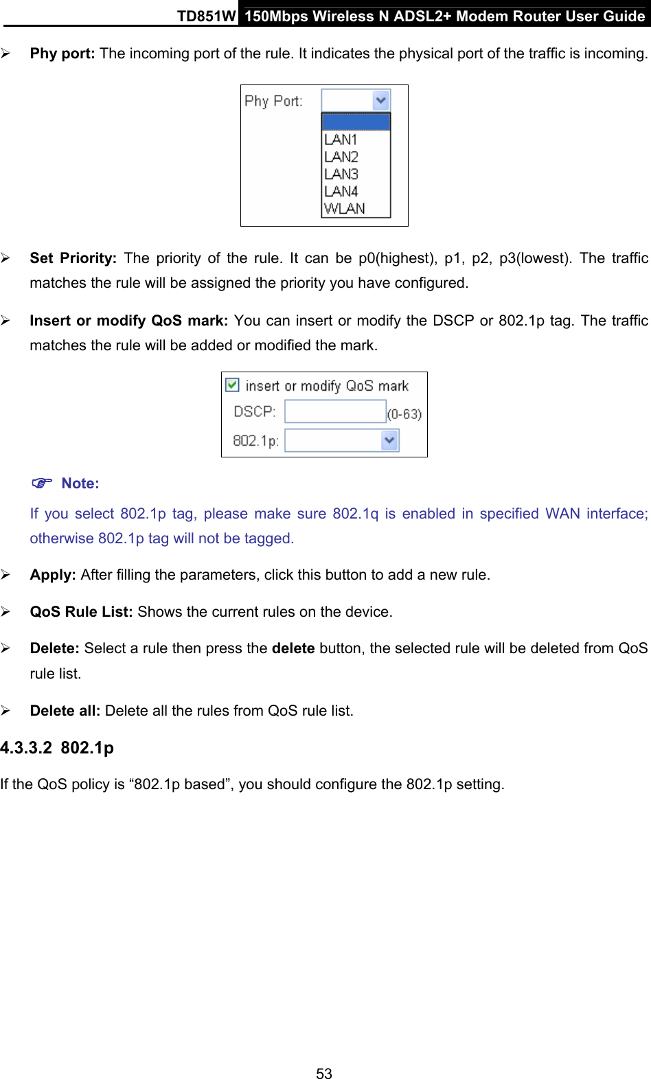
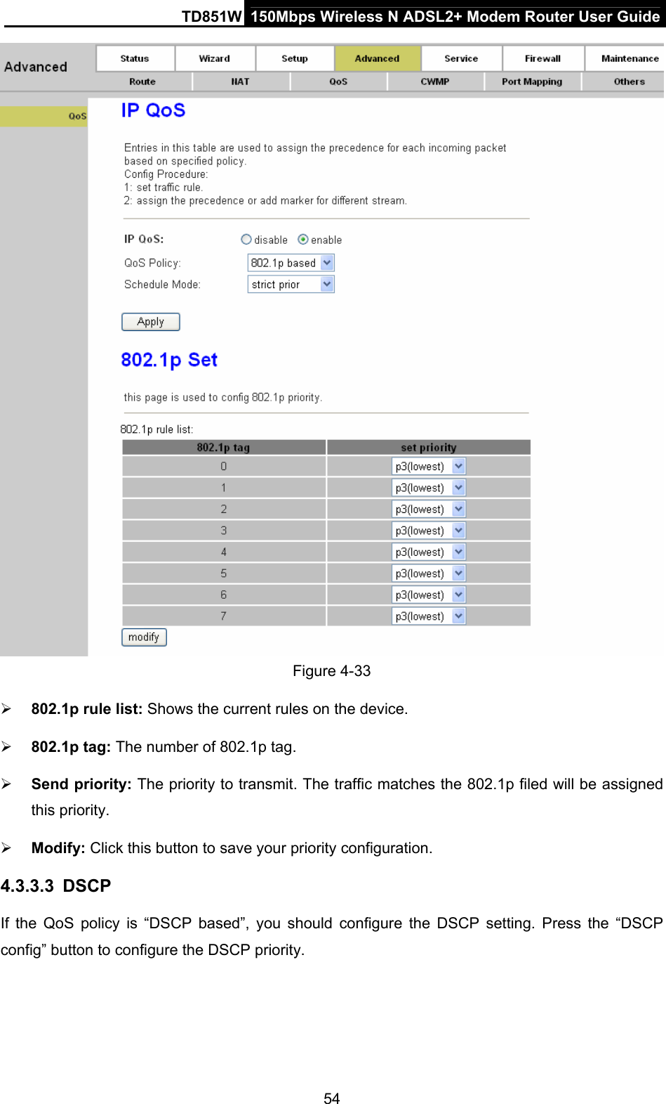
TD851W User Manual
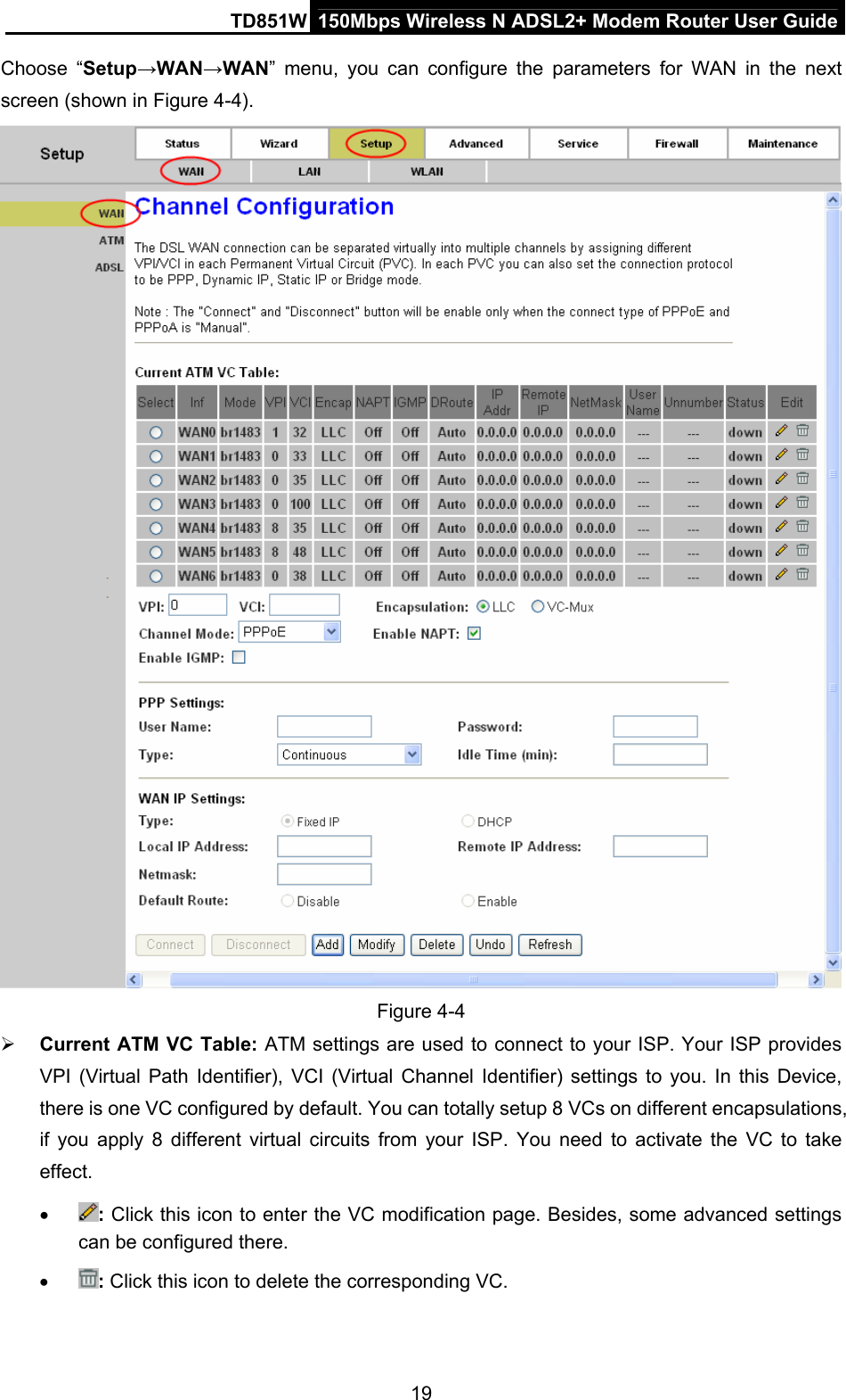
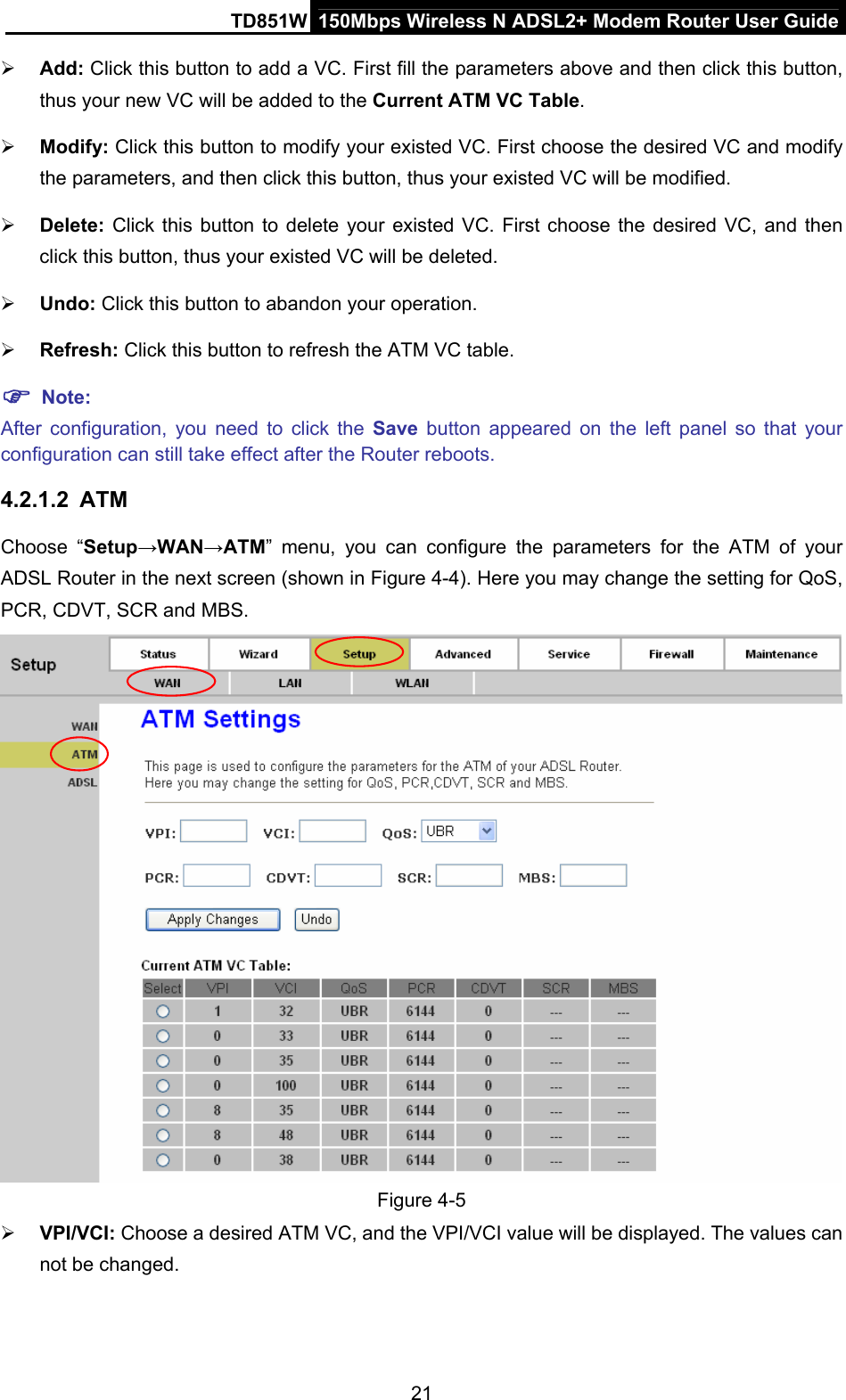
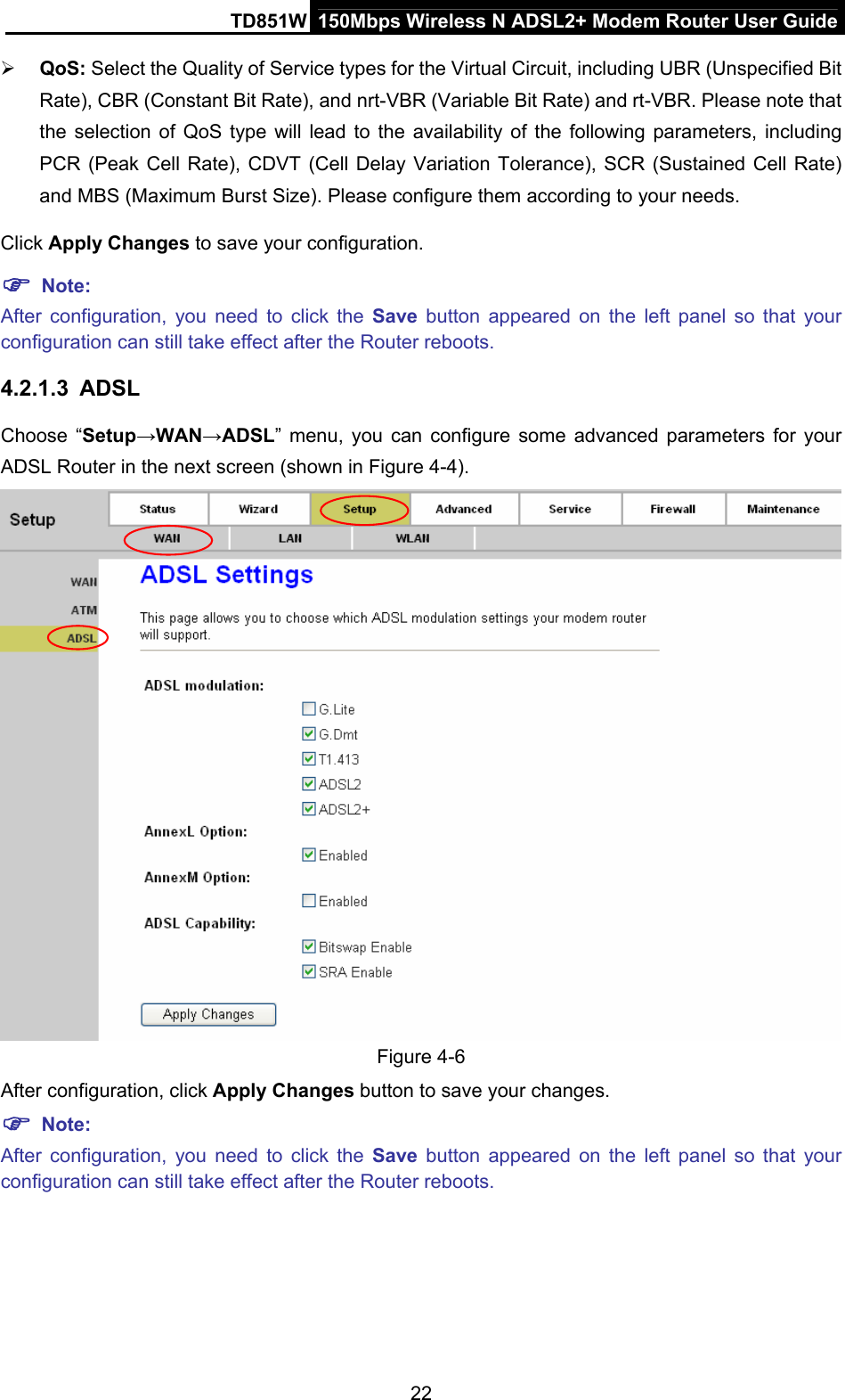
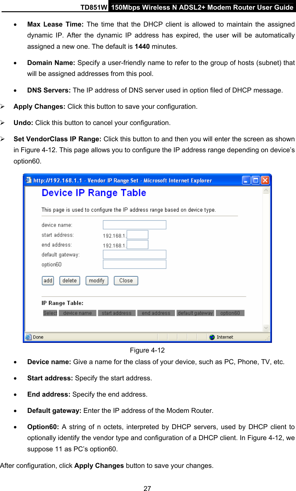
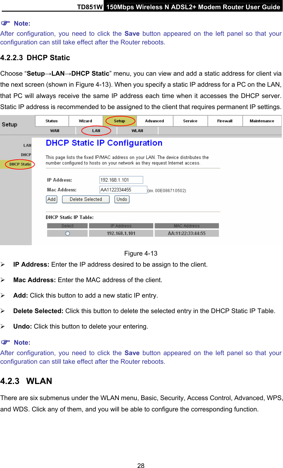
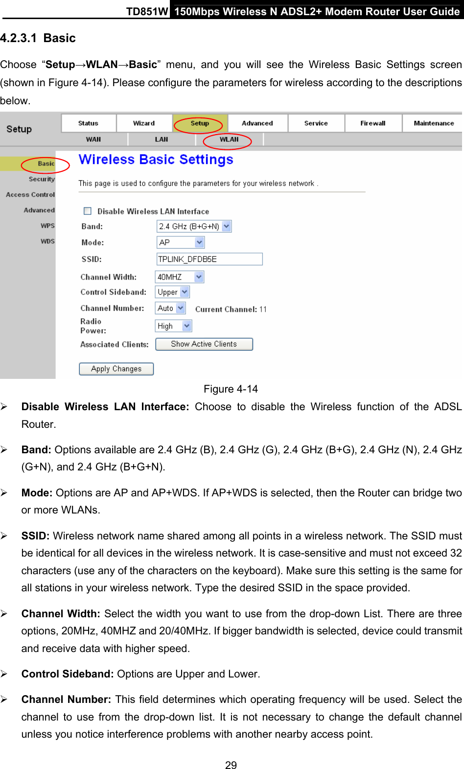
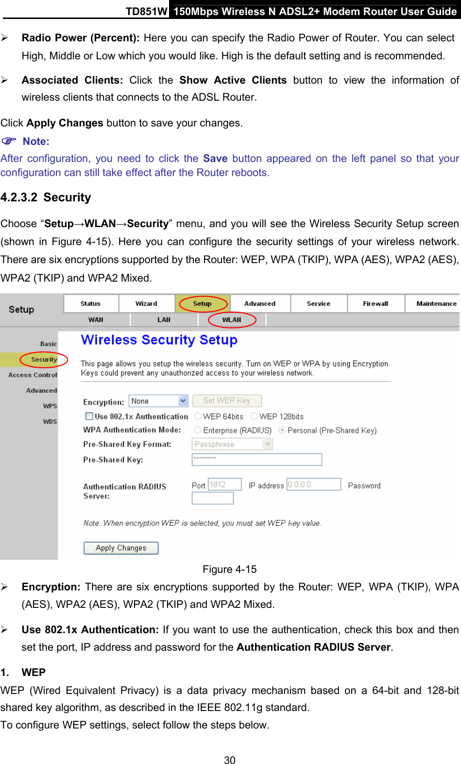
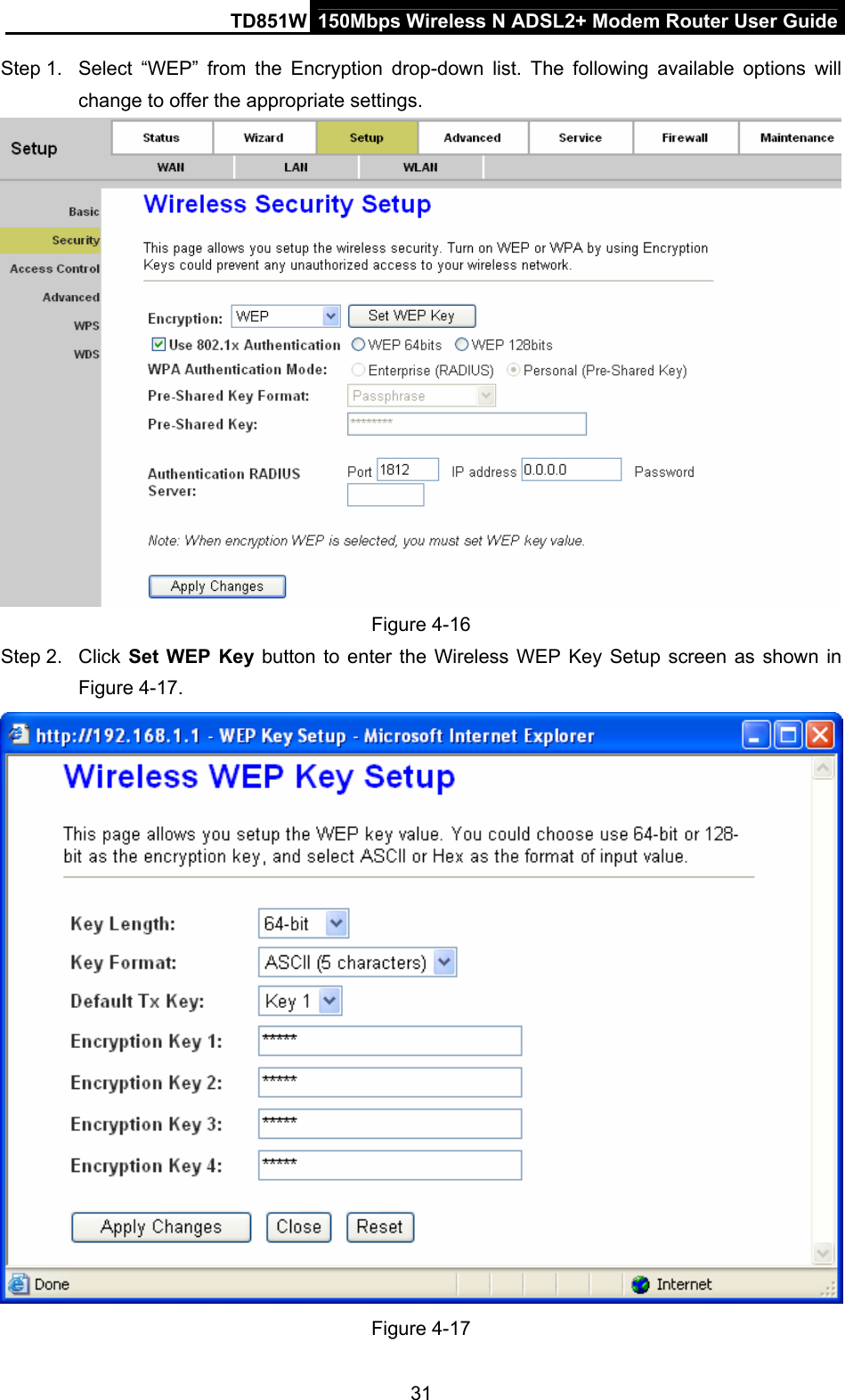
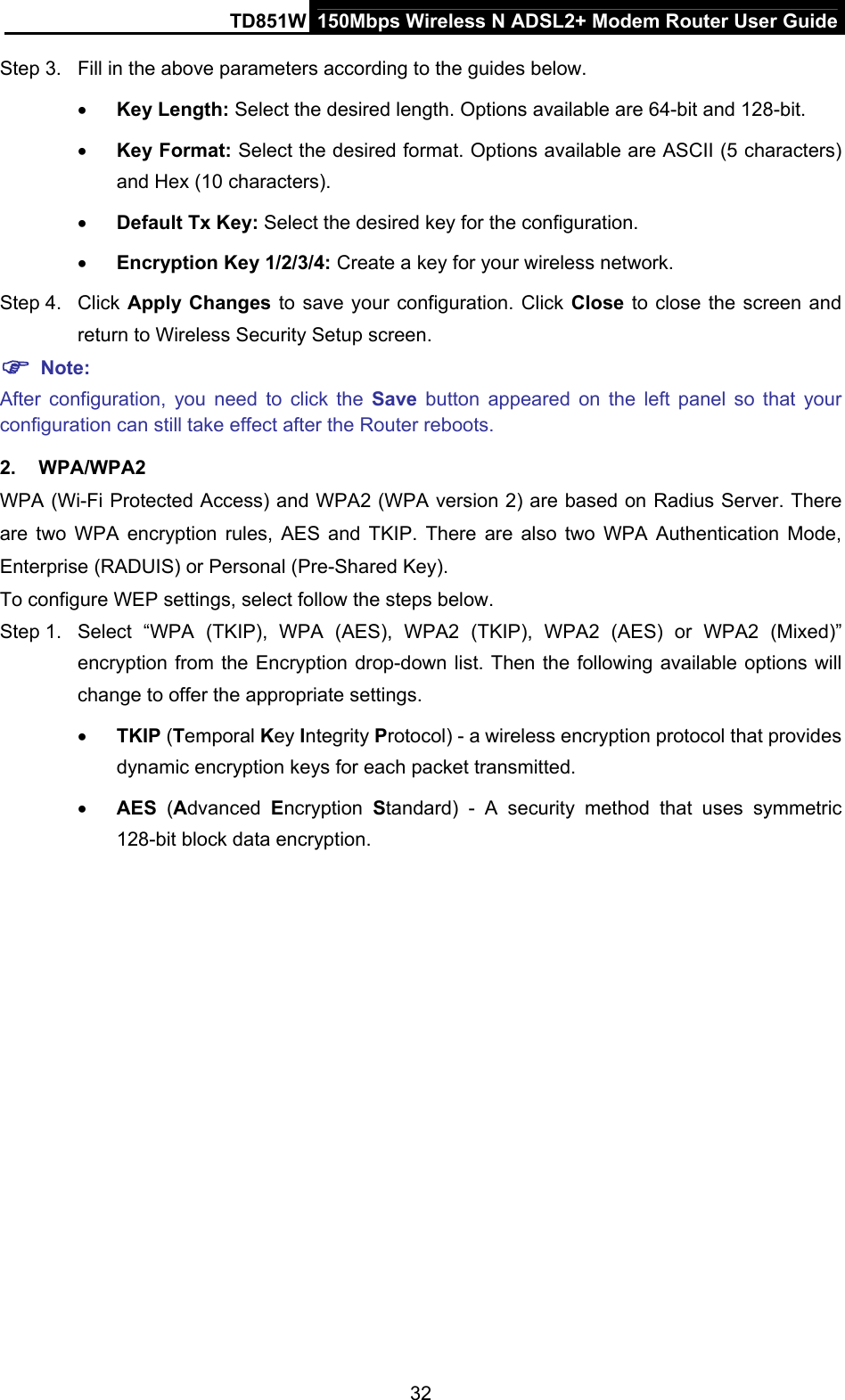
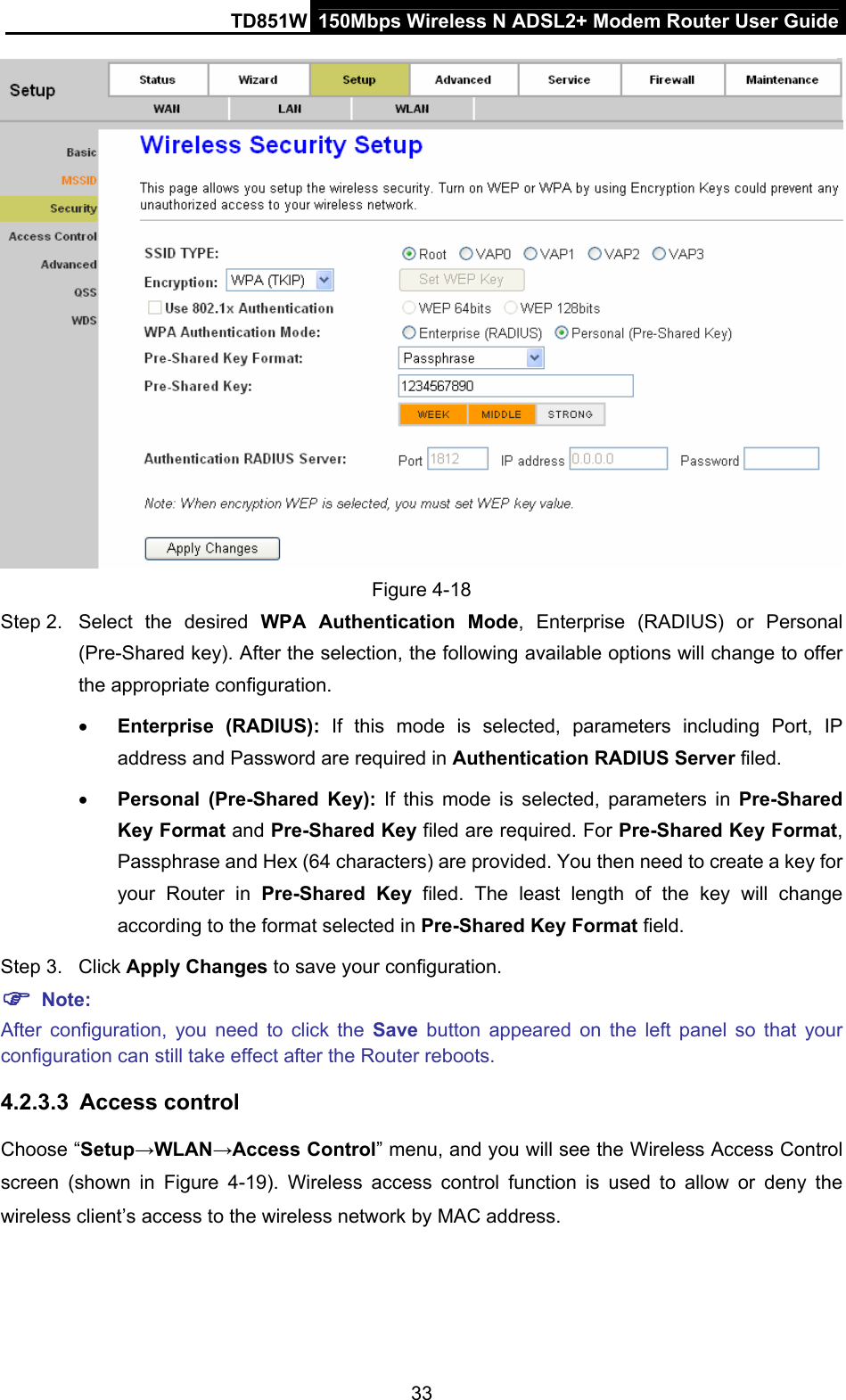
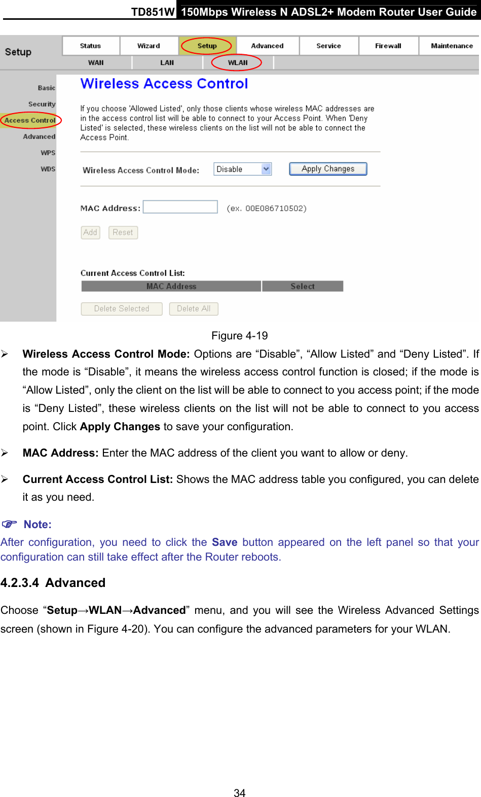
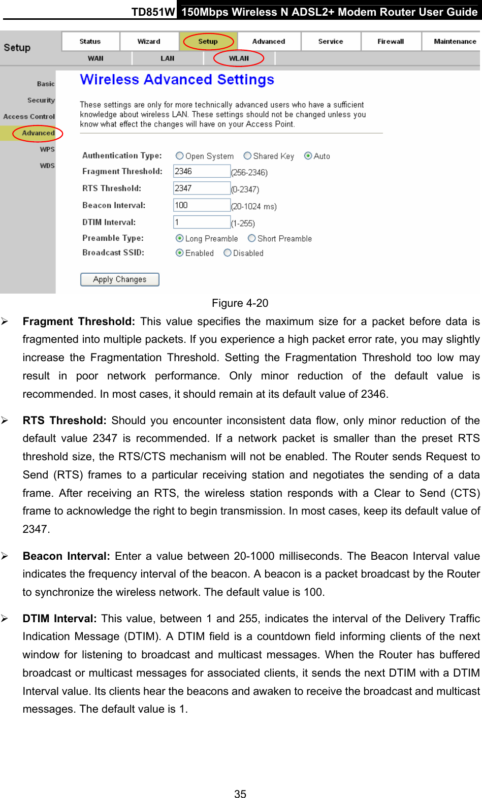
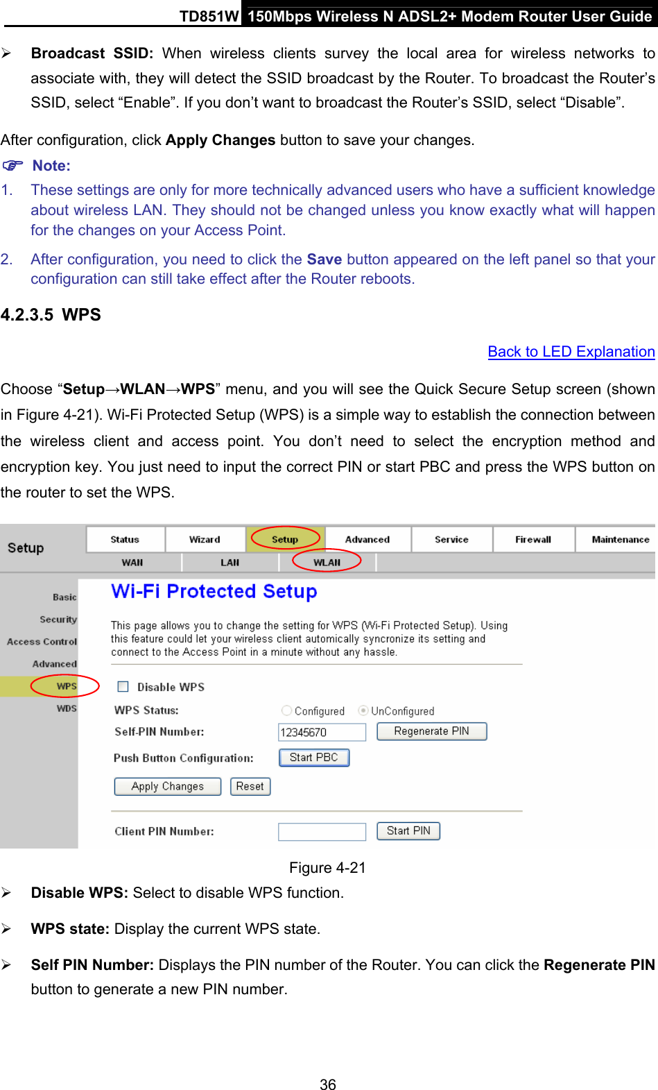
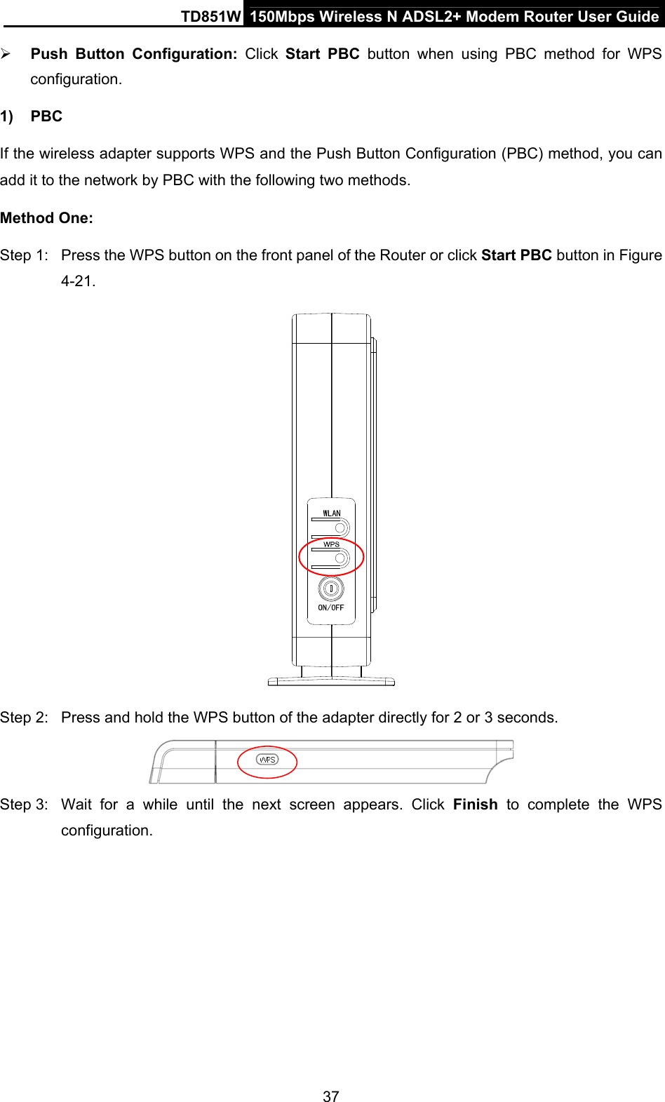
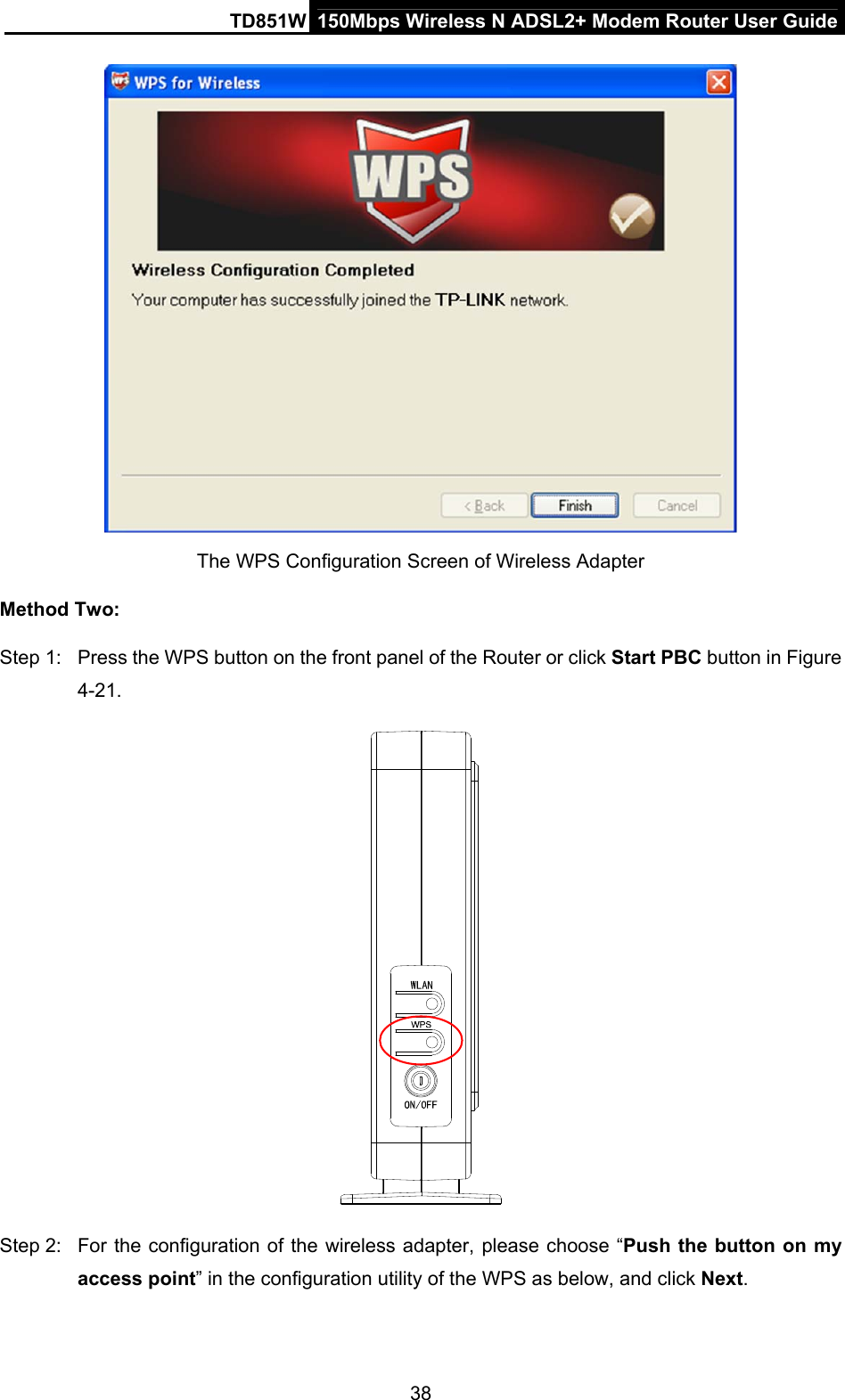
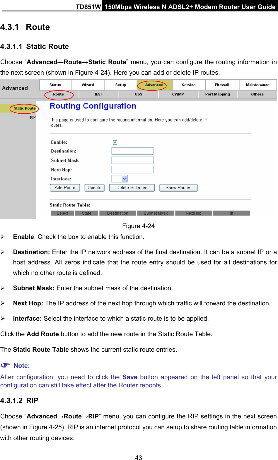
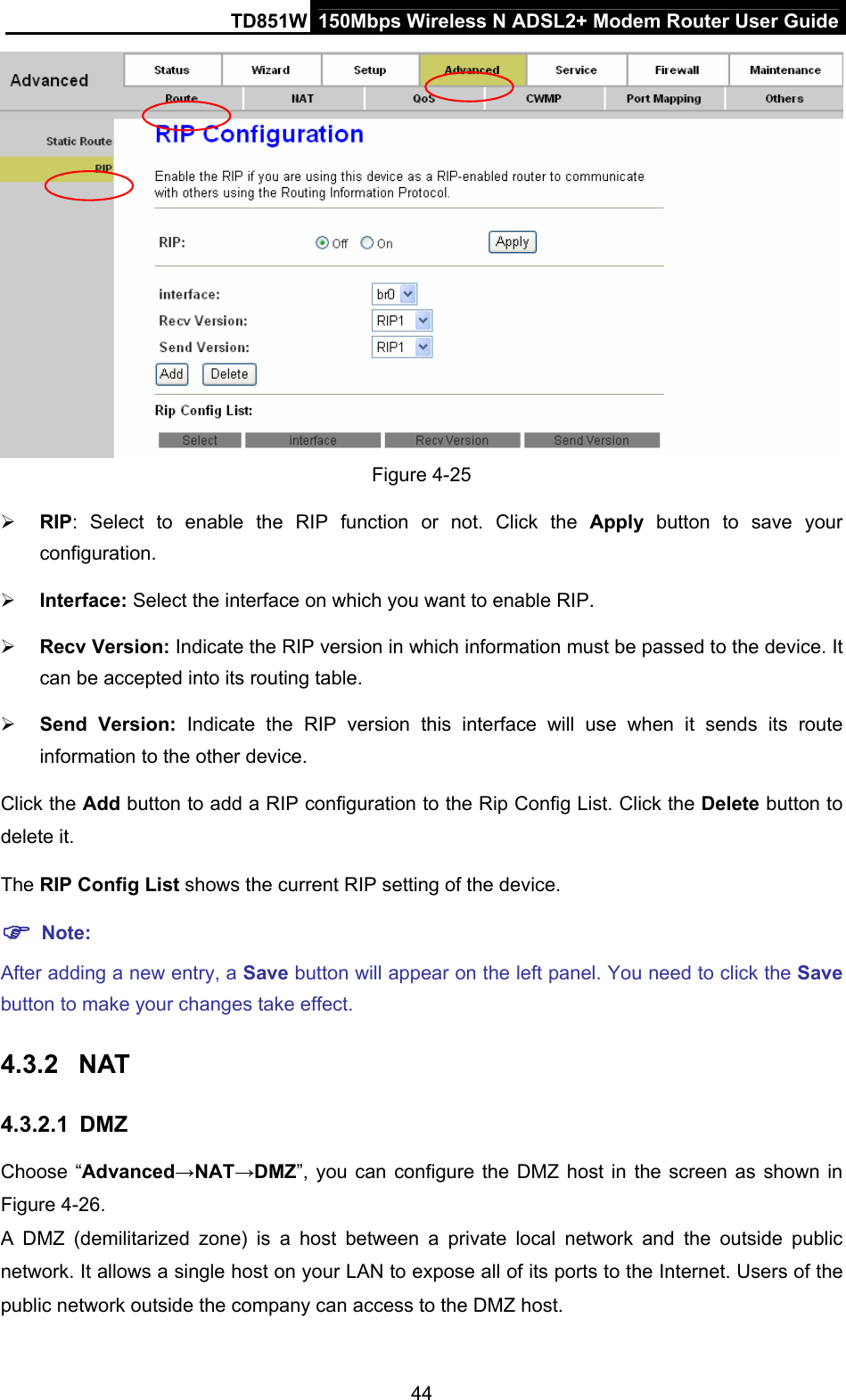
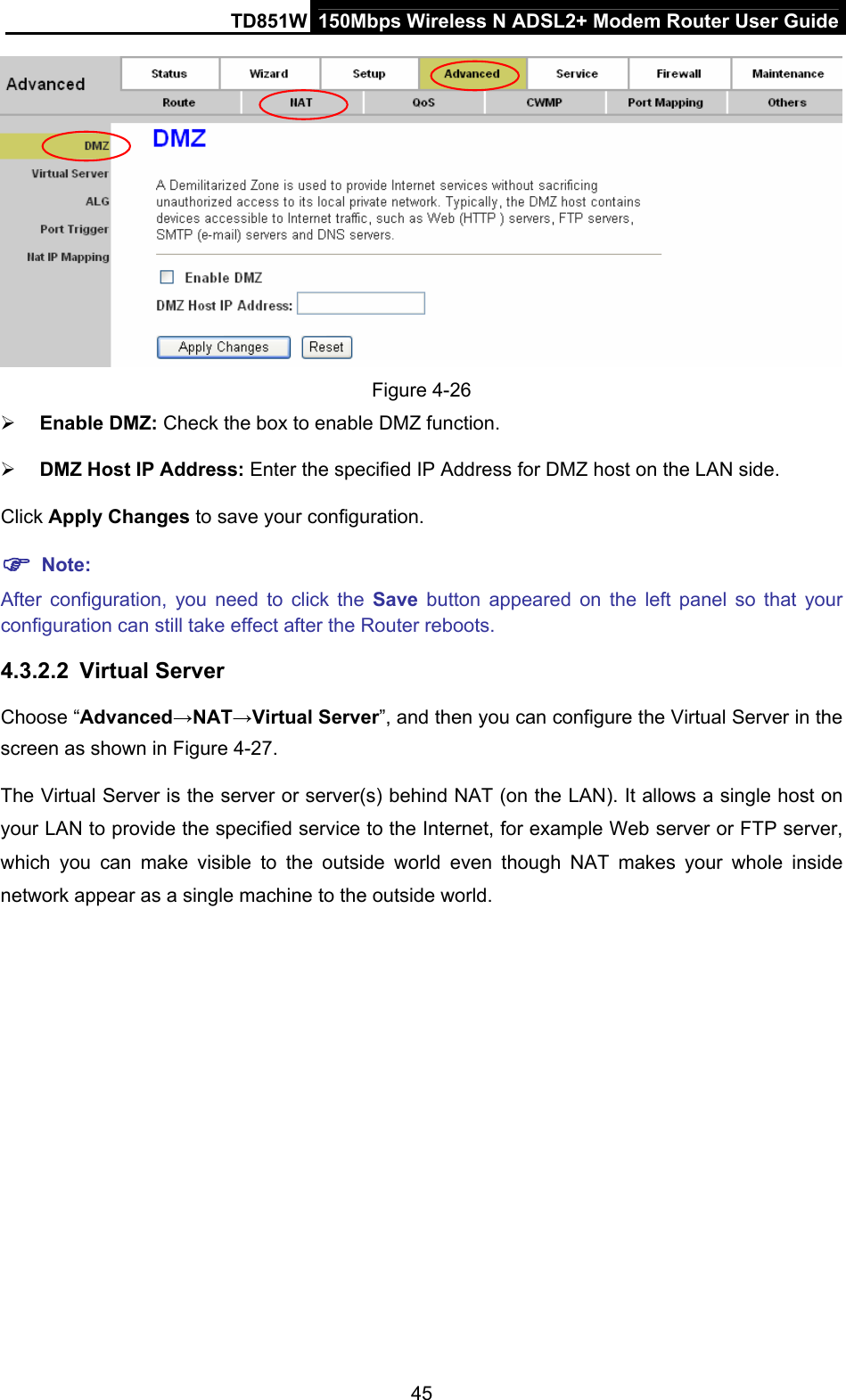
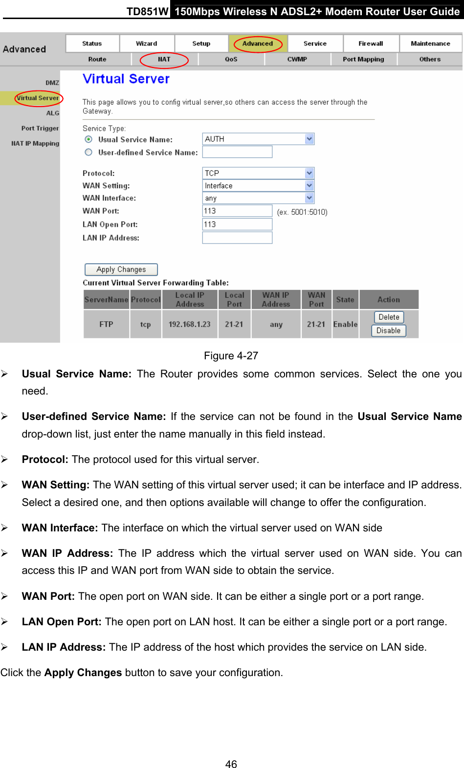
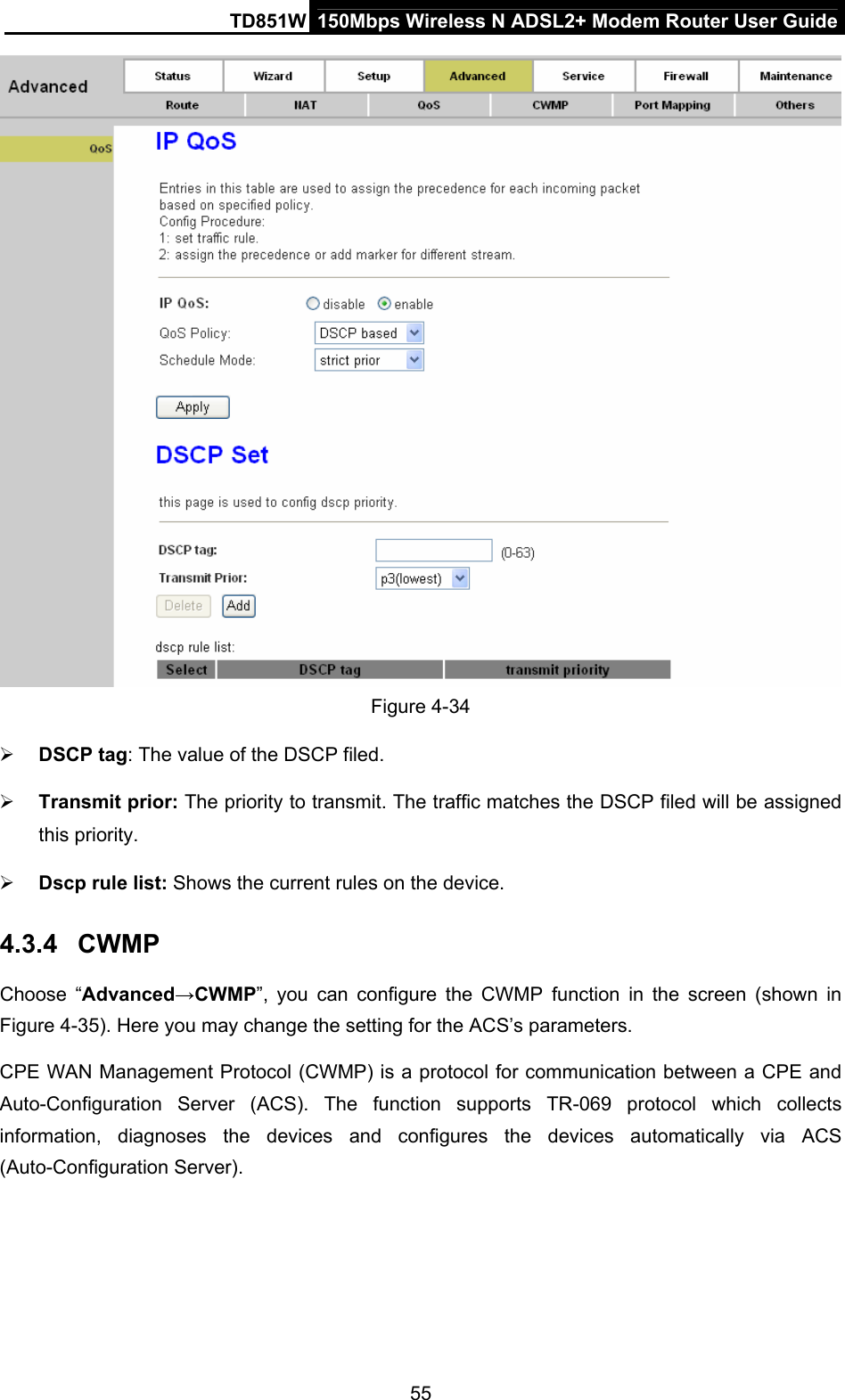
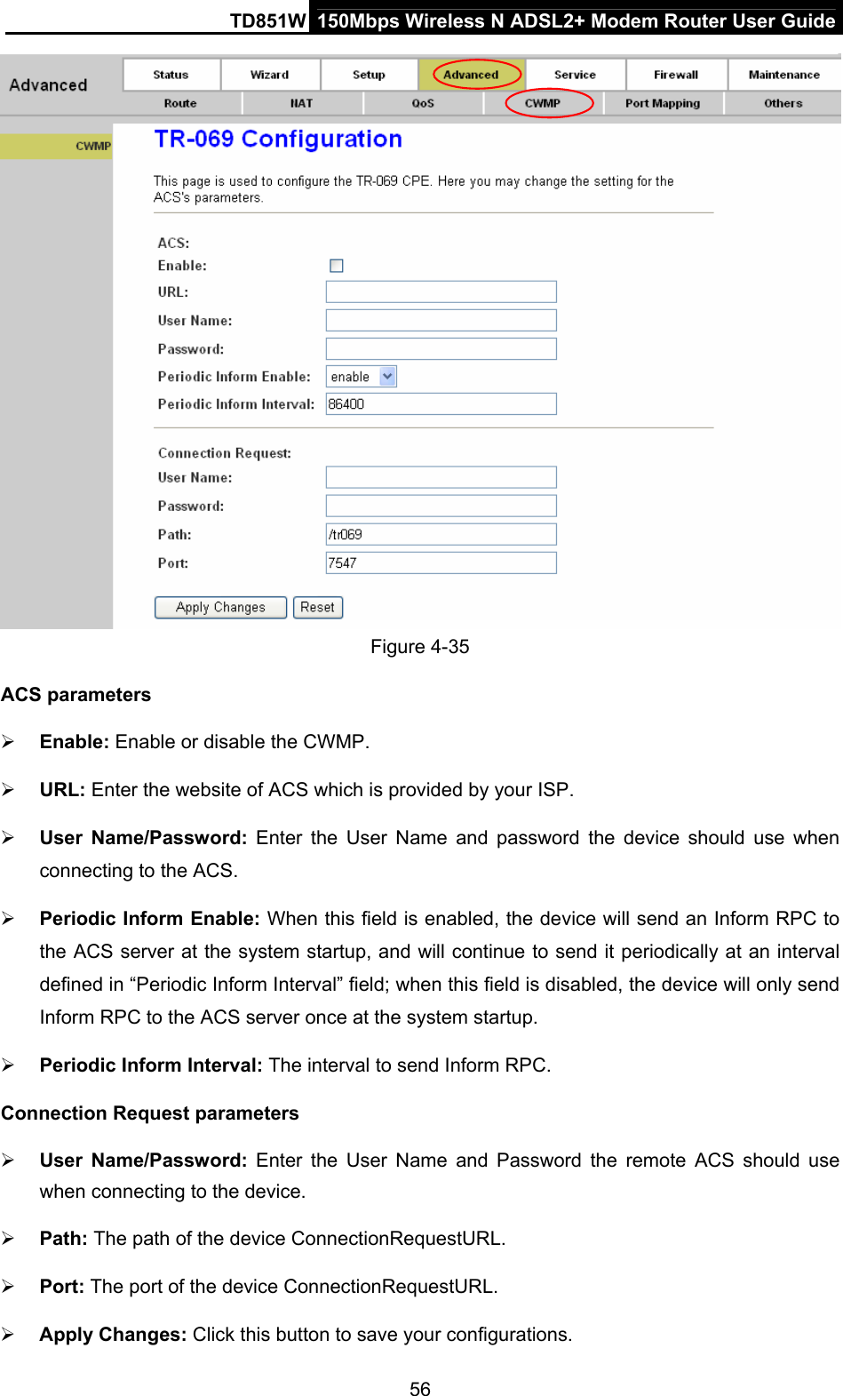
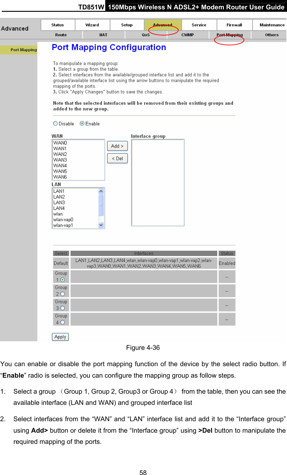
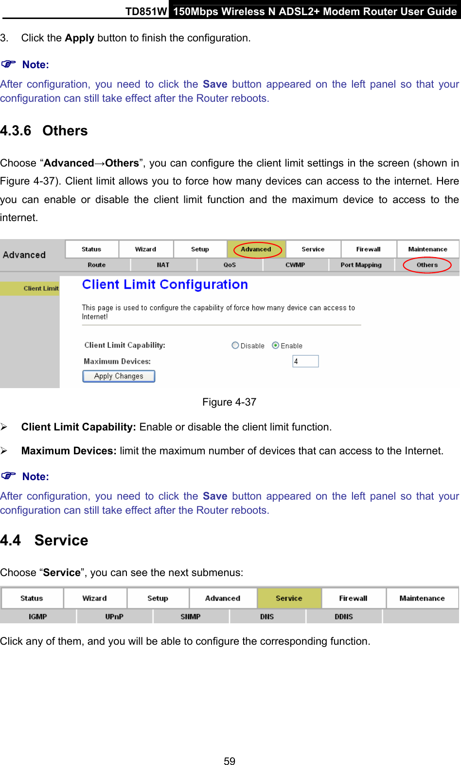
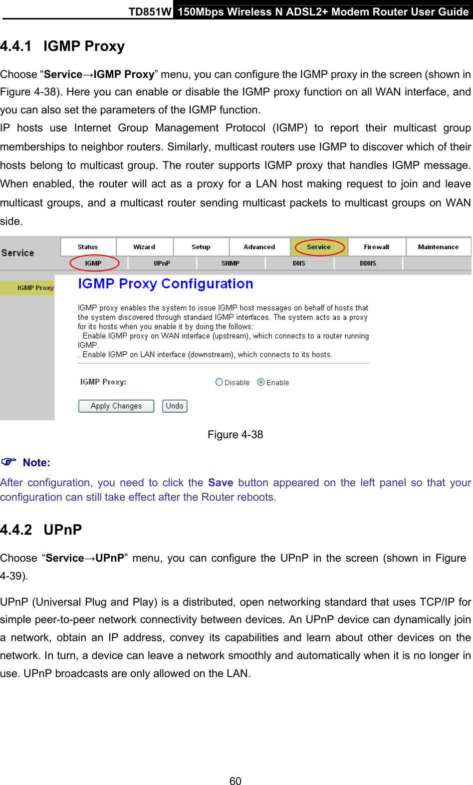
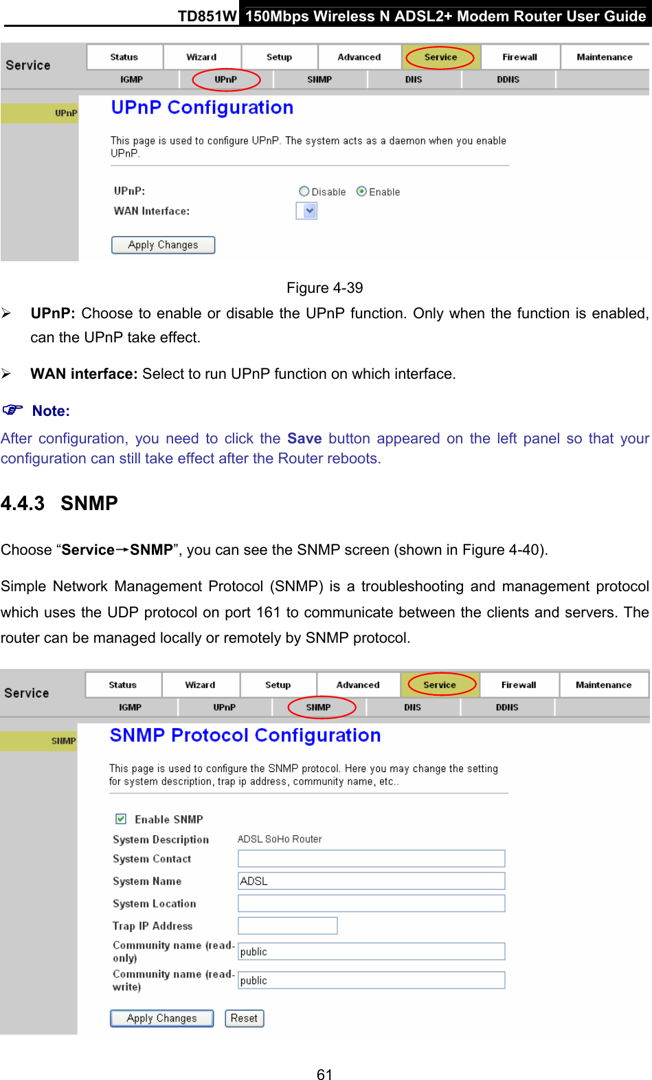
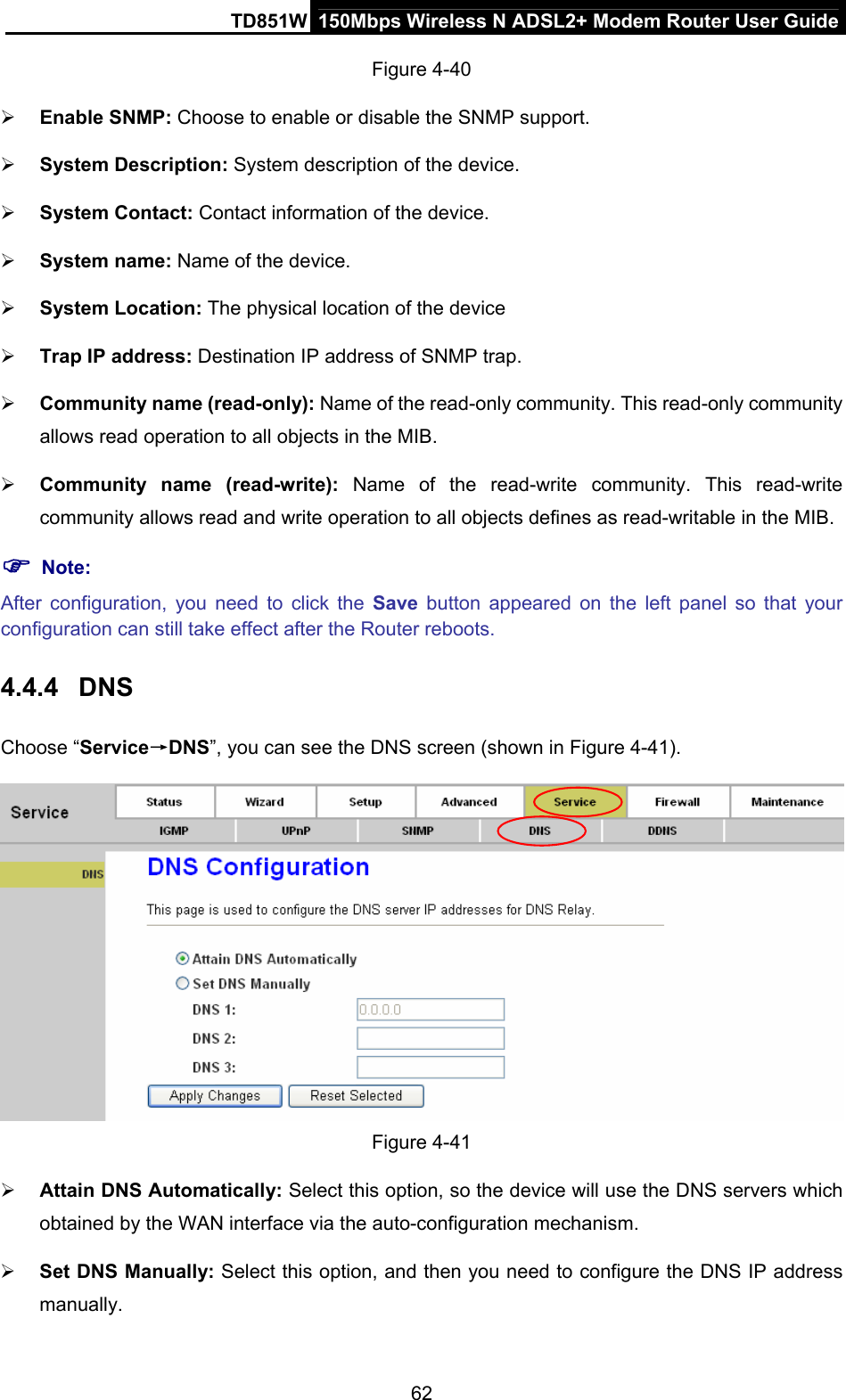
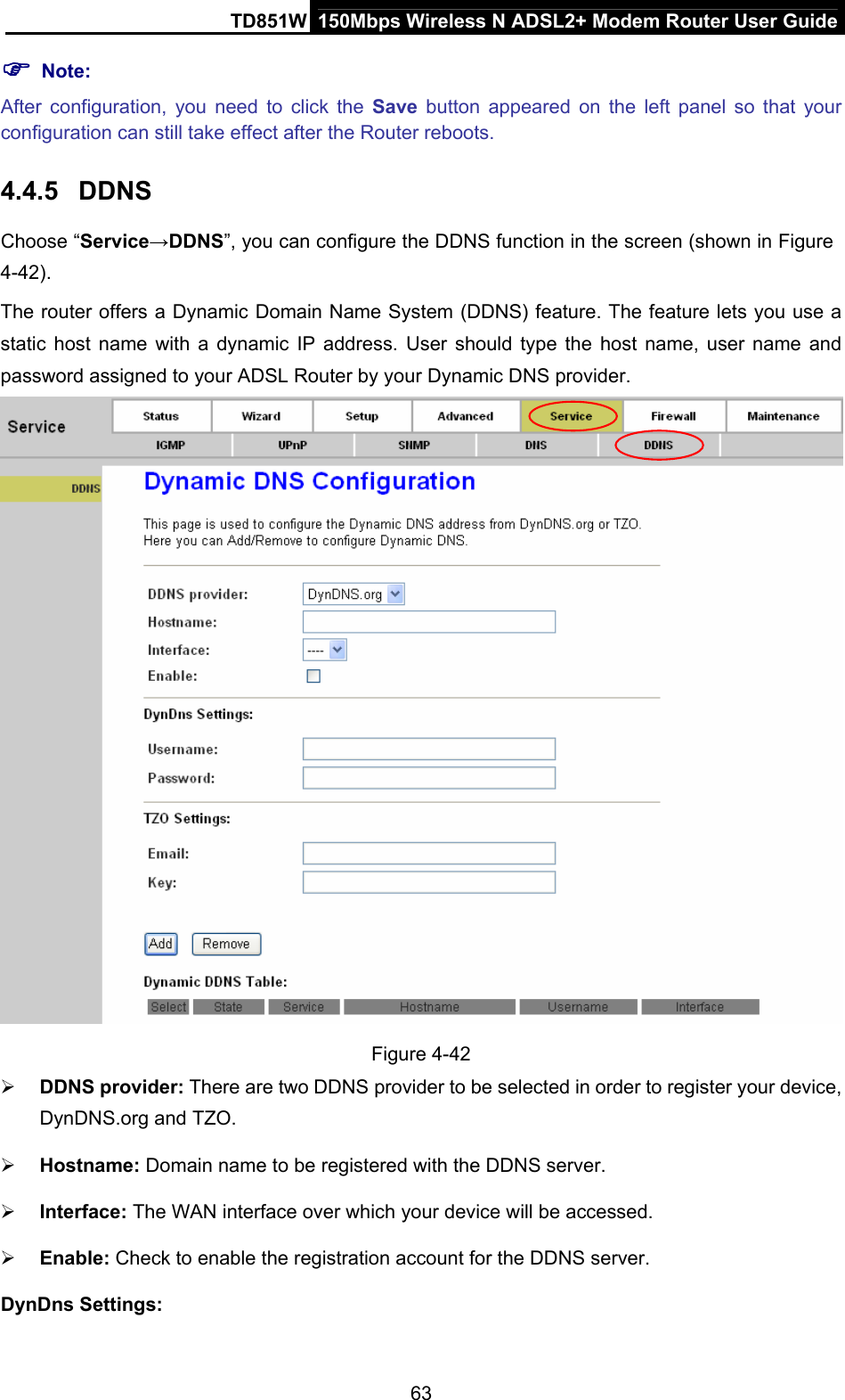
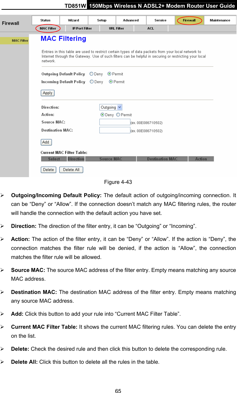
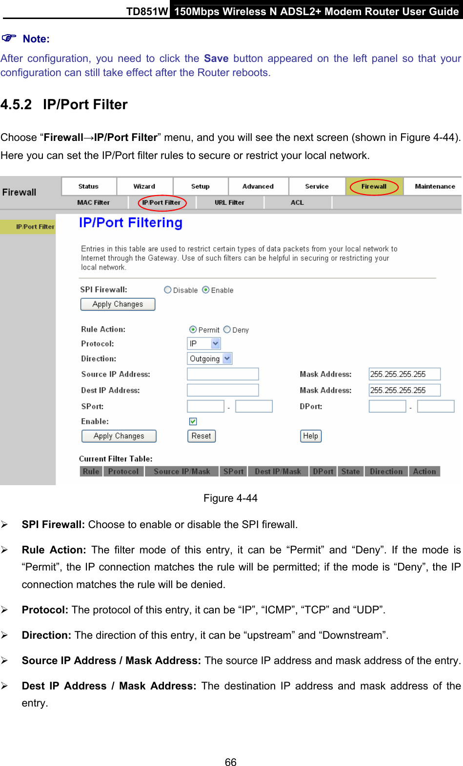
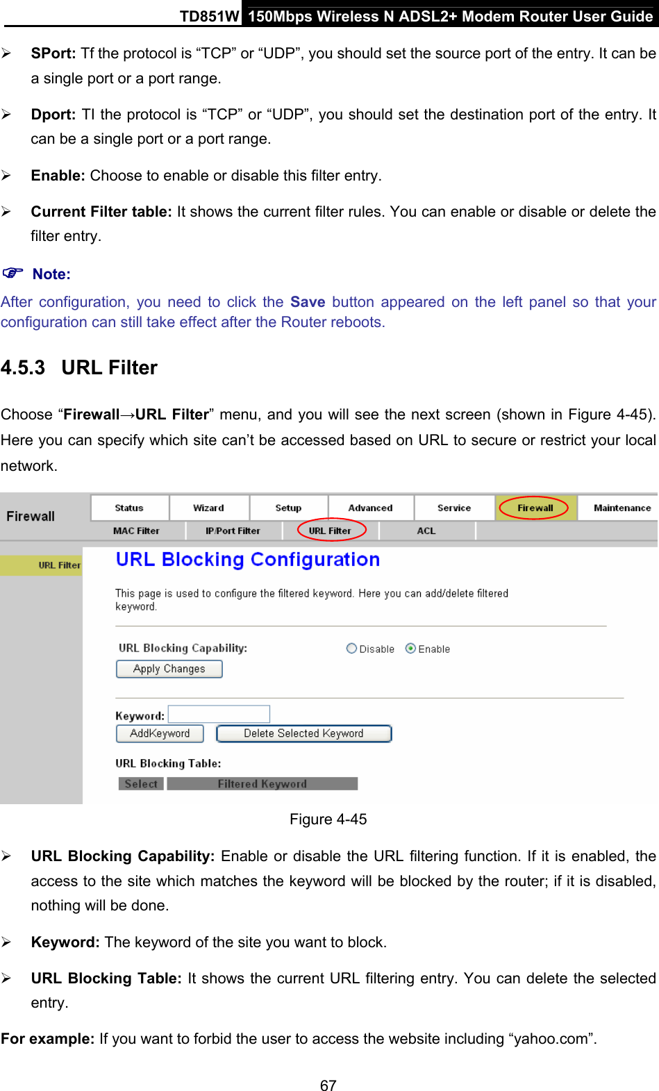
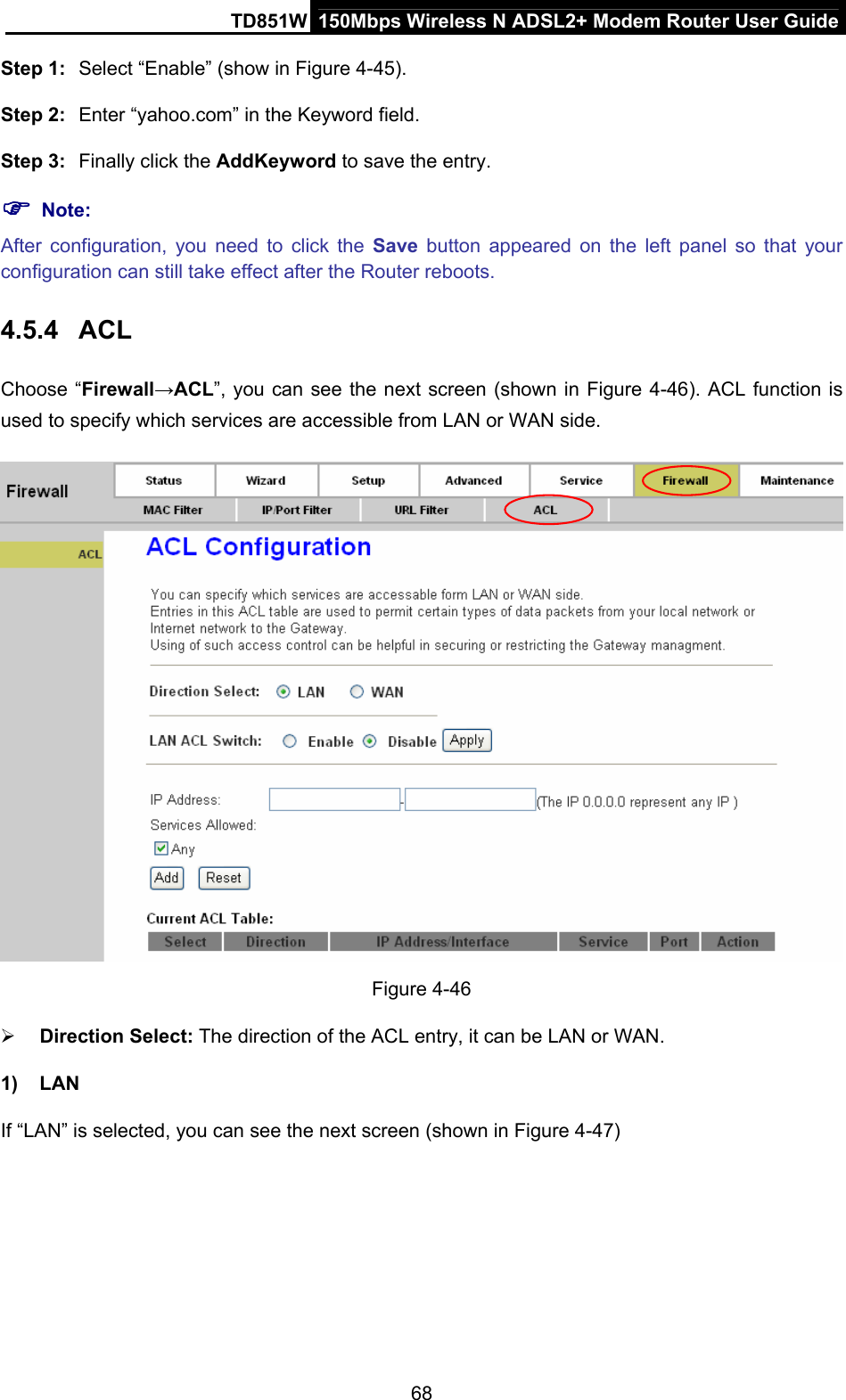
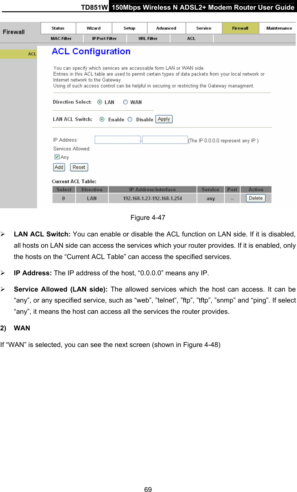
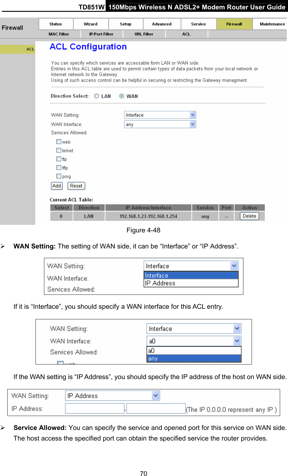
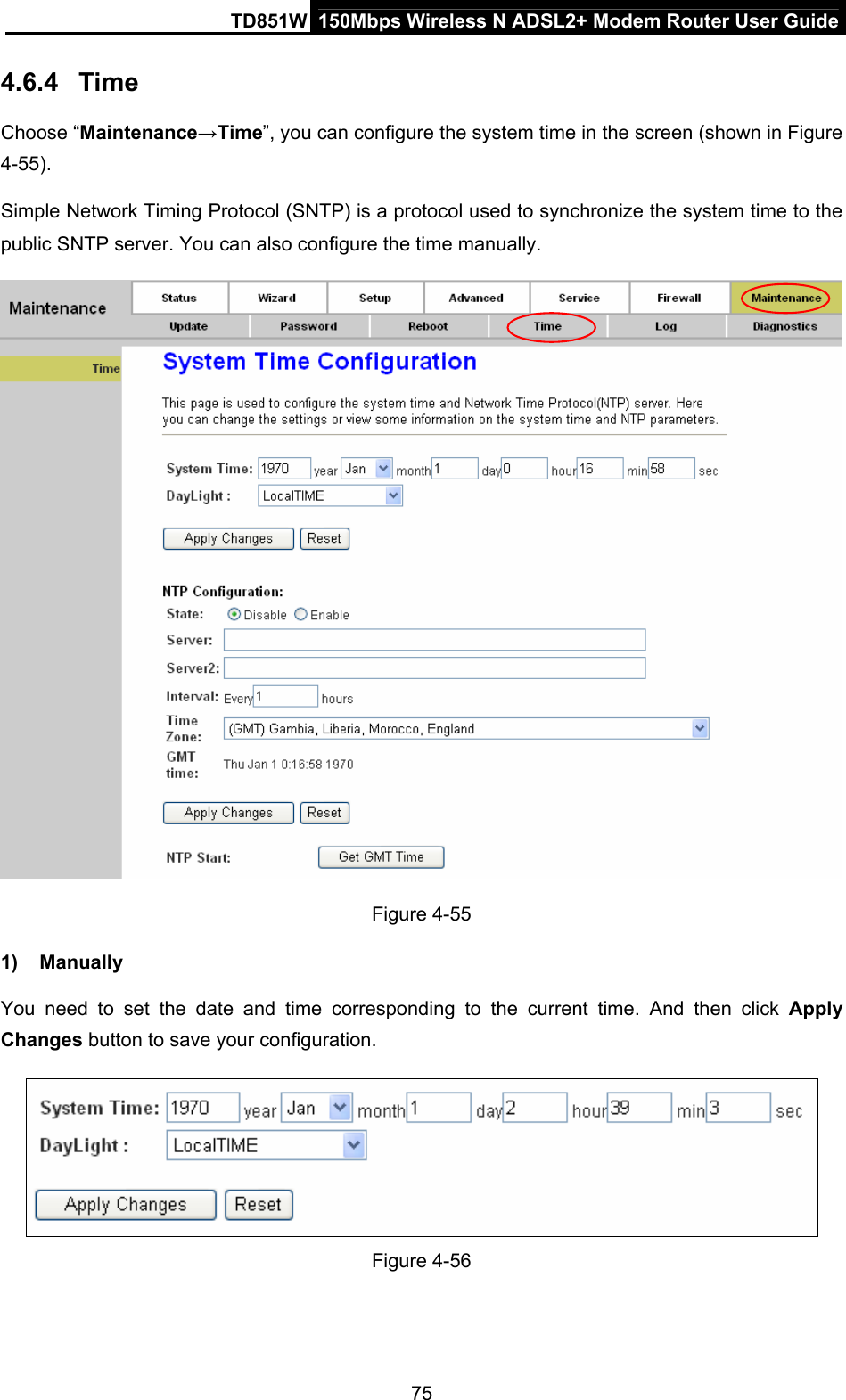
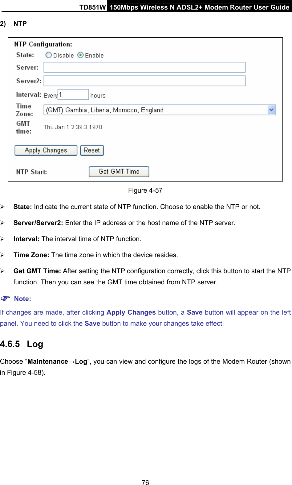
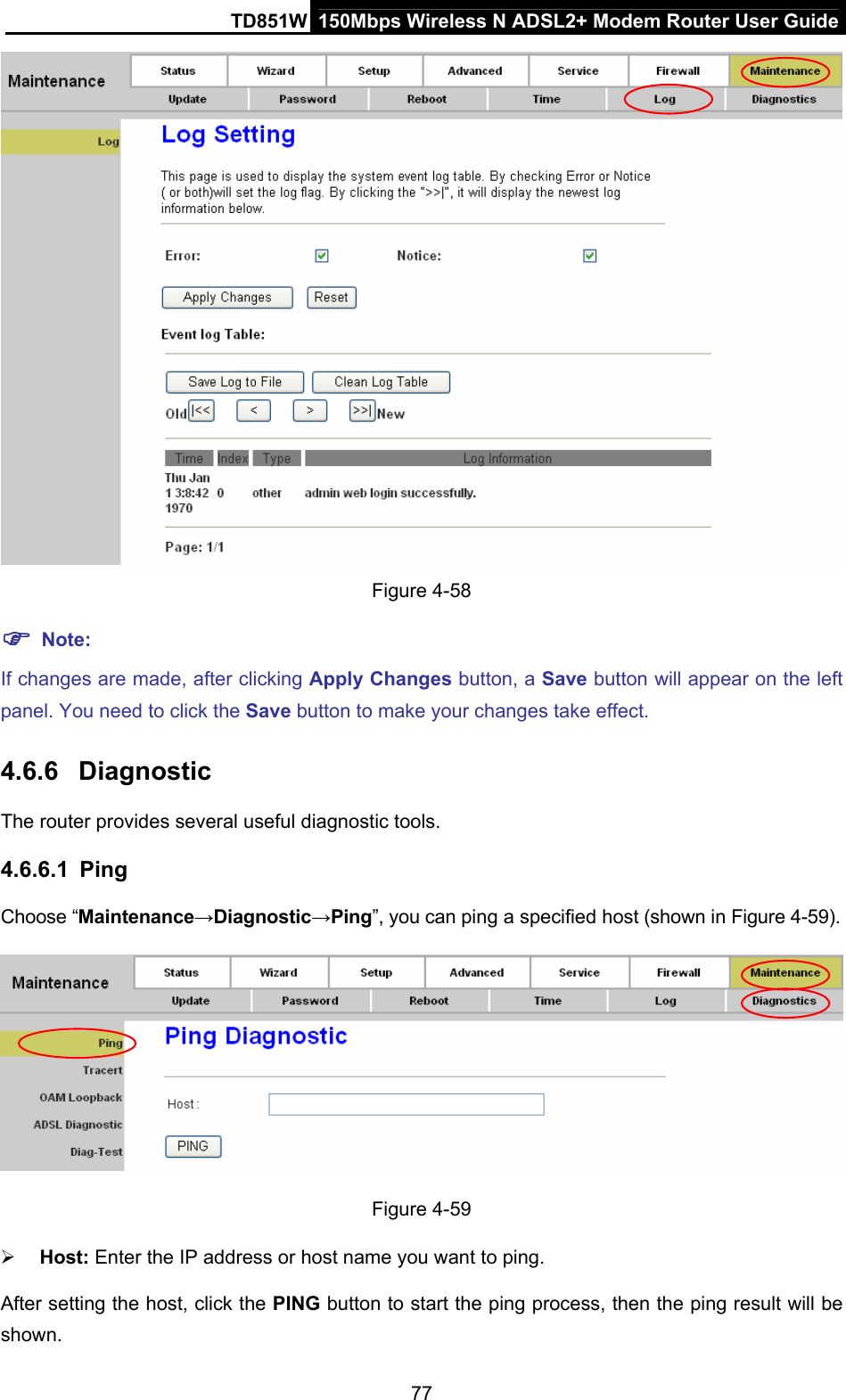
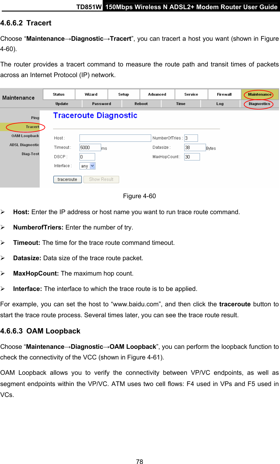
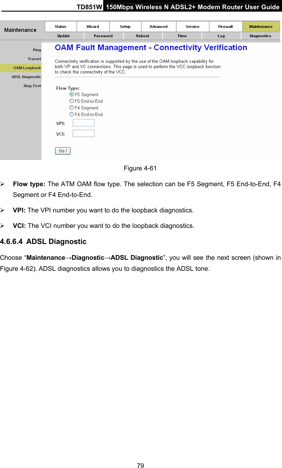
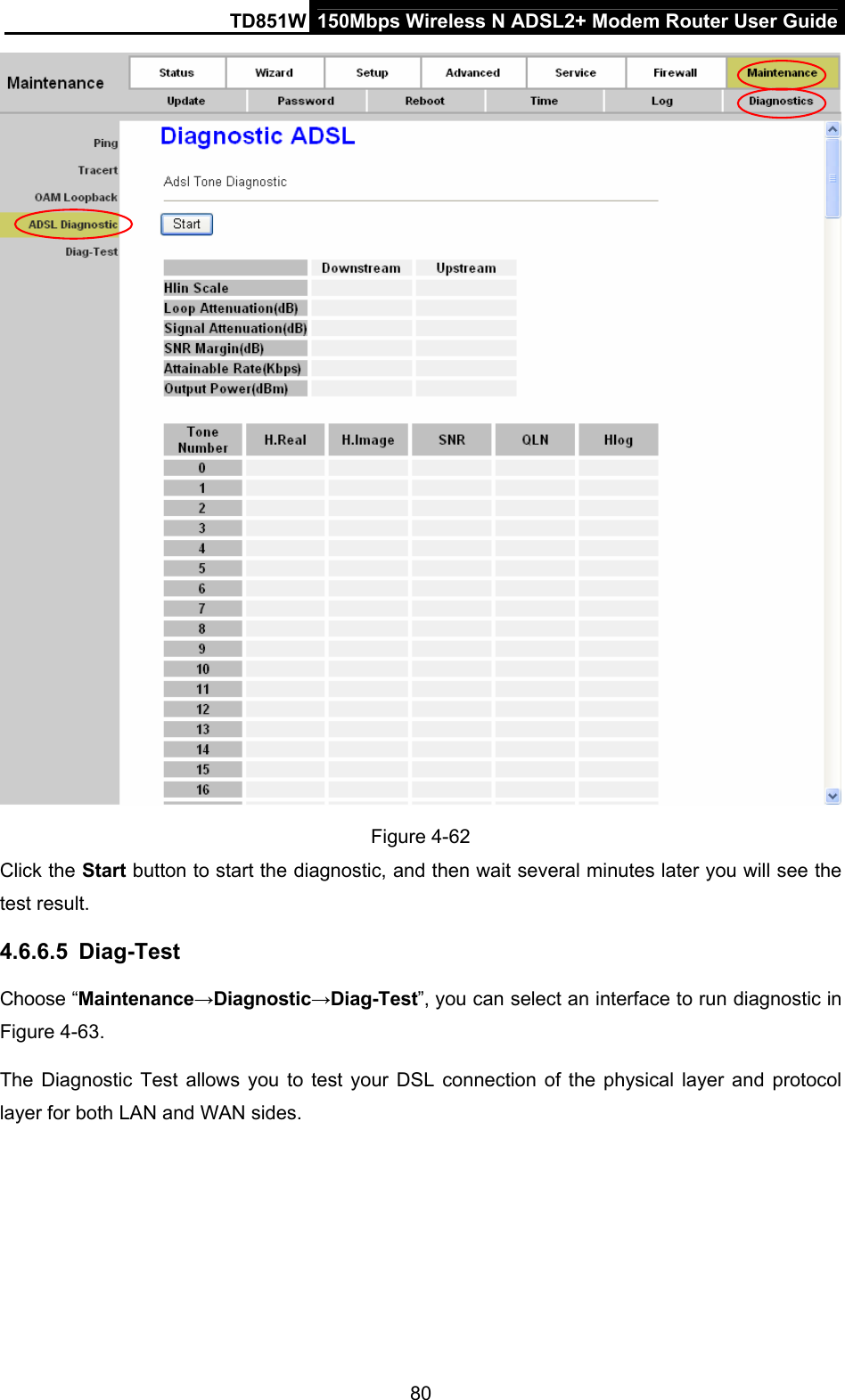
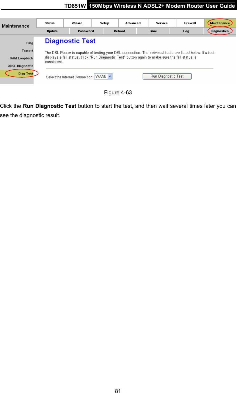
TD851W User Guide
Navigation menu
Upload a User Manual
Namespaces
Wiki Guide
HTML
PDF
Info
Views
User Manual
Discussion / Help
Navigation