TP Link Technologies TD854W 150Mbps Wireless N ADSL2+Modem Router User Manual TD854W User Guide
TP-Link Technologies Co., Ltd. 150Mbps Wireless N ADSL2+Modem Router TD854W User Guide
UserManual.wiki
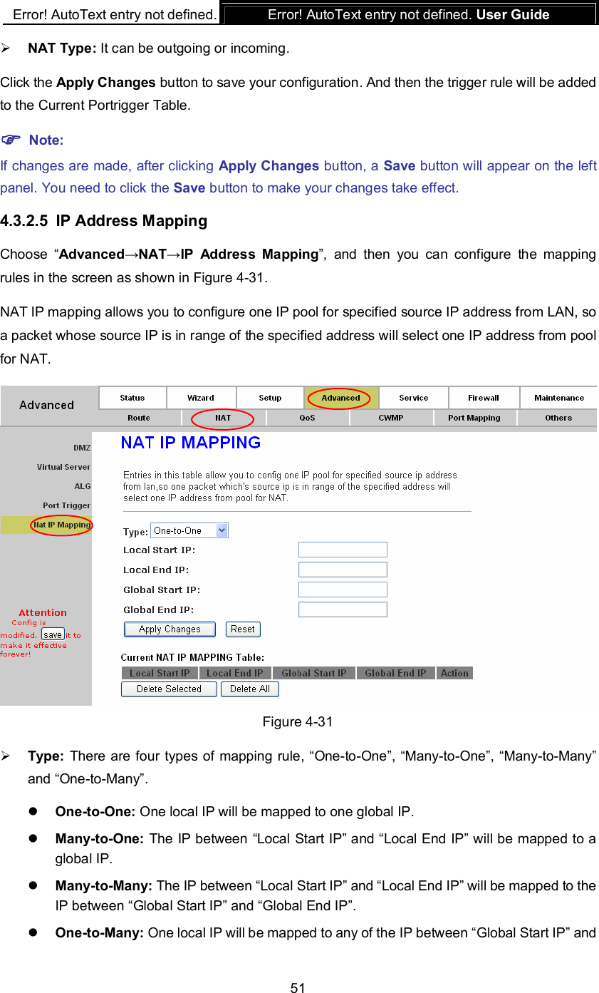
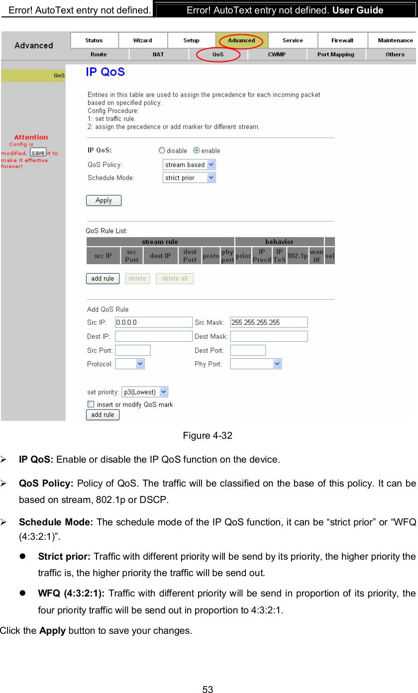
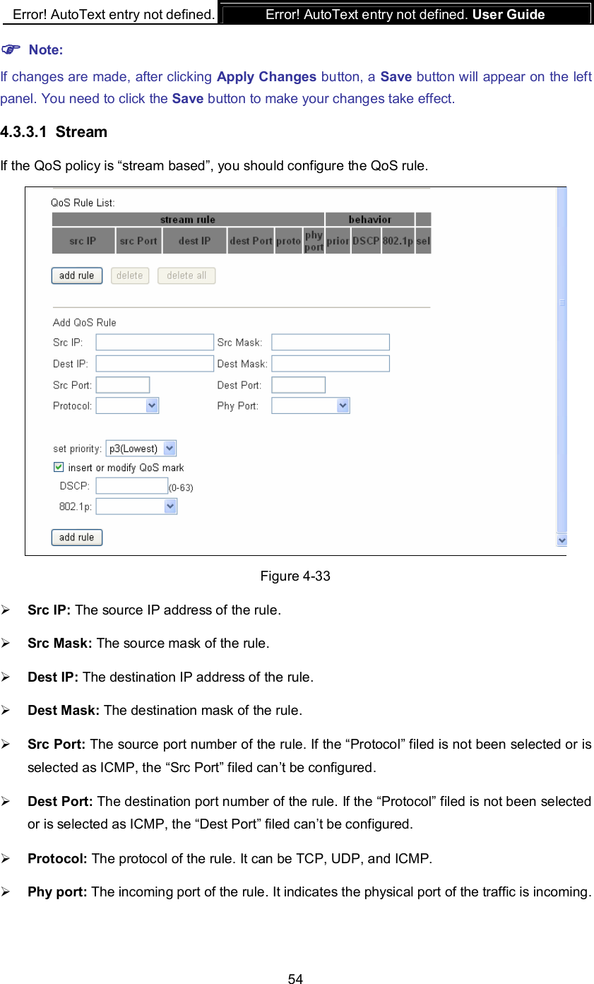
>
TP Link Technologies
>
TD854W User Manual
TD854W_User Guide
Navigation menu
Upload a User Manual
Namespaces
Wiki Guide
HTML
PDF
Info
Views
User Manual
Discussion / Help
Navigation
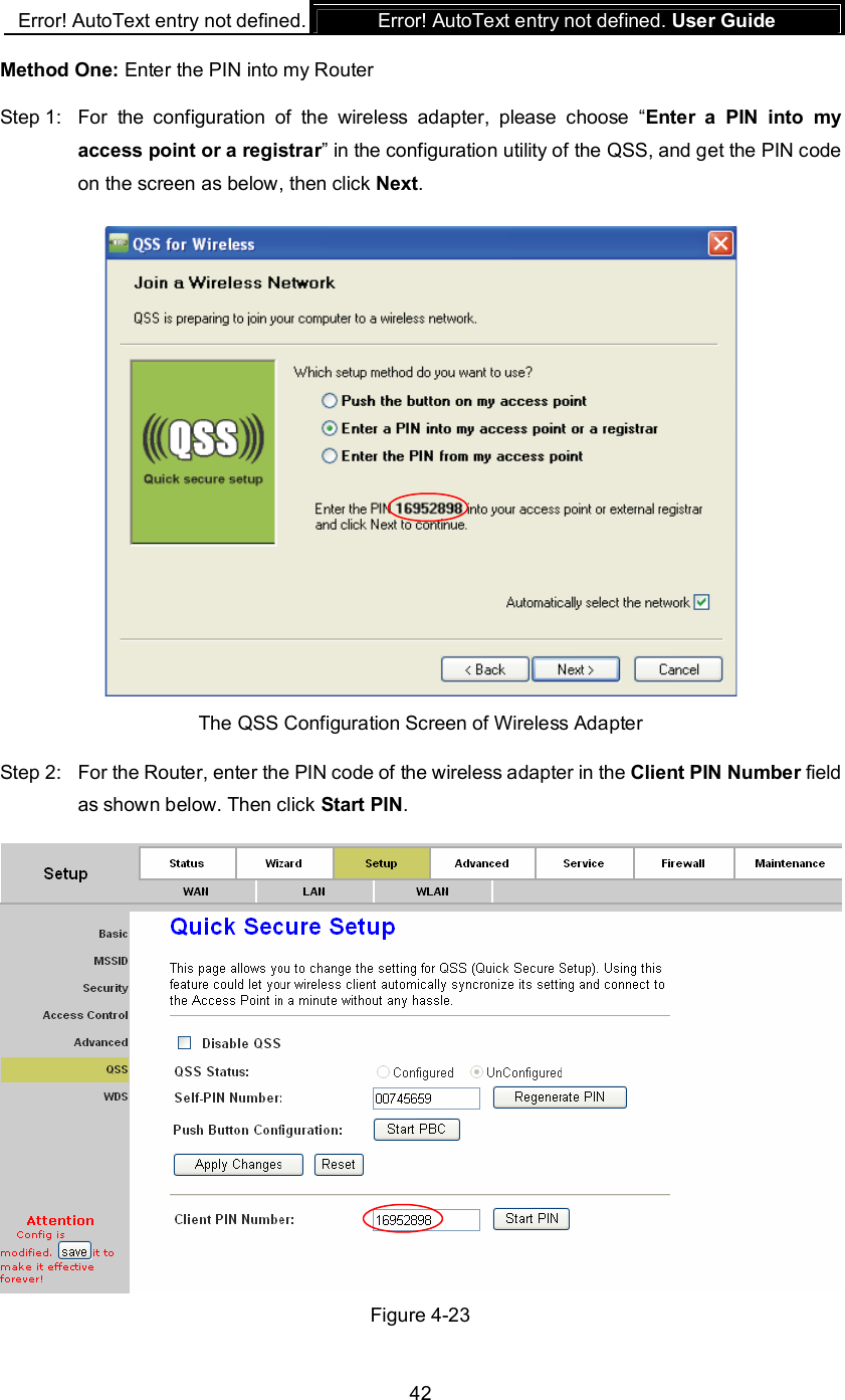
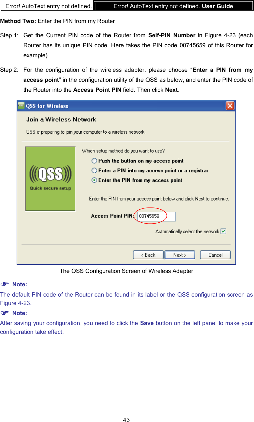
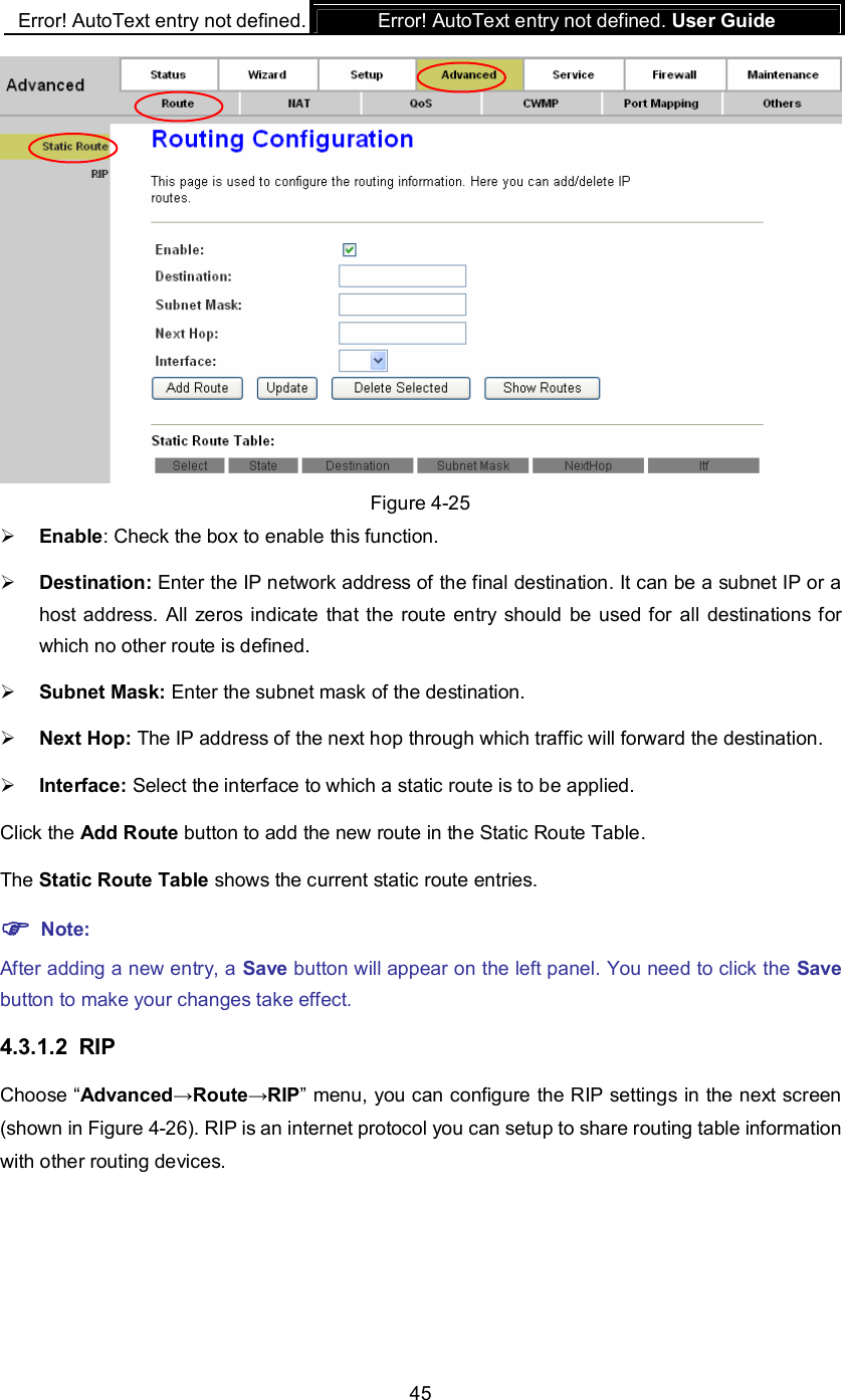
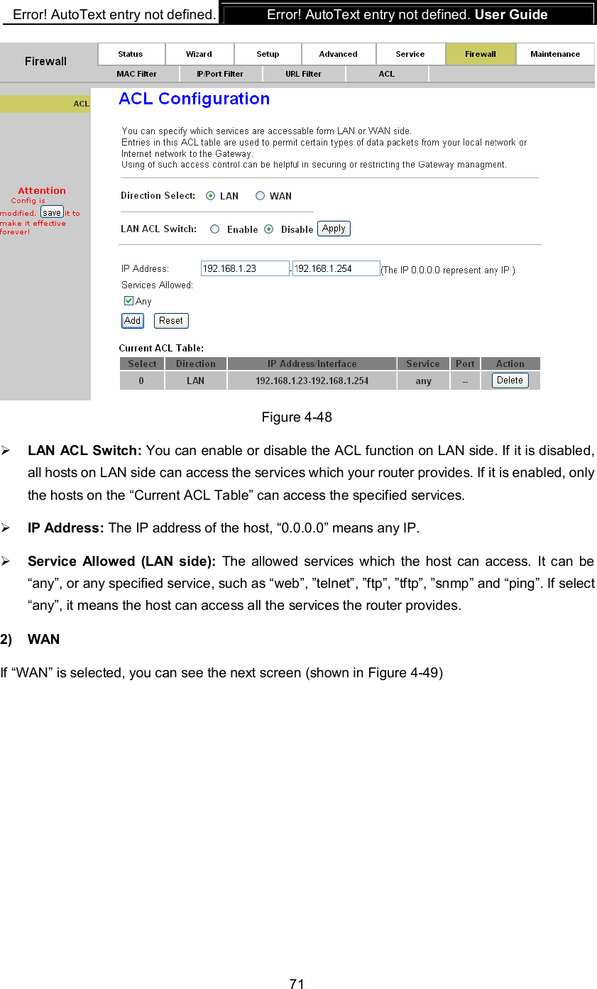
![Error! AutoText entry not defined. Error! AutoText entry not defined. User Guide 44 4.2.3.7 WDS Figure 4-24 Enable WDS: Select to enable WDS. With this function enabled, the Router can bridge two or more WLANs. Add WDS AP: MAC Address: Enter the MAC Address you wish to bridge in the field. Comment: Give a comment. Note: If changes are made, after clicking Apply Changes button, a Save button will appear on the left panel. You need to click the Save button to make your changes take effect. 4.3 Advanced Choose “Advanced”, you can see the next submenus: Click any of them, and you will be able to configure the corresponding function. 4.3.1 Route 4.3.1.1 Static Route Choose “Advanced→Route→Static Route” menu, you can configure the routing information in the next screen (shown in Figure 4-25). Here you can add or delete IP routes. Comment [znh1]: 无法设置](https://usermanual.wiki/TP-Link-Technologies/TD854W/User-Guide-1502761-Page-50.png)
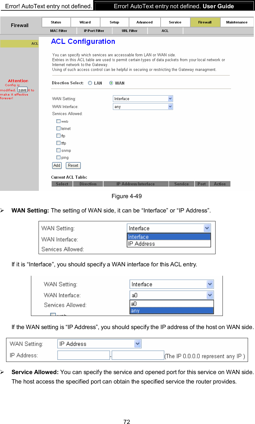
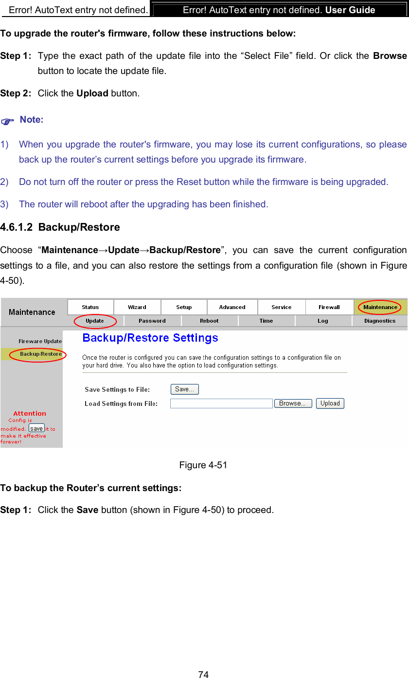
![Error! AutoText entry not defined. Error! AutoText entry not defined. User Guide 73 Current ACL Table: It shows the current ACL setting. 4.6 Maintenance Choose “Maintenance”, you can see the next submenus: Click any of them, and you will be able to configure the corresponding function. 4.6.1 Update 4.6.1.1 Firmware Update Choose “Maintenance→Update→Firmware Update”, you can upgrade the firmware of the Router in the screen (shown in Figure 4-50). Make sure the firmware you want to use is on the local hard drive of the computer. Click Browse to find the local hard drive and locate the firmware to be used for upgrade. Figure 4-50 Comment [znh2]: Fireware](https://usermanual.wiki/TP-Link-Technologies/TD854W/User-Guide-1502761-Page-79.png)