TP Link Technologies TDW8950NV2 150Mbps Wireless N ADSL2 + Modem Router User Manual TE7TDW8950NV2 UM

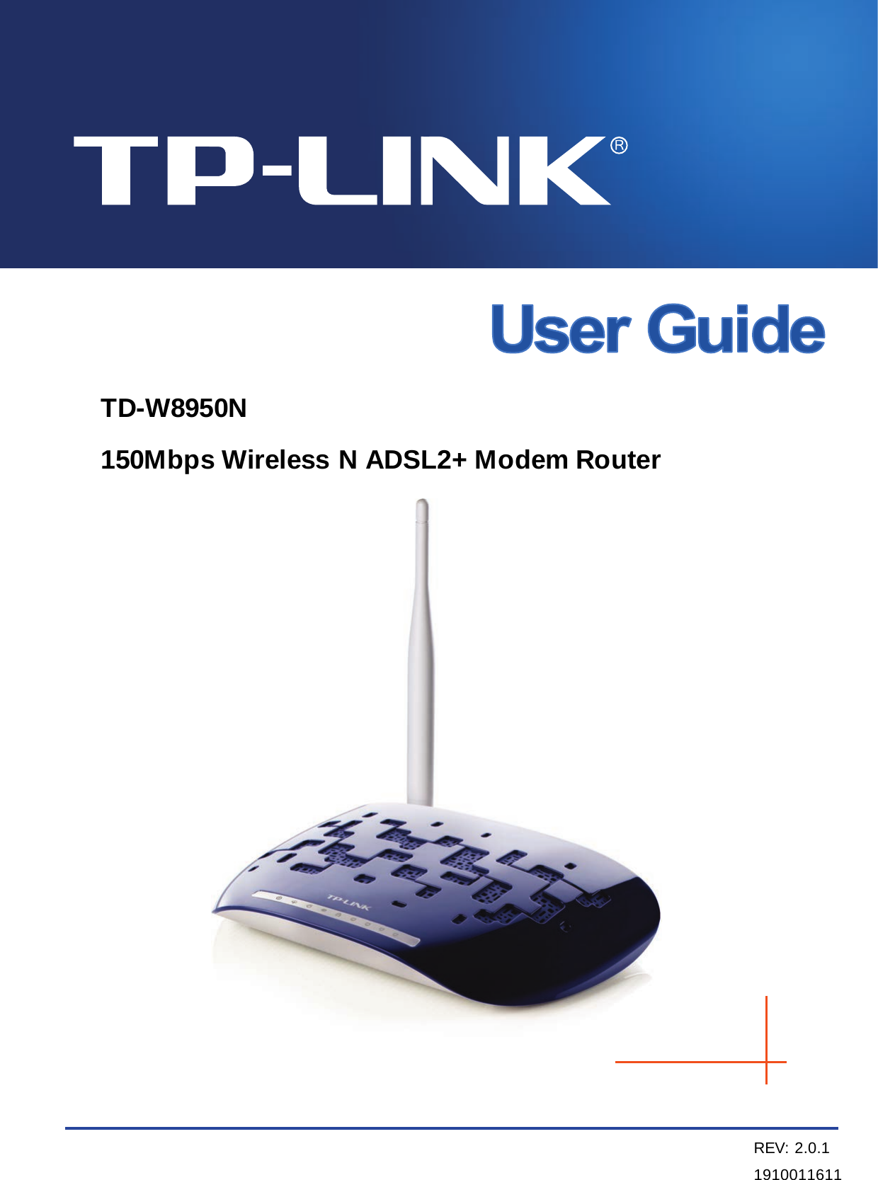
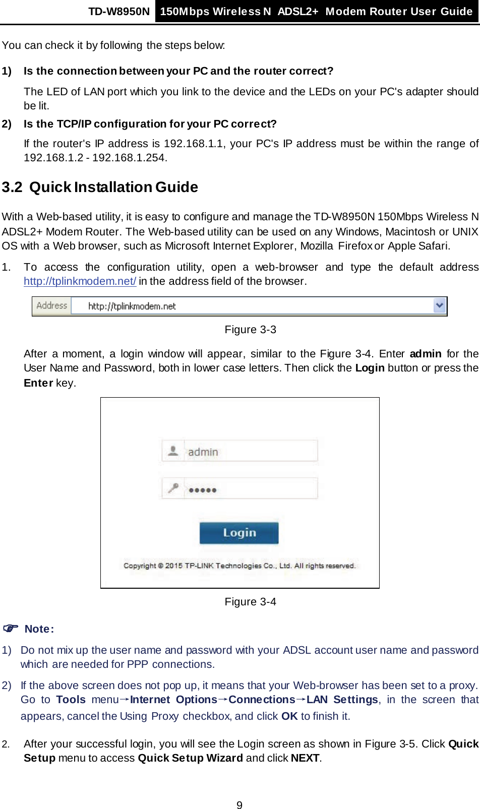
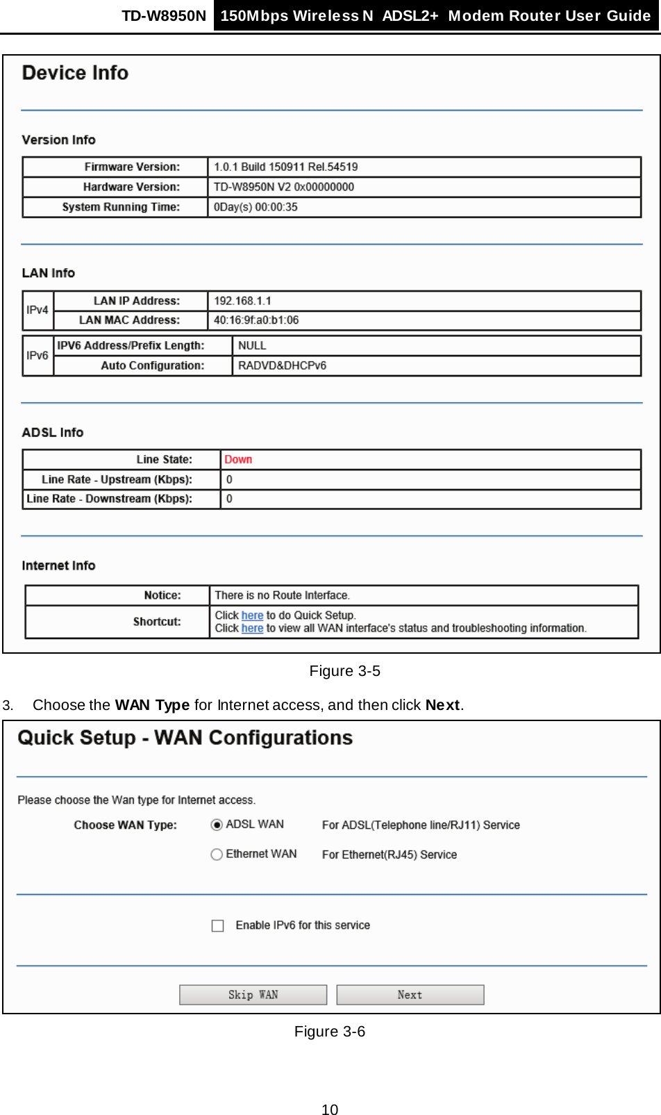
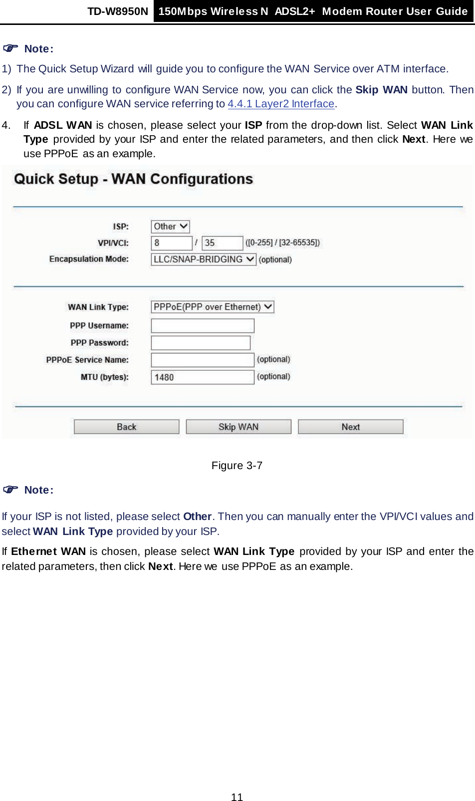
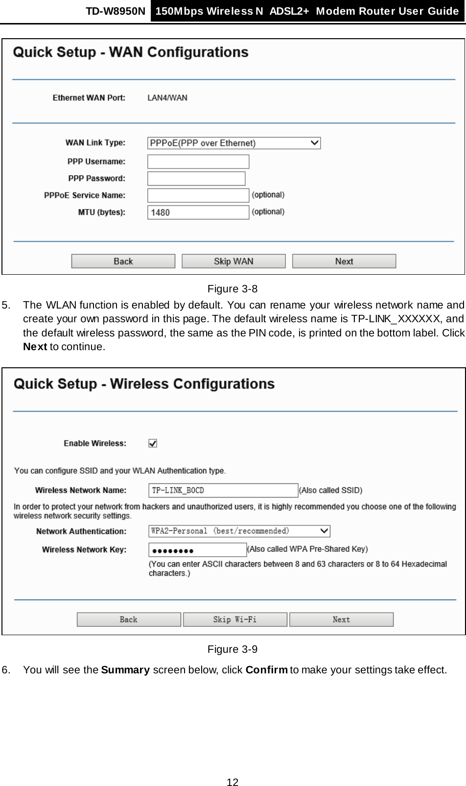
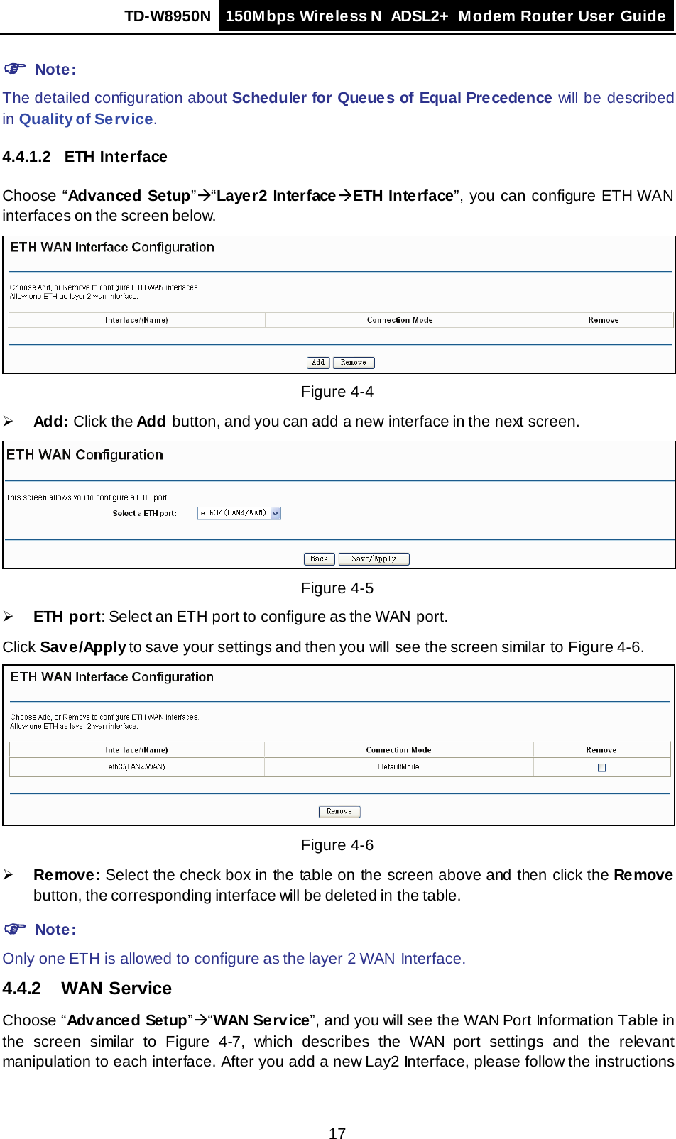
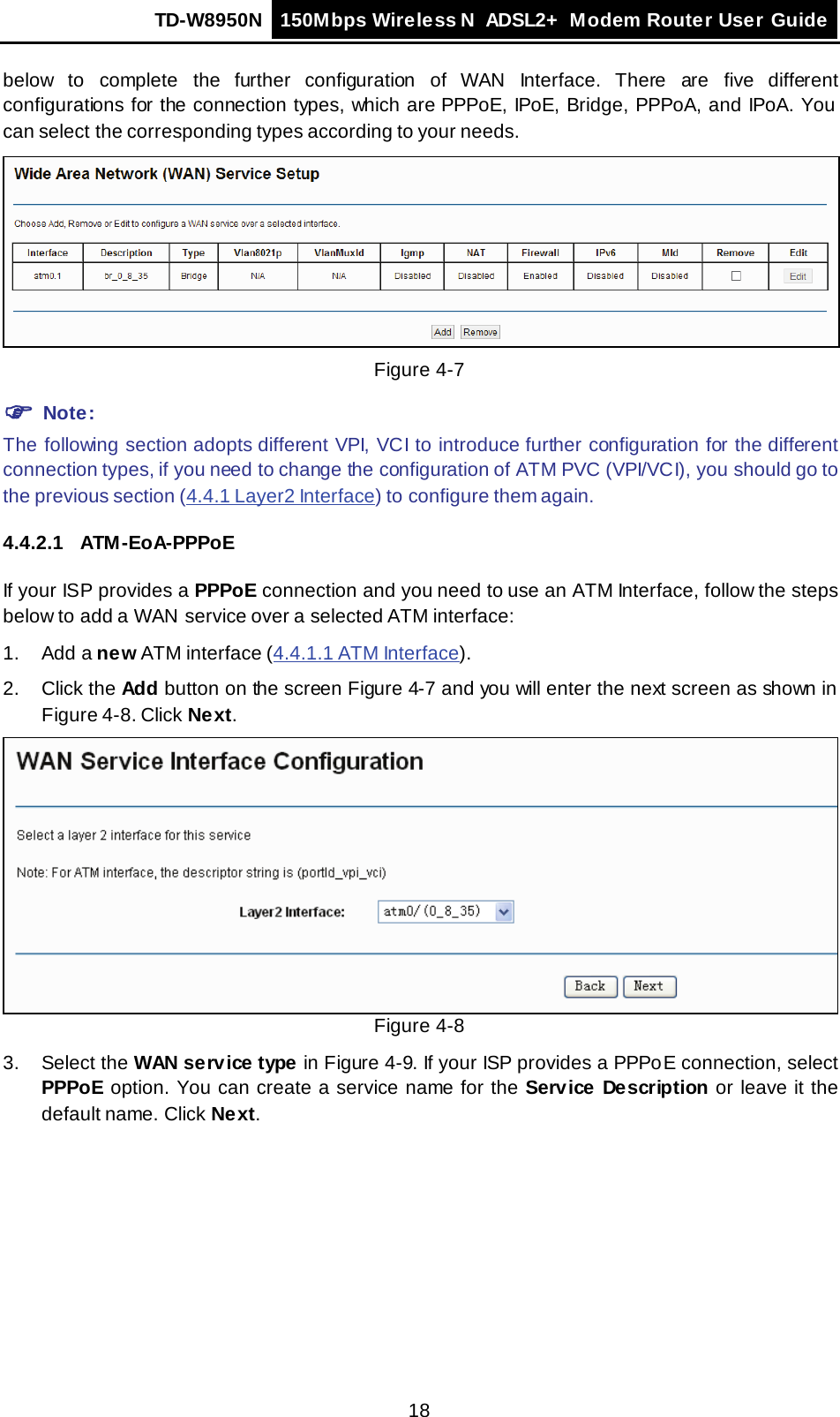
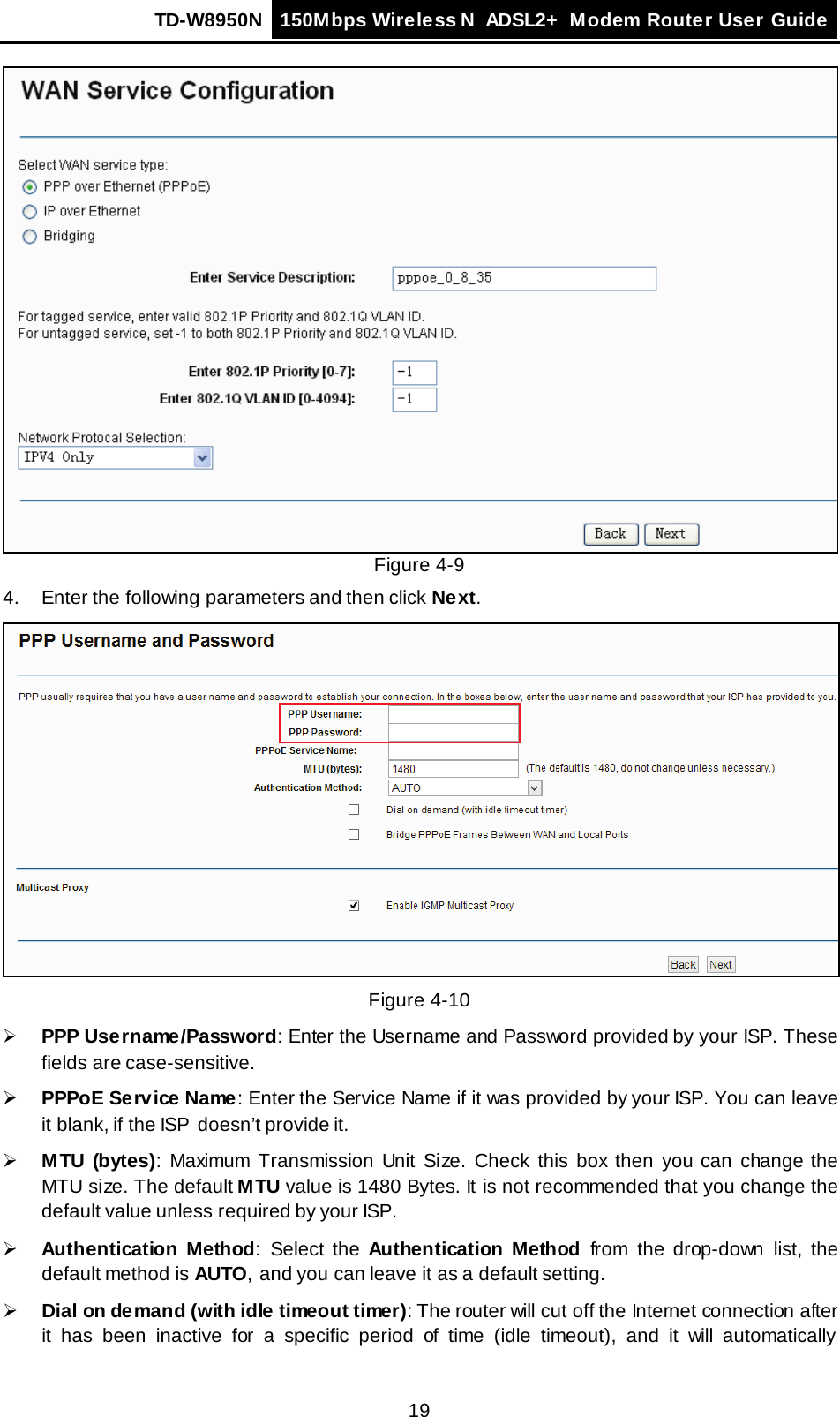
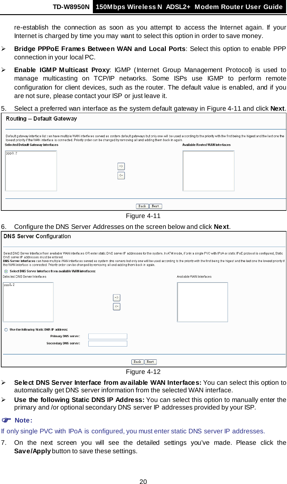
TP-Link Technologies Co., Ltd. 150Mbps Wireless N ADSL2 + Modem Router TE7TDW8950NV2 UM

TE7TDW8950NV2-UM

   TD-W8950N 150Mbps Wireless N ADSL2+ Modem Router  REV: 2.0.1 1910011611
  COPYRIGHT  & TRADEMARKS Specifications are subject to change without notice.   is a registered trademark of TP-LINK TECHNOLOGIES CO., LTD.  Other brands and product names are trademarks or registered trademarks of their respective holders. No part of the specifications may be reproduced in any form or by any means or used to make any derivative such as translation, transformation, or adaptation without permission from TP-LINK TECHNOLOGIES CO., LTD.  Copyright © 2016 TP-LINK TECHNOLOGIES CO., LTD.  All rights reserved. http://www.tp-link.com
  FCC STATEMENT  This equipment has been tested and found to comply with the limits for a Class B digital device, pursuant to part 15 of the FCC Rules. These limits are designed to provide reasonable protection against harmful interference in a residential installation. This equipment generates, uses and can radiate radio frequency energy and, if not installed and used in accordance with the instructions, may cause harmful interference to radio communications. However, there is no guarantee that interference will not occur in a particular installation. If this equipment does cause harmful interference to radio or television reception, which can be determined by turning the equipment off and on, the user is encouraged to try to correct the interference by one or more of the following measures: • Reorient or relocate the receiving antenna. • Increase the separation between the equipment and receiver. • Connect the equipment into an outlet on a circuit different from that to which the receiver is connected.   • Consult the dealer or an experienced radio/ TV technician for help. This device complies with part 15 of the FCC Rules. Operation is subject to the following two conditions: 1) This device may not cause harmful interference. 2) This device must accept any interference received, including interference that may cause undesired operation. Any changes or modifications not expressly approved by the party responsible for compliance could void the user’s authority to operate the equipment. Note:  The manufacturer is not responsible for any radio or TV interference caused by unauthorized modifications to this equipment. Such modifications could void the user’s authority to operate the equipment. FCC RF Radiation Exposure Statement: This equipment complies with FCC RF radiation exposure limits set forth for an uncontrolled environment. This device and its antenna must not be co-located or operating in conjunction with any other antenna or transmitter. “To comply with FCC RF exposure compliance requirements, this grant is applicable to only Mobile Configurations. The antennas used for this transmitter must be installed to provide a separation distance of at least 20 cm from all persons and must not be co-located or operating in conjunction with  any other antenna or transmitter.” CE Mark Warning  This is a class B product. In a domestic environment, this product may cause radio interference, in which  case the user may be required to take adequate measures.
  RF Exposure Information This device meets the EU requirements (1999/5/EC Article 3.1a) on the limitation of exposure of the general public to electromagnetic fields by way of health protection. Canadian Compliance Statement This device complies with Industry Canada license-exempt  RSSs.  Operation is subject to the following two conditions: (1) This device may not cause interference, and (2) This device must accept any interference, including interference that may cause undesired operation of the device. Le présent appareil est conforme aux CNR d’Industrie Canada applicables aux appareils radio exempts de licence. L’exploitation est autorisée aux deux conditions suivantes : (1) l’appareil ne doit pas produire de brouillage; (2) l’utilisateur de l’appareil doit accepter tout brouillage radioélectrique subi, meme si le brouillage est susceptible d’en compromettre le fonctionnement. Radiation Exposure Statement:   This equipment complies with IC radiation exposure limits set forth for an uncontrolled environment. This equipment should be installed and operated with minimum distance 20cm between the radiator & your body.   Déclaration d'exposition aux radiations:   Cet équipement est conforme aux limites d'exposition aux rayonnements IC établies pour un environnement non contrôlé. Cet équipement doit être installé et utilisé avec un minimum de 20 cm de distance entre la source de rayonnement et votre corps. Industry Canada Statement CAN ICES-3 (B)/NMB-3(B) Korea Warning Statements 당해 무선설비는 운용중 전파혼신 가능성이 있음. NCC Notice 注意!  依據 低功率電波輻射性電機管理辦法 第十二條 經型式認證合格之低功率射頻電機,非經許可,公司、商號或使用者均不得擅自變更頻率、加大功率或變更原設計之特性或功能。 第十四條 低功率射頻電機之使用不得影響飛航安全及干擾合法通行;經發現有干擾現象時,應立即停用,並改善至無干擾時方得繼續使用。前項合法通信,指依電信規定作業之無線電信。低功率射頻電機需忍受合法通信或工業、科學以及醫療用電波輻射性電機設備之干擾。 減少電磁波影響,請妥適使用。
  BSMI Notice 安全諮詢及注意事項 ●請使用原裝電源供應器或只能按照本產品注明的電源類型使用本產品。 ●清潔本產品之前請先拔掉電源線。請勿使用液體、噴霧清潔劑或濕布進行清潔。 ●注意防潮,請勿將水或其他液體潑灑到本產品上。 ●插槽與開口供通風使用,以確保本產品的操作可靠並防止過熱,請勿堵塞或覆蓋開口。 ●請勿將本產品置放於靠近熱源的地方。除非有正常的通風,否則不可放在密閉位置中。 ●請不要私自打開機殼,不要嘗試自行維修本產品,請由授權的專業人士進行此項工作。  Продукт  сертифіковано  згідно  с  правилами  системи  УкрСЕПРО  на  відповідність  вимогам нормативних  документів  та  вимогам,  що  передбачені  чинними  законодавчими  актами України.      Safety Information  When product has power button, the power button is one of the way to shut off the product; when there is no power button, the only way to completely shut off power is to disconnect the product or the power adapter from the power source.  Don’t disassemble the product, or make repairs yourself. You run the risk of electric shock and voiding the limited warranty. If you need service, please contact us.  Avoid water and wet locations.  Adapter shall be installed near the equipment and shall be easily accessible.  The plug considered as disconnect device of adapter.  Use only power supplies which are provided by manufacturer and in the original packing of this product.
 TP-LINK TECHNOLOGIES CO., LTD  TP-LINK TECHNOLOGIES CO., LTD Building 24 (floors 1, 3, 4, 5), and 28 (floors 1-4) Central Science and Technology Park, Shennan Rd, Nanshan, Shenzhen, China  DECLARATION OF CONFORMITY For the following equipment: Product Description: 150Mbps Wireless N ADSL2+ Modem Router Model No.: TD-W8950N Trademark: TP-LINK We declare under our own responsibility that the above products satisfy all the technical regulations applicable to the product within the scope of Council Directives:   Directives 1999/5/EC, Directives 2011/65/EU The above product is in conformity with the following standards or other normative documents EN 300 328 V1.9.1 EN 301 489-1 V1.9.2 & EN 301 489-17 V2.2.1 EN 55022: 2010 + AC:  2011 EN 55024: 2010 EN 60950-1: 2006 + A11: 2009 + A1: 2010 + A12: 2011 +A2: 2013    EN 50385: 2002  The product carries the CE Mark:   Person responsible for marking this declaration:  Yang Hongliang Product Manager of International Business Date of issue: 2016-01-15
  CONTENTS Package Contents ................................................................................................................ 1 Chapter 1. Product Overview ............................................................................................ 2 1.1 Overview of the Modem Router ..........................................................................................2 1.2 Main Features .....................................................................................................................3 1.3 Panel Layout .......................................................................................................................4 1.3.1 The Front Panel ...........................................................................................................4 1.3.2 The Back Panel ...........................................................................................................5 Chapter 2. Connecting the Modem Router .................................................................... 6 2.1 System Requirements.........................................................................................................6 2.2 Installation Environment Requirements..............................................................................6 2.3 Connecting the Modem Router...........................................................................................7 Chapter 3. Quick Installation Guide................................................................................. 8 3.1 TCP/IP Configuration ..........................................................................................................8 3.2 Quick Installation Guide ......................................................................................................9 Chapter 4. Configuring the Modem Router ................................................................. 13 4.1 Login..................................................................................................................................13 4.2 Device Info ........................................................................................................................13 4.3 Quick Setup.......................................................................................................................14 4.4 Advanced Setup................................................................................................................14 4.4.1 Layer2 Interface ......................................................................................................... 15 4.4.2 WAN Service ............................................................................................................. 17 4.4.3 MAC Clone ................................................................................................................ 26 4.4.4 LAN .......................................................................................................................... 27 4.4.5 NAT .......................................................................................................................... 30 4.4.6 Security ..................................................................................................................... 35 4.4.7 Parental Control ......................................................................................................... 38 4.4.8 Quality of Service....................................................................................................... 40 4.4.9 Routing ..................................................................................................................... 43 4.4.10 DNS  .......................................................................................................................... 45 4.4.11 DSL .......................................................................................................................... 47 4.4.12 UPnP ........................................................................................................................ 48
  4.4.13 Interface Grouping ..................................................................................................... 49 4.4.14 IP Tunnel................................................................................................................... 50 4.4.15 Multicast.................................................................................................................... 52 4.5 IPTV ..................................................................................................................................53 4.6 Wireless.............................................................................................................................53 4.6.1 Basic......................................................................................................................... 53 4.6.2 Security ..................................................................................................................... 54 4.6.3 Wireless Schedule ..................................................................................................... 68 4.6.4 MAC Filter ................................................................................................................. 69 4.6.5 Wireless Bridge.......................................................................................................... 70 4.6.6 Advanced .................................................................................................................. 71 4.6.7 Station info ................................................................................................................ 72 4.7 Guest Network ..................................................................................................................73 4.7.1 Basic......................................................................................................................... 73 4.7.2 Station list ................................................................................................................. 74 4.8 Diagnostics........................................................................................................................74 4.9 Management .....................................................................................................................75 4.9.1 Settings ..................................................................................................................... 75 4.9.2 System Log ............................................................................................................... 78 4.9.3 SNMP Agent.............................................................................................................. 79 4.9.4 TR-069 Client ............................................................................................................ 81 4.9.5 Internet Time ............................................................................................................. 82 4.9.6 Access Control .......................................................................................................... 82 4.9.7 Firmware Upgrade ..................................................................................................... 84 4.9.8 Reboot ...................................................................................................................... 85 4.10 Logout ...............................................................................................................................85 Appendix A: Specifications ............................................................................................. 86 Appendix B: Configuring the PC.................................................................................... 87 Appendix C: Troubleshooting......................................................................................... 91
TD-W8950N 150Mbps Wireless N  ADSL2+ Modem Router User Guide  1 Package Contents The following contents should be found in your package:  One TD-W8950N 150Mbps Wireless N ADSL2+ Modem Router  One power Adapter for TD-W8950N 150Mbps Wireless N ADSL2+ Modem Router  Quick Installation Guide  Technical Support card  One RJ45 cable  Two RJ11 cables  One ADSL  splitter  One Resource CD for TD-W8950N 150Mbps Wireless N ADSL2+ Modem Router, including: • This User Guide • Other Helpful Information  Note: Make sure that the package contains the above items. If any of the listed items are damaged or missing, please contact your distributor.
TD-W8950N 150Mbps Wireless N  ADSL2+ Modem Router User Guide  2 Chapter 1. Product Overview Thank you for choosing the TD-W8950N 150Mbps Wireless N ADSL2+ Modem Router. 1.1 Overview of the Modem Router The TD-W8950N 150Mbps Wireless N ADSL2+ Modem Router integrates 4-port Switch, Firewall, NAT-router and Wireless AP. Powered by 2x2  MIMO technology, the Wireless N router delivers exceptional range and speed, which can fully meet the need of Small Office/Home Office (SOHO) networks and the users demanding higher networking performance. The  TD-W8950N  150Mbps Wireless N ADSL2+ Modem Router utilizes integrated ADSL2+ transceiver and high speed MIPS CPU. The router supports full-rate ADSL2+ connectivity conforming to the ITU  and ANSI  specifications. In addition to the basic DMT physical layer functions, the ADSL2+ PHY supports dual latency ADSL2+ framing (fast and interleaved) and the I.432 ATM  Physical Layer.    The  router provides up to 150Mbps wireless connection with other 802.11n wireless clients. The incredible speed makes it ideal for handling multiple data streams at the same time, which ensures your network stable and smooth. The performance of this 802.11n wireless router will give you the unexpected networking experience at speed 650% faster than 802.11g. It is also compatible with all IEEE 802.11g and IEEE 802.11b products.  With multiple protection measures, including SSID broadcast control and wireless LAN 64/128 WEP encryption, Wi-Fi protected Access (WPA2-PSK, WPA-PSK), as well as advanced Firewall protections, the TD-W8950N 150Mbps Wireless N ADSL2+ Modem Router provides complete data privacy.  The router provides flexible access control, so that parents or network administrators can establish restricted access policies for children or staff. It also supports Virtual Server and DMZ host for Port Triggering, and then the network administrators can manage and monitor the network in real time with the remote management function.  Since the router is compatible with virtually all the major operating systems, it is  very  easy to manage. Quick Setup Wizard is supported and detailed instructions are provided step by step in this user guide. Before installing the router, please look through this guide to know all the router’s functions.
TD-W8950N 150Mbps Wireless N  ADSL2+ Modem Router User Guide  3 1.2 Main Features  Complies with IEEE 802.11n to provide a wireless data rate of up to 150Mbps  One RJ11 LINE port,  four 10/100M Auto-Negotiation RJ45 LAN ports, supporting Auto MDI/MDIX  Quick response semi-conductive surge protect circuit, reliable surge-protect function  AFE to support Annex A and L deployments  Provides external splitter  Multi-user sharing a high-speed Internet connection  Connecting the internet on demand and disconnecting from the Internet when  idle for PPPoE  Provides WPA/WPA2,  WPA-PSK/WPA2-PSK data security, TKIP/AES  encryption security  Provides 64/128-bit WEP encryption security and wireless LAN ACL (Access Control List)  Adopts Advanced DMT modulation and demodulation technology  Adopts 150M wireless LAN transmission technology  Supports access control, parents and network administrators can establish restricted access policies based on time of day for children or staff  Supports Virtual Server, Port Triggering and DMZ  host  Supports UPnP, Dynamic DNS, Static Routing  Supports bridge mode and router function  Supports Web management  Supports firmware  upgrade  Supports Flow Statistics  Built-in firewall supporting IP address filtering, MAC address filtering and parental control  Built-in DHCP server     Supports IPv6.       Supports Guest Network.    Supports WPS
TD-W8950N 150Mbps Wireless N  ADSL2+ Modem Router User Guide  4 1.3 Panel Layout 1.3.1 The Front Panel The router’s LEDs are located on the front panel (View from left to right).  Figure 1-1 LED Explanation: Name Status Indication   (Power) On The modem  router is powered on. Off The modem router is off. Please ensure that the power adapter is connected correctly.   (ADSL) On ADSL line is synchronized and ready to use. Flash The ADSL  negotiation is in progress. Off ADSL synchronization fails. Please refer to Note  1 for troubleshooting.   (Internet) On The network is available with  a successful Internet connection.   Off There is no successful Internet connection or the modem router is operating in Bridge mode. Please refer to Note 2 for troubleshooting.   (Wi-Fi) On Wireless is enabled. Flash The modem  router is sending or receiving data over Wi-Fi. Off Wireless is disabled.   (WPS) On A wireless device has been successfully added to the network by WPS function. Flash WPS handshaking is in process and will continue for about 2 minutes. Please press the WPS button on other wireless devices that you want to add to the network while the LED is flashing. Off The WPS function is disabled or the wireless device fails to be added to the network in 2 minutes after WPS function is enabled. For more information, please refer to WPS Setup.  (LAN1-4) On There is a device connected to this LAN port. Flash The modem router is sending or receiving data over this LAN port. Off There is no device connected to this LAN port.
TD-W8950N 150Mbps Wireless N  ADSL2+ Modem Router User Guide  5  Note: 1) If the ADSL LED is off, please check your Internet connection first. Refer to 2.3 Connecting the Modem Router for more information about how to make Internet connection correctly. If you have already made a right connection, please contact your ISP to make sure if your Internet service is available now. 2) If the Internet LED is off, please check your ADSL LED first. If your ADSL LED is also off, please refer to Note  1. If your ADSL LED is GREEN ON, please check your Internet configuration. You may need to check this part of information with your ISP and make sure everything have been input correctly. Refer to 4.2 Device Info for more information. 1.3.2 The Back Panel  Figure 1-2  ADSL:  Connect to the Modem Port of Splitter or to the telephone line.  LAN4/WAN, LAN3, LAN2, LAN1: Through these ports, you can connect the router to your PC or the other Ethernet network devices. Enable EWAN function and you will be able to connect to Cable/FTTH/ADSL device.  WiFi: The switch for the Wi-Fi function.  WPS/RESET:   1) WPS function: For details, please refer to WPS Setup. 2) Reset the modem router: With the modem router powered on, press and hold down the WPS/RESET button on the rear panel of the modem router for more than 5 seconds and then release it. If all LEDs turn on momentarily, you restore the modem  router successfully.  ON/OFF: The switch  for the power.  POWER: The Power plug is where  you will connect the power adapter.  Wireless Antennas: To receive and transmit the wireless data.
TD-W8950N 150Mbps Wireless N  ADSL2+ Modem Router User Guide  6 Chapter 2. Connecting the Modem Router 2.1 System Requirements  Broadband Internet Access Service (DSL/Cable/Ethernet).  PCs with a working Ethernet Adapter and an Ethernet cable with RJ45 connectors.  TCP/IP  protocol on each PC.  Web browser, such as Microsoft Internet Explorer, Mozilla Firefox or Apple Safari. 2.2 Installation Environment Requirements  The Product should not be located where it will  be exposed to moisture or excessive  heat.   Place the router in a location where it can be connected to the various devices as well as to a power source.  Make sure the cables and power cord are safely placed out of the way so they do not create a tripping hazard.  The router can be placed on a shelf or desktop.  Keep  away from the strong electromagnetic radiation and the device of electromagnetic sensitive. Generally, TD-W8950N is placed on a horizontal surface. The device also can be mounted on the wall as shown in Figure 2-1.   Figure 2-1 Wall-mount Install  Note: The diameter of the screw, 3.5mm<D<8mm, and the distance of two screws is 107.5mm. The screw that project from the wall need around 4mm based, and the length of the screw need to be at least 20mm to withstand the weight of the product.
TD-W8950N 150Mbps Wireless N  ADSL2+ Modem Router User Guide  7 2.3 Connecting the Modem Router Before installing the device, please make sure your broadband service provided by your ISP is available. If there is any problem, please contact your ISP. Before cable connection, cut off the power supply and keep your hands dry. You can follow the steps below to install it. Step 1: Connect the ADSL  Line. Method one: Plug one end of the twisted-pair ADSL cable into the ADSL port on the rear panel of TD-W8950N, and insert the other end into the wall socket. Method two:You can use a separate splitter. External splitter can divide the data and voice, and then you can access the Internet and make calls at the same time. The external splitter has three ports: • LINE:  Connect to the wall jack • PHONE:  Connect to the phone sets • MODEM: Connect to the ADSL port of TD-W8950N Plug one end of the twisted-pair ADSL cable into the ADSL port on the rear panel of TD-W8950N. Connect the other end to the MODEM  port of the external splitter. Step 2: Connect the Ethernet cable. Attach one end of a network cable to your computer’s Ethernet port or a regular hub/switch port, and the other end to the LAN port on the modem router TD-W8950N. Step 3: Power on the computers and LAN devices. Step 4: Attach the power adapter. Connect the power adapter to the power connector on the rear of the device and plug in the adapter to an  electrical outlet or power extension. The electrical outlet shall be installed near the device and shall be easily accessible.  Figure 2-2
TD-W8950N 150Mbps Wireless N  ADSL2+ Modem Router User Guide  8 Chapter 3. Quick Installation Guide This chapter will show you how to configure the basic functions of your TD-W8950N 150Mbps Wireless N ADSL2+ Modem Router using Quick Setup Wizard within minutes. 3.1 TCP/IP Configuration The default IP address of the TD-W8950N  150Mbps Wireless N ADSL2+ Modem Router is 192.168.1.1. And the default Subnet Mask is 255.255.255.0. These values can be changed as you desire. In  this guide, we use all the default values for description. Connect the local PC to the LAN/WAN port of the Router. And then you can configure the IP address for your PC in the following way.  Obtain an IP  address automatically 1) Set up the TCP/IP Protocol in "Obtain an IP address automatically" mode on your PC. If you need instructions as to how to do this, please refer to Appendix B: "Configuring the PC”. 2) Then the built-in DHCP  server will assign IP  address for the PC. Now, you can run the Ping command in the command prompt to verify the network connection. Please click the Start menu on your desktop, select run tab, type cmd or command in the field and press Enter. Type ping 192.168.1.1 on the next screen, and then press Enter. If the result displayed is similar to the screen below, the connection between your PC and the router has been established.   Figure 3-1 If the result displayed is similar to the screen shown below, it means that your PC has not connected to the router.  Figure 3-2
TD-W8950N 150Mbps Wireless N  ADSL2+ Modem Router User Guide  9 You can check it by following the steps below: 1) Is the connection between your PC and the router correct? The LED of LAN port which you link to the device and the LEDs on your PC's adapter should be lit. 2) Is the TCP/IP configuration for your PC correct? If the router's IP address is 192.168.1.1, your PC's IP address must be within the range of 192.168.1.2 - 192.168.1.254. 3.2 Quick Installation Guide With a Web-based utility, it is easy to configure and manage the TD-W8950N 150Mbps Wireless N ADSL2+ Modem Router. The Web-based utility can be used on any Windows, Macintosh or UNIX OS with a Web browser, such as Microsoft Internet Explorer, Mozilla  Firefox or Apple Safari. 1. To access the configuration utility, open a web-browser and type the default address http://tplinkmodem.net/ in the address field of the browser.  Figure 3-3 After a moment, a login window will appear,  similar to the Figure  3-4. Enter admin for the User Name and Password, both in lower case letters. Then click the Login button or press the Enter key.  Figure 3-4  Note: 1) Do not mix up the user name and password with your ADSL account user name and password which are needed for PPP connections. 2) If the above screen does not pop up, it means that your Web-browser has been set to a proxy. Go to Tools menu→Internet Options→Connections→LAN Settings, in the screen that appears, cancel the Using  Proxy checkbox, and click OK to finish it. 2. After your successful login, you will see the Login screen as shown in Figure 3-5. Click Quick Setup menu to access Quick Setup Wizard and click NEXT.
TD-W8950N 150Mbps Wireless N  ADSL2+ Modem Router User Guide  10  Figure 3-5 3. Choose the WAN Type  for Internet access, and then click Next.  Figure 3-6
TD-W8950N 150Mbps Wireless N  ADSL2+ Modem Router User Guide  11  Note: 1) The Quick Setup Wizard will guide you to configure the WAN  Service over ATM  interface. 2) If you are unwilling to configure WAN Service now, you can click the Skip WAN button. Then you can configure WAN service referring to 4.4.1 Layer2 Interface. 4. If  ADSL WAN is chosen, please select your ISP from the drop-down list. Select WAN Link Type provided by your ISP and enter the related parameters, and then click Next. Here we use PPPoE  as an example.  Figure 3-7  Note: If your ISP is not listed, please select Other. Then you can manually enter the VPI/VCI values and select WAN Link Type provided by your ISP. If Ethernet WAN is chosen, please select WAN Link Type provided by your ISP and enter the related parameters, then click Next. Here we  use PPPoE  as an example.
TD-W8950N 150Mbps Wireless N  ADSL2+ Modem Router User Guide  12  Figure 3-8 5. The WLAN function is enabled by default. You can rename your wireless network name and create your own password in this page. The default wireless name is TP-LINK_XXXXXX, and the default wireless password, the same as the PIN code, is printed on the bottom label. Click Next to continue.    Figure 3-9 6. You will see the Summary screen below, click Confirm to make your settings take effect.
TD-W8950N 150Mbps Wireless N  ADSL2+ Modem Router User Guide  13 Chapter 4. Configuring the Modem Router This chapter will show each Web page's key function and the configuration way. 4.1 Login After your successful login, you will see the main menus on the left of the Web-based utility. On the right, there are the corresponding explanations and instructions.  The detailed explanations for each Web page’s key function are listed below. 4.2 Device Info Choose “Device Info” menu, there are six submenus under the main menu:  Summary,  WAN, Statistics, Route, ARP and  DHCP. This Device Info section mainly introduces the elementary information about the router and its current settings in use. Click any of them, and you will be able to view the corresponding information. Choose “Device Info”“Summary”, you will see the Summary screen (shown in Figure 4-1). The first table indicates the information about the version including Software and Hardware.  The second table displays the current status of the TD-W8950N connection. This information will vary depending on the settings of the router configured on the Advanced Setup screen.
TD-W8950N 150Mbps Wireless N  ADSL2+ Modem Router User Guide  14  Figure 4-1  Note: Click the other submenus under the main menu Device Info, and  you will be able to view the corresponding information about WAN, Statistics, Route, ARP and DHCP. 4.3 Quick Setup Please refer to Section 3.2 Quick Installation Guide. 4.4 Advanced Setup Choose “Advanced Setup”, there are many submenus under the main menu. Among the submenus, Layer2 Interface, WAN Service, LAN etc. are default menus, while NAT will appear only when you select some corresponding functions. Click any one of them, and you will be able to configure the corresponding function.
TD-W8950N 150Mbps Wireless N  ADSL2+ Modem Router User Guide  15  This Advanced Setup section mainly introduces how to configure the router for adequate use. The detailed explanations for each subsection are provided below.  Note: To  completely configure the WAN Interface, you need to first select the Layer2 Interface  (4.4.1 Layer2 Interface) according to the connection ISP provides for you, and then to select the type of the connection (4.4.2 WAN Service) for the further configuration. 4.4.1 Layer2 Interface Choose “Advanced Setup”“Layer2 Interface”, and you can  select WAN Service Interface (layer2 interface) over ATM  Interface or ETH Interface.  ATM Interface: Configure the router to access Internet as an ADSL user. ISP provides you VPI (Virtual Path Identifier), VCI  (Virtual Channel Identifier)  settings and the DSL Interface with RJ11 connector. (Figure 4-2)  ETH Interface: Configure the router to access Internet as an Ethernet user. ISP provides you Broadband Internet Service and the Ethernet Interface with RJ45 connector. 4.4.1.1 ATM  Interface Choose “Advanced Setup”“Layer2 InterfaceATM   Interface”, you can Configure ATM interfaces on the screen below.
TD-W8950N 150Mbps Wireless N  ADSL2+ Modem Router User Guide  16  Figure 4-2  Remove: Select the check box in the table on the screen above and then click the Re move button, the corresponding interface will be deleted in the table.  Note: If the interface is used by the configuration of the 4.4.2 WAN  Service, you need to remove the corresponding WAN Service entry first before you can remove it here.  Add: Click the button, and you can add a new interface in the next screen.  Figure 4-3  VPI/VCI: the VPI and VCI values provided by your ISP. Do not change them unless it was required by your ISP.  DSL Link Type: Select a DSL Link Type which is provided by your ISP. The options include EoA (it is for PPPoE, IPoE, and Bridge), PPPoA (PPP over ATM) and IPoA (IP  over ATM).  Encapsulation Mode:  The mode of the data processing over  the  Link  Type  you have selected. Uses the default setting, if you are not sure.  Service Category: Select the type of the service assigned by your ISP in the drop-down list. The default type is UBR Without PCR.
TD-W8950N 150Mbps Wireless N  ADSL2+ Modem Router User Guide  17  Note: The detailed configuration about Scheduler for Queues of Equal Precedence will be described in Quality of Service. 4.4.1.2 ETH Interface Choose “Advanced Setup”“Layer2 InterfaceETH Interface”, you can configure ETH WAN interfaces on the screen below.  Figure 4-4  Add: Click the Add button, and you can add a new  interface in the next screen.  Figure 4-5  ETH port: Select an ETH  port to configure as the WAN port. Click Save/Apply to save your settings and then you will see the screen similar to Figure 4-6.  Figure 4-6  Remove: Select the check box in the table on the screen above and then click the Re move button, the corresponding interface will be deleted in the table.  Note: Only one ETH is allowed to configure as the layer 2 WAN Interface.   4.4.2 WAN Service Choose “Advanced Setup”“WAN Service”, and you will see the WAN Port Information Table in the screen similar to Figure  4-7,  which describes the WAN port settings and the relevant manipulation to each interface. After you add a new Lay2 Interface, please follow the instructions
TD-W8950N 150Mbps Wireless N  ADSL2+ Modem Router User Guide  18 below to complete the further configuration of WAN Interface. There are five different configurations for the connection types, which are PPPoE, IPoE, Bridge, PPPoA, and IPoA. You can select the corresponding types according to your needs.  Figure 4-7  Note: The following section adopts different VPI, VCI to introduce further configuration for the different connection types, if you need to change the configuration of ATM PVC (VPI/VCI), you should go to the previous section (4.4.1 Layer2 Interface) to configure them again. 4.4.2.1 ATM -EoA-PPPoE If your ISP provides a PPPoE connection and you need to use an ATM Interface, follow the steps below to add a WAN  service over a selected ATM interface: 1.  Add a new ATM interface (4.4.1.1 ATM Interface).   2. Click the Add button on the screen Figure 4-7 and you will enter the next screen as shown in Figure 4-8. Click Next.  Figure 4-8 3. Select the WAN service type in Figure 4-9. If your ISP provides a PPPoE connection, select PPPoE option. You can create a service name for the Service De scription or leave it the default name. Click Next.
TD-W8950N 150Mbps Wireless N  ADSL2+ Modem Router User Guide  19  Figure 4-9 4.  Enter the following parameters and then click Next.  Figure 4-10  PPP Username/Password: Enter the Username and Password provided by your ISP. These fields are case-sensitive.  PPPoE Service Name: Enter the Service Name if it was provided by your ISP. You can leave it blank, if the ISP  doesn’t provide it.  MTU (bytes): Maximum Transmission Unit Size. Check this box then you can change the MTU si ze. The default MTU value is 1480 Bytes. It is not recommended that you change the default value unless required by your ISP.  Authentication Method:  Select the Authentication Method from the drop-down list, the default method is AUTO, and you can leave it as a default setting.  Dial on demand (with idle timeout timer): The router will cut off the Internet connection after it  has been inactive for a specific period of time  (idle  timeout),  and it will automatically
TD-W8950N 150Mbps Wireless N  ADSL2+ Modem Router User Guide  20 re-establish  the connection as soon as you attempt to access the Internet again. If your Internet is charged by time you may want to select this option in order to save money.  Bridge PPPoE Frames Between WAN and Local Ports: Select this option to enable PPP connection in your local PC.  Enable IGM P Multicast Proxy:  IGMP (Internet Group Management Protocol) is used to manage multicasting on TCP/IP networks.  Some ISPs use IGMP to perform remote configuration for client devices, such as the router. The default value is enabled, and if you are not sure, please contact your ISP or just leave it. 5. Select a preferred wan interface as the system default gateway in Figure 4-11 and click Next.  Figure 4-11 6.  Configure the DNS  Server Addresses on the screen below and click Next.  Figure 4-12  Select DNS Server Interface from available WAN Interfaces: You can select this option to automatically get DNS server information from the selected WAN interface.  Use the following Static DNS IP Address: You can select this option to manually enter the primary and /or optional secondary DNS  server IP  addresses provided by your ISP.  Note: If only single PVC with  IPoA is configured, you must enter static DNS server IP addresses. 7. On the next screen you will see the detailed settings you’ve made. Please click the Save/Apply button to save these settings.
TD-W8950N 150Mbps Wireless N  ADSL2+ Modem Router User Guide  21  Figure 4-13 8. On the next screen you will see the WAN Port Information Table with the new  configuration.  Figure 4-14  Remove: Select the check box in the table above and then click Re move , the corresponding interface will  be deleted. 4.4.2.2 ATM -EoA-IPoE If your ISP provides an IPoE connection and you need to use an ATM Interface, follow the steps below to add a WAN  service over a selected ATM interface: 1.  Add a new ATM interface (4.4.1.1 ATM Interface). 2. Click the Add button on the screen (as shown Figure 4-7). Select WAN Service Interface over ATM PVC on the next screen (as shown Figure 4-8). 3. If your ISP provides an IPoE connection, select IP over Ethernet option for the WAN service type on the screen (as shown Figure 4-9), and click Next button to continue. 4.  Enter parameters in the following blanks to configure the WAN IP Address and click Next.
TD-W8950N 150Mbps Wireless N  ADSL2+ Modem Router User Guide  22  Figure 4-15  Obtain an IP address automatically: Select this option, the router will be able to obtain IP network information dynamically from a DHCP server provided by your ISP.  Note: 1) The response message from a DHCP server typically contains a number of configuration parameters (DHCP options) for the router. The DHCP options include IP network information, and  also the vendor-specific options. In some cases, the router is implemented to perform user-defined operations (as shown below). You can implement your own treatment of all such options. 2) If the router is functioning as a DHCP client, it must identify itself in option 61 (client-identifier) in every DHCP  message. DUID/IAID  is portion of option 61. • Option 60 Vendor ID: The option code 60 used to identify Vendor class. • Option 61 IAID: IAID (Identity Association ID)  assigns an Identity Association ID to individual interfaces. In cases where the device is functioning with a single DHCP client identity, it must use value 1 for IAID for all DHCP interactions. In cases where the device is functioning with multiple DHCP client identities, the values of IAID have to start at 1 for the first identity and be incremented for each subsequent identity. For example, the device may use IAID value 1 for the first physical interface and value 2 for the second. Alternatively, the device may use IAID value 1 for the virtual circuit corresponding to the first connection object in the data model and value 2 for the second connection object in the data model. • Option 61 DUID: Specifies the name of the interface whose link-layer address the server is to use as its DUID (DHCP Unique Identifier). You must enter a value for this parameter or the server will not start. When the server starts, the DUID  is written  to the system log.
TD-W8950N 150Mbps Wireless N  ADSL2+ Modem Router User Guide  23 • Option 125: The option 125 allows DHCP server to be pre-configured with policy for handling classes of devices in a certain way without requiring DHCP server to be able to parse the unique format used in client-identifier option.   Use the following IP Address: If you are provided with a static IP/gateway Address, please select  this option,  and  then enter the WAN IP Address,  WAN Subnet Mask and  WAN gateway IP Address manually. 5.  You will see the next screen as below. You can enable the NAT,  SPI  Firewall,  and IGM P Multicast, if you are not sure about the settings, just leave the default settings. Click Next.  Figure 4-16  Enable NAT: This technology translates the IP addresses of a local area network to the WAN IP address for the Internet. If this router is hosting your network’s connection to the Internet, please select the check box. If another router exists in your network, you don’t need to select the option.  Enable Firewall:  A  SPI  firewall enhances network’s security.  Select the option to use a firewall, or else without a firewall.  Enable IGMP Multicast: This is enabled by default. This setting will not allow IGMP (Internet Group Management Protocol) packets to be forwarded to the LAN. IGMP is used to manage multicasting on TCP/IP networks. Most users will not need to enable this. Some ISPs use IGMP to perform remote configuration for client devices, such as the router. If you are unsure, check with your ISP.  Note: If you select the Enable NAT checkbox, the NAT menu will be added to the Web-based Utility. We will describe the detailed configuration in 4.4.5 NAT.
TD-W8950N 150Mbps Wireless N  ADSL2+ Modem Router User Guide  24 6.  Select a preferred WAN interface as the system default gateway and click Next.  Figure 4-17 7.  Configure the DNS  Server Addresses on the screen as follows.  Figure 4-18  Note: If only single PVC with  IPoA is configured, you must enter static DNS server IP addresses. 8. On the next screen (as shown Figure 4-19) you will see the detailed settings you’ve made. Please click the Save/Apply button to save these settings.
TD-W8950N 150Mbps Wireless N  ADSL2+ Modem Router User Guide  25  Figure 4-19 4.4.2.3 ATM -EoA-Bridging If you want to adopt the Bridge service and you need to use an ATM Interface, follow the steps below to add a WAN  service over a selected ATM interface: 1.  Add a new ATM interface (see 4.4.1.1 ATM Interface). 2. Click the Add button on the screen Figure 4-7. Select WAN Service Interface over ATM PVC on the next screen (as shown Figure 4-8). 3.  Select Bridging option for the WAN service type on the screen (as shown Figure 4-9), and click Next button to continue. 4. On the screen (as shown Figure 4-13) you will see the detailed settings you’ve made. Please click the Save/Apply button to save these settings. 4.4.2.4 ATM -PPPoA If your ISP provides a PPPoA connection and you need to use an ATM Interface, follow the steps below to add a WAN  service over a selected ATM interface: 1.  Add a new ATM  interface and select PPPoA option for DSL Link Type (see 4.4.1.1 ATM Interface). 2. Click the Add button on the screen Figure 4-7 and the next configuration is similar to PPPoE, (see section 4.4.2.1 ATM-EoA-PPPoE).  The difference is that you don’t need to set the PPPoE Service Name and Bridge PPPoE Frames Between WAN and Local Ports on the screen of Figure 4-10. 4.4.2.5 ATM -IPoA If your ISP provides an IPoA connection and you need to use an ATM Interface, follow the steps below to add a WAN  service over a selected ATM interface. 1.  Add a new ATM  interface and select IPoA option for DSL Link Type (see 4.4.1.1 ATM Interface). 2. Click the Add button on the screen Figure 4-7 and the next configuration is similar to IPoE (see section 4.4.2.2 ATM-EoA-IPoE).  The difference is that you have to manually set the
TD-W8950N 150Mbps Wireless N  ADSL2+ Modem Router User Guide  26 Static IP Address on the screen of Figure 4-15, and the Static IP Address for DNS Server on the screen of Figure 4-18. 4.4.2.6 ETH-PPPoE If your ISP provides a PPPoE connection and you need to use an ETH Interface, follow the steps below to add a WAN  service over a selected ETH interface:  1.  Add a new ETH interface on the screen of 4.4.1.2 ETH Interface. 2. Click the Add button on the screen Figure 4-7  and the following configuration is similar to PPPoE over ATM interface (see section 4.4.2.1 ATM-EoA-PPPoE).   4.4.2.7 ETH-IPoE If your ISP provides an IPoE connection and you want to use an ETH Interface, follow the steps below to add a WAN  service over a selected ETH interface: 1.  Add a new ETH interface on the screen of 4.4.1.2 ETH Interface. 2. Click the Add button on the screen Figure 4-7 and the next configuration is similar to IPoE over ATM interface (see section 4.4.2.2 ATM-EoA-IPoE). 4.4.2.8 ETH-Bridge If you want to adopt the Bridge service and you need to use an ETH Interface, follow the steps below to add a WAN  service over a selected ETH interface: 1.  Add a new ETH interface on the screen of 4.4.1.2 ETH Interface. 2. Click the Add button on the screen Figure 4-7 and the next configuration is similar to Bridge over ATM interface (see section 4.4.2.3 ATM-EoA-Bridg). 4.4.3 MAC Clone Choose menu “Advanced Setup”“M AC  Clone”, you can configure the MAC address of the WAN  Interface as shown  below. The WAN Interface List displays the Lay2 Interfaces you have configured on the section 4.4.1 Layer2 Interface and  its default MAC Address. If you have not configured corresponding WAN Service for the interface on the section 4.4.2 WAN Service, the blank for MAC Address will display “Need a corresponding WAN Service”. The last one of WAN  Interface List displays your PC’s current address.  Figure 4-20 Type the new value for the WAN  Interface whose MAC Address you want to change. You can select corresponding WAN Interface from the drop-down list and click Clone button to clone your current PC MAC.
TD-W8950N 150Mbps Wireless N  ADSL2+ Modem Router User Guide  27 Click Restore Default button to restore the WAN Interface’s default MAC Address.  Note: Only the WAN Ports can use MAC Address Clone function. All the clone MAC addresses must not be the same with each other. 4.4.4 LAN 4.4.4.1 IPv4 LAN Config Choose “Advanced Setup”“LAN”, and you will see the LAN screen (shown in Figure 4-21), the section allows you to configure the router’s LAN ports settings.  Figure 4-21  IP Address: You can configure the router’s IP  Address and Subnet Mask for LAN  Interface. • IP Address: Enter the router’s local IP Address, then you can access to the Web-based Utility  via the IP  Address, the default value is 192.168.1.1. • Subnet Mask: Enter the router’s Subnet Mask, the default value is 255.255.255.0.  Enable IGMP Snooping: If you select the option, please choose the IGMP Mode: Standard Mode or Blocking Mode.  Enable LAN side firewall: You can click the check box to enable LAN side firewall.  DHCP Server: These settings allow you to configure the router‘s Dynamic Host Configuration Protocol (DHCP) server function. The DHCP server is enabled by default for the  router’s Ethernet LAN interface. DHCP service will supply IP settings to computers which are configured to automatically obtain IP settings that are connected to the router though the Ethernet port. If you enable the DHCP server, the router becomes the default gateway for
TD-W8950N 150Mbps Wireless N  ADSL2+ Modem Router User Guide  28 DHCP client connected to it. Keep in mind that if you change the IP address of the router, you must change the range of IP  addresses in the pool used for DHCP  on the LAN. • Start IP Address:  Enter a value for the DHCP server to start with when issuing IP addresses. Because the default IP address for the router is 192.168.1.1, the default Start IP Address is 192.168.1.100, and the Start IP Address must be 192.168.1.2 or greater, but smaller than 192.168.1.254. • End IP Address:  Enter a value for the DHCP server to end with when issuing IP addresses. The End IP Address must be smaller than 192.168.1.254. The default End IP Address is 192.168.1.200. • Leased Time (hour): The Leased Time is the amount of time in which a network user will be allowed to connect to the router with their current dynamic IP address. Enter the amount of time, in hours, then the user will be “leased” this dynamic IP address. The default is 24 hours.  Static IP Lease List: The function allows you to specify a reserved IP address for a PC on the LAN, that PC will always obtain the assigned IP address each time when it accesses the DHCP server. Reserved IP addresses should be assigned to servers that require permanent IP settings. Click the Add Entries button in Figure 4-21, and then you will set the rule in the screen as below.  Figure 4-22 • MAC Address: The MAC address of the computer on the LAN which you want to reserve an IP. • IP Address: The IP  address you want to reserved for the computer. 4.4.4.2 IPv6 LAN Config Choose “Advanced Setup”“LAN”  “IPv6 LAN Config”,  and you will see the LAN screen (shown in Figure 4-23), here you can configure LAN IPv6 interface for your modem  router.
TD-W8950N 150Mbps Wireless N  ADSL2+ Modem Router User Guide  29  Figure 4-23  Interface Address (prefix length is required): Here enter your interface address with its prefix length.  IPv6 LAN Applications: Select a type to assign  IPv6 addresses to the computers in your LAN. DHCPv6 Server and RADVD are provided. For DHCPv6 Server: 1) If Stateless is selected, it doesn’t need to be configured. 2) If Stateful is selected, please complete the following  parameters.  • Start interface ID: Enter a value for the DHCPv6 server to start with when issuing IPv6 addresses. • End interface ID: Enter a value for the DHCPv6 server to end with when issuing IPv6 addresses. • Leased Time (hour): The Leased Time is the amount of time in which a network user will be allowed to connect to the modem  router with their current dynamic IPv6 address. Enter the amount of time, in hours, then the user will be “leased” this dynamic IPv6
TD-W8950N 150Mbps Wireless N  ADSL2+ Modem Router User Guide  30 address. After the dynamic IPv6  address has expired, the user will be automatically assigned a new dynamic IPv6 address. The default is 24 hours. For RADVD: 1) If Randomly Generate is selected, it doesn’t need to be configured. 2) If Statically Configure is selected, please complete the following  parameters.  • Prefix: Enter a value for the site prefix. Click Save/Apply to make the configuration take effect. 4.4.5 NAT NAT (Network Address Translation) allows you to share one WAN (Wide Area Network) IP address for multiple computers on your LAN (Local Area Network).  Note: When you select PPPoA or PPPoE for the WAN Setup, or when you select Enable NAT for the type of IPoA and  IPoE connection  (4.4.2 WAN  Service), you will see the NAT  menu in the Web-based Utility (shown in Figure 4-24).  Figure 4-24 Choose “Advanced Setup”“NAT”, there are 4  submenus under the main menu:  Virtual Servers,  Port Triggering, DM Z Host and  ALG.  Click any of them, and you will be able to configure the corresponding function.
TD-W8950N 150Mbps Wireless N  ADSL2+ Modem Router User Guide  31  4.4.5.1 Virtual Servers Choose “Advanced Setup”“NAT”“Virtual Servers”, you can set up virtual servers on the screen below (shown in Figure 4-25). Virtual servers can be used for setting up public services on your LAN, such as DNS, Email and FTP. A virtual server is defined as a service port, and all requests from the Internet to this service port will be redirected to the computer specified by the server IP. Any PC that was used for a virtual server must have a static or reserved IP Address because its IP Address may change when using the DHCP function.  Figure 4-25  Virtual Server Table: The table indicates the information about the Virtual Server entries. • Server Name: This is the name of the Virtual Server. It is exclusive and must be filled in. • External Port Start: The base number of External Ports. You can type a service port or leave it blank. • External Port End:  The end number of External Ports. You can type a service port or leave it blank. • Protocol: The protocol used for this application, TCP, UDP, or TCP/UDP. • Internal Port Start: The base number of Internal Ports. You can type a service port or leave it blank. • Internal Port End: The end number of Internal Ports. You can type a service port or leave it blank. • Server IP Address: The IP Address of the PC providing the service application. • WAN Interface: The WAN Service Interface providing the service application.  Add: Click the Add button to add a new entry.  Remove: Select the check box in the table (shown in Figure 4-25) and then click the Remove button, then the corresponding entry will be deleted in the table.
TD-W8950N 150Mbps Wireless N  ADSL2+ Modem Router User Guide  32 To add a virtual server entry: 1. Click the Add button on the preceding screen Figure 4-25, and then you will see the new Virtual Server in the next screen as shown in Figure 4-26.  Figure 4-26 2. Select the Interface which you want to use from the drop-down list. 3. Select the service which you want to use from the drop-down list. If the list does not have the service you need, type the name of the custom service in the text box. 4. Type the IP  Address of the computer in the Server IP Address text box. 5. Enter the External Port Start, External Port End, Internal Port Start and Internal Port End in the table, and then select the protocol used for this Virtual Server, TCP, UDP or All. 6. Click  Save/Apply to enable virtual server and then you will see your setting as shown in Figure 4-25.  Note: If you select the service from the drop-down list, the External Port Start, External Port End, Internal Port Start, Internal Port End and the Protocol will be added in the table automatically. You only need to enter the Server IP  Address for the Virtual Server. 4.4.5.2 Port Triggering Choose “Advanced Setup”“NAT”“Port Triggering”, you can set Port Triggering on the screen (shown in Figure 4-27). Some applications require that specific ports in the router's firewall should be opened for access by remote devices. Port Trigger dynamically opens up the 'Open Ports' in the firewall when an
TD-W8950N 150Mbps Wireless N  ADSL2+ Modem Router User Guide  33 application on the LAN initiates a TCP/UDP connection to a remote device  using the triggering ports. The router allows the remote party from the WAN side to establish new connections back to the application on the LAN  side using the open ports. A maximum  32 entries can be configured.  Figure 4-27  Port Triggering Table: The table indicates the information about the Port Triggering entries. • Application (Name ): This is the name of the Port Triggering. It is exclusive and must be filled. • Trigger: It includes the Protocol and the Start and End value of the Trigger Ports. • Open: It includes the Protocol and the Start and End value of the Open Ports. • WAN Interface: The WAN Service Interface setting the Port Triggering.  Add: Click the button to add a new entry.  Remove: Select the check box in the table (shown in Figure 4-27) and then click the Remove button, then the corresponding entry will be deleted in the table. To add a new Port Triggering: 1. Click the Add button in Figure 4-27, and then you will see the new Port Triggering in the next screen as shown in Figure 4-28.  Figure 4-28
TD-W8950N 150Mbps Wireless N  ADSL2+ Modem Router User Guide  34 2. Select the application from the drop-down list. If the list does not have the application that you want, select the Custom application radio button, and type the name of the custom application in the text box. 3. Enter the Trigger Port Start, Trigger Port End, Open Port Start and Open Port End in the table, and then select the Trigger protocol and Open protocol, TCP, UDP or All. 4. Click  Save/Apply to enable the settings and then you will see your  settings as shown in Figure 4-27.  Note: If you select the application from the drop-down list, the External Port Start, External Port End, Internal Port Start, Internal Port End and the Protocol will  be added in the table automatically. 4.4.5.3 DMZ Host Choose  “Advanced Setup”“NAT”“DMZ Host”, you can set up DMZ Host on  the screen (shown in Figure 4-29). The DMZ host feature can make a local host exposed to the Internet for a special-purpose service, such as online gaming or video conferencing.  Figure 4-29 To add a new DMZ Host: You can enter the computer's IP address and then click Save/Apply to activate the DMZ host you set on this page.  Note: DMZ host forwards all the ports at the same time. Any PC whose port is being forwarded must have its DHCP client function disabled and should have a new static IP Address assigned to it because its IP  Address may change while using the DHCP function. 4.4.5.4 ALG Choose “Advanced Setup”“NAT”“ALG”, and then you can configure the basic security in the screen.
TD-W8950N 150Mbps Wireless N  ADSL2+ Modem Router User Guide  35  Figure 4-30 Click the Save/Apply button to save your settings. 4.4.6 Security Choose “Advanced Setup”“Se curity”, and you will see the security  screen  including IP Filtering and MAC Filtering (only effective in Bridging mode) submenus.  4.4.6.1 IP Filtering The IP address filtering feature makes it possible for administrators to control user's access to the Internet, which is based on user's IP. The IP address filtering here means Outgoing, the detailed descriptions are provided below. Choose “Advanced Setup”“Security”“IP Filtering”, you can configure Outgoing Filtering rules on the screen (shown in Figure 4-31). The Outgoing IP Filtering feature allows you to control some IP traffic from LAN to access to some specifically addresses. By default, all outgoing IP traffic from LAN is allowed, but some IP traffic can be BLOCKED by setting up filters.  Figure 4-31
TD-W8950N 150Mbps Wireless N  ADSL2+ Modem Router User Guide  36 Set up an Outgoing IP Filtering rule: 1. Click the Add button in Figure 4-31, and you will see the next screen as shown in Figure 4-32.  Figure 4-32 2. Enter the Filter name for the rule, it is exclusive and must be filled. 3. Select the protocol: TCP/UDP, TCP, UDP or ICM P in the drop-down list for the connection between the Source IP  address and Destination IP  address. 4. Enter a Source IP Address in dotted-decimal notation format and then type Source Port (port or port: port) in the text boxes separately. 5. Enter a Destination IP Address in dotted-decimal notation format and then type Destination Port (port or port: port) in the text boxes separately. 6. Click Save/Apply to save this entry.  Note: 1) When you add an Outgoing IP Filtering entry, you must configure at least one condition on the preceding screen except the Filter name. If you leave the Protocol blank, it means that the rule is effective to all protocols, if you leave the Source IP Address and/or Destination IP Address blank, it suggests that all Source IP Addresses and/or Destination IP Addresses are controlled by the rule, if you leave the Source Port and/or Destination Port blank, it suggests that all Source Ports and/or Destination Ports are controlled by the rule. 2) You can add an Incoming IP Filtering entry by similar steps. 4.4.6.2 MAC Filtering Choose “Advanced Setup”“Se curity”“MAC Filtering”, you can configure MAC Filtering rules on the screen as shown in Figure 4-33. The section allows you to control access to the Internet by users on your local network based on their MAC Address.  Note: MAC Filtering is only effective on ATM PVC(s) configured in Bridging mode.
TD-W8950N 150Mbps Wireless N  ADSL2+ Modem Router User Guide  37  Figure 4-33  Change Policy: There are two policies for the MAC filters: FORWARDED and BLOCKED. Select the Change checkbox and click the Change Policy button to change from one policy to another. When you set FORWARDED, it means that all MAC layer frames will be forwarded except those matching with any of the specified rules in the table (shown in Figure 4-33). While BLOCKED means that all MAC layer frames will be blocked except those matching with  any of the specified rules in the preceding table.  Add: Click the Add button, and then you can add a new MAC Filter in the next screen (shown in Figure 4-33).  Remove: Select the check box in the table (shown in Figure 4-33) and then click the Remove button, and then the corresponding entry will be deleted in the table. To add a MAC Filtering rule: 1. Click the Add button in Figure 4-33, and you will see the next screen similar to in Figure 4-34.  Figure 4-34 2. Select Protocol Type in the drop-down list for the rule. 3. Enter Destination MAC Address and Source MAC Address in the text box. 4. Select the WAN interfaces from the drop-down list.
TD-W8950N 150Mbps Wireless N  ADSL2+ Modem Router User Guide  38 5. Click Save/Apply to save this entry and then you will see your settings as shown in Figure 4-34. 4.4.7 Parental Control  Choose “Advanced Setup”“Parental Control”. You can configure the Parental Control function on the screen as shown in Figure 4-35. Time Restriction allows you to control the Internet activities of the children by restricting the time of surfing. URL Filter limits the  computers  you choose to access certain websites. These two features work independently.    Figure 4-35 4.4.7.1 Time Restriction This feature allows you add time of day restriction to a special device connected to the router.  Figure 4-36 To add a Time Restriction entry: 1. Click the Add button in Figure 4-36, and then you will see the next screen as shown in Figure 4-37.
TD-W8950N 150Mbps Wireless N  ADSL2+ Modem Router User Guide  39  Figure 4-37 2. Enter the User Name of the LAN device connected to the router. 3. To restrict the device where the browser is running, select the Browser's MAC Address radio button. The MAC Address has been automatically displayed in the text box. To restrict other LAN devices, click Other M AC Addre ss radio button and enter the MAC address of the other LAN  device. 4. Select the day to allow the rule to take effect in the table. 5. Enter the Start Blocking Time and End Blocking Time in the text box separately, and then the device controlled will  be unable to connect to the Internet during that time. 6. Click Save/Apply to save this entry and then you will see your settings as shown in Figure 4-36.  Note: The Time Restriction will not work correctly before the time of the device is set in “Management  Internet Time”. 4.4.7.2 URL Filter This feature allows you to configure the filter rules based on URL to control the computers in the LAN to access the specified websites, and it is independent of Time Restriction feature.
TD-W8950N 150Mbps Wireless N  ADSL2+ Modem Router User Guide  40  Figure 4-38 To set up the URL Filter: 1. Check the Allow or Deny radio button. Here we take Deny for example. 2. Focus on the Devices Under Control section. Choose the MAC Address of the computer you want to control and click the Add to Devices Under Control button. 3. Focus on the Website Restriction section. Click the Add button and then you will see the next screen, as shown in the following picture. Enter a URL address such as a website, then click Save/Apply.  Figure 4-39
TD-W8950N 150Mbps Wireless N  ADSL2+ Modem Router User Guide  41 4.4.8 Quality of Service  Choose “Advanced Setup”“Quality of Se rvice ”, you can enable QoS (Quality of Service) on the screen shown in Figure 4-40. QoS helps to prioritize data as it enters your router. By attaching special identification marks or headers to incoming packets, QoS determines which queue the packets enter, based priority. This is useful when there are certain types of data you want to give higher priority, such as voice data packets give higher priority than Web data packets. This option will provide better service of selected network traffic over various technologies.  Figure 4-40 Select  the  Enable QoS checkbox to enable all QoS for all interfaces, and click  Save/Apply to save the current configuration. 4.4.8.1 Queue Config Choose “Advanced Setup”“Quality of Service”“Queue Config”, you can set up virtual servers on the screen below.
TD-W8950N 150Mbps Wireless N  ADSL2+ Modem Router User Guide  42  Figure 4-41 Click the Add button in Figure  4-41, and you can configure the QoS queue entry on the next screen as shown in Figure 4-42.  Figure 4-42  Name: Set a name for the entry.  Enable: Select Enable option to take this entry effect.  Interface: Assigned a specific Wan Service for this QoS queue entry.  Precedence: Specify precedence for this QoS queue entry.  DSL Latency: Select latency path for the type of data transmission, only Path0 is available for this router.
TD-W8950N 150Mbps Wireless N  ADSL2+ Modem Router User Guide  43 After you specify the condition, click Save/Apply to save the entry and then you will see you settings as shown in Figure 4-41.  Note: 1) Lower integer values for precedence imply higher priority for this queue relative to others. 2) The queue entry configured here will be used by the classifier to place ingress packets appropriately. 4.4.8.2 QoS Classification This section will guide you to create a traffic class rule to classify the upstream traffic, assign queue which defines the precedence and the interface and optionally overwrite the IP header DSCP byte.  A rule consists of a class name and at least one condition below. All of the specified conditions in this classification rule must be satisfied for the rule to take effect.  Figure 4-43 Click the Add button Figure 4-43, and you can configure the QoS on the next screen.  Figure 4-44 After you specify the condition, click Save/Apply to save the entry.
TD-W8950N 150Mbps Wireless N  ADSL2+ Modem Router User Guide  44 4.4.9 Routing Choose “Advanced Setup”“Routing”, it includes 2 menus: Default Gateway and Static Route. The detailed descriptions are provided below.  4.4.9.1 Default Gateway Choose “Advanced Setup”“Routing”“Default Gateway”, you can see the Default Gateway screen.    Figure 4-45 4.4.9.2 Static Route Choose “Advanced Setup”“Routing”“Static Route”. You can see the Static Route screen, this screen allows you to configure the static routes (shown in Figure 4-46). A static route is a pre-determined path that network information must travel to reach a specific host or network.  Figure 4-46 To add static routing entries: 1. Click the Add button in Figure 4-46, and you will  see the screen as shown in Figure 4-47.
TD-W8950N 150Mbps Wireless N  ADSL2+ Modem Router User Guide  45  Figure 4-47 2. Enter the following data:  IP Version: Select the version of IP.  Destination IP Address/prefix length: The Destination IP Address is the address of the network or host that you want  to assign to a static route.  Interface: Select the Interface name in the text box, or else, the default Use Interface will be adopted for the Static Route.  Gateway IP Address:   If you select the IPoE or IPoA mode for Interface, the screen above will display this item, you should type the Gateway address correctly, and the other option for Interface will adopt the default Gateway address for the Static Route.   3. Click Save/Apply to and then you will see you settings as shown in Figure 4-46. To remove a static routing entry: 1. Select the Remove check box according to the entry in the Figure 4-46. 2. Click the Remove button, and the entry will be deleted.  Note: Gateway IP  address should be correctly configured if IP based Interface (IPoE, IPoA) is selected. 4.4.10 DNS When you select the connection type PPPoE, PPPoA or IPoA for WAN configuration, you will see the DNS menu in the Web-based Utility. It includes DNS Server and Dynamic DNS submenus.  4.4.10.1 DNS Server Choose “Advanced Setup”“DNS”“DNS Server”, and  you can see the DNS Server Configuration screen as shown in Figure 4-48.
TD-W8950N 150Mbps Wireless N  ADSL2+ Modem Router User Guide  46  Figure 4-48 For PPPoA, PPPoE enabled PVC(s), please select the Select DNS Server Interface from available WAN interfaces checkbox,  this  modem router will accept automatically the first received DNS assignment from the  selected configured WAN interface during the connection establishment.   For single PVC with IPoA, static IPoE protocol, please select the Use the following Static DNS IP address checkbox, and enter the primary and /or optional secondary DNS server IP addresses provided by your ISP. Click the Save/Apply button to save the new  configuration. 4.4.10.2 Dynamic DNS Choose “Advanced Setup”“DNS”“Dynamic DNS”, you can see the Dynamic DNS screen, this screen allows you to configure the Dynamic  DNS  (shown in Figure 4-49). The  modem router offers a Dynamic Domain Name System (DDNS) feature. DDNS lets you assign a fixed host and domain name to a dynamic Internet IP Address. The Dynamic DNS service allows you to alias a dynamic IP address to a static hostname in any of the many domains, allowing your modem router to be more easily accessed from various locations on the Internet.  Figure 4-49
TD-W8950N 150Mbps Wireless N  ADSL2+ Modem Router User Guide  47 To add a DDNS entry: 1. Click the Add button (pop-up after Figure 4-49), and then you will set the DDNS in the next screen (shown in Figure 4-50).  Figure 4-50 2. Select D-DNS provider in the drop-down list. 3. Enter the Hostname of the DNS Server, and select the corresponding Interface for the DDNS, you can leave it default. 4. Type the User Name and Password for your DDNS  account. Click Save/Apply to save your settings. 4.4.11 DSL  Choose “Advanced Setup”“DSL”, you can see the DSL Settings screen, this screen allows you to configure the DSL (shown in Figure 4-51).
TD-W8950N 150Mbps Wireless N  ADSL2+ Modem Router User Guide  48  Figure 4-51 You can select the modulation type, phone line pair and the capability of Bitswap or SRA. After you set them up, click  Save/Apply to save the configurations. 4.4.12 UPnP Choose “Advanced Setup”“UPnP”, you can Enable or Disable the UPnP (Universal Plug and Play) protocol on the screen.   UPnP (Universal Plug and Play) is a distributed, open networking standard that uses TCP/IP for simple peer-to-peer network connectivity between devices. An UPnP device can dynamically join a network, obtain an IP address, convey its capabilities and learn about other devices on the network. In turn, a device can leave a network smoothly and automatically when it is no longer in use. UPnP  broadcasts are only allowed on the LAN.  Figure 4-52 Select the checkbox and click Save/Apply to enable the UPnP  function.
TD-W8950N 150Mbps Wireless N  ADSL2+ Modem Router User Guide  49 4.4.13 Interface Grouping Choose “Advanced Setup”“Interface Grouping”, you can configure multiple ports to PVC and bridging groups to perform as an independent network.  Figure 4-53 To support this feature, you must create mapping groups with appropriate LAN and WAN interfaces using the Add button. The Re move  button will remove the grouping and add the ungrouped interfaces to the Default group. Only the default group has IP  interface. To create a new interface group: 1. Click the Add button. You can add a new interface group in the next screen.
TD-W8950N 150Mbps Wireless N  ADSL2+ Modem Router User Guide  50  Figure 4-54 2. Enter a unique name for Group. 3. Select the Interface which you want to use from the drop-down list.  Note: If you like to automatically add LAN clients to a WAN Interface in the new group add the DHCP vendor ID string. By configuring a DHCP vendor ID string any DHCP client request with the specified vendor ID (DHCP option 60) will be denied an IP address from the local DHCP server.   4. Select interfaces from the available interface list and add it to the grouped interface list using the arrow buttons to create the required mapping of the ports.  Note: These clients may obtain public IP addresses. 5. Click Save/Apply to make the entry effective immediately.  Note: If a vendor ID is configured for a specific client device, please REBOOT the client device attached to the modem to allow it to obtain an appropriate IP address. 4.4.14 IP Tunnel IPv6 tunnel is a kind of transition mechanism to enable IPv6-only hosts to reach IPv4 services and to allow isolated IPv6 hosts and networks to reach each-other over IPv4-only infrastructure before
TD-W8950N 150Mbps Wireless N  ADSL2+ Modem Router User Guide  51 IPv6 completely supplants IPv4. It is a temporary solution for networks that do not support native dual-stack, where both IPv6  and IPv4 run independently. Choose “Advanced Setup”“IP Tunnel”, it includes two menus:  IPv6inIPV4 and IPv 4inIPv 6, The detailed descriptions are provided below. 4.4.14.1 IPv6inIPv4 Choose “Advanced Setup”““IP Tunnel”“IPv 6inIPv 4”.  You can see the 6in4 tunnel configuration screen, this screen allows you to configure the static routes (shown in Figure 4-55).  Figure 4-55 Click the Add button in Figure 4-55, and you can configure the 6in4 tunnel on the next screen as shown in Figure 4-56.  Figure 4-56  Mechanism: 6RD, this type is used in the situation that your WAN connection is IPv4 while LAN  connection is IPv6.  Associated WAN Interface: Select  a WAN connection from the drop-down list. Only the connected WAN connections can be shown in the drop-down list.  Associated  LAN Interface: Select a LAN connection from the drop-down list. Only the connected LAN connections can be shown in the drop-down list.  IPv4 Mask Length: The length of the selected WAN  connection’s IPv4 mask.  6rd Prefix with Prefix Length: The length of the 6rd prefix.  Border Relay IPv4 Address: The IPv4 address of the border relay router of 6RD tunnel. Click Save/Apply to make the configuration take effect.
TD-W8950N 150Mbps Wireless N  ADSL2+ Modem Router User Guide  52  Note: In this type, there should not have any IPv6 WAN connections. If there are IPv6 WAN connections, the page will  prompt you to delete all the IPv6 WAN connections. 4.4.14.2 IPv4inIPv6 Choose “Advanced Setup”““IP Tunnel”“IPv 4inIPv 6”.  You can see the 4in6 tunnel configuration screen, this screen allows you to configure the static routes (shown in Figure 4-57).  Figure 4-57 Click the Add button in Figure 4-57, and you can configure the 6in4 tunnel on the next screen as shown in Figure 4-58.  Figure 4-58  Mechanism: DS-Lite, this type is used in the situation that your WAN connection is IPv6 while       LAN  connection is IPv4.  Associated WAN Interface: Select a WAN connection from the drop-down list. Only the connected WAN connections can be shown in the drop-down list.  Associated  LAN Interface: Select a LAN connection  from the drop-down list. Only the connected LAN connections can be shown in the drop-down list.  AFTR: Enter the IPv6 address of the remote node. Click Save/Apply to make the configuration take effect.  Note: In this type, there should not have any IPv4 WAN connections. If there are IPv4 WAN connections, the page will  prompt you to delete all the IPv4 WAN connections.
TD-W8950N 150Mbps Wireless N  ADSL2+ Modem Router User Guide  53 4.4.15 Multicast Choose “Advanced Setup”“Multicast”, you can configure the IGMP protocol on the screen.  Figure 4-59 Click Save/Apply to save your settings. 4.5 IPTV  Figure 4-60  Enable IPTV: Check this box to enable IPTV. If you enable IPTV, please make sure the following settings are correct.  VPI (0-255): Identifies the virtual path between endpoints in an ATM network. The valid range is from 0 to 255. Please input the value provided by your ISP.  VCI (1-65535): Identifies the virtual channel endpoints in an ATM network. The valid range is from  1  to 65535 (1 to 31 is reserved for well-known protocols). Please input the value provided by your ISP. Click the Save/Apply button to save your settings.
TD-W8950N 150Mbps Wireless N  ADSL2+ Modem Router User Guide  54 4.6 Wireless Choose “Wireless”, there are six submenus to configure Wireless LAN settings. Click any of them, and you will be able to configure the corresponding function. The detailed explanations for each submenu are provided below.  4.6.1 Basic Choose “Wireless””Basic”, you will see the screen of Wireless--Basic settings shown as below. The basic settings for wireless networking are set on this screen.  Figure 4-61 This page allows you to configure basic features of the wireless LAN interface. You can enable or disable the wireless LAN interface,  hide the network from active scans and set the wireless network name (also known as SSID).  Enable Wireless: If you want to use wireless features, you must select “Enable Wireless”. If you deselect “Enable Wireless” option, the wireless network will be disabled.  Hide Access Point: When wireless clients survey the local area for wireless networks to associate with,  you can select this option to avoid being surveyed.  Clients Isolation: Select this option to enable AP isolation function so that stations associated to the AP will not be able to communicate with each other.
TD-W8950N 150Mbps Wireless N  ADSL2+ Modem Router User Guide  55  SSID: SSID (Wireless network name) shared among all points in a wireless network. The SSID must be identical for all devices in the wireless network. It is case-sensitive and must not exceed 32 characters (use any of the characters on the keyboard). Make sure this setting is the same for all stations in your wireless network. Type the desired SSID in the space provided.  BSSID: Show the MAC address of the router’s wireless network.  Max Clients: The maximum  number of wireless clients that can connect to the router. Click Save/Apply to save your settings. 4.6.2 Security Choose “Wireless””Se curity”, you will see the screen of Wireless--Se curity settings shown as below. You can configure security features of the wireless LAN interface by manually setting the network authentication or through WPS (Wi-Fi Protected Setup) method.  Figure 4-62 4.6.2.1 WPS Setup This section will guide you to add a new wireless device to an existing network quickly by WPS (or called QSS) method.    Note: 1) This feature is available only when WPA2-PSK or OPEN mode is configured.
TD-W8950N 150Mbps Wireless N  ADSL2+ Modem Router User Guide  56 2) To build a successful connection by WPS, you should also do the corresponding configuration of the new  device for WPS function meanwhile. I. By PBC If the wireless adapter supports WPS and the Push Button Configuration (PBC) method, you can add it to the network by PBC with the following two methods. Click Push-Button radio box, you will see the screen as shown below.  Figure 4-63 Method One: Hardware push button. Step 1:  Press the WPS/RESET button on the back panel of the router.
TD-W8950N 150Mbps Wireless N  ADSL2+ Modem Router User Guide  57 Step 2: Press and hold the WPS button of the adapter directly for 2 or 3 seconds.  Step 3: Wait for a while until the next screen of adapter appears. Click OK to complete the WPS configuration.  Figure 4-64 Method Two: Client’s configuration utility Step 1: Press the WPS/RESET button on the back panel of the router.  Step 2: For the configuration of the wireless adapter, please choose “Push the button on my access point or wireless router” in the configuration utility of the WPS as below, and click Connect.
TD-W8950N 150Mbps Wireless N  ADSL2+ Modem Router User Guide  58  Figure 4-65 Step 3: Wait for a while until the next screen appears. Click  OK to complete the WPS configuration.  Figure 4-66 II. By PIN If the new device supports Quick Security Setup and the PIN method, you can add it to the network by PIN with the following two methods. Method One: Enter the PIN of wireless adapter into my router. Step 1: Select the Enter STA PIN radio box and enter the PIN code of the wireless adapter in the field under as shown below. Then click Add Enrollee.
TD-W8950N 150Mbps Wireless N  ADSL2+ Modem Router User Guide  59  Figure 4-67  Note: The PIN  code of the adapter is always  displayed on the WPS configuration screen. Step 2: For the configuration of the wireless adapter, please  choose  “Enter the PIN of this device into my access point or wireless router” in the configuration utility of the WPS as below, and click Connect.   Figure 4-68  Note: In this example,  the default PIN  code of this adapter is 19342306 as the preceding figure shown.
TD-W8950N 150Mbps Wireless N  ADSL2+ Modem Router User Guide  60 Method Two: Enter the PIN  of my router into the wireless adapter. Step 1: Select Use AP PIN and get the Device PIN generated by the router as shown below. You can click Gen New PIN to get a new  PIN  code for router.  Figure 4-69 Step 2: For the configuration of the wireless adapter, please choose Enter the PIN of my access point or wireless router” in the configuration utility of the WPS as below, and enter the PIN  code of the router into the field after “Device PIN”. Then click Connect.  Figure 4-70 4.6.2.2 Manual Setup AP Follow the instructions below to configure security features of the wireless LAN interface manually. You can set the network authentication method, select data encryption, specify whether a network key is required to authenticate to this wireless network and specify the encryption strength.
TD-W8950N 150Mbps Wireless N  ADSL2+ Modem Router User Guide  61  Figure 4-71  Select SSID: Select a wireless network to configure.  Network Authentication: Select an authentication type from the drop-down list. Options available are: Open, Shared, WPA, WPA-PSK, WPA2, WPA2-PSK,  Mixed WPA2/WPA, and Mixed WPA2/WPA-PSK.  Note: For most users, it is recommended to use the default Wireless LAN Performance settings. Any changes made to these settings may adversely affect your wireless network. Under certain circumstances, changes may benefit performance. Carefully consider and evaluate any changes to these wireless settings. 1. WEP WEP is a basic encryption method offering two levels of encryption, 64-bit and 128-bit encryption. To configure the WEP  encryption, there are two ways. • Keep the Network Authentication of Open (insecurity) and select Enabled from the WEP Encryption drop-down list, as shown in Figure 4-72. Open (insecurity) with WEP encryption disable allows any wireless station to associate with  the access point. • Select  Shared  from the Network Authentication drop-down list, as shown in Figure  4-73. Shared must enable WEP encryption. Network using Open or Shared authentication with WEP encryption only allows stations using the same network key encryption to associate with it. Follow the instructions below to configure the Shared Keys.
TD-W8950N 150Mbps Wireless N  ADSL2+ Modem Router User Guide  62    Figure 4-72  Figure 4-73  Encryption strength: Select the appropriate level of encryption, 64-bit or 128-bit.  Current Network Key: To indicate which WEP  key to use, select a transmission key number.  Network Key 1-4: If you want to manually enter the WEP keys, then enter them in the network Key 1-4 fields. Configure WEP Settings 1. Select  Shared from the Network Authentication drop-down list. The menu will change to offer the appropriate settings. 2. Select 64-bit from the WEP Encryption drop-down list. 3. Select “1” from Current Network Key drop-down list. 4. Type in the password in the Network Key 1 field. 5. Click Save/Apply to save the new  configuration.
TD-W8950N 150Mbps Wireless N  ADSL2+ Modem Router User Guide  63  Figure 4-74  Note: We use Network Authentication Shared, Encryption Strength 64-bit, Current Network Key “1” and enter 10 hexadecimal digits”1234567890” in the Network Ke y 1 for example, as shown in Figure 4-74 above.
TD-W8950N 150Mbps Wireless N  ADSL2+ Modem Router User Guide  64 2. WPA WPA security for wireless communication has been developed to overcome some of the shortcomings of WEP. WPA combines the key generation with the authentication services of a RADIUS  server.  Figure 4-75  WPA Group ReKe y Interval: Enter the Key Renewal period, which tells the router how often it should change encryption keys.  RADIUS  Server IP Address: The IP address of the RADIUS  server.  RADIUS Port: The port of the RADIUS  server. The default number is 1812.  RADIUS key: The password of the RADIUS  Server.  WPA Encryption: Select the encryption you want to use: TKIP or AES (AES is an encryption method stronger than TKIP). Configure WPA settings 1. Select WPA from the Network Authentication drop-down list. The menu will change to offer the appropriate settings. 2. Change the WPA  Group Rekey Interval as desired. 3. Type in the IP  address of the RADIUS  server used in the RADIUS Server IP Address field. 4. Change the RADIUS Port if necessary. 5. Type in the password in the RADIUS Key field. 6. Use the default setting AES of WPA Encryption. 7. Click Save/Apply to save the new  configuration.
TD-W8950N 150Mbps Wireless N  ADSL2+ Modem Router User Guide  65  Figure 4-76 3. WPA-PSK WPA-PSK requires a shared key and does not use a separate server for authentication. PSK keys can be ASCII  or Hex  type.  Figure 4-77  WPA/WAPI passphrase: WPA/WAPI passphrase is also called Wireless Network Key. In this field, enter the key shared by the router and your other network devices. It must have  8-63 ASCII  characters or 8-64 Hexadecimal  digits.  Click here to display: Click it to show you the WPA Pre-Shared Key. Configure WPA-PSK settings 1.  Select WPA-PSK. The menu will change to offer the appropriate settings as the picture show above. 2. WPA-Personal requires a shared key. Type the key in the space provided. PSK keys can be ASCII or Hex type. 3. Change the Group Key Interval as desired or use the default setting. 4. Click Save/Apply to save the new  configuration.
TD-W8950N 150Mbps Wireless N  ADSL2+ Modem Router User Guide  66  Figure 4-78  Note: If you click the option “Click  here to display”,  the  Figure  4-79 will pop-up,  and it shows the password you have set. In addition, it won't show the blank characters in both ends of the password phrase.  Figure 4-79 4. WPA2 To configure WPA2,  select the WPA2 option from the drop-down list. The menu will change to offer the appropriate settings. The steps of these settings are similar to WPA settings.  Figure 4-80
TD-W8950N 150Mbps Wireless N  ADSL2+ Modem Router User Guide  67  WPA2 Preauthentication: Select Enable from the drop-down list,  Stations will authenticate with  the  AP  during the scanning process, and once association is required, the station has been already authenticated.  Ne twork Re-auth Interval: Enter a value in seconds as the  frequency interval to enable periodic Network Re-authentication function, while leave it blank or enter “0” to disable it. 5. WPA2 -PSK To configure WPA2  -PSK settings,  select the WPA2  -PSK option from the drop-down list. The menu will change to offer the appropriate settings. WPA2 -PSK requires a shared key and does not use a separate server for authentication. PSK keys can be ASCII  or Hex  type.  Figure 4-81 6. Mixed WPA2/WPA To configure Mixed WPA2/WPA settings, select the Mixed WPA2/WPA option from the drop-down list. The menu will change to offer the appropriate settings. The steps to these settings are similar to those for WPA-PSK.  Figure 4-82 7. Mixed WPA2/WPA -PSK To configure Mixed WPA2/WPA -PSK settings, select the Mixed WPA2/WPA -PSK option from the drop-down list. The menu will change to offer the appropriate settings. The steps of this setting are the same  with WPA-PSK.
TD-W8950N 150Mbps Wireless N  ADSL2+ Modem Router User Guide  68  Figure 4-83 4.6.3 Wireless Schedule Choose menu “Wireless”“Wireless Schedule”, you can configure the Task Schedule as shown below.  Figure 4-84   Note: The time you set is the period you need the wireless off. Before configure the wireless schedule, please set system time first which refer to 4.8.5 Internet Time, then you can enable or disable Wireless Schedule.   Apply To: Select the day or days you need the wireless off.  Start Time, End Time: You can select all day-24 hours or you may enter the Start Time and End Time in the corresponding field.
TD-W8950N 150Mbps Wireless N  ADSL2+ Modem Router User Guide  69  Add: Click this button to add your selected time to the below table.     Click the Clear Schedule button to clear your settings in the table. Click Save to complete the settings.   4.6.4 MAC Filter Choose “Wireless””MAC Filter”,  you will see the screen of Wireless--M AC Filter settings shown as below.  Figure 4-85 Wireless access can be filtered by using the MAC addresses of the wireless devices transmitting within your network’s RADIUS.  To filter wireless users by MAC Address,  either permitting or blocking access. If you do not wish to filter users by MAC Address, select Disabled.  Disabled: Select this option to disable MAC Filter function.  Allow: Select this option to enable MAC Filter function that  allow wireless access by the devices listed on this screen.  Deny: Select this option to enable MAC Filter function that block wireless access from the devices listed on this screen.  Add: Click this button to add the MAC Address.  Remove: Select the item of the MAC Address and click this button to remove it. When you click the Add button, the pop-up picture shown below, and then you can type the MAC Address in the M AC Address field.  Note: The form of MAC Address must be “xx:xx:xx:xx:xx:xx”, like “00:13:0A:55:FF:09”.  Figure 4-86 When you finished making changes to the MAC Filter List screen, click Save/Apply to save the changes.
TD-W8950N 150Mbps Wireless N  ADSL2+ Modem Router User Guide  70 4.6.5 Wireless Bridge Choose “Wireless””Wireless Bridge”, you will see the screen of Wireless--Bridge settings shown as below.  You can configure wireless bridge features of the wireless LAN interface and click Save/Apply button to save the current configuration.  Figure 4-87  AP M ode : Select an AP Mode from the drop-down list. Options available are: Access Point and Wireless Bridge.  • Access Point: Select this option to allow wireless stations including AP clients to access.  • Wireless Bridge:  Also known as WDS (Wireless Distribution System), it will bridge the wireless stations in bridge mode.  Bridge Restrict: • Disabled: Select this option to disables wireless bridge restriction, that any wireless bridge will be granted access. • Enabled: Select this option (as shown below) to enables wireless bridge restriction, please enter the MAC address of the  Remote Bridges that you want to connect with, and only these Remote Bridges are granted access.  Figure 4-88 • Enabled (Scan): Select this option to enables wireless bridge restriction, and it will scan the environment for APs that exist around the device. Only those selected AP will be granted access.   • Refresh: Click this button to scan and display the APs.
TD-W8950N 150Mbps Wireless N  ADSL2+ Modem Router User Guide  71  Figure 4-89  Note: Only Open or Shared authentication method support wireless bridge, you should choose “Wireless”“Security” to change authentication method to “open” or ”shared” mode first. 4.6.6 Advanced Choose “Wireless””Advanced”, you will see the screen of Wireless--Advanced settings shown as below.  Figure 4-90  Channel: Select the channel you want to use from the drop-down List. This field determines which operating frequency will be used. It is not necessary to change the wireless channel unless you notice interference problems with another nearby access point.  Mode:  In the drop-down list you can select “11b”, “11bg”, “11bgn”  and  "11n only”. “11bgn” allows both 802.11b, 802.11g and 802.11n wireless stations to connect to the router.  Bandwidth:  Select the Bandwidth you want to use from the drop-down List. If bigger bandwidth is selected, device could transmit and receive data with higher speed.
TD-W8950N 150Mbps Wireless N  ADSL2+ Modem Router User Guide  72  Fragmentation Threshold: This value specifies the maximum size for a packet before data is fragmented into multiple packets. If you experience a high packet error rate,  you may slightly increase the Fragmentation Threshold. Setting the Fragmentation Threshold too low may result in poor network performance. Only minor reduction of the default value is recommended. In most cases, it should remain at its default value of 2346.  RTS Threshold: Should you encounter inconsistent data flow, only minor reduction of the default value 2347  is recommended. If a network packet is smaller than the preset RTS threshold size, the RTS/CTS mechanism will not be enabled. The router sends Request to Send (RTS) frames to a particular receiving station and negotiates the sending of a data frame. After receiving an RTS,  the wireless station responds with a Clear to Send (CTS) frame to acknowledge the right to begin transmission. This mechanism can provide you a quiet communication channel by notifying other stations not to send packet for a period of time. In most cases, keep its default value of 2347.  DTIM Interval: This value, between 1 and 255, indicates the interval of the Delivery Traffic Indication Message (DTIM). A DTIM field is a countdown field informing clients of the next window for listening to broadcast and multicast messages. The countdown unit is measured by the amounts of beacon frames received. When the router has buffered broadcast or multicast messages for associated clients, it sends the next DTIM with a DTIM Interval value. Its clients hear the beacons and awaken to receive the broadcast and multicast messages. The default value is 1.  Beacon Interval: Enter a value between 20-1000 milliseconds. The beacons are the packets sent by the modem router to synchronize a wireless network. Beacon Interval value determines the time interval of the beacons. The default value is 100.  Transmit Power: This option will allow you to configure the wireless transmit power. High transmit power will extend the wireless signal range of the device  and make the signal transmit more legible. Low transmit power with the smaller wireless signal range that will decrease the probability of interrupt by other Wi-Fi device.  WMM (Wi-Fi Multimedia):  This function can guarantee the packets with high-priority messages being transmitted preferentially. It is strongly recommended. 4.6.7 Station info Choose “Wireless”“Station Info”, you will see the screen of Wire less--Authenticated Stations setting shown as below.  Figure 4-91 This page shows  authenticated wireless stations and their status.
TD-W8950N 150Mbps Wireless N  ADSL2+ Modem Router User Guide  73  M AC: Displays the connected wireless station's MAC address.  Associated: Displays whether the wireless  station has associated with the access point.  Authorized: Displays the information of Authentication.  SSID: Displays the connected wireless station's SSID. You cannot change any of the values on this page. To update this page and to show the current connected wireless stations, click on the Refresh button.  4.7 Guest Network  There are two submenus under the Guest Network menu: Basic and Station list. Click any of them, and you will be able to scan or configure the corresponding function. The detailed explanations for each submenu are provided below. 4.7.1 Basic Choose menu “Guest Network”“Basic”, and you will see the screen as shown in Figure 4-92. This feature allows you to create a separate network for your guests without allowing them to access your main network and the computers connected to it.   Figure 4-92 You can enable or disable Guest Network. When you enable this function, you could set wireless parameters for Guest Network.  Guest  SSID:  The  guest network name. When setting up a Guest network, it is strongly recommended to use a name that easily distinguishes it from your primary network.    Authentication Type: Select the Authentication Type from the drop-down list.
TD-W8950N 150Mbps Wireless N  ADSL2+ Modem Router User Guide  74  Encryption: You can select either AES, or AES+TKIP.  Wireless Password: Enter the wireless password  for the Guest Network as you like. You also can click Click here to display to see the wireless password.  Group Key Update Period: Specify the group key update interval in seconds. The value should be 30 or above. Enter 0 to disable the update.  Allow Guest To Access My Local Network: The guests have access to your Local Network, but cannot login the modem router’s web management interface.  Guest Network Isolation: This function can isolate wireless clients on your guest network from each other. Client isolation is disabled by default.  Click Save/Apply to save your settings. 4.7.2 Station list Choose menu “Guest Network”“Station list”, you can see the MAC Address,  Associated, Authorized and SSID.  Figure 4-93  M AC: Displays the connected wireless station's MAC address.  Associated: Displays whether the wireless station has associated with the access point.  Authorized: Displays the information of Authentication.  SSID: Displays the connected wireless network's SSID. You cannot change any of the values on this page. To update this page and to show the current connected wireless stations, click on the Refresh button.  4.8 Diagnostics Choose “Diagnostics”, you will see the Diagnostics screen. This section describes the result of the test for the ENET (Ethernet) Connection,  Wireless Connection and ADSL Synchronization. You can refer to the Help menu to get more information about the corresponding test.
TD-W8950N 150Mbps Wireless N  ADSL2+ Modem Router User Guide  75  Figure 4-94 4.9  Management Choose “Management”, there are eight submenus under the main menu. They are Se ttings, System Log, SNM P Age nt, TR-069 Client, Internet Time, Access Control, Update Firmware and Reboot. Click any of them, and you will  be able to configure the corresponding function.  4.9.1 Settings This section provides three important functions for managing the router; they are Export, Import and Restore Default (shown in Figure 4-95). The detailed manipulations are described below.  Figure 4-95
TD-W8950N 150Mbps Wireless N  ADSL2+ Modem Router User Guide  76 4.9.1.1 Export Choose “Management”“Settings”“Export”, you can see the Export screen, this screen (shown in Figure 4-96) allows you to save the current configuration of the router as a backup file.  Figure 4-96 To back up the router’s current settings: 1. Click the Backup Se ttings button  on the preceding screen (pop-up  Figure  4-96),  the following screen will  then appear (shown in Figure 4-97).  Figure 4-97 2. Click the Save button, and save the file as the appointed file (shown in Figure 4-98).
TD-W8950N 150Mbps Wireless N  ADSL2+ Modem Router User Guide  77  Figure 4-98 4.9.1.2 Import Choose “Management”“Settings”“Import”, you can see the Import screen, this screen (shown in Figure 4-99) allows you to update the router’s settings.  Figure 4-99 To update the router’s settings: 1. Click the Choose File button to locate the update file for the device, and you can also enter the exact path to the Setting file in the text box. 2. After you have selected the file for updating the settings, click the Import Settings button.  Note: The router will reboot upon completion. This process will take a while, don’t turn off the router or press the Reset button while processing.
TD-W8950N 150Mbps Wireless N  ADSL2+ Modem Router User Guide  78 4.9.1.3 Restore Default Choose “Management”“Settings”“Restore Default”, you can see the Restore Default screen, this screen (shown in Figure 4-100) allows you to restore the router’s configuration to the factory defaults on the screen.  Figure 4-100  Restore Default Settings: Click this button to restore the router’s configuration to the factory defaults, and then follow the on-screen instructions to complete it.  Account and Password: The default account name and password are both admin.  The default IP Address: 192.168.1.1.  The default Subnet Mask: 255.255.255.0. 4.9.2 System Log Choose “Management”“System Log”, you can see the System Log screen, this screen (shown in Figure 4-101) allows you to view the system log and configure the system log options.  Figure 4-101 To View the System Log: Click the Vie w System Log button, you will see the screen (shown in Figure 4-102) which displays the router’s recent logs.
TD-W8950N 150Mbps Wireless N  ADSL2+ Modem Router User Guide  79  Figure 4-102  Refresh: Click the button, the information in the table will be updated.  Back: Click the button, the screen will  back to the previous page. To Configure the System Log Settings: Click the Configure System Log button (shown in Figure 4-101), you will see the screen below (shown in Figure 4-103).  Figure 4-103  Disable/Enable: Select the Enable to log the events, if you don’t want to log these events, please select Disable.  Log Level: Select the Log level in the drop-down list, for the Log level, all events above or equal to the selected level will be logged.  Display Level: Select the Display level in the drop-down list, for the Display Level, all logged events above or equal to the selected level will  be displayed.  Mode: Select the mode to record the events. If the selected mode is Local, events will be recorded in the local memory. If the selected mode is Re mote , events will be sent to the specified IP address and UDP port of the remote system log server. If the selected mode is Both, events will be sent to the local memory and the remote system log server. 4.9.3  SNMP Agent Choose “M anagement”“SNM P Agent”, you can see the SNMP-Configuration screen as shown below.
TD-W8950N 150Mbps Wireless N  ADSL2+ Modem Router User Guide  80 SNMP (Simple Network Management Protocol) has been widely applied in the computer networks currently, which is used for ensuring the transmission of the management information between any two nodes. In this way, network administrators can easily search and modify the information on any node on the network. Meanwhile, they can locate faults promptly and implement the fault diagnosis, capacity planning and report generating. An  SNMP Agent is an application running on the router that performs the operational role of receiving and processing SNMP messages, sending responses to the SNMP manager, and sending traps when an event occurs. So  a  router containing SNMP  "agent" software can be monitored and/or controlled by SNMP Manager using SNMP  messages. An  SNMP Manager or SNMP Service is an application that performs the operational roles of generating SNMP messages/requests to modify and retrieve management information, and receiving the requested information and trap-event reports that are generated by the SNMP agent. SNMP Manager is the third-party management system. Monitor one is  an SNMP  Manager.  Figure 4-104  SNMP Agent: You can select the checkbox to disable or enable the function.  Note: SNMP Community string provides a simple method of authentication between the router (SNMP Agent) and a remote network manager (SNMP Manager). You can specify the community string as the password to authenticate the management station to the router.  Read Community: This field allows you to specify the SNMP Community  string which  provides read-only access to the router that the community is only permitted to read the device configuration. The default value is “public”.  Set Community: This field allows you to specify the SNMP Community string which provides read and write access to the router that the community has the authority to read and change the device configuration. The default value is “private”.  System Name: Enter alphanumeric string to specify an SNMP community string name. Your router (SNMP agents) will expose management data on the managed systems as this "system name".  System Location: The person to notify when problems occur.
TD-W8950N 150Mbps Wireless N  ADSL2+ Modem Router User Guide  81  System Contact: The location of the person that is identified as the system contact.  Trap Manager IP: Enter the IP address of the SNMP Manager,where the SNMP Agent forwards trap notifications. Select the desired values and click Save/Apply to configure the SNMP options. 4.9.4 TR-069 Client Choose “Management”“TR-069 Client”, you can see the TR-069 client screen as shown below. TR-069(WAN Management Protocol)allows a Auto-Configuration Server (ACS) to perform auto-configuration, provision, collection, and diagnostics to this device.  Figure 4-105  Inform: You can select the checkbox to disable or enable the function of TR-069 client.  Inform Interval: Type the interval time of your router contact with  the ACS.    ACS URL: Please accept this information from your ISP.  And through ACS (Auto-Configuration Server)  you can perform auto-configuration, provision, collection, and diagnostics to this router.    ACS User Name: Please accept this User Name information from your ISP.  ACS Password: Please accept the Password information from your ISP.  Note: If you want to log on the ACS, you must own the ACS User Name and ACS Password.  WAN Interface used by TR-069 Client: Please select the WAN Interface from the drop-down list to perform this function.  Connection Request User Name: Type the Connection Request User Name,  set it yourself.  Connection Request Password: Type the Connection Request Password, set it yourself.
TD-W8950N 150Mbps Wireless N  ADSL2+ Modem Router User Guide  82  Note: The Connection Request User Name and Connection Request Password are used for ACS log on the router and manage it. Select the desired values and click Save/Apply to configure the TR-069 client options. 4.9.5 Internet Time Choose “Management”“Internet Time”, you can see the Time settings screen as shown below. Here you can configure the time of the router.  Figure 4-106  Enable DST: Select the checkbox to enable daylight saving function.   4.9.6 Access Control  There are two submenus under the Access Control menu: Passwords and Remote Access. The detailed explanations for each submenu are provided below. 4.9.6.1 Password Choose “Management”“Access Control”“Password”, you can see the screen (shown in Figure 4-107) which allows you to change the factory default password of the router. The default password is the same as the user name, which is admin/admin, support/support, and user/user respectively.
TD-W8950N 150Mbps Wireless N  ADSL2+ Modem Router User Guide  83  Figure 4-107 To change the password: 1. Enter the Old Password in the text box. 2. Enter the New Password and  Confirm Password. The Confirm Password should be the same as the New  Password. 3. Click Save/Apply to make your change take effect.  Note: 1)  Access  to your DSL  modem  router is controlled through the account admin.  You have unrestricted access to change and view configuration of your DSL modem router if you access from the local area network.  If you access via the Internet, Firmware Upgrade (Management > Firmware Upgrade) and Settings Export/Import (Management > Settings > Export/Import)  functions are unavailable 2) Admin can do remote management. For security reasons, please change its default password when remote access function is enabled. 3) The password cannot contain a space, and its maximum  length is 16 characters. 4.9.6.2 Remote Access Choose “Management”“Access Control”“Remote Access”, you can see the screen (shown in Figure 4-108) which allows  you to change the factory default password of the router.    Figure 4-108
TD-W8950N 150Mbps Wireless N  ADSL2+ Modem Router User Guide  84  Web:Select this box, you can access your modem router via web.  Telnet: Select this box, you can access your modem router via command  line.  ICMP(ping): Select this box, PC in public network can ping the WAN address of the modem router.  Click Save/Apply to make your change take effect.  4.9.7 Firmware Upgrade Choose “Management”“Firmware Upgrade”, you can see the screen (shown in Figure 4-109) which  allows  you to upgrade the latest version software to keep the router up to date.  Figure 4-109  Choose File: Click the button to locate the latest software for the device.  Upgrade Firmware: After you have selected the latest software, click the button. To upgrade the router's software: 1. Download the latest software upgrade file from the TP-LINK website (http://www.tp-link.com). 2. Click Choose File to view the folders and select the image file or enter the exact path to the image file location in the text box. 3. Click the Upgrade Firmware button.  Note: 1) There is no need to upgrade the firmware unless the new firmware has a new feature you want to use. However, when experiencing problems caused by the router itself, you can try to upgrade the firmware. 2) Before upgrading the router’s firmware, you should write down some of your customized settings to avoid losing important configuration settings of the router. 3) Do not turn off the router or press the RESET button while  the software is being updated. 4) The router will reboot after the Upgrading is finished.
TD-W8950N 150Mbps Wireless N  ADSL2+ Modem Router User Guide  85 4.9.8 Reboot Choose “Management”“Reboot”, you can see the screen (shown in Figure 4-110) which allows  you to reboot the router.  Figure 4-110  Note: 1) After you clicked the Reboot  button, please wait for  a while before reopening your web browser. 2) Do not turn off the router or press the RESET button while the router is rebooting. 3) If necessary, reconfigure your PC's IP  address to match your new  configuration. 4.10 Logout Choose “Logout”, and you will back to the login screen as shown  in Figure 4-111.    Figure 4-111
TD-W8950N 150Mbps Wireless N  ADSL2+ Modem Router User Guide  86 Appendix A: Specifications General Standards  ANSI T1.413.I2, ITU G.992.1, ITU G.992.2, ITU G.992.3, ITU G.992.5,  IEEE 802.1p, IEEE 802.3, IEEE 802.3u,  IEEE 802.11e, IEEE  802.11b , IEEE  802.11g , 802.11n, TR100, TR-067, TR-069 Protocols TCP/IP, IPoA , PPPoA , PPPoE, SNTP, HTTP, DHCP, ICMP, NAT Ports LAN Ports: Four 10/100M Auto-Negotiation RJ45 ports(Auto MDI/MDIX) Line Port: One RJ11 port Cabling Type 10BASE-T:    UTP  category 3, 4, 5 cable (maximum  100m) EIA/TIA-568 100Ω STP (maximum 100m) 100BASE-TX:   UTP category 5, 5e cable (maximum  100m) EIA/TIA-568 100Ω STP (maximum  100m) LED Power, ADSL, Internet, WLAN, WPS, 1,2,3,4(LAN), Safety & Emissions FCC, CE  Wireless Frequency Band 2.4~2.4835GHz Radio Data Rate 11n:   up to 150Mbps(Automatic) 11g:   54/48/36/24/18/12/9/6Mbps(Automatic) 11b:   11/5.5/2/1Mbps(Automatic) Frequency Expansion DSSS(Direct Sequence Spread Spectrum) Modulation DBPSK, DQPSK, CCK, OFDM, 16-QAM, 64-QAM Security WEP/WPA/WPA2/WPA2-PSK/WPA-PSK Sensitivity @PER 270M:   -62dBm@10% PER 130M:   -64dBm@10% PER 54M:    -68dBm@10% PER 11M:    -85dBm@8% PER 6M:    -88dBm@10% PER 1M:    -90dBm@8% PER  Environmental and Physical Temperature Operating: 0℃~40℃  (32℉~104℉) Storage: -40℃~70℃(-40℉~158℉) Humidity Operating:  10% ~ 90% RH, Non-condensing Storage:  5% ~ 90% RH, Non-condensing
TD-W8950N 150Mbps Wireless N  ADSL2+ Modem Router User Guide  87 Appendix B: Configuring the PC In this section, we’ll introduce how to install and configure the TCP/IP correctly in Windows XP. First make sure your Ethernet Adapter is working, refer to the adapter’s manual if necessary. 1. Configure TCP/IP component 1) On the Windows taskbar, click the Start button, and then click Control Panel. 2) Click  the  Network and Internet Connections icon, and then click on the Network Connections tab in the appearing window. 3) Right click the icon that showed below, select Properties on the prompt page.  Figure B-0-1 4) In the prompt page that showed below, double click on the Internet Protocol (TCP/IP).
TD-W8950N 150Mbps Wireless N  ADSL2+ Modem Router User Guide  88  Figure B-0-2 5) The following TCP/IP Properties window will display and the IP Address tab is open on this window by default. Now you have two ways to configure the TCP/IP protocol below:  Setting IP address automatically Select  Obtain an IP address automatically,  Choose  Obtain  DNS server automatically, as shown in the Figure below:
TD-W8950N 150Mbps Wireless N  ADSL2+ Modem Router User Guide  89  Figure B-0-3  Note:  For Windows 98 OS or before, the PC and Router may need to be restarted.  Setting IP address manually 1  Select Use the following IP address radio button. And the following items available 2  If the modem router's LAN IP address is 192.168.1.1, specify the IP address as 192.168.1.x (x is from 2 to 254), and the Subnet mask as 255.255.255.0. 3  Type the modem router’s LAN IP address (the default IP is 192.168.1.1) into the Default gateway field. 4  Select Use the following DNS server addresses. In the Preferred DNS Server field you can enter the same value as the Default gateway or type the local DNS server IP  address.
TD-W8950N 150Mbps Wireless N  ADSL2+ Modem Router User Guide  90  Figure B-0-4 Now: Click OK to keep your settings.
TD-W8950N 150Mbps Wireless N  ADSL2+ Modem Router User Guide  91 Appendix C: Troubleshooting T1. What can I do if I don’t know or forget my password?  For default wireless password: Please refer to the “Wireless Password/PIN” labeled on the bottom of the modem router.  For the web management page password: Reset the modem router first and then use the default user name and password: admin/admin. T2. How do I restore my modem  router’s configuration to its factory default settings?  With the modem router powered on, press and hold down the WPS/RESET button on the rear panel of the modem router for more than 5 seconds and then release it. If all LEDs turn on momentarily, you restore the modem router successfully.  Log into the Web Management page of the modem router, and go to Management > Settings > Re store Default, click Restore Default Settings and wait until the reset process is complete.  Note: Once the modem router is reset, the current configuration settings will be lost and you will need to re-configure the router.  T3. What can I do if I cannot access the web-based configuration page? 1) Configure your computer’s IP  Address. For Mac OS X  Click the Apple icon on the upper left corner of the screen.  Go to “System Preferences -> Network”.  Select  Airport on the left menu bar, and then click Advanced for wireless configuration; or select Ethernet for wired configuration.  In the Con-figure IPv4 box under TCP/IP, select Using DHCP.  Click Apply to save the settings. For Windows 7  Click “Start -> Control Panel -> Network and Internet -> View network status -> Change    adapter settings”.  Right-click  Wireless Network Connection (or  Local Area Connection), and then click Properties.  Select Internet Protocol Version 4 (TCP/IPv4), and then click Properties.  Select Obtain an IP address automatically and Obtain DNS server address automatically. Then click OK. For Windows XP  Click  “Start  -> Control Panel -> Network and Internet Connections -> Network Connections”.  Right-click  Wireless Network Connection (or Local Area Connection), and then click Properties.
TD-W8950N 150Mbps Wireless N  ADSL2+ Modem Router User Guide  92  Select Internet Protocol (TCP/IP), and then click Properties.  Select Obtain an IP address automatically and Obtain DNS server address automatically. Then click OK. For Windows 8  Move your mouse to the lower right corner and you will see Search icon  in the Popups. Go to “  -> Apps”. Type Control Panel in the search box and press Enter, then you will go to Control Panel.   Click “View network status and tasks > Change adapter settings”.   Right-click “Ethernet” and then select Properties.  Double-click Internet Protocol Version 4 (TCP/IPv4). Select Obtain an IP address automatically, choose Obtain DNS server address automatically and then click OK.  2)  Configure your IE browser      Open your IE  browser, click Tools tab and you will  see the following screen. Click Internet Options  Click OK Select Never dial a connection
TD-W8950N 150Mbps Wireless N  ADSL2+ Modem Router User Guide  93 Now, try to log on to the Web-based configuration page again after the above settings have been configured. If you still cannot access the configuration page, please restore your modem router’s factory default settings and reconfigure your modem router following the instructions in 3.2 Quick Installation Guide. Please feel free to contact our Technical Support if the problem still exists.   T4. What can I do if I cannot access the Internet? 1) Make sure the telephone and Ethernet cables are plugged in correctly. 2) Try to log into the web  management page of the modem router using the default address at http://tplinkmodem.net. If you can, try the following answers. If you cannot, change your computer to obtain an IP  address automatically from the modem router. 3) Consult your ISP  and make sure all the VPI/VCI,  WAN  Link Type, account username and password are correct. If they are not, please replace them with  the correct settings and try again. 4) Restore the modem  router to its factory default settings and reconfigure the modem router by following the instructions in 3.2 Quick Installation Guide. 5) Please contact our Technical Support if the problem still exists.

Navigation menu