TP Link Technologies TDW8961NDV4 300Mbps Wireless N ADSL2+ Modem Router User Manual TD W8961N

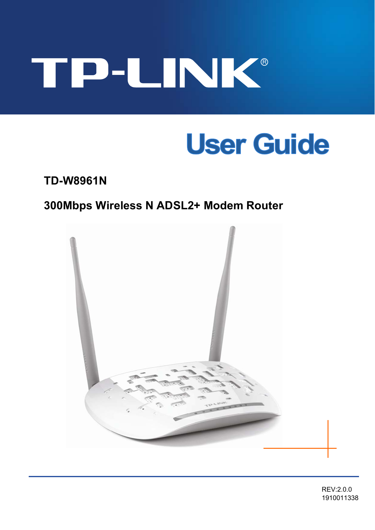
TP-Link Technologies Co., Ltd. 300Mbps Wireless N ADSL2+ Modem Router TD W8961N

Contents

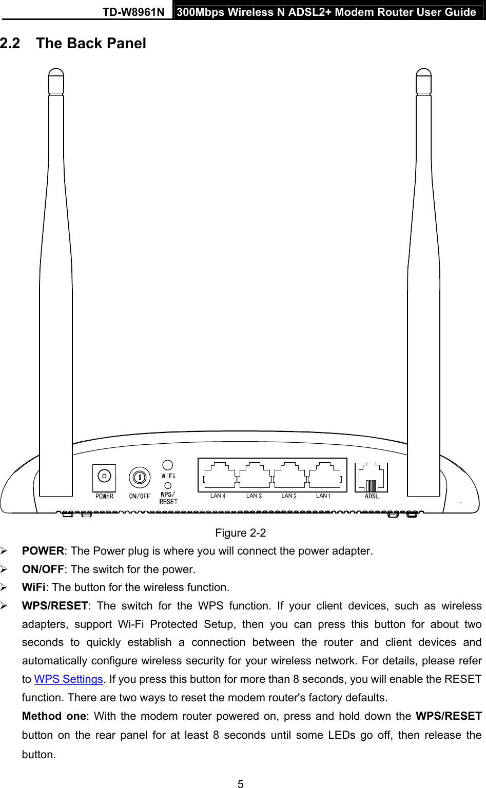
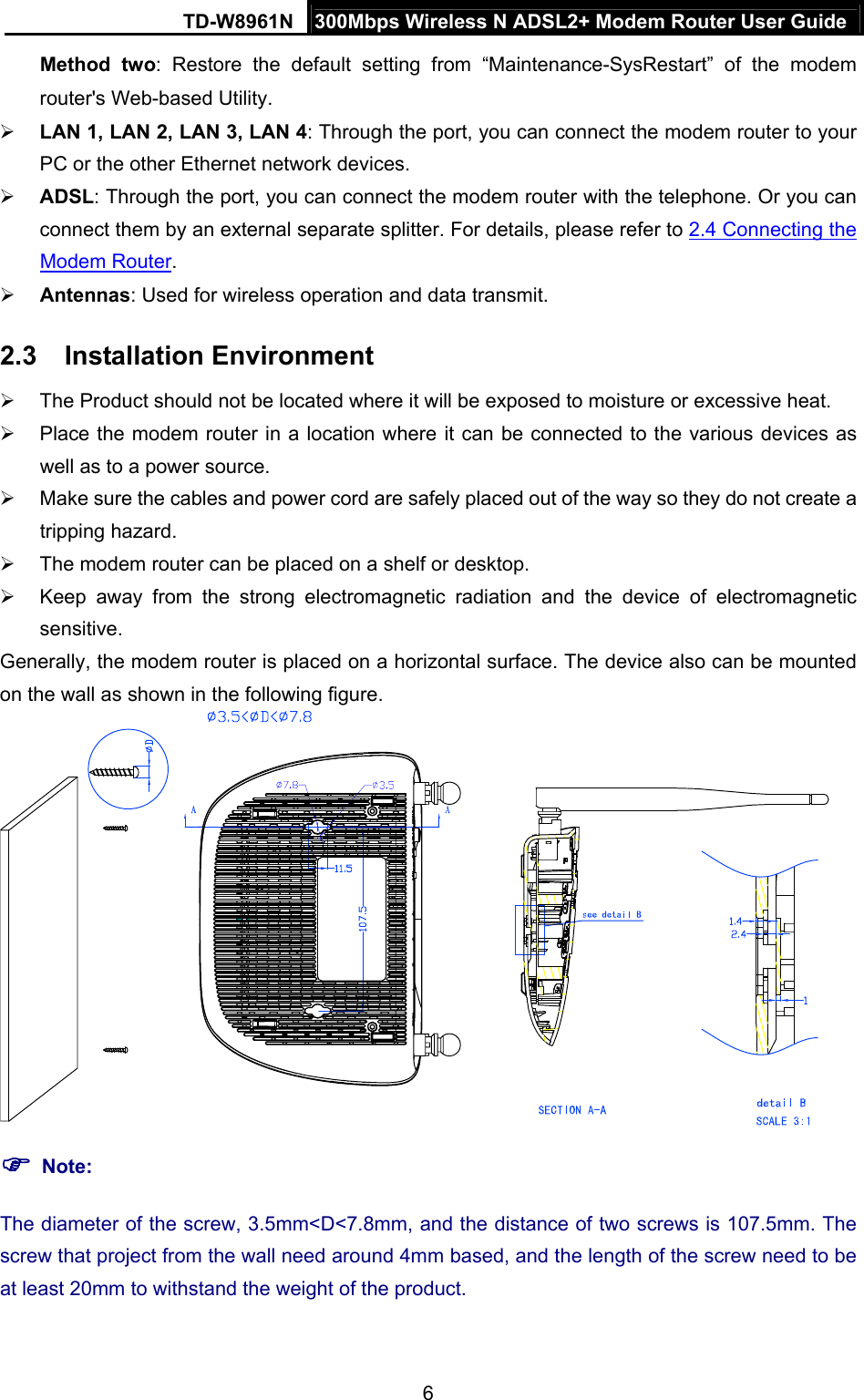
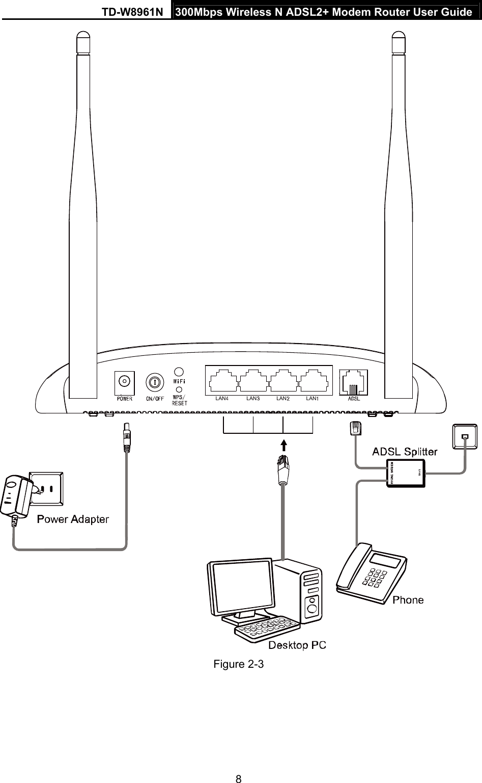
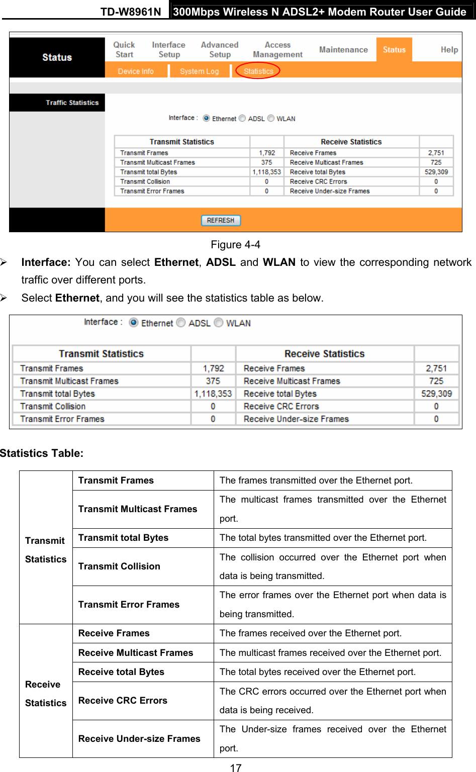
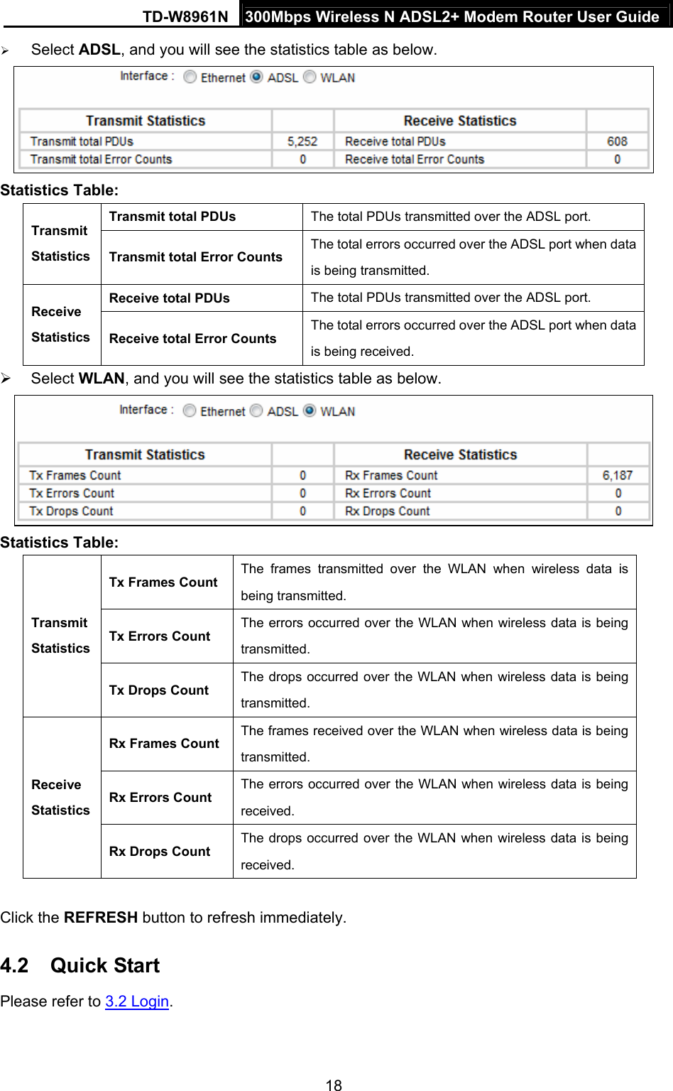
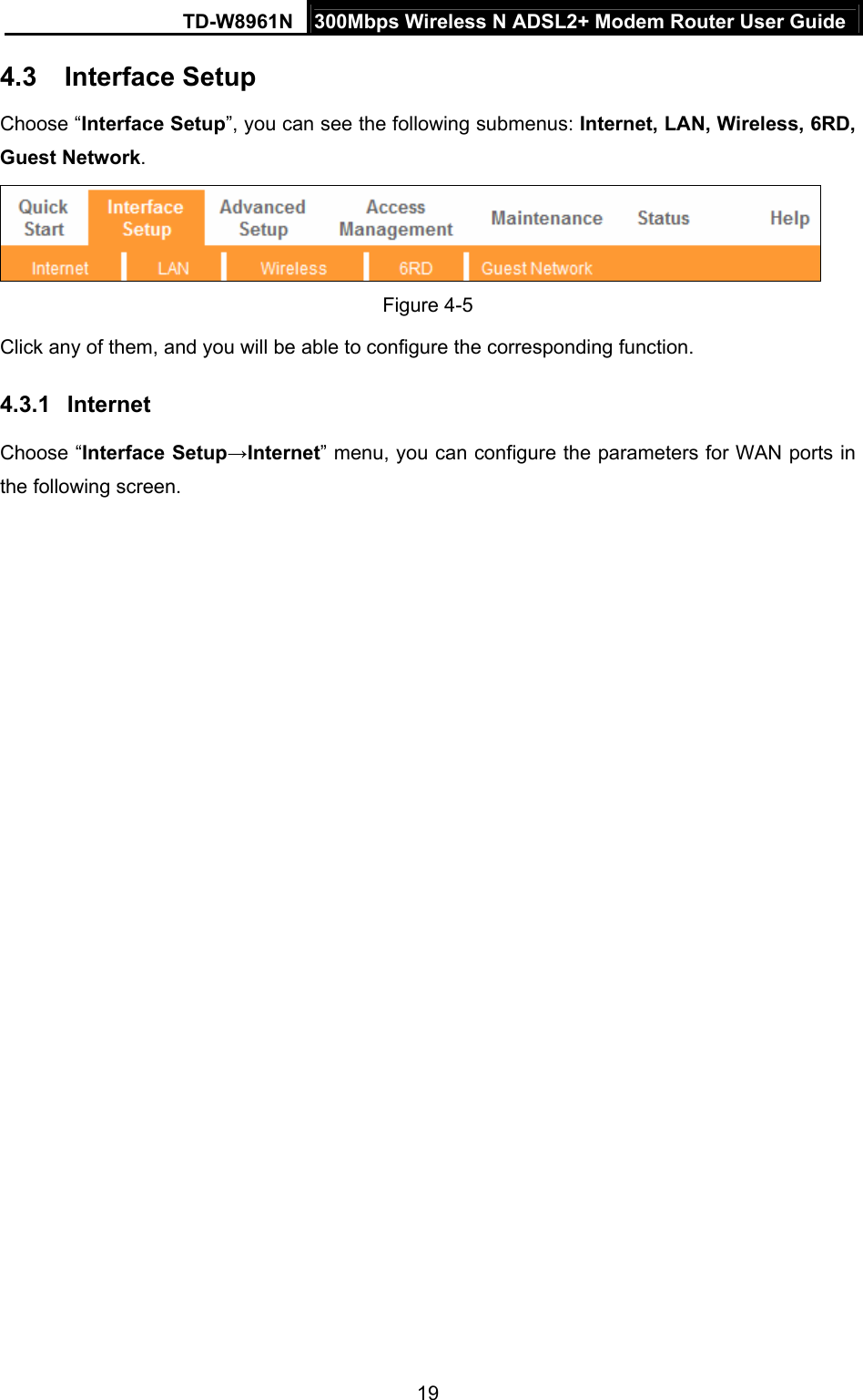
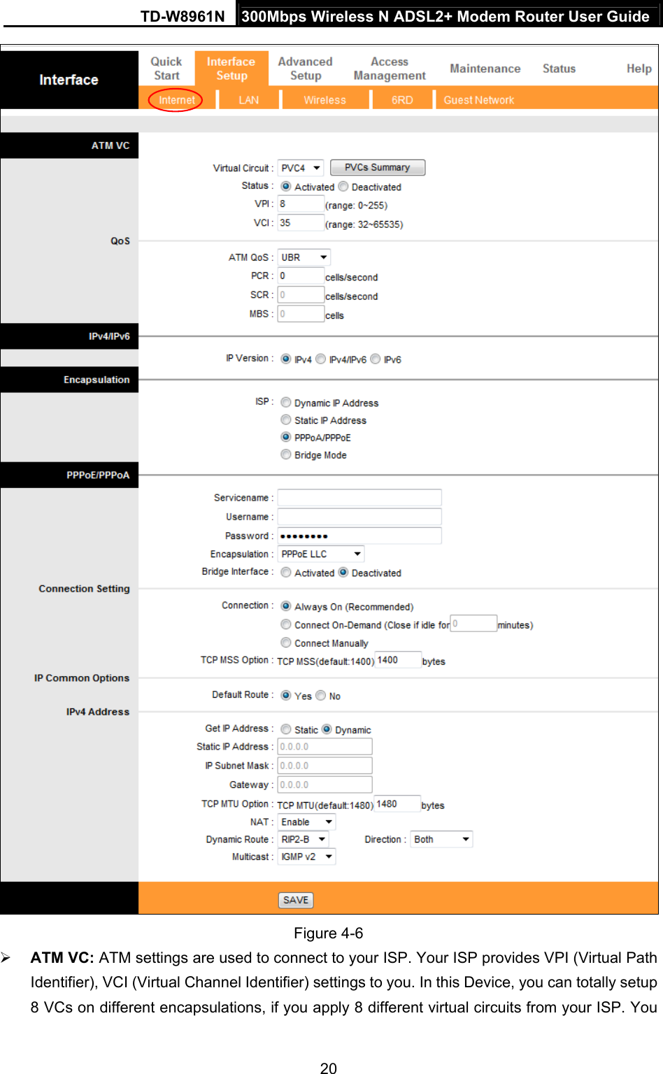
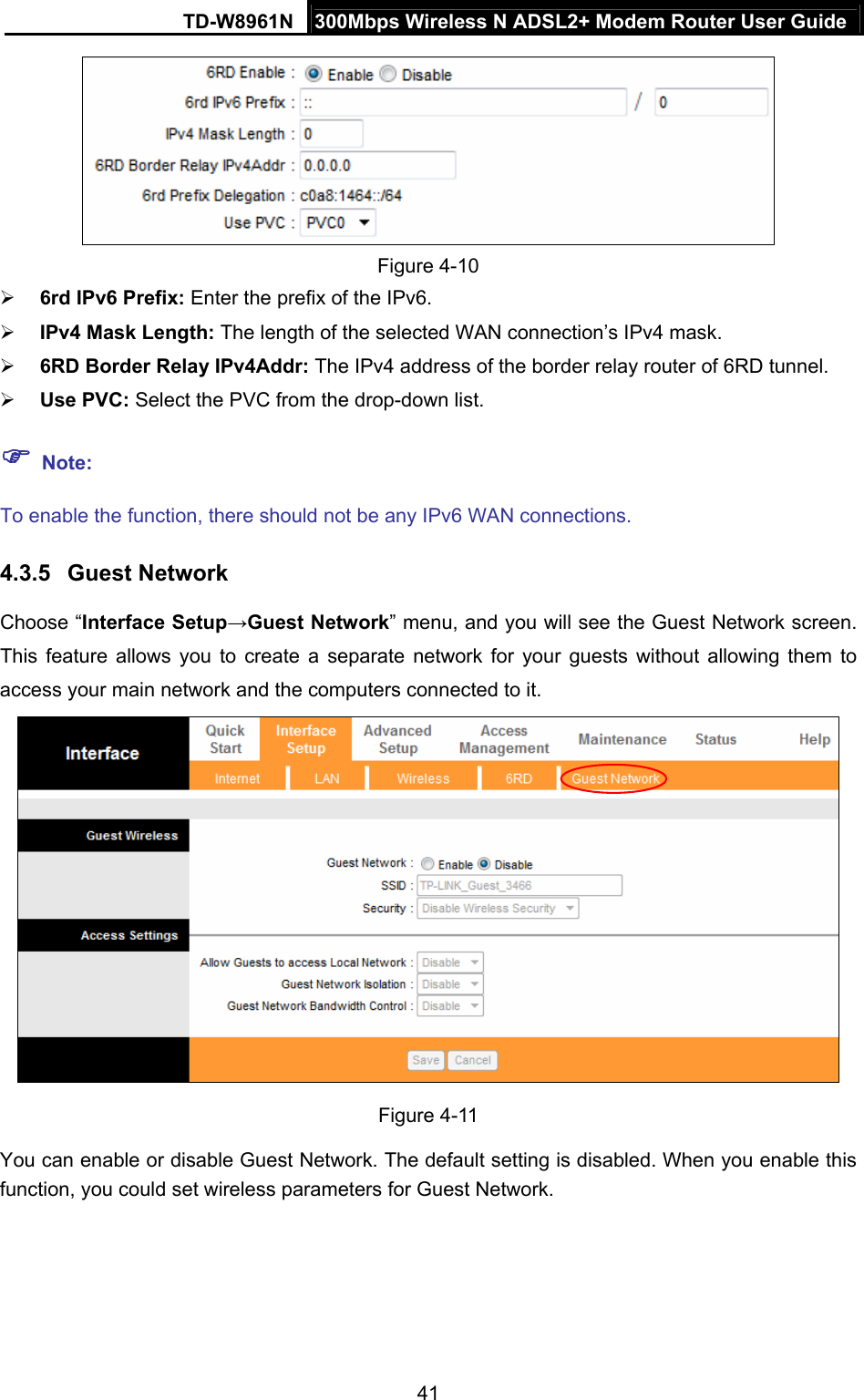
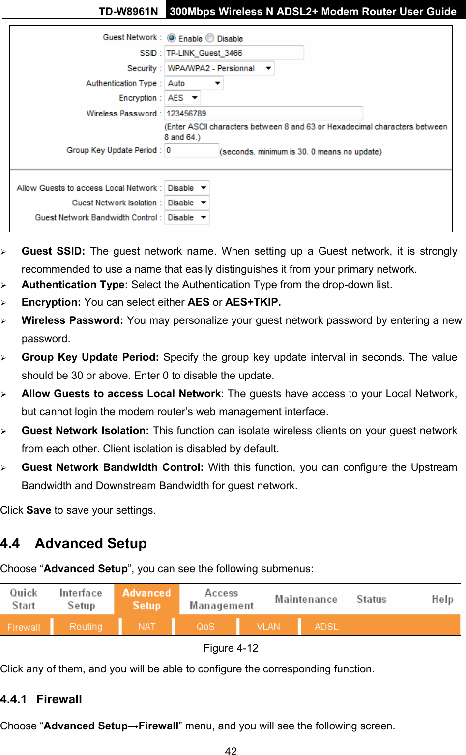
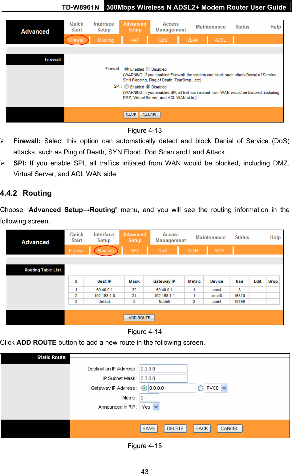
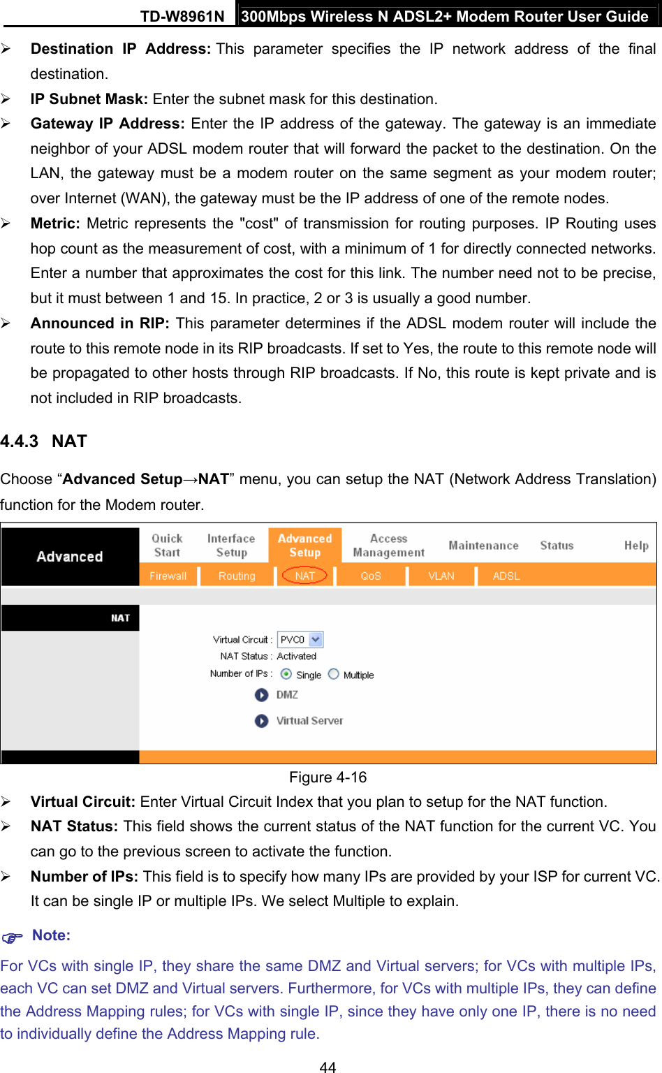
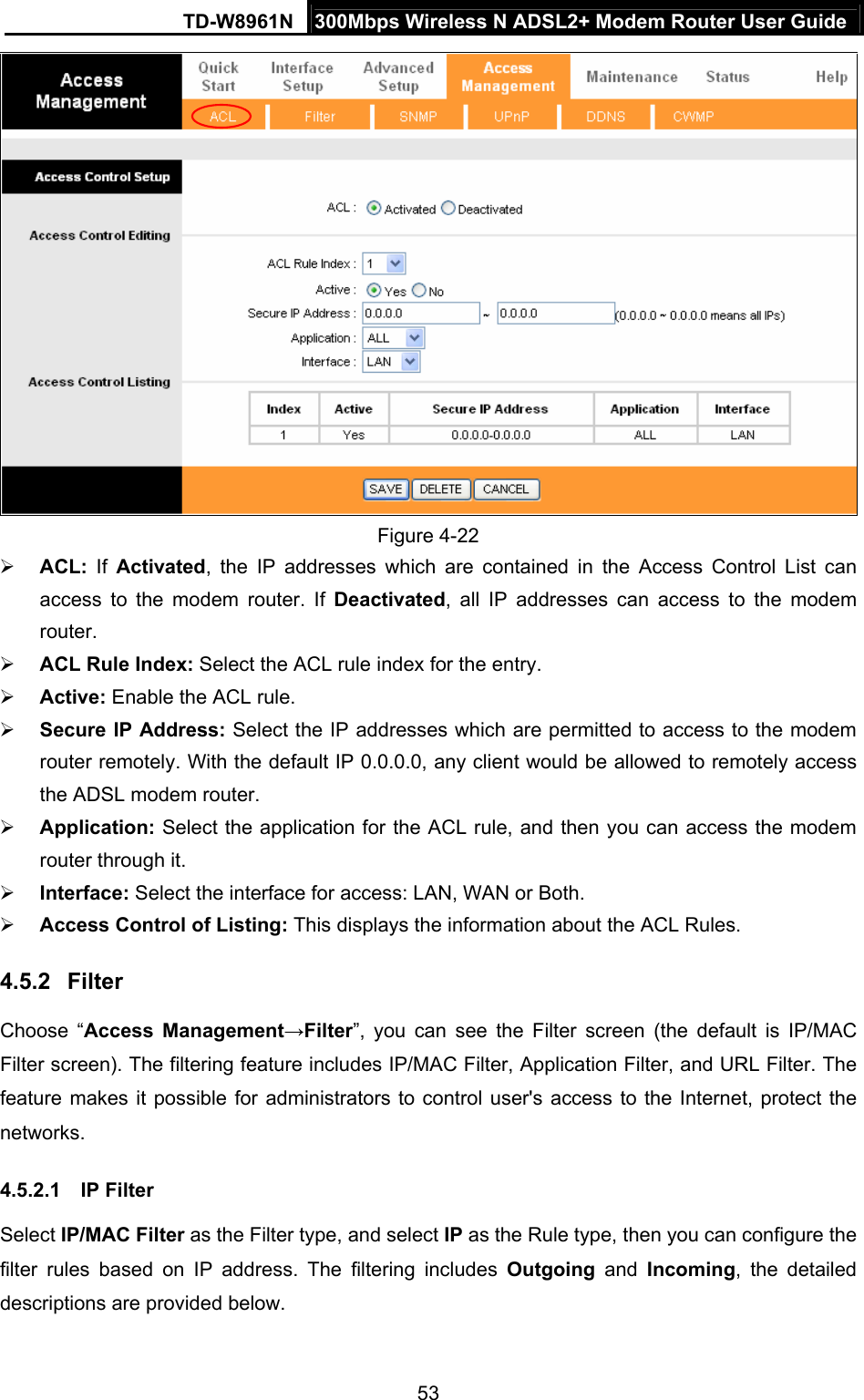
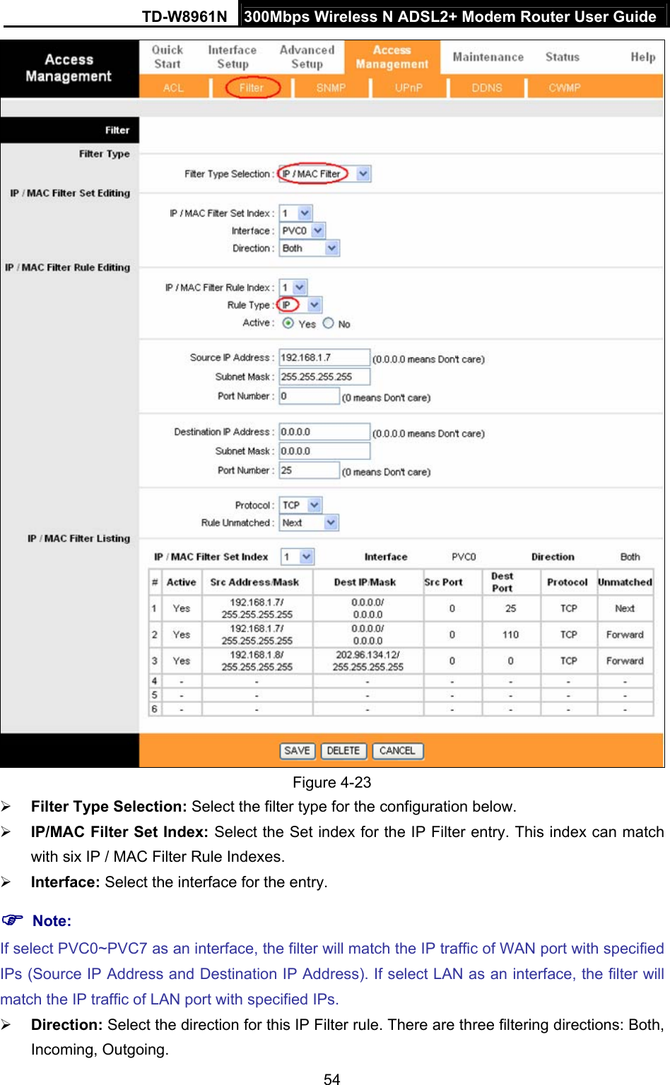
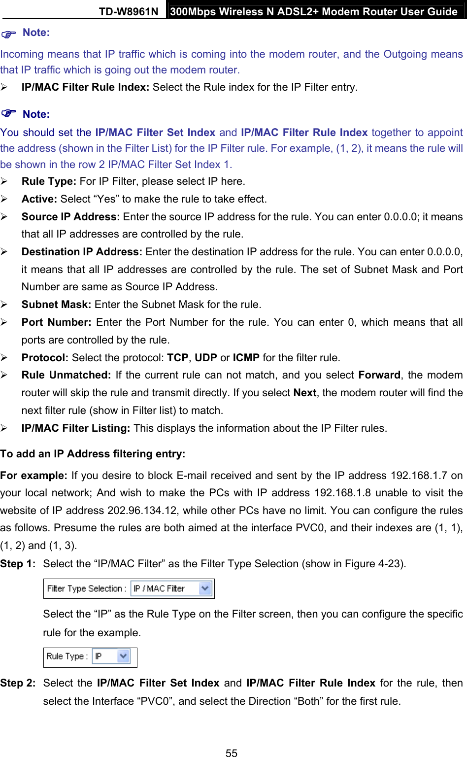
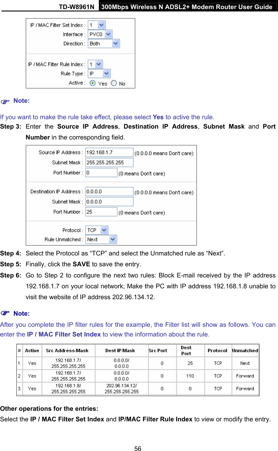
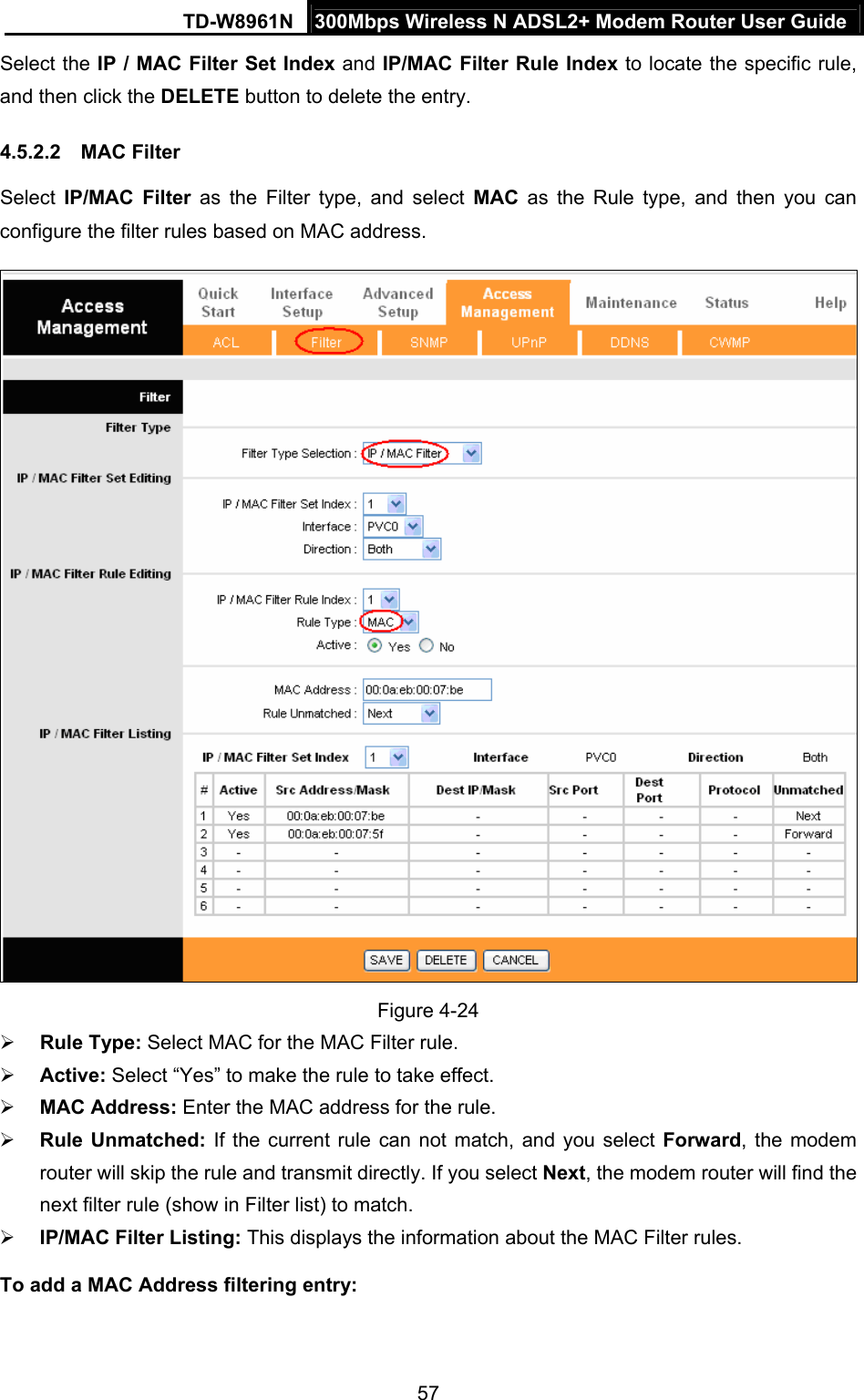
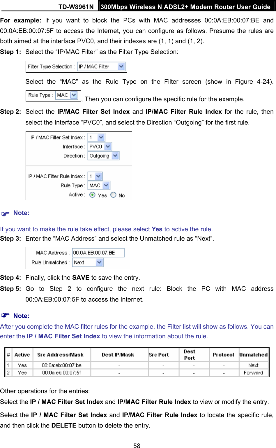
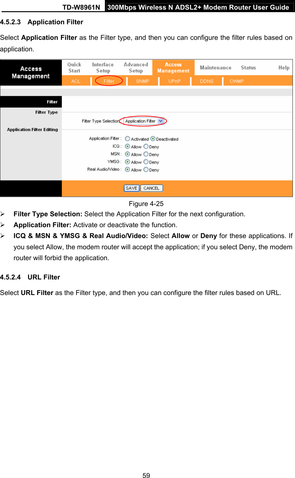
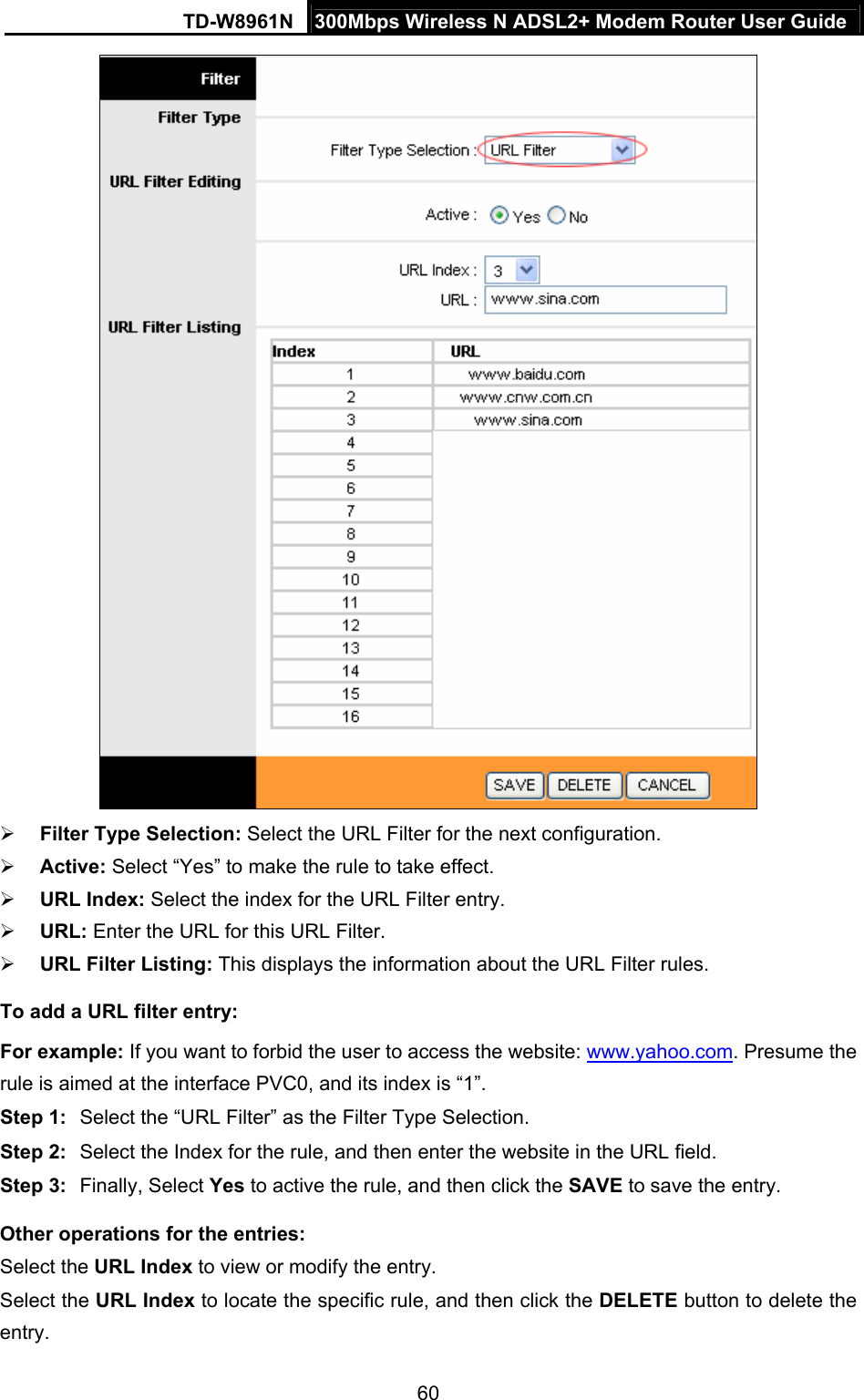
User Manual (TD-W8961N)

  TD-W8961N 300Mbps Wireless N ADSL2+ Modem Router  REV:2.0.0 1910011338
 COPYRIGHT & TRADEMARKS Specifications are subject to change without notice.    is a registered trademark of TP-LINK TECHNOLOGIES CO., LTD. Other brands and product names are trademarks or registered trademarks of their respective holders. No part of the specifications may be reproduced in any form or by any means or used to make any derivative such as translation, transformation, or adaptation without permission from TP-LINK TECHNOLOGIES CO., LTD. Copyright © 2015 TP-LINK TECHNOLOGIES CO., LTD. All rights reserved. http://www.tp-link.com
 FCC STATEMENT  This equipment has been tested and found to comply with the limits for a Class B digital device, pursuant to part 15 of the FCC Rules. These limits are designed to pro-vide reasonable protection against harmful interference in a residential installation. This equipment generates, uses and can radiate radio frequency energy and, if not in-stalled and used in accordance with the instructions, may cause harmful interference to radio communications. However, there is no guarantee that interference will not occur in a particular installation. If this equipment does cause harmful interference to radio or television reception, which can be determined by turning the equipment off and on, the user is encouraged to try to correct the interference by one or more of the following measures:   Reorient or relocate the receiving antenna.   Increase the separation between the equipment and receiver.   Connect the equipment into an outlet on a circuit different from that to which the receiver is connected.     Consult the dealer or an experienced radio/ TV technician for help. This device complies with part 15 of the FCC Rules. Operation is subject to the following two conditions: 1)  This device may not cause harmful interference. 2)  This device must accept any interference received, including interference that may cause undesired operation. Any changes or modifications not expressly approved by the party responsible for compliance could void the user’s authority to operate the equipment. Note: The manufacturer is not responsible for any radio or TV interference caused by unauthorized modifications to this equipment. Such modifications could void the user’s authority to operate the equipment. FCC RF Radiation Exposure Statement This equipment complies with FCC RF radiation exposure limits set forth for an uncontrolled environment. This device and its antenna must not be co-located or operating in conjunction with any other antenna or transmitter. “To comply with FCC RF exposure compliance requirements, this grant is applicable to only Mobile Configurations. The antennas used for this transmitter must be installed to provide a separation distance of at least 20 cm from all persons and must not be co-located or operating in conjunction with any other antenna or transmitter.”
 CE Mark Warning  This is a class B product. In a domestic environment, this product may cause radio interference, in Canadian Compliance Statement exempt RSS standard(s). Operation is subject erference, and   luding interference that may cause undesired me aux norms CNR exemptes de licence d’Industrie Canada. Le is celles susceptibles de provoquer un Industry Canada Statement cifications.  NMB-003 du Canada.   s all the du Règlement sur le Korea Warning Statements:  있음. NCC Notice & BSMI Notice 電波輻射性電機管理辦法 電機,非經許可,公司、商號或使用者均不得擅自變更頻航安全及干擾合法通行;經發現有干擾現象時,應立which case the user may be required to take adequate measures. This device complies with Industry Canada license-to the following two conditions:   (1) This device may not cause int(2)This device must accept any interference, incoperation of the device. Cet appareil est conforfonctionnement est soumis aux deux conditions suivantes:   (1) cet appareil ne doit pas provoquer d’interférences et   (2) cet appareil doit accepter toute interférence, y comprfonctionnement non souhaité de l’appareil. Complies with the Canadian ICES-003 Class B speCet appareil numérique de la classe B est conforme à la normeThis device complies with RSS 210 of Industry Canada. This Class B device meetrequirements of the Canadian interference-causing equipment regulations. Cet appareil numérique de la Classe B respecte toutes les exigences matériel brouilleur du Canada. 당해 무선설비는 운용중 전파혼신 가능성이注意!  依據 低功率第十二條 經型式認證合格之低功率射頻率、加大功率或變更原設計之特性或功能。 第十四條 低功率射頻電機之使用不得影響飛即停用,並改善至無干擾時方得繼續使用。前項合法通信,指依電信規定作業之無線電信。低功率
 射頻電機需忍受合法通信或工業、科學以及醫療用電波輻射性電機設備之干擾。 減少電磁波影響,請妥適使用。 安全諮詢及注意事項 ●請使用原裝電源供應器或只能按照本產品注明的電源類型使用本產品。 ●清潔本產品之前請先拔掉電源線。請勿使用液體、噴霧清潔劑或濕布進行清潔。 ●注意防潮,請勿將水或其他液體潑灑到本產品上。 ●插槽與開口供通風使用,以確保本產品的操作可靠並防止過熱,請勿堵塞或覆蓋開口。 ●請勿將本產品置放於靠近熱源的地方。除非有正常的通風,否則不可放在密閉位置中。  ●請不要私自打開機殼,不要嘗試自行維修本產品,請由授權的專業人士進行此項工作。 UkrSEPRO   Продукт сертифіковано згідно с правилами системи УкрСЕПРО на відповідність вимогам нормативних документів та вимогам,  що передбачені чинними законодавчими актами України.  Safety Information   When product has power button, the power button is one of the way to shut off the product; when there is no power button, the only way to completely shut off power is to disconnect the product or the power adapter from the power source.   Don’t disassemble the product, or make repairs yourself. You run the risk of electric shock and voiding the limited warranty. If you need service, please contact us.   Avoid water and wet locations. This product can be used in the following countries: AT BG BY CA CZ DE DK EE ES FI  FR GB GR HU IE  IT LT LV MT NL NO PL PT RO RU SE SK TR UA US
 TP-LINK TECHNOLOGIES CO., LTD  TP-LINK TECHNOLOGIES CO., LTD. Building 24 (floors 1, 3, 4, 5), and 28 (floors 1-4) Central Science and Technology Park, Shennan Rd, Nanshan, Shenzhen, China  DECLARATION OF CONFORMITY For the following equipment: Product Description: 300Mbps Wireless N ADSL2+ Modem Router Model No.: TD-W8961N Trademark: TP-LINK    We declare under our own responsibility that the above products satisfy all the technical regulations applicable to the product within the scope of Council Directives:     Directives 1999/5/EC, Directives 2004/108/EC, Directives 2006/95/EC, Directives 1999/519/EC, Directives 2011/65/EU The above product is in conformity with the following standards or other normative documents EN 300 328 V1.8.1     EN 301 489-1 V1.9.2 & EN 301 489-17 V2.2.1     EN 55022: 2010 + AC: 2011 EN 55024: 2010 EN 61000-3-2: 2006 + A1: 2009 + A2: 2009 EN 61000-3-3: 2013 EN 60950-1: 2006 + A11: 2009 + A1: 2010 + A12: 2011     EN 50385: 2002 The product carries the CE Mark:   Person responsible for making this declaration:  Yang Hongliang Product Manager of International Business   Date of issue: 2015  EN 60950-1: 2006 + A11: 2009 + A1: 2010 + A12: 2011+A2:2013
   CONTENTS Chapter 1Introduction ......................................................................................... 11.1Product Overview.................................................................................. 11.2Main Features ....................................................................................... 11.3Conventions .......................................................................................... 2Chapter 2Hardware Installation.......................................................................... 32.1The Front Panel .................................................................................... 32.2The Back Panel..................................................................................... 52.3Installation Environment........................................................................ 62.4Connecting the Modem Router ............................................................. 7Chapter 3Quick Installation Guide ..................................................................... 93.1TCP/IP Configuration ............................................................................ 93.2Login ................................................................................................... 10Chapter 4Software Configuration .................................................................... 144.1Status.................................................................................................. 144.1.1Device Info............................................................................................... 144.1.2System Log.............................................................................................. 154.1.3Statistics .................................................................................................. 164.2Quick Start .......................................................................................... 184.3Interface Setup.................................................................................... 194.3.1Internet .................................................................................................... 194.3.2LAN ......................................................................................................... 254.3.3Wireless................................................................................................... 304.3.46RD ......................................................................................................... 404.3.5Guest Network......................................................................................... 414.4Advanced Setup.................................................................................. 424.4.1Firewall .................................................................................................... 424.4.2Routing .................................................................................................... 434.4.3NAT ......................................................................................................... 444.4.4QoS ......................................................................................................... 474.4.5VLAN ....................................................................................................... 494.4.6ADSL ....................................................................................................... 514.5Access Management........................................................................... 524.5.1ACL ......................................................................................................... 52
   4.5.2Filter ........................................................................................................ 534.5.3SNMP ...................................................................................................... 614.5.4UPnP ....................................................................................................... 614.5.5DDNS ...................................................................................................... 624.5.6CWMP ..................................................................................................... 624.6Maintenance........................................................................................ 634.6.1Administration.......................................................................................... 634.6.2Time Zone ............................................................................................... 644.6.3Firmware.................................................................................................. 654.6.4SysRestart ............................................................................................... 674.6.5Diagnostics.............................................................................................. 684.7Help..................................................................................................... 68Appendix A: Specifications................................................................................... 70Appendix B: Configuring the PC........................................................................... 71Appendix C: Troubleshooting............................................................................... 75
TD-W8961N  300Mbps Wireless N ADSL2+ Modem Router User Guide 1  Chapter 1  Introduction Thank you for choosing the TD-W8961N 300Mbps Wireless N ADSL2+ Modem Router. 1.1  Product Overview The device is designed to provide a simple and cost-effective ADSL Internet connection for a private Ethernet or IEEE 802.11n/ IEEE 802.11g/ IEEE 802.11b wireless network. The TD-W8961N connects to an Ethernet LAN or computers via standard Ethernet ports. The ADSL connection is made using ordinary telephone line with standard connectors. Multiple workstations can be networked and connected to the Internet using a single Wide Area Network (WAN) interface and single global IP address. The advanced security enhancements, IP/MAC Filter,  Application Filter and URL Filter can help to protect your network from potentially devastating intrusions by malicious agents from the outside of your network. Quick Start of the Web-based Utility is supplied and friendly help messages are provided for the configuration. Network and Router management is done through the Web-based Utility which can be accessed through local Ethernet using any web browser. ADSL The TD-W8961N supports full-rate ADSL2+ connectivity conforming to the ITU and ANSI specifications. In addition to the basic DMT physical layer functions, the ADSL2+ PHY supports dual latency ADSL2+ framing (fast and interleaved) and the I.432 ATM Physical Layer. Wireless In the most attentive wireless security, the modem router provides multiple protection measures. It can be set to turn off the wireless network name (SSID) broadcast so that only stations that have the SSID can be connected. The modem router provides wireless LAN 64/128-bit WEP encryption security, WPA-PSK/WPA2-PSK authentication, as well as TKIP/AES encryption security. 1.2  Main Features   Four 10/100Mbps Auto-Negotiation RJ45 LAN ports (Auto MDI/MDIX), one RJ11 port.   Provides external splitter.   Adopts Advanced DMT modulation and demodulation technology.   Supports bridge mode and Router function.   Multi-user sharing a high-speed Internet connection.   Downstream data rates up to 24Mbps, upstream data rates up to 3.5Mbps (With Annex M enabled).   Supports long transfers, the max line length can reach to 6.5Km.   Supports remote configuration and management through SNMP and CWMP.
TD-W8961N  300Mbps Wireless N ADSL2+ Modem Router User Guide 2    Supports PPPoE, it allows connecting the internet on demand and disconnecting from the Internet when idle.   Provides reliable ESD and surge-protect function with quick response semi-conductive surge protection circuit.   High speed and asymmetrical data transmit mode, provides safe and exclusive bandwidth.   Supports All ADSL industrial standards.   Compatible with all mainstreams DSLAM (CO).   Provides integrated access of internet and route function which face to SOHO user.  Real-time Configuration and device monitoring.   Supports Multiple PVC (Permanent Virtual Circuit).   Built-in DHCP server.   Built-in firewall, supporting IP/MAC filter, Application filter and URL filter.   Supports Virtual Server, DMZ host and IP Address Mapping.   Supports Dynamic DNS, UPnP and Static Routing.   Supports system log and flow Statistics.   Supports firmware upgrade and Web management.   Provides WPA-PSK/WPA2-PSK data security, TKIP/AES encryption security.   Provides 64/128-bit WEP encryption security and wireless LAN ACL (Access Control List). 1.3  Conventions The modem router or device mentioned in this User Guide stands for TD-W8961N without any explanations. Parameters provided in the pictures are just references for setting up the product, which may differ from the actual situation.
TD-W8961N  300Mbps Wireless N ADSL2+ Modem Router User Guide 3  Chapter 2  Hardware Installation 2.1  The Front Panel  Figure 2-1 The LEDs locate on the front panel. They indicate the device’s working status. For details, please refer to LED Explanation. LED Explanation: Name  Status  Indication On  System initialization complete. Flash System initializing or firmware upgrading is in process. Do not disconnect or power off the modem router.  (Power) Off Power is off. On ADSL line is synchronized and ready to use. Flash The ADSL negotiation is in progress.  (ADSL) Off ADSL synchronization fails. Please refer to Note 1 for troubleshooting. On Internet connection is available.   Flash There is data being transmitted or received via the Internet.  (INTERNET) Off No Internet connection or the modem router is operating in Bridge mode. Please refer to Note 2 for troubleshooting. On The wireless function is enabled. Flash The modem router is sending or receiving data over the wireless network.  (Wireless) Off The wireless function is disabled. On A wireless device has been successfully added to the network by WPS function. Flash  A wireless device is trying to connect to the network via WPS. This process may take up to 4 minutes.  (WPS) Off The WPS function is disabled or the wireless device fails to be added to the network in 4 minutes after WPS function is enabled. Please refer to WPS Settings for more information.
TD-W8961N  300Mbps Wireless N ADSL2+ Modem Router User Guide 4  Name  Status  Indication On The corresponding LAN port is connected. Flash The modem router is sending or receiving data over this LAN port.  (LAN1-4) Off The corresponding LAN port is not connected.  Note: 1.  If the ADSL LED is off, please check your Internet connection first. Refer to 2.4 Connecting the Router for more information about how to make Internet connection correctly. If you have already made a right connection, please contact your ISP to make sure if your Internet service is available now. 2.  If the Internet LED is off, please check your ADSL LED first. If your ADSL LED is also off, please refer to Note 1. If your ADSL LED is on, please check your Internet configuration. You may need to check this part of information with your ISP and make sure everything have been input correctly. Refer to 4.1.1 Device Info and 4.3.1 Internet for more information.
TD-W8961N  300Mbps Wireless N ADSL2+ Modem Router User Guide 5  2.2  The Back Panel LAN LAN LAN LAN Figure 2-2  POWER: The Power plug is where you will connect the power adapter.  ON/OFF: The switch for the power.  WiFi: The button for the wireless function.    WPS/RESET: The switch for the WPS function. If your client devices, such as wireless adapters, support Wi-Fi Protected Setup, then you can press this button for about two seconds to quickly establish a connection between the router and client devices and automatically configure wireless security for your wireless network. For details, please refer to WPS Settings. If you press this button for more than 8 seconds, you will enable the RESET function. There are two ways to reset the modem router's factory defaults.   Method one: With the modem router powered on, press and hold down the WPS/RESET button on the rear panel for at least 8 seconds until some LEDs go off, then release the button.
TD-W8961N  300Mbps Wireless N ADSL2+ Modem Router User Guide 6  Method two: Restore the default setting from “Maintenance-SysRestart” of the modem router's Web-based Utility.  LAN 1, LAN 2, LAN 3, LAN 4: Through the port, you can connect the modem router to your PC or the other Ethernet network devices.  ADSL: Through the port, you can connect the modem router with the telephone. Or you can connect them by an external separate splitter. For details, please refer to 2.4 Connecting the Modem Router.   Antennas: Used for wireless operation and data transmit. 2.3  Installation Environment   The Product should not be located where it will be exposed to moisture or excessive heat.   Place the modem router in a location where it can be connected to the various devices as well as to a power source.   Make sure the cables and power cord are safely placed out of the way so they do not create a tripping hazard.   The modem router can be placed on a shelf or desktop.   Keep away from the strong electromagnetic radiation and the device of electromagnetic sensitive. Generally, the modem router is placed on a horizontal surface. The device also can be mounted on the wall as shown in the following figure.   Note: The diameter of the screw, 3.5mm<D<7.8mm, and the distance of two screws is 107.5mm. The screw that project from the wall need around 4mm based, and the length of the screw need to be at least 20mm to withstand the weight of the product.
TD-W8961N  300Mbps Wireless N ADSL2+ Modem Router User Guide 7  2.4  Connecting the Modem Router Before installing the device, please make sure your broadband service provided by your ISP is available. If there is any problem, please contact your ISP. Before cable connection, cut off the power supply and keep your hands dry. You can follow the steps below to install it. Step 1:  Connect the ADSL Line. Method one: Plug one end of the twisted-pair ADSL cable into the ADSL port on the rear panel of TD-W8961N, and insert the other end into the wall socket. Method two:You can use a separate splitter. External splitter can divide the data and voice, and then you can access the Internet and make calls at the same time. The external splitter has three ports: • LINE: Connect to the wall jack • PHONE: Connect to the phone sets • MODEM: Connect to the ADSL port of TD-W8961N Plug one end of the twisted-pair ADSL cable into the ADSL port on the rear panel of TD-W8961N. Connect the other end to the MODEM port of the external splitter. Step 2:  Connect the Ethernet cable. Attach one end of a network cable to your computer’s Ethernet port or a regular hub/switch port, and the other end to the LAN port on the TD-W8961N. Step 3:  Power on the computers and LAN devices. Step 4:  Attach the power adapter. Connect the power adapter to the power connector on the rear of the device and plug in the adapter to an electrical outlet or power extension. The electrical outlet shall be installed near the device and shall be easily accessible.
TD-W8961N  300Mbps Wireless N ADSL2+ Modem Router User Guide 8  LAN LAN LAN LAN Figure 2-3
TD-W8961N  300Mbps Wireless N ADSL2+ Modem Router User Guide 9  Chapter 3  Quick Installation Guide This chapter will show you how to configure the basic functions of your TD-W8961N 300Mbps Wireless N ADSL2+ Modem Router using Quick Setup Wizard within minutes. 3.1  TCP/IP Configuration The default IP address of the TD-W8961N 300Mbps Wireless N ADSL2+ Modem Router is 192.168.1.1. And the default Subnet Mask is 255.255.255.0. These values can be changed as you desire. In this guide, we use all the default values for description. Connect the local PC to the LAN/WAN port of the Modem Router. Configure your PC to obtain IP address automatically in the following way.  Obtain an IP address automatically 1)  Set up the TCP/IP Protocol in "Obtain an IP address automatically" mode on your PC. If you need instructions as to how to do this, please refer to Appendix B: "Configuring the PC”. 2)  Then the built-in DHCP server will assign IP address for the PC. Now, you can run the Ping command in the command prompt to verify the network connection. Please click the Start menu on your desktop, select run tab, type cmd or command in the field and press Enter. Type ping 192.168.1.1 on the following screen, and then press Enter. If the result displayed is similar to the screen below, the connection between your PC and the router has been established.  Figure 3-1 If the result displayed is similar to the screen shown below, it means that your PC has not connected to the router.
TD-W8961N  300Mbps Wireless N ADSL2+ Modem Router User Guide 10   Figure 3-2 You can check it by following the steps below: 1)  Is the connection between your PC and the router correct? The LEDs of LAN port which you link to the device and the LEDs on your PC's adapter should be lit. 2)  Is the TCP/IP configuration for your PC correct? If the router's IP address is 192.168.1.1, your PC's IP address must be within the range of 192.168.1.2 ~ 192.168.1.254. 3.2  Login Once your host PC is properly configured, please proceed as following instructions to use the Web-based Utility: Launch your web browser and enter http://tplinkmodem.net or 192.168.1.1 in the address bar.   After that, you will see the screen shown as below, enter the default User Name admin and the default Password admin, and then click Login button to access to the Quick Start screen.  Figure 3-3
TD-W8961N  300Mbps Wireless N ADSL2+ Modem Router User Guide 11  Step 1:  Click the NEXT button.  Figure 3-4 Step 2:  Configure the time zone for the modem router, and then click the NEXT button.  Figure 3-5
TD-W8961N  300Mbps Wireless N ADSL2+ Modem Router User Guide 12  Step 3:  Select your country and ISP, and select your ISP Connection type (Here we take PPPoE/PPPoA mode for example), and complete the corresponding settings with the information provided by your ISP, then click the NEXT button.  Figure 3-6  Note: Per FCC regulations, all Wi-Fi products marketed in the U.S. must be fixed to the U.S. region only.
TD-W8961N  300Mbps Wireless N ADSL2+ Modem Router User Guide 13  Step 4:  Configure the rules for the Wlan, and click the NEXT button.  Figure 3-7  Note: If the Access Point is activated, the wireless function will be available even without the external antenna because of an additional printed antenna. To adopt the wireless security protection measures, please refer to section 4.3.3. Step 5:  Click SAVE to finish the Quick Start.  Figure 3-8
TD-W8961N  300Mbps Wireless N ADSL2+ Modem Router User Guide 14  Chapter 4  Software Configuration This User Guide recommends using the “Quick Installation Guide” for first-time installation. For advanced users, if you want to know more about this device and make use of its functions adequately, maybe you will get help from this chapter to configure the advanced settings through the Web-based Utility. After your successful login, you can configure and manage the device. There are main menus on the top of the Web-based Utility; submenus will be available after you click one of the main menus. On the center of the Web-based Utility, there are the detailed configurations or status information. To apply any settings you have altered on the page, please click the SAVE button. 4.1  Status Choose “Status”, you can see the following submenus: Device Info, System Log and Statistics. Click any of them, and you will be able to configure the corresponding function.  Figure 4-1 Click any of them, and you will be able to view the corresponding information. 4.1.1  Device Info Choose “Status→Device Info” menu, and you will be able to view the device information, including LAN, WAN and ADSL. The information will vary depending on the settings of the modem router configured on the Interface Setup screen.
TD-W8961N  300Mbps Wireless N ADSL2+ Modem Router User Guide 15    Figure 4-2 4.1.2  System Log Choose “Status→System Log” menu, and you will be able to query the logs of the modem router.
TD-W8961N  300Mbps Wireless N ADSL2+ Modem Router User Guide 16   Figure 4-3 The modem router can keep logs of all traffic. You can query the logs to find what happened to the modem router. Click the CLEAR LOG button to clear the logs. Click the SAVE LOG button to save the logs. 4.1.3  Statistics Choose “Status→Statistics” menu, and you will be able to view the network traffic over Ethernet, ADSL and WLAN.
TD-W8961N  300Mbps Wireless N ADSL2+ Modem Router User Guide 17   Figure 4-4  Interface:  You can select Ethernet, ADSL and WLAN to view the corresponding network traffic over different ports.    Select Ethernet, and you will see the statistics table as below.  Statistics Table: Transmit Frames  The frames transmitted over the Ethernet port. Transmit Multicast Frames The multicast frames transmitted over the Ethernet port. Transmit total Bytes  The total bytes transmitted over the Ethernet port. Transmit Collision The collision occurred over the Ethernet port when data is being transmitted. Transmit Statistics Transmit Error Frames The error frames over the Ethernet port when data is being transmitted.   Receive Frames  The frames received over the Ethernet port. Receive Multicast Frames  The multicast frames received over the Ethernet port. Receive total Bytes  The total bytes received over the Ethernet port. Receive CRC Errors The CRC errors occurred over the Ethernet port when data is being received. Receive Statistics Receive Under-size Frames The Under-size frames received over the Ethernet port.
TD-W8961N  300Mbps Wireless N ADSL2+ Modem Router User Guide 18   Select ADSL, and you will see the statistics table as below.  Statistics Table: Transmit total PDUs  The total PDUs transmitted over the ADSL port. Transmit Statistics Transmit total Error Counts The total errors occurred over the ADSL port when data is being transmitted. Receive total PDUs  The total PDUs transmitted over the ADSL port. Receive Statistics Receive total Error Counts The total errors occurred over the ADSL port when data is being received.  Select WLAN, and you will see the statistics table as below.  Statistics Table: Tx Frames Count The frames transmitted over the WLAN when wireless data is being transmitted. Tx Errors Count The errors occurred over the WLAN when wireless data is being transmitted. Transmit Statistics Tx Drops Count The drops occurred over the WLAN when wireless data is being transmitted. Rx Frames Count The frames received over the WLAN when wireless data is being transmitted. Rx Errors Count The errors occurred over the WLAN when wireless data is being received. Receive Statistics Rx Drops Count The drops occurred over the WLAN when wireless data is being received.  Click the REFRESH button to refresh immediately. 4.2  Quick Start Please refer to 3.2 Login.
TD-W8961N  300Mbps Wireless N ADSL2+ Modem Router User Guide 19  4.3  Interface Setup Choose “Interface Setup”, you can see the following submenus: Internet, LAN, Wireless, 6RD, Guest Network.   Figure 4-5 Click any of them, and you will be able to configure the corresponding function. 4.3.1  Internet Choose “Interface Setup→Internet” menu, you can configure the parameters for WAN ports in the following screen.
TD-W8961N  300Mbps Wireless N ADSL2+ Modem Router User Guide 20   Figure 4-6  ATM VC: ATM settings are used to connect to your ISP. Your ISP provides VPI (Virtual Path Identifier), VCI (Virtual Channel Identifier) settings to you. In this Device, you can totally setup 8 VCs on different encapsulations, if you apply 8 different virtual circuits from your ISP. You
TD-W8961N  300Mbps Wireless N ADSL2+ Modem Router User Guide 21  need to activate the VC to take effect. For PVCs management, you can use ATM QoS to setup each PVC traffic line's priority.  Virtual Circuit: Select the VC number you want to setup, PVC0~PVC7.  PVCs Summary: Click the button, and you can view the summary information about the PVCs.  Status: If you want to use a designed VC, you should activate it.  VPI: Identifies the virtual path between endpoints in an ATM network. The valid range is from 0 to 255. Please input the value provided by your ISP.  VCI: Identifies the virtual channel endpoints in an ATM network. The valid range is from 32 to 65535 (1 to 31 is reserved for well-known protocols). Please input the value provided by your ISP.  QoS: Select the Quality of Service types for this Virtual Circuit, including CBR (Constant Bit Rate), UBR (Unspecified Bit Rate) and VBR (Variable Bit Rate). These QoS types are all controlled by the parameters specified below, including PCR (Peak Cell Rate), SCR (Sustained Cell Rate) and MBS (Maximum Burst Size), please configure them according to your needs.  IPv4/IPv6: Select the version of IP.  Encapsulation:  There are four connection types: Dynamic IP Address, Static IP Address, PPPoA/PPPoE and Bridge Mode. Please choose the designed type that you want to use. After that, you should follow the configuration below to proceed. 1) Dynamic IP Address Select this option if your ISP provides you an IP address automatically. This option is typically used for Cable services. Please enter the Dynamic IP information accordingly.     Encapsulation: Select the encapsulation mode for the Dynamic IP Address, you can leave it default.
TD-W8961N  300Mbps Wireless N ADSL2+ Modem Router User Guide 22   Default Route: If enable this function, the current PVC will be considered as the default gateway to internet from this device.  TCP MTU Option: Enter the TCP MTU as your desire.  NAT: Select this option to Enable/Disable the NAT (Network Address Translation) function for this VC. The NAT function can be activated or deactivated per PVC basis.  Dynamic Route: Select this option to specify the RIP (Routing Information protocol) version for WAN interface, including RIP1, RIP2-B and RIP2-M. RIP2-B and RIP2-M are both sent in RIP2 format, the difference is that RIP2-M using Multicast, while RIP2-B using Broadcast format.   Direction:  Select this option to specify the RIP direction. None is for disabling the RIP function. Both means the ADSL modem router will periodically send routing information and accept routing information, and then incorporate them into routing table. IN only means the ADSL modem router will only accept but will not send RIP packet. OUT only means the ADSL modem router will only send but will not accept RIP packet.  Multicast:  Select IGMP version, or disable the function. IGMP (Internet Group Multicast Protocol) is a session-layer protocol used to establish membership in a multicast group. The ADSL ATU-R supports both IGMP version 1 (IGMP v1) and IGMP v2. Select “Disabled” to disable it. 2)  Static IP Address Select this option if your ISP provides static IP information to you. You should set static IP address, IP subnet mask, and gateway address in the screen below.
TD-W8961N  300Mbps Wireless N ADSL2+ Modem Router User Guide 23    Note: Each IP address entered in the fields must be in the appropriate IP form, which is four IP octets separated by a dot (x.x.x.x), such as 192.168.1.100. The modem router will not accept the IP address if it is not in this format. 3) PPPoA/PPPoE Select this option if your ISP requires you to use a PPPoE connection. This option is typically used for DSL services. Select Dynamic PPPoE to obtain an IP address automatically for your PPPoE connection. Select Static PPPoE to use a static IP address for your PPPoE connection. Please enter the information accordingly.
TD-W8961N  300Mbps Wireless N ADSL2+ Modem Router User Guide 24    Servicename: Enter a name to mark current connection, or you can leave it blank.  Username: Enter your username for your PPPoA/PPPoE connection.  Password: Enter your password for your PPPoA/PPPoE connection.  Encapsulation:  For both PPPoA/PPPoE connection, you need to specify the type of Multiplexing, either LLC or VC Mux.  Bridge Interface: Activate the option, and the modem router can also work in Bridge mode.  Connection: For PPPoA/PPPoE connection, you can select Always on or Connect on-Demand or Connect Manually. Connect on demand is dependent on the traffic. If there is no traffic (or Idle) for a pre-specified period of time), the connection will tear down automatically. And once there is traffic send or receive, the connection will be automatically on.  Default Route: You should select Yes to configure the PVC as the default gateway to internet from this device.  Get IP Address: Select Static or Dynamic. For PPPoA/PPPoE connection, you need to specify the public IP address for this ADSL modem router. The IP address can be either dynamically (via DHCP) or given IP address provided by your ISP. For Static IP, you need to specify the IP address, Subnet Mask and Gateway IP address. 4) Bridge Mode
TD-W8961N  300Mbps Wireless N ADSL2+ Modem Router User Guide 25  If you select this type of connection, the modem can be configured to act as a bridging device between your LAN and your ISP. Bridges are devices that enable two or more networks to communicate as if they are two segments of the same physical LAN.     Note: After you finish the Internet configuration, please click SAVE to make the settings take effect. 4.3.2  LAN Choose “Interface Setup→LAN” menu, and you will see the LAN screen. Please configure the parameters for LAN ports according to the descriptions below.
TD-W8961N  300Mbps Wireless N ADSL2+ Modem Router User Guide 26    Figure 4-7  Router Local IP: These are the IP settings of the LAN interface for the device. These settings may be referred to as Private settings. You may change the LAN IP address if needed. The LAN IP address is private to your internal network and cannot be seen on the Internet.  IP Address: Enter the modem router’s local IP Address, then you can access to the Web-based Utility via the IP Address, the default value is 192.168.1.1.  IP Subnet Mask: Enter the modem router’s Subnet Mask, the default value is 255.255.255.0.  Dynamic Route: Select this option to specify the RIP (Routing Information protocol) version for LAN interface, including RIP1, RIP2-B and RIP2-M. RIP2-B and RIP2-M are both sent in RIP2 format, the difference is that RIP2-M using Multicast, while RIP2-B using Broadcast format.
TD-W8961N  300Mbps Wireless N ADSL2+ Modem Router User Guide 27   Direction: Select this option to specify the RIP direction. None is for disabling the RIP function. Both means the ADSL modem router will periodically send routing information and accept routing information, and then incorporate them into routing table. IN only means the ADSL modem router will only accept but will not send RIP packet. OUT only means the ADSL modem router will only send but will not accept RIP packet.  Multicast: Select IGMP version, or disable the function. IGMP (Internet Group Multicast Protocol) is a session-layer protocol used to establish membership in a multicast group. The ADSL ATU-R supports both IGMP version 1 (IGMP v1)  IGMP v2 and IGMP v3. Select “Disabled” to disable it.  IGMP Snoop: Enable the IGMP Snoop function if you need.  Mld Snoop: Enable the Mld Snoop function if you need.  DHCP: Select Enabled, then you will see the screen below. The modem router will work as a DHCP Server; it becomes the default gateway for DHCP client connected to it. DHCP stands for Dynamic Host Control Protocol. The DHCP Server gives out IP addresses when a device is booting up and request an IP address to be logged on to the network. That device must be set as a DHCP client to obtain the IP address automatically. By default, the DHCP Server is enabled. The DHCP address pool contains the range of the IP address that will automatically be assigned to the clients on the network.
TD-W8961N  300Mbps Wireless N ADSL2+ Modem Router User Guide 28    Starting IP Address: Enter the starting IP address for the DHCP server's IP assignment. Because the default IP address for the modem router is 192.168.1.1, the default Start IP Address is 192.168.1.100.  IP Pool Count: The max user pool size.  Lease Time: The length of time for the IP lease. After the dynamic IP address has expired, the user will be automatically assigned a new dynamic IP address. The default is 259200 seconds.  Physical Ports: If a physical port is unchecked, the client connected to that port will not be able to obtain IP address automatically although the DHCP function is enabled. All the ports are checked by default.  DHCP Table: The information of the DHCP clients will be displayed here
TD-W8961N  300Mbps Wireless N ADSL2+ Modem Router User Guide 29    Hostname: Display the name of the DHCP client.    IP Address: Display the IP Address of the DHCP client.  MAC Address: Display the MAC Address of the DHCP client.    Status:  Display the status of the assigned IP Address, either Static or Auto.  Static indicates that the IP Address is bounded to the MAC Address, while Auto indicates that the IP Address is assigned to the MAC Address automatically. How to assign a static IP address to the client? 1). Select an IP Address from the drop-down list. 2). Enter the MAC Address of the client in the table.  DNS Relay: If you want to disable this feature, you just need to set both Primary and secondary DNS IP to 0.0.0.0. If you want to use DNS relay, you can setup DNS server IP to 192.168.1.1 on their Computer. If not, the device will perform as no DNS relay.  Primary DNS Server: Type in your preferred DNS server.  Secondary DNS Server: Type in your preferred DNS server.  Note: If  Use Auto Discovered DNS Server Only is selected in DNS Relay, this modem router will accept the first received DNS assignment from one of the PPPoA, PPPoE or MER/DHCP enabled PVC(s) during the connection establishment. If Use User Discovered DNS Server Only is selected in DNS Relay, it is necessary for you to enter the primary and optional secondary DNS server IP addresses. After type in the address, click SAVE button to save it and invoke it.    DHCP Relay: Select Relay, then you will see the following screen, and the modem router will work as a DHCP Relay. A DHCP relay is a computer that forwards DHCP data between computers that request IP addresses and the DHCP server that assigns the addresses. Each of the device's interfaces can be configured as a DHCP relay. If it is enabled, the DHCP requests from local PCs will forward to the DHCP server runs on WAN side. To have this function working properly, please run on router mode only, disable the DHCP server on the LAN port, and make sure the routing table has the correct routing entry.   DHCP Server IP for Relay Agent: Enter the DHCP server IP Address runs on WAN side.
TD-W8961N  300Mbps Wireless N ADSL2+ Modem Router User Guide 30   Note: If you select Disabled, the DHCP function will not take effect. 4.3.3  Wireless Choose “Interface Setup→Wireless” menu, and you will see the Wireless screen. Please configure the parameters for wireless according to the descriptions below.
TD-W8961N  300Mbps Wireless N ADSL2+ Modem Router User Guide 31   Figure 4-8
TD-W8961N  300Mbps Wireless N ADSL2+ Modem Router User Guide 32   Access point Settings: These are the settings of the access point. You can configure the rules to allow wireless-equipped computers and other devices to communicate with a wireless network.  Access point: Select Activated to allow wireless station to associate with the access point.  Channel: Select the channel you want to use from the drop-down List of Channel. This field determines which operating frequency will be used. It is not necessary to change the wireless channel unless you notice interference problems with another nearby access point.  Note: Per FCC regulations, all Wi-Fi products marketed in the U.S. must be fixed to the U.S. region only.  Transmit Power: Here you can specify the transmit power of modem router. You can select High, Medium or Low which you would like. High is the default setting and is recommended.  Beacon Interval: Enter a value between 20-1000 milliseconds. The Beacon Interval value indicates the frequency interval of the beacon. A beacon is a packet broadcast by the modem router to synchronize the wireless network. The default value is 100.  RTS/CTS Threshold: Should you encounter inconsistent data flow, only minor reduction of the default value 2347 is recommended. If a network packet is smaller than the preset RTS threshold size, the RTS/CTS mechanism will not be enabled. The modem router sends Request to Send (RTS) frames to a particular receiving station and negotiates the sending of a data frame. After receiving an RTS, the wireless station responds with a Clear to Send (CTS) frame to acknowledge the right to begin transmission. In most cases, keep its default value of 2347.  Fragmentation Threshold: This value specifies the maximum size for a packet before data is fragmented into multiple packets. If you experience a high packet error rate, you may slightly increase the Fragmentation Threshold. Setting the Fragmentation Threshold too low may result in poor network performance. Only minor reduction of the default value is recommended. In most cases, it should remain at its default value of 2346.  DTIM:  This value, between 1 and 255, indicates the interval of the Delivery Traffic Indication Message (DTIM). A DTIM field is a countdown field informing clients of the next window for listening to broadcast and multicast messages. When the modem router has buffered broadcast or multicast messages for associated clients, it sends the next DTIM with a DTIM Interval value. Its clients hear the beacons and awaken to receive the broadcast and multicast messages. The default value is 1.  Wireless Mode: In the drop-down list you can select “802.11b”, “802.11g”, “802.11n”, “802.11b+g”, “802.11g+n” and “802.11b+g+n”. “802.11b+g+n” allows both 802.11b, 802.11g and 802.11n wireless stations to connect to the modem router.
TD-W8961N  300Mbps Wireless N ADSL2+ Modem Router User Guide 33   11n Settings: These are the settings of the 11n parameters. If “802.11n”, “802.11g+n” or “802.11b+g+n” is selected for Wireless mode, these settings will be displayed.  Channel Bandwidth: Select the Bandwidth you want to use from the drop-down List. There are two options, “20 MHz” and “20/40 MHz”. If bigger bandwidth is selected, device could transmit and receive data with higher speed.  Extension Channel: If “20/40 MHz” is selected, this option will be displayed.  Guard Interval: Select the guard interval you want from the drop-down list.  MCS:  Select the wireless transmission rate from the drop-down list. By default, the option is AUTO.  DOT 11N Spec Settings: These are the settings of the DOT 11N Spec.  Ht OpMode: HT operation mode.  Enable Auto BA: Enable or disable auto block ack setion with peer.  Enable BA Decline: Enable or disable decline block ack to peer.  Enable TX A-MSDU: Enable or disable AMSDU section.  STBC: Enable or disable HT STBC support.  Enable HtProtect: Enable or disable HT protect.  Disallow TKP: Enable or disable 11n rate with 11n AP when cipher is TKIP or WEP.  Multiple SSIDs Settings: These are the settings of the SSID.  SSID Index: The index of the SSID, and in this model, you can only leave it as a default value of 1.  Broadcast SSID: When wireless clients survey the local area for wireless networks to associate with, they will detect the SSID broadcast by the modem router. To broadcast the modem router’s SSID, keep the default setting. If you don’t want to broadcast the modem router’s SSID, select “No”.  Use WPS: Use WPS (Wi-Fi Protected Setup) function, you can add a new wireless device to an existing network quickly. To Use WPS, keep the default setting, and configure the parameters in WPS Settings. If you don’t want to Use WPS, select “No”.  WPS Settings: WPS can help you to add a new wireless device to an existing network quickly. This section will guide you how to use WPS function.  WPS state: Display the current WPS state.  WPS mode: If the wireless adapter supports Wi-Fi Protected Setup (WPS), you can establish a wireless connection between wireless adapter and modem router using either PIN method or Push Button Configuration (PBC) method, please select the one you want. 1) PIN code If the wireless adapter supports Wi-Fi Protected Setup and the PIN method, you can add it to the network by PIN with the following two methods. Select PIN code, you will see the following screen.
TD-W8961N  300Mbps Wireless N ADSL2+ Modem Router User Guide 34   Method One: Enter the PIN into my modem router Step 1:  For the configuration of the wireless adapter, please choose “Enter the PIN of this device into my access point or wireless router” in the configuration utility, and get the PIN code on the screen as below, then click Connect.    The WPS Configuration Screen of Wireless Adapter Step 2:  For the modem router, keep PIN code selected and enter the PIN code of the wireless adapter in the field next to enrollee PIN code as shown below. Then click Start WPS.
TD-W8961N  300Mbps Wireless N ADSL2+ Modem Router User Guide 35   Method Two: Enter the PIN from your Router or AP device Step 1:  Get the Current PIN code of your modem router from AP self PIN code (each modem router has its unique PIN code. Here takes the PIN code 11930624 of this modem router for example).    Step 2:  For the configuration of the wireless adapter, please choose “Enter the PIN of my access point or wireless router” in the configuration utility, and enter the PIN code of the modem router into the field next to “PIN”. Then click Connect.
TD-W8961N  300Mbps Wireless N ADSL2+ Modem Router User Guide 36   The WPS Configuration Screen of Wireless Adapter  Note: The default PIN code of the modem router can be found in its label or the WPS screen in its web configuration page. 2) PBC If the wireless adapter supports Wi-Fi Protected Setup and the Push Button Configuration (PBC) method, you can add it to the network by PBC with the following two methods. Select PBC, you will see the following screen.  Method One: Step 1:  Press the WPS/RESET button on your modem router for about 2 seconds or click the Start WPS button on the screen.
TD-W8961N  300Mbps Wireless N ADSL2+ Modem Router User Guide 37  LAN LAN LAN LAN Step 2:  Press and hold the WPS button of the adapter directly for about 2 seconds.  Step 3:  Wait until the following screen appears. Click OK to complete the WPS configuration.  The WPS Configuration Screen of Wireless Adapter   Method Two: Step 1:  Press the WPS/RESET button on your modem router for about 2 seconds or click Start WPS button on the screen. LAN LAN LAN LAN Step 2:  For the configuration of the wireless adapter, please choose “Push the button on my access point or wireless router” in the configuration utility as below, and click Connect.
TD-W8961N  300Mbps Wireless N ADSL2+ Modem Router User Guide 38   The WPS Configuration Screen of Wireless Adapter Step 3:  Wait for a while until the following screen appears. Click OK to complete the WPS configuration.  The WPS Configuration Screen of Wireless Adapter    WPS progress: Show the current WPS progress.  Reset to OOB: Reset WPS AP to the OOB(out-of-box) configuration.  SSID: Wireless network name shared among all points in a wireless network. The SSID must be identical for all devices in the wireless network. It is case-sensitive and must not exceed 32 characters (use any of the characters on the keyboard). Make sure this setting is the same for all stations in your wireless network. Type the desired SSID in the space provided.  Authentication Type: Select an authentication type from the drop-down list, which allows you to configure security features of the wireless LAN interface. Options available
TD-W8961N  300Mbps Wireless N ADSL2+ Modem Router User Guide 39  are: Disabled, WEP-64Bits, WEP-128Bits, WPA-PSK, WPA2-PSK, and WPA-PSK/ WPA2-PSK.  1) WEP- 64Bits To configure WEP-64Bits settings, select the WEP-64Bits option from the drop-down list. The menu will change to offer the appropriate settings. WEP-64Bits is a data privacy mechanism based on a 64-bit shared key algorithm, as described in the IEEE 802.11g standard. 2) WEP-128Bits To configure WEP-128Bits settings, select the WEP-128Bits option from the drop-down list. The menu will change to offer the appropriate settings. 128-bit is stronger than 64-bit. 3) WPA-PSK To configure WPA-PSK settings, select the WPA-PSK option from the drop-down list. The menu will change to offer the appropriate settings. WPA-PSK requires a shared key and does not use a separate server for authentication. PSK keys can be ASCII or Hex type.  Encryption: Select the encryption you want to use: TKIP/AES, TKIP or AES (AES is an encryption method stronger than TKIP).  TKIP (Temporal Key Integrity Protocol) - a wireless encryption protocol that provides dynamic encryption keys for each packet transmitted.  AES (Advanced  Encryption  Standard) - A security method that uses symmetric 128-bit block data encryption.  Pre-Shared Key: Enter the key shared by the modem router and your other network devices. It must have 8-63 ASCII characters or 64 Hexadecimal digits. 4) WPA2-PSK To configure WPA2-PSK settings, select the WPA2-PSK option from the drop-down list. The menu will change to offer the appropriate settings. WPA2-PSK requires a shared key and does not use a separate server for authentication. PSK keys can be ASCII or Hex type. 5) WPA-PSK/WPA2-PSK To configure WPA-PSK/WPA2-PSK settings, select the WPA-PSK/WPA2-PSK option from the drop-down list. The menu will change to offer the appropriate settings. WPA-PSK/WPA2-PSK requires a shared key and does not use a separate server for authentication. PSK keys can be ASCII or Hex type. WPA-PSK/WPA2-PSK is more flexible than WPA-PSK or WPA2-PSK.  WDS Settings: With this function enabled, the modem router can bridge two or more WLANs.  WDS Mode: Select On/Off to enable/disable WDS.  MAC Address: Enter the MAC Address you wish to bridge in the field.
TD-W8961N  300Mbps Wireless N ADSL2+ Modem Router User Guide 40   Wireless MAC Address Filter: Wireless access can be filtered by using the MAC addresses of the wireless devices transmitting within your network’s RADIUS.    Active: If you wish to filter users by MAC Address, select “Activated”, and “Deactived” for don’t.  Action: To filter wireless users by MAC Address, select “Allow Association” or “Deny Association” the follow Wireless LAN station(s) association.  MAC Address: Enter the MAC Address you wish to filter in the field.  Note: For most users, it is recommended to use the default Wireless LAN Performance settings. Any changes made to these settings may adversely affect your wireless network. Under certain circumstances, changes may benefit performance. Carefully consider and evaluate any changes to these wireless settings. 4.3.4  6RD IPv6 tunnel is a kind of transition mechanism to enable IPv6-only hosts to reach IPv4 services and to allow isolated IPv6 hosts and networks to reach each-other over IPv4-only infrastructure before IPv6 completely supplants IPv4. It is a temporary solution for networks that do not support native dual-stack, where both IPv6 and IPv4 run independently. As a type of IPv6 tunnel, 6RD is used in the situation that your WAN connection is IPv4 while LAN connection is IPv6. Choose “Interface Setup→6RD” menu.    Figure 4-9  6RD Enable: The default setting is disabled, select Enable when your WAN connection is IPv4 while LAN connection is IPv6.
TD-W8961N  300Mbps Wireless N ADSL2+ Modem Router User Guide 41   Figure 4-10  6rd IPv6 Prefix: Enter the prefix of the IPv6.  IPv4 Mask Length: The length of the selected WAN connection’s IPv4 mask.  6RD Border Relay IPv4Addr: The IPv4 address of the border relay router of 6RD tunnel.  Use PVC: Select the PVC from the drop-down list.  Note: To enable the function, there should not be any IPv6 WAN connections. 4.3.5  Guest Network Choose “Interface Setup→Guest Network” menu, and you will see the Guest Network screen. This feature allows you to create a separate network for your guests without allowing them to access your main network and the computers connected to it.   Figure 4-11 You can enable or disable Guest Network. The default setting is disabled. When you enable this function, you could set wireless parameters for Guest Network.
TD-W8961N  300Mbps Wireless N ADSL2+ Modem Router User Guide 42    Guest SSID: The guest network name. When setting up a Guest network, it is strongly recommended to use a name that easily distinguishes it from your primary network.    Authentication Type: Select the Authentication Type from the drop-down list.  Encryption: You can select either AES or AES+TKIP.  Wireless Password: You may personalize your guest network password by entering a new password.  Group Key Update Period: Specify the group key update interval in seconds. The value should be 30 or above. Enter 0 to disable the update.  Allow Guests to access Local Network: The guests have access to your Local Network, but cannot login the modem router’s web management interface.  Guest Network Isolation: This function can isolate wireless clients on your guest network from each other. Client isolation is disabled by default.    Guest Network Bandwidth Control: With this function, you can configure the Upstream Bandwidth and Downstream Bandwidth for guest network. Click Save to save your settings. 4.4  Advanced Setup Choose “Advanced Setup”, you can see the following submenus:  Figure 4-12 Click any of them, and you will be able to configure the corresponding function. 4.4.1  Firewall Choose “Advanced Setup→Firewall” menu, and you will see the following screen.
TD-W8961N  300Mbps Wireless N ADSL2+ Modem Router User Guide 43   Figure 4-13  Firewall:  Select this option can automatically detect and block Denial of Service (DoS) attacks, such as Ping of Death, SYN Flood, Port Scan and Land Attack.  SPI:  If you enable SPI, all traffics initiated from WAN would be blocked, including DMZ, Virtual Server, and ACL WAN side. 4.4.2  Routing Choose “Advanced Setup→Routing” menu, and you will see the routing information in the following screen.  Figure 4-14 Click ADD ROUTE button to add a new route in the following screen.  Figure 4-15
TD-W8961N  300Mbps Wireless N ADSL2+ Modem Router User Guide 44   Destination IP Address: This parameter specifies the IP network address of the final destination.  IP Subnet Mask: Enter the subnet mask for this destination.  Gateway IP Address: Enter the IP address of the gateway. The gateway is an immediate neighbor of your ADSL modem router that will forward the packet to the destination. On the LAN, the gateway must be a modem router on the same segment as your modem router; over Internet (WAN), the gateway must be the IP address of one of the remote nodes.  Metric:  Metric represents the "cost" of transmission for routing purposes. IP Routing uses hop count as the measurement of cost, with a minimum of 1 for directly connected networks. Enter a number that approximates the cost for this link. The number need not to be precise, but it must between 1 and 15. In practice, 2 or 3 is usually a good number.  Announced in RIP: This parameter determines if the ADSL modem router will include the route to this remote node in its RIP broadcasts. If set to Yes, the route to this remote node will be propagated to other hosts through RIP broadcasts. If No, this route is kept private and is not included in RIP broadcasts. 4.4.3  NAT Choose “Advanced Setup→NAT” menu, you can setup the NAT (Network Address Translation) function for the Modem router.  Figure 4-16  Virtual Circuit: Enter Virtual Circuit Index that you plan to setup for the NAT function.  NAT Status: This field shows the current status of the NAT function for the current VC. You can go to the previous screen to activate the function.  Number of IPs: This field is to specify how many IPs are provided by your ISP for current VC. It can be single IP or multiple IPs. We select Multiple to explain.  Note: For VCs with single IP, they share the same DMZ and Virtual servers; for VCs with multiple IPs, each VC can set DMZ and Virtual servers. Furthermore, for VCs with multiple IPs, they can define the Address Mapping rules; for VCs with single IP, since they have only one IP, there is no need to individually define the Address Mapping rule.
TD-W8961N  300Mbps Wireless N ADSL2+ Modem Router User Guide 45  4.4.3.1  DMZ Choose “Advanced Setup→NAT→DMZ”, you can configure the DMZ host in the following screen. A DMZ (demilitarized zone) is a host between a private local network and the outside public network. It prevents outside users from getting direct access to a server that has company data. Users of the public network outside the company can access to the DMZ host.  Figure 4-17  DMZ Host IP Address: Enter the specified IP Address for DMZ host on the LAN side. 4.4.3.2  Virtual Server Choose “Advanced Setup→NAT→Virtual Server” in Figure 4-16, you can configure the Virtual Server in the following screen.   The Virtual Server is the server or server(s) behind NAT (on the LAN), for example, Web server or FTP server, that you can make visible to the outside world even though NAT makes your whole inside network appear as a single machine to the outside world.   Rule Index: The Virtual server rule index for this VC. You can specify 10 rules in maximum. All the VCs with single IP will use the same Virtual Server rules.  Application: The Virtual servers can be used for setting up public services on your LAN.  Protocol: The protocol used for this application.  Start & End port number: Enter the specific Start and End Port number you want to forward. If it is one port only, you can enter the End port number the same as Start port number. For example, if you want to set the FTP Virtual server, you can set the start and end port number to 21.
TD-W8961N  300Mbps Wireless N ADSL2+ Modem Router User Guide 46   Local IP Address: Enter the IP Address for the Virtual Server in LAN side.  Virtual Server Listing: This displays the information about the Virtual Servers you establish. To add a virtual server entry:   Step 1:  Select the “Virtual Circuit” and select “Virtual Server”.  Note: For VCs with single IP, select Single; For VCs with multiple IPs, select Multiple for the option. Step 2:  Select the Rule index for the rule. Step 3:  Select the application you want from drop-down list, then the protocol and port number will be added to the corresponding field automatically, you only need to configure the IP address for the virtual server; If the application list does not contain the service that you want, please configure the Port number, IP Address and Protocol manually. Step 4:  After that, click SAVE to make the entry take effect. Other operations for the entries: Enter the index of assigned entry, and click the DELETE button to delete the entry. Click the BACK button to return to the previous screen. Click the CANCEL button to cancel the configuration which is made just now. 4.4.3.3  IP Address Mapping Select  Multiple for numbers of IPs in Figure 4-16, and choose “Advanced Setup→NAT→IP Address Mapping(for Multiple IP Service)”. You can configure the Address Mapping Rule in the following screen. The IP Address Mapping is for those VCs that configured with multiple IPs. The IP Address Mapping rule is per-VC based (only for Multiple IPs' VCs).   Rule Index: Select the Virtual server rule index for this VC. You can specify 8 rules in maximum.   Rule Typ: There are four types: one-to-one, Many-to-One, Many-to-Many Overload and Many-to-Many No-overload.  Local Start & End IP: Enter the local IP Address you plan to map to. Local Start IP is the starting local IP address and Local End IP is the ending local IP address. If the rule is for all local IPs, then the Start IP is 0.0.0.0 and the End IP is 255.255.255.255.
TD-W8961N  300Mbps Wireless N ADSL2+ Modem Router User Guide 47   Public Start & End IP: Enter the public IP Address you want to do NAT. Public Start IP is the starting public IP address and Public End IP is the ending public IP address. If you have a dynamic IP, enter 0.0.0.0 as the Public Start IP.  Address Mapping List: This displays the information about the Mapping addresses. To add a mapping rule:   Step 1:  Select the “Virtual Circuit” and Multiple for the “Number of IPs”. Then select the tab IP Address Mapping.  Note: IP Address Mapping is only available for VCs with Multiple IPs. Step 2:  Select the Rule index for the rule. Step 3:  Select the rule type you want from the drop-down list. Step 4:  Enter the local and public IP addresses in the corresponding fields. Step 5:  After that, click SAVE to make the entry take effect. Other operations for the entries: Select the index of assigned entry, and click the DELETE button to delete the entry. Click the BACK button to return to the previous screen. Click the CANCEL button to cancel the configuration which is made just now. 4.4.4  QoS Choose “Advanced Setup→QoS”, you can configure the QoS in the following screen. QoS helps to prioritize data as it enters your modem router. By attaching special identification marks or headers to incoming packets, QoS determines which queue the packets enter, based priority. This is useful when there are certain types of data you want to give higher priority, such as voice data packets give higher priority than Web data packets. This option will provide better service of selected network traffic over various technologies.
TD-W8961N  300Mbps Wireless N ADSL2+ Modem Router User Guide 48   Figure 4-18  IP Version:Select your IP version.  QoS: Select this option to Activate/Deactivate the IP QoS on different types (IP ToS and DiffServ).  Summary: Click the button to view the configurations of QoS.  Rule: Configure the rules for QoS. If the traffic complies with the rule, then the modem router will take the corresponding action to deal with it.  Rule Index: Select the index for the rule you want to configure.  Active: Activate the rule. The rule can take effect only when it is activated.  Application: Select the application that the rule aimed at.  Physical Ports: Select the port whose traffic flow are controlled by the rule.
TD-W8961N  300Mbps Wireless N ADSL2+ Modem Router User Guide 49   Destination MAC & IP & Mask & Port Range: Enter the IP information about the Destination host for the rule.  Source MAC & IP & Mask & Port Range: Enter the IP information about the Source host for the rule.  Protocol ID: Select one among TCP/UDP, TCP, UDP or ICMP protocols for the application.  Vlan ID Range: Enter the Vlan range, and the rule will be effective to the selected Vlans.  IPP/DS Field: Select the type of the action to assign the priority. When you select IPP/TOS, you can assign the priority via IP information. IP QoS function is intended to deliver guaranteed as well as differentiated Internet services by giving network resource and usage control to the Network operator.  IP Precedence Range: Enter the IP precedence range that the modem router takes to differentiate the traffic.  Type of Service: Select the type of service that the modem router takes to deal with the traffic.  802.1p: Select the priority range for the rule. When you select DSCP, you can assign the priority via DHCP (the header of IP group). It maps the IP group into corresponding service class.  DSCP Range: Enter the DSCP range to differentiate the traffic.  802.1p: Select the priority range for the rule.  Action: Configure the action that the modem router takes to deal with the traffic which accord with the rule.  IPP/DS Field: Select the type for the action.  IP Precedence Remarking: Select the number to remark the priority for IP precedence.  Type of Service Remarking: Select the type to remark the service.  DSCP Remarking: Enter the number to remark the DSCP priority.  802.1p Remarking: Select the type to remark the 802.1p priority.  Queue: Select the priority type for the action. 4.4.5  VLAN Choose “Advanced Setup→VLAN”, you can activate the VLAN function in the following screen. Virtual LAN (VLAN) is a group of devices on one or more LANs that are configured so that they can communicate as if they were attached to the same LAN, when in fact they are located on a number of different LAN segments. Because VLANs are based on logical instead of physical connections, it is very flexible for user/host management, bandwidth allocation and resource optimization. There are two types of VLAN as follows: Port-Based VLAN: Each physical switch port is configured with an access list specifying membership in a set of VLANs. ATM VLAN: Using LAN Emulation (LANE) protocol to map Ethernet packets into ATM cells and deliver them to their destination by converting an Ethernet MAC address into an ATM address.
TD-W8961N  300Mbps Wireless N ADSL2+ Modem Router User Guide 50   Figure 4-19 1)  Define VLAN Group   Click Define VLAN Group, you can define VLAN groups in the following screen.   VLAN Index: Select the VLAN index for this VC. You can specify 8 groups in maximum.  VLAN ID: This indicates the VLAN group.  ATM VCs: Select the ATM VCs as members of VLAN, and if you leave the Tagged blank, the tag in frames will be deleted when transmitted from the VC.  Ethernet: Select the Ethernet port as a member of VLAN.  Wireless LAN: Select the wireless LAN port as a member of VLAN, and if you leave the Tagged blank, the tag in frames will be deleted when transmitted from the port.  VLAN Group Summary: This displays the information about the VLAN Groups.
TD-W8961N  300Mbps Wireless N ADSL2+ Modem Router User Guide 51  2)  Assign VLAN PVID for each Interface Click Assign VLAN PVID for each Interface, you can assign the PVID for each interface in the following screen.   PVID: Each physical port has a default VID called PVID (Port VID). PVID is assigned to untagged frames or priority tagged frames (frames with null (0) VID) received on this port. 4.4.6  ADSL Choose “Advanced Setup→ADSL”, you can select the ADSL Type and ADSL Mode in the following screen. The ADSL feature can be selected when you meet the physical connection problem. Please check the proper settings with your Internet service provider.
TD-W8961N  300Mbps Wireless N ADSL2+ Modem Router User Guide 52   Figure 4-20  ADSL Mode: Select the ADSL operation mode which your ADSL connection uses.  ADSL Type: Select the ADSL operation type which your ADSL connection uses. 4.5  Access Management Choose “Access Management”, you can see the following submenus:  Figure 4-21 Click any of them, and you will be able to configure the corresponding function. 4.5.1  ACL Choose “Access Management→ACL”, you can see the following screen. You can specify the client to access the ADSL modem router once setting his IP as a Secure IP Address through selected applications.
TD-W8961N  300Mbps Wireless N ADSL2+ Modem Router User Guide 53   Figure 4-22  ACL:  If  Activated, the IP addresses which are contained in the Access Control List can access to the modem router. If Deactivated, all IP addresses can access to the modem router.  ACL Rule Index: Select the ACL rule index for the entry.    Active: Enable the ACL rule.  Secure IP Address: Select the IP addresses which are permitted to access to the modem router remotely. With the default IP 0.0.0.0, any client would be allowed to remotely access the ADSL modem router.  Application: Select the application for the ACL rule, and then you can access the modem router through it.  Interface: Select the interface for access: LAN, WAN or Both.  Access Control of Listing: This displays the information about the ACL Rules. 4.5.2  Filter Choose “Access Management→Filter”, you can see the Filter screen (the default is IP/MAC Filter screen). The filtering feature includes IP/MAC Filter, Application Filter, and URL Filter. The feature makes it possible for administrators to control user's access to the Internet, protect the networks. 4.5.2.1  IP Filter Select IP/MAC Filter as the Filter type, and select IP as the Rule type, then you can configure the filter rules based on IP address. The filtering includes Outgoing  and Incoming, the detailed descriptions are provided below.
TD-W8961N  300Mbps Wireless N ADSL2+ Modem Router User Guide 54   Figure 4-23  Filter Type Selection: Select the filter type for the configuration below.  IP/MAC Filter Set Index: Select the Set index for the IP Filter entry. This index can match with six IP / MAC Filter Rule Indexes.  Interface: Select the interface for the entry.  Note: If select PVC0~PVC7 as an interface, the filter will match the IP traffic of WAN port with specified IPs (Source IP Address and Destination IP Address). If select LAN as an interface, the filter will match the IP traffic of LAN port with specified IPs.  Direction: Select the direction for this IP Filter rule. There are three filtering directions: Both, Incoming, Outgoing.
TD-W8961N  300Mbps Wireless N ADSL2+ Modem Router User Guide 55   Note: Incoming means that IP traffic which is coming into the modem router, and the Outgoing means that IP traffic which is going out the modem router.  IP/MAC Filter Rule Index: Select the Rule index for the IP Filter entry.  Note: You should set the IP/MAC Filter Set Index and IP/MAC Filter Rule Index together to appoint the address (shown in the Filter List) for the IP Filter rule. For example, (1, 2), it means the rule will be shown in the row 2 IP/MAC Filter Set Index 1.  Rule Type: For IP Filter, please select IP here.  Active: Select “Yes” to make the rule to take effect.  Source IP Address: Enter the source IP address for the rule. You can enter 0.0.0.0; it means that all IP addresses are controlled by the rule.  Destination IP Address: Enter the destination IP address for the rule. You can enter 0.0.0.0, it means that all IP addresses are controlled by the rule. The set of Subnet Mask and Port Number are same as Source IP Address.  Subnet Mask: Enter the Subnet Mask for the rule.  Port Number: Enter the Port Number for the rule. You can enter 0, which means that all ports are controlled by the rule.  Protocol: Select the protocol: TCP, UDP or ICMP for the filter rule.  Rule Unmatched: If the current rule can not match, and you select Forward, the modem router will skip the rule and transmit directly. If you select Next, the modem router will find the next filter rule (show in Filter list) to match.  IP/MAC Filter Listing: This displays the information about the IP Filter rules. To add an IP Address filtering entry: For example: If you desire to block E-mail received and sent by the IP address 192.168.1.7 on your local network; And wish to make the PCs with IP address 192.168.1.8 unable to visit the website of IP address 202.96.134.12, while other PCs have no limit. You can configure the rules as follows. Presume the rules are both aimed at the interface PVC0, and their indexes are (1, 1), (1, 2) and (1, 3). Step 1:  Select the “IP/MAC Filter” as the Filter Type Selection (show in Figure 4-23).  Select the “IP” as the Rule Type on the Filter screen, then you can configure the specific rule for the example.  Step 2:  Select the IP/MAC Filter Set Index and IP/MAC Filter Rule Index for the rule, then select the Interface “PVC0”, and select the Direction “Both” for the first rule.
TD-W8961N  300Mbps Wireless N ADSL2+ Modem Router User Guide 56    Note: If you want to make the rule take effect, please select Yes to active the rule. Step 3:  Enter the Source IP Address,  Destination IP Address,  Subnet Mask and Port Number in the corresponding field.  Step 4:  Select the Protocol as “TCP” and select the Unmatched rule as “Next”. Step 5:  Finally, click the SAVE to save the entry. Step 6:  Go to Step 2 to configure the next two rules: Block E-mail received by the IP address 192.168.1.7 on your local network; Make the PC with IP address 192.168.1.8 unable to visit the website of IP address 202.96.134.12.  Note: After you complete the IP filter rules for the example, the Filter list will show as follows. You can enter the IP / MAC Filter Set Index to view the information about the rule.  Other operations for the entries: Select the IP / MAC Filter Set Index and IP/MAC Filter Rule Index to view or modify the entry.
TD-W8961N  300Mbps Wireless N ADSL2+ Modem Router User Guide 57  Select the IP / MAC Filter Set Index and IP/MAC Filter Rule Index to locate the specific rule, and then click the DELETE button to delete the entry. 4.5.2.2  MAC Filter Select  IP/MAC Filter as the Filter type, and select MAC as the Rule type, and then you can configure the filter rules based on MAC address.  Figure 4-24  Rule Type: Select MAC for the MAC Filter rule.  Active: Select “Yes” to make the rule to take effect.  MAC Address: Enter the MAC address for the rule.  Rule Unmatched: If the current rule can not match, and you select Forward, the modem router will skip the rule and transmit directly. If you select Next, the modem router will find the next filter rule (show in Filter list) to match.  IP/MAC Filter Listing: This displays the information about the MAC Filter rules. To add a MAC Address filtering entry:
TD-W8961N  300Mbps Wireless N ADSL2+ Modem Router User Guide 58  For example: If you want to block the PCs with MAC addresses 00:0A:EB:00:07:BE and 00:0A:EB:00:07:5F to access the Internet, you can configure as follows. Presume the rules are both aimed at the interface PVC0, and their indexes are (1, 1) and (1, 2). Step 1:  Select the “IP/MAC Filter” as the Filter Type Selection:    Select the “MAC” as the Rule Type on the Filter screen (show in Figure 4-24). , Then you can configure the specific rule for the example. Step 2:  Select the IP/MAC Filter Set Index and IP/MAC Filter Rule Index for the rule, then select the Interface “PVC0”, and select the Direction “Outgoing” for the first rule.   Note: If you want to make the rule take effect, please select Yes to active the rule. Step 3:  Enter the “MAC Address” and select the Unmatched rule as “Next”.  Step 4:  Finally, click the SAVE to save the entry. Step 5:  Go to Step 2 to configure the next rule: Block the PC with MAC address 00:0A:EB:00:07:5F to access the Internet.  Note: After you complete the MAC filter rules for the example, the Filter list will show as follows. You can enter the IP / MAC Filter Set Index to view the information about the rule.  Other operations for the entries: Select the IP / MAC Filter Set Index and IP/MAC Filter Rule Index to view or modify the entry. Select the IP / MAC Filter Set Index and IP/MAC Filter Rule Index to locate the specific rule, and then click the DELETE button to delete the entry.
TD-W8961N  300Mbps Wireless N ADSL2+ Modem Router User Guide 59  4.5.2.3  Application Filter Select Application Filter as the Filter type, and then you can configure the filter rules based on application.  Figure 4-25  Filter Type Selection: Select the Application Filter for the next configuration.  Application Filter: Activate or deactivate the function.  ICQ & MSN & YMSG & Real Audio/Video: Select Allow or Deny for these applications. If you select Allow, the modem router will accept the application; if you select Deny, the modem router will forbid the application. 4.5.2.4  URL Filter Select URL Filter as the Filter type, and then you can configure the filter rules based on URL.
TD-W8961N  300Mbps Wireless N ADSL2+ Modem Router User Guide 60    Filter Type Selection: Select the URL Filter for the next configuration.  Active: Select “Yes” to make the rule to take effect.  URL Index: Select the index for the URL Filter entry.  URL: Enter the URL for this URL Filter.  URL Filter Listing: This displays the information about the URL Filter rules. To add a URL filter entry: For example: If you want to forbid the user to access the website: www.yahoo.com. Presume the rule is aimed at the interface PVC0, and its index is “1”. Step 1:  Select the “URL Filter” as the Filter Type Selection. Step 2:  Select the Index for the rule, and then enter the website in the URL field. Step 3:  Finally, Select Yes to active the rule, and then click the SAVE to save the entry. Other operations for the entries: Select the URL Index to view or modify the entry. Select the URL Index to locate the specific rule, and then click the DELETE button to delete the entry.
TD-W8961N  300Mbps Wireless N ADSL2+ Modem Router User Guide 61  4.5.3  SNMP Choose “Access Management→SNMP”, you can see the SNMP screen. The Simple Network Management Protocol (SNMP) is used for exchanging information between network devices.  Figure 4-26  Get Community: Set the password for the incoming Get and Get next requests from the management station.  Set Community: Set the password for incoming Set requests from the management station. 4.5.4  UPnP Choose “Access Management→UPnP”, you can configure the UPnP in the screen. UPnP (Universal Plug and Play) is a distributed, open networking standard that uses TCP/IP for simple peer-to-peer network connectivity between devices. An UPnP device can dynamically join a network, obtain an IP address, convey its capabilities and learn about other devices on the network. In turn, a device can leave a network smoothly and automatically when it is no longer in use. UPnP broadcasts are only allowed on the LAN.  Figure 4-27  UPnP: Activate or Deactivate the UPnP function. Only when the function is activated, can the UPnP take effect.
TD-W8961N  300Mbps Wireless N ADSL2+ Modem Router User Guide 62   Auto-Configure: If you activate the function, then the UPnP network devices can automatically configure network addressing, announce their presence in the network to other UPnP devices and enable exchange of simple product and service descriptions. 4.5.5  DDNS Choose “Access Management→DDNS”, you can configure the DDNS function in the screen. The modem router offers a Dynamic Domain Name System (DDNS) feature. The feature lets you use a static host name with a dynamic IP address. User should type the host name, user name and password assigned to your ADSL modem router by your Dynamic DNS provider.  Figure 4-28  Dynamic DNS: Activate the DDNS function or not.  Service Provider: This field displays the service provider of DDNS.  My Host Name: Enter your host name here.  Username & Password: Type the “User Name” and “Password” for your DDNS account. 4.5.6  CWMP Choose “Access Management→CWMP”, you can configure the CWMP function in the screen. The modem router offers CWMP feature. The function supports TR-069 protocol which collects information, diagnoses the devices and configures the devices automatically via ACS (Auto-Configuration Server).
TD-W8961N  300Mbps Wireless N ADSL2+ Modem Router User Guide 63   Figure 4-29  CWMP: Select activate the CWMP function.  URL: Enter the website of ACS which is provided by your ISP.  User Name/Password: Enter the User Name and password to login the ACS server.  Path: Enter the path that connects to the ACS server.  Port: Enter the port that connects to the ACS server.  User Name/Password: Enter the User Name and Password that provided the ACS server to login the modem router.  Periodic Inform: Activate or deactivate the function. If activated, the information will be informed to ACS server periodically.  Interval: Enter the interval time here. 4.6  Maintenance Choose “Maintenance”, you can see the following submenus:  Figure 4-30 Click any of them, and you will be able to configure the corresponding function. 4.6.1  Administration Choose “Maintenance→Administration”, you can set new password for admin in the screen.
TD-W8961N  300Mbps Wireless N ADSL2+ Modem Router User Guide 64   Figure 4-31  Note: 1)  There is only one account that can access Web-Management interface. The default account is "admin", and the password is "admin". Admin has read/write access privilege. 2)  When you change the password, you should enter the new password twice, and then click SAVE to make the new password take effect. 4.6.2  Time Zone Choose “Maintenance→Time Zone”, you can configure the system time in the screen. The system time is the time used by the device for scheduling services. There are three methods to configure the time. You can manually set the time or connect to a NTP (Network Time Protocol) server. If a NTP server is set, you will only need to set the time zone. If you manually set the time, you may also set Daylight Saving dates and the system time will automatically adjust on those dates. 1)  NTP Server automatically Select NTP Server automatically as the Synchronize time, you only need to set the time zone.  Figure 4-32
TD-W8961N  300Mbps Wireless N ADSL2+ Modem Router User Guide 65   Note: The ADSL modem router built-in some NTP Servers, when the modem router connects to the Internet, the modem router will get the system time automatically from the NTP Server. You can also configure the NTP Server address manually, and then the modem router will get the time from the specific Server firstly. 2) PC’s Clock Select PC’s Clock as the Synchronize time, you don’t need to set any items.  Figure 4-33 3) Manually Select Manually as the Synchronize time, you need to set the date and time corresponding to the current time.  Figure 4-34 4.6.3  Firmware Choose “Maintenance→Firmware”, you can upgrade the firmware of the modem router in the screen. Make sure the firmware or romfile you want to use is on the local hard drive of the
TD-W8961N  300Mbps Wireless N ADSL2+ Modem Router User Guide 66  computer. Click Browse to find the local hard drive and locate the firmware or romfile to be used for upgrade.  Figure 4-35 To upgrade the modem router's firmware, follow these instructions below: Step 1:  Type the path and file name of the update file into the “New Firmware Location” field. Or click the Browse button to locate the update file. Step 2:  Click the UPGRADE button.  Note: 1)  When you upgrade the modem router's firmware, you may lose its current configurations, so please back up the modem router’s current settings before you upgrade its firmware. 2)  Do not turn off the modem router or press the WPS/Reset button while the firmware is being upgraded. 3)  The modem router will reboot after the upgrading has been finished. To back up the modem router’s current settings: Step 1:  Click the ROMFILE SAVE button, click the OK button and then click the Save button in the following screens to proceed.
TD-W8961N  300Mbps Wireless N ADSL2+ Modem Router User Guide 67   Step 2:  Save the file as the appointed file.   To restore the modem router’s settings: Step 1:  Click the Browse button to locate the update file for the device, or enter the exact path in “New Romfile Location” field. Step 2:  Click the UPGRADE button to complete. 4.6.4  SysRestart Choose “Maintenance→SysRestart”, you can select to restart the device with current settings or restore to factory default settings in the screen.
TD-W8961N  300Mbps Wireless N ADSL2+ Modem Router User Guide 68   Figure 4-36 4.6.5  Diagnostics Choose “Maintenance→Diagnostics”, you can view the test results for the connectivity of the physical layer and protocol layer for both LAN and WAN sides in the screen.  Figure 4-37 4.7  Help Choose “Help”, you can view the help information for configuration of any function.
TD-W8961N  300Mbps Wireless N ADSL2+ Modem Router User Guide 69   Figure 4-38  Note: Click the tab, and you will be able to get the corresponding information.
TD-W8961N  300Mbps Wireless N ADSL2+ Modem Router User Guide 70  Appendix A: Specifications General Standards and Protocols ANSI T1.413, ITU G.992.1, ITU G.992.2, ITU G.992.3, ITU G.992.5, IEEE 802.11b, IEEE 802.11g, IEEE 802.11n, IEEE 802.3, IEEE 802.3u, TCP/IP, PPPoA, PPPoE, SNTP, HTTP, DHCP, ICMP, NAT Safety & Emission  FCC, CE Ports  Four 10/100M Auto-Negotiation RJ45 ports(Auto MDI/MDIX) One RJ11 port LEDs   Power,   ADSL,   Internet,   WLAN,   WPS   LAN 1, LAN 2, LAN 3, LAN 4 Network Medium 10Base-T: UTP category 3, 4, 5 cable 100Base-TX: UTP category-5 Max line length: 6.5Km Data Rates  Downstream: Up to 24Mbps Upstream: Up to 2.5Mbps(With Annex M enabled) System Requirement  Internet Explorer 5.0 or later, Netscape Navigator 6.0 or later Win 9x/ ME/ 2000/ XP/ Vista/ 7/ 8/ 8.1 Physical and Environment Working Temperature  0  ~ 40℃℃ Working Humidity  10% ~ 90% RH (non-condensing) Storage Temperature  -40  ~ 70℃℃ Storage Humidity  5% ~ 90% RH (non-condensing)
TD-W8961N  300Mbps Wireless N ADSL2+ Modem Router User Guide 71  Appendix B: Configuring the PC In this section, we’ll introduce how to install and configure the TCP/IP correctly in Windows XP. First make sure your Ethernet Adapter is working, refer to the adapter’s manual if necessary. 1.  Configure TCP/IP component 1)  On the Windows taskbar, click the Start button, and then click Control Panel. 2) Click the Network and Internet Connections icon, and then click on the Network Connections tab in the appearing window. 3)  Right click the icon that showed below, select Properties on the prompt page.  Figure B-1 4)  In the prompt page that showed below, double click on the Internet Protocol (TCP/IP).
TD-W8961N  300Mbps Wireless N ADSL2+ Modem Router User Guide 72   Figure B-2 5) The following TCP/IP Properties window will display and the IP Address tab is open on this window by default. Now you have two ways to configure the TCP/IP protocol below:  Setting IP address automatically Select  Obtain an IP address automatically, Choose Obtain DNS server automatically, as shown in the Figure below:
TD-W8961N  300Mbps Wireless N ADSL2+ Modem Router User Guide 73   Figure B-3  Note:  For Windows 98 OS or before, the PC and Router may need to be restarted.   Setting IP address manually 1 Select Use the following IP address radio button. And the following items available 2  If the modem router's LAN IP address is 192.168.1.1, specify the IP address as 192.168.1.x (x is from 2 to 254), and the Subnet mask as 255.255.255.0. 3  Type the modem router’s LAN IP address (the default IP is 192.168.1.1) into the Default gateway field. 4 Select Use the following DNS server addresses. In the Preferred DNS Server field you can enter the same value as the Default gateway or type the local DNS server IP address.
TD-W8961N  300Mbps Wireless N ADSL2+ Modem Router User Guide 74   Figure B-4 Now: Click OK to keep your settings.
TD-W8961N  300Mbps Wireless N ADSL2+ Modem Router User Guide 75  Appendix C: Troubleshooting T1. What can I do if I don’t know or forget my password? 1) For default wireless password: Please refer to the “Wireless Password/PIN” labeled on the bottom of the modem router. 2) For the web management page password: Reset the modem router first and then use the default user name and password: admin/admin. T2. How do I restore my modem router’s configuration to its factory default settings? With the modem router powered on, press and hold down the WPS/RESET button on the rear panel for at least 8 seconds until some LEDs go off, then release the button.  Note: Once the modem router is reset, the current configuration settings will be lost and you will need to re-configure the router.   T3. What can I do if I cannot access the web-based configuration page? 1)  Configure your computer’s IP Address. For Mac OS X a) Click the Apple icon on the upper left corner of the screen. b)  Go to “System Preferences -> Network”. c) Select Airport on the left menu bar, and then click Advanced for wireless configuration; or select Ethernet for wired configuration. d) In the Con-figure IPv4 box under TCP/IP, select Using DHCP. e) Click Apply to save the settings. For Windows 7 f) Click “Start -> Control Panel -> Network and Internet -> View network status -> Change adapter settings”. g) Right-click Wireless Network Connection (or Local Area Connection), and then click Properties. h) Select Internet Protocol Version 4 (TCP/IPv4), and then click Properties. i) Select Obtain an IP address automatically and Obtain DNS server address automatically. Then click OK. For Windows XP j) Click “Start -> Control Panel -> Network and Internet Connections -> Network Connections”.
TD-W8961N  300Mbps Wireless N ADSL2+ Modem Router User Guide 76  k) Right-click Wireless Network Connection (or Local Area Connection), and then click Properties. l) Select Internet Protocol (TCP/IP), and then click Properties. m) Select Obtain an IP address automatically and Obtain DNS server address automatically. Then click OK. For Windows 8 n)  Move your mouse to the lower right corner and you will see Search icon  in the Popups. Go to “  -> Apps”. Type Control Panel in the search box and press Enter, then you will go to Control Panel.  o) Click “View network status and tasks > Change adapter settings”.  p) Right-click “Ethernet” and then select Properties. q) Double-click Internet Protocol Version 4 (TCP/IPv4). Select Obtain an IP address automatically, choose Obtain DNS server address automatically and then click OK.  2)  Configure your IE browser    Open your IE browser, click Tools tab and you will see the following screen. Click Internet Options
TD-W8961N  300Mbps Wireless N ADSL2+ Modem Router User Guide 77   Click OK Select Never dial a connection Now, try to log on to the Web-based configuration page again after the above settings have been configured. If you still cannot access the configuration page, please restore your modem router’s factory default settings and reconfigure your modem router following the instructions in Chapter 3 Quick Installation Guide. Please feel free to contact our Technical Support if the problem still exists.  T4. What can I do if I cannot access the Internet? 1) Check to see if all the connectors are connected well, including the telephone line, Ethernet cables and power adapter. 2)  Check to see if you can log on to the web management page of the modem router. If you can, try the following steps. If you cannot, please set your computer referring to T3 then try to see if you can access the Internet. If the problem persists, please go to the next step. 3) Consult your ISP and make sure all the VPI/VCI, Connection Type, account username and password are correct. If there are any mistakes, please correct the settings and try again. 4) If you still cannot access the Internet, please restore your modem router to its factory default settings and reconfigure your modem router by following the instructions in Chapter 3 Quick Installation Guide. 5) Please feel free to contact our Technical Support if the problem still exists.  Note: For more details about Troubleshooting and Technical Support contact information, please refer to the support page at www.tp-link.com.

Navigation menu