TP Link Technologies WA50XG 54M Wireless Access Point User Manual

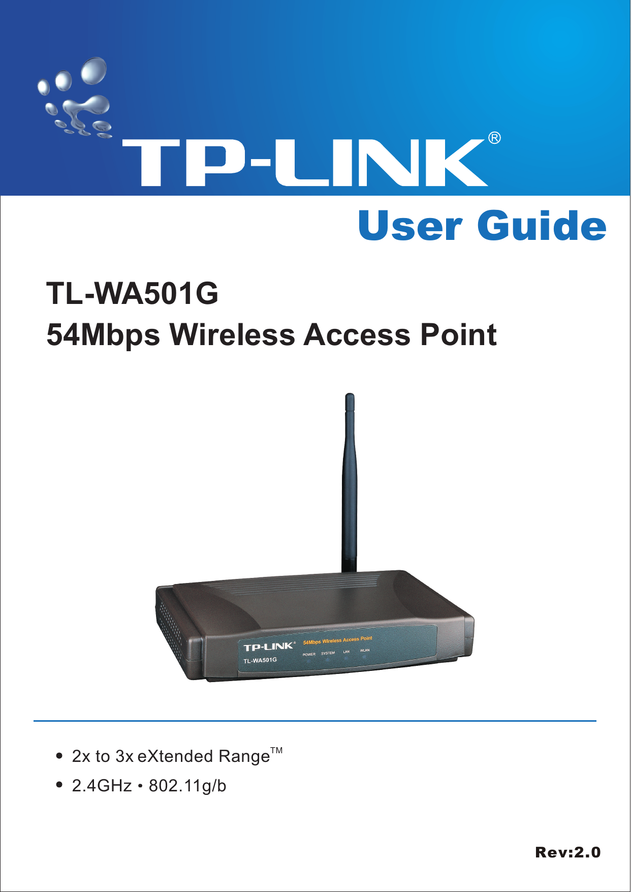
TP-Link Technologies Co., Ltd. 54M Wireless Access Point Users Manual

Revised Manual

User GuideTL-WA501G54Mbps Wireless Access PointTM2x to 3x eXtended Range2.4GHz 802.11g/bRev:2.0
  COPYRIGHT & TRADEMARKS  Specifications are subject to change without notice.   is a registered trademark of TP-LINK Technologies Co., Ltd. Other brands and product names are trademarks or registered trademarks of their respective holders.  No part of the specifications may be reproduced in any form or by any means or used to make any derivative such as translation, transformation, or adaptation without permission from TP-LINK Technologies Co., Ltd. Copyright © 2006 TP-LINK Technologies Co., Ltd. All rights reserved.
FCC STATEMENT This equipment has been tested and found to comply with the limits for a class B digital device, pursuant to part 15 of the FCC Rules. These limits are designed to provide reasonable protection against harmful interference in a residential installation. This equipment generates, uses and can radiate radio frequency energy and, if not installed and used in accordance with the instructions, may cause harmful interference to radio communications. However, there is no guarantee that interference will not occur in a particular installation. If this equipment does cause harmful interference to radio or television reception, which can be determined by turning the equipment off and on, the user is encouraged to try to correct the interference by one or more of the following measures: ¾ Reorient or relocate the receiving antenna. ¾ Increase the separation between the equipment and receiver. ¾ Connect the equipment into an outlet on a circuit different from that to which the receiver is connected. ¾ Consult the dealer or an experienced radio/TV technician for help. This device complies with Part 15 of the FCC Rules. Operation is subject to the following two conditions: (1) This device may not cause harmful interference. (2) This device must accept any interference received, including interference that may cause undesired operation. Changes or modifications to this unit not expressly approved by the party responsible for compliance could void the user's authority to operate the equipment.  FCC RF Radiation Exposure Statement:   This equipment complies with FCC RF radiation exposure limits set forth for an uncontrolled environment. This device and its antenna must not be co-located or operating in conjunction with any other antenna or transmitter.   “To comply with FCC RF exposure compliance requirements, the antenna used for this transmitter must be installed to provide a separation distance of at least 20 cm from all persons and must not be co-located or operating in conjunction with any other antenna or transmitter”.  CE Declaration of Conformity For the following equipment: TL-WA501G  Is herewith confirmed to comply with the requirements set out in the Council Directive on the Approximation of the Laws of the Member States relating to Electromagnetic Compatibility (89/336/EEC), Low-voltage Directive (73/23/EEC) and the Amendment Directive (93/68/EEC), the procedures given in European Council Directive 99/5/EC and 89/3360EEC.   The equipment was passed. The test was performed according to the following European standards: ¾ EN 300 328 V.1.4.1 (2003) ¾ EN 301 489-1 V.1.4.1 (2002) / EN 301 489-17 V.1.2.1 (2002)
¾ EN 60950-1: 2001 ¾ EN 55022: 1998 + A1: 2000 + A2: 2003 ¾ EN61000-3-2:2001 ¾ EN61000-3-3:2001 ¾ EN 55024: 1998 +A1: 2001 + A2: 2003 European standards dictate maximum radiated transmit power of 100mW EIRP and frequency range 2.400-2.4835GHz; In France, the equipment must be restricted to the 2.4465-2.4835GHz frequency range and must be restricted to indoor use.
 Package contents.............................................................................................................. 1 Chapter 1: About this Guide .............................................................................................. 2 1.1 Purposes.............................................................................................................. 2 1.2 Conventions ......................................................................................................... 2 1.3 Overview of this User Guide ................................................................................ 2 Chapter 2: Introduction...................................................................................................... 3 2.1 Overview of the AP .............................................................................................. 3 2.2 Features............................................................................................................... 3 2.3 Panel Layout ........................................................................................................ 4 2.3.1 The Front Panel ......................................................................................... 4 2.3.2 The Rear Panel.......................................................................................... 4 Chapter 3: Connecting the AP........................................................................................... 6 3.1 System Requirements.......................................................................................... 6 3.2 Installation Environment Requirements................................................................ 6 3.3 Connecting the AP ............................................................................................... 6 Chapter 4: TCP/IP Configuration....................................................................................... 8 Chapter 5: Configuring the AP ........................................................................................ 10 5.1 login ................................................................................................................... 10 5.2 Status................................................................................................................. 10 5.3 Network...............................................................................................................11 5.4 Wireless ............................................................................................................. 12 5.4.1 Basic Settings .......................................................................................... 12 5.4.2 Site Survey .............................................................................................. 18 5.4.3 Security Settings ...................................................................................... 18 5.4.4 MAC Filtering ........................................................................................... 20 5.4.5 Wireless Statistics.................................................................................... 23 5.5 DHCP................................................................................................................. 24 5.5.1 DHCP Settings......................................................................................... 24 5.5.2 DHCP Clients List .................................................................................... 25 5.5.3 Address Reservation................................................................................ 25 5.6 Wireless Advanced Settings............................................................................... 26 5.7 System Tools...................................................................................................... 27 5.7.1 Firmware.................................................................................................. 27 5.7.2 Factory Defaults....................................................................................... 28 5.7.3 Reboot ..................................................................................................... 28 5.7.4 Password ................................................................................................. 29 5.7.5 Log........................................................................................................... 29 Appendix A: FAQ............................................................................................................. 31 Appendix B: Configuring the PCs.................................................................................... 32 Appendix C: Specifications.............................................................................................. 37 Appendix D: Glossary ..................................................................................................... 38 A ppendix E: Contact Information..................................................................................... 40
TL-WA501G   54M Wireless Access Point User Guide  Package contents The following contents should be found in your box: ¾ One TL-WA501G 54Mbps Wireless Access Point ¾ One AC power Adapter for TL-WA501G 54Mbps Wireless Access Point ¾ One Resource CD for TL-WA501G 54Mbps Wireless Access Point, including: • This Guide • Other Helpful Information  Note: If any of the listed contents are damaged or missing, please contact the retailer from whom you purchased the TL-WA501G 54Mbps Wireless Access Point for assistance.  - 1 -
TL-WA501G   54M Wireless Access Point User Guide  Chapter 1: About this Guide Thank you for choosing the TL-WA501G 54Mbps Wireless Access Point. This AP provides connectivity between Ethernet wired networks and radio-equipped wireless devices. It adopts 2x to 3x eXtended RangeTM WLAN transmission technology so that transmission distance is 2-3 times of traditional IEEE 802.11g/b solutions, up to 855.36m tested in China. Transmission range is extended to 4-9 times. It is an easy, web-based setup for installation and management. Even though you may not be familiar with the AP, this guide will make configuring the AP easy. Before installing the AP, please look through this guide to get to know all the AP’s functions. 1.1 Purposes This Guide tells you how to use the TL-WA501G 54Mbps Wireless Access Point.   1.2 Conventions The AP mentioned in this guide stands for TL-WA501G 54Mbps Wireless Access Point. 1.3 Overview of this User Guide Chapter 1: About this Guide Chapter 2: Introduction Chapter 3: Connecting the AP Chapter 4: TCP/IP Configuration Chapter 5: Configuring the AP Appendix A: FAQ Appendix B: Configuring the PCs Appendix C: Specifications Appendix D: Glossary Appendix E: Contact Information  - 2 -
TL-WA501G   54M Wireless Access Point User Guide  Chapter 2: Introduction 2.1 Overview of the AP The TL-WA501G 54Mbps Wireless Access Point is the basic building block of a wireless LAN infrastructure. It provides connectivity between Ethernet wired networks and radio-equipped wireless notebook systems, desktop systems, print servers, and other devices.   The TL-WA501G 54Mbps Wireless Access Point acts as a bridge between the wired LAN and wireless clients. Connecting multiple TL-WA501G Access Points via a wired Ethernet backbone can further lengthen the wireless network coverage. As a mobile computing device moves out of the range of one access point, it moves into the range of another. As a result, wireless clients can freely roam from one Access Point to another and still maintain seamless connection to the network. In the most attentive wireless security, the TL-WA501G 54Mbps Wireless Access Point provides multiple protection measures. It can be set to turn off wireless network name (SSID) broadcast so that only stations that have the SSID can be connected. The AP provides wireless LAN 64/128/152-bit WEP encryption security, and WPA/WPA2 and WPA-PSK/WPA2-PSK authentication, as well as TKIP/AES encryption security. It also supports VPN pass-through for sensitive data secure transmission. The TL-WA501G 54Mbps Wireless Access Point complies with the IEEE 802.11g/b standards so that the data transmission rate is up to 54Mbps. It adopts 2x to 3x eXtended RangeTM WLAN transmission technology so that transmission distance is 2-3 times of traditional IEEE 802.11g/b solutions, up to a distance of 855.36m tested in China. Transmission range is extended to 4-9 times. It is compatible with all IEEE 802.11g and IEEE 802.11b products. 2.2 Features ¾  Complies with IEEE802.11g, IEEE802.11b, IEEE802.3, IEEE802.3u standards ¾ Adopts 2x to 3x eXtended RangeTM WLAN transmission technologies ¾ Supports 54/48/36/24/18/12/9/6Mbps or 11/5.5/3/2/1Mbps wireless LAN data transfer rates ¾  Provides 64/128/152-bit WEP encryption security ¾  Provides WPA/WPA2 and WPA-PSK/WPA2-PSK authentication and TKIP/AES encryption security ¾  Built-in DHCP server supporting dynamic IP address distributing ¾  Supports MAC address filtering ¾  Supports multiple operating modes (Access Point, Client, Repeater, Point to Point, Point to Multi-point) ¾  Supports TCP/IP, DHCP, SNMP ¾ Supports Traffic statistics ¾  Supports firmware upgrade ¾  Supports Remote and Web management  - 3 -
TL-WA501G   54M Wireless Access Point User Guide  2.3 Panel Layout 2.3.1 The Front Panel Viewed from left to right, as shown in figure 2-1, the front panel of the TL-WA501G consists of four LEDs, which is designed to indicate connections. Table 2-1 describes the LEDs on the front panel of the AP.                Figure 2-1: Front Panel sketch  Name Action  Description Not lit  No Power POWER  Lit up  Power on Lit up  The AP is initialising Flashing  The AP is working properly SYSTEM Not lit  The AP has a hardware error Not lit  There is no device linked to the corresponding port Lit up  There is a device linked to the corresponding port but no activity LAN Flashing  There is an active device linked to the corresponding portNot lit  The Wireless Radio function is disabled WLAN  Flashing  The Wireless Radio function is enabled             Table 2-1 The LEDs description 2.3.2 The Rear Panel The rear panel contains the following features: (Viewed from left to right in figure 2-2) ¾ Wireless antenna ¾  Factory Default Reset button ¾  There are two ways to reset the AP's factory defaults: 1) Use the Factory Defaults function on System Tools -> Factory Defaults page in the AP's Web-based Utility. 2)  Use the Factory Default Reset button: First, turn off the AP's power. Second, press and hold the default reset button then turn on the AP's power, until the system LED lights up (about 3 seconds). Last, release the reset button and wait for the AP to reboot. Note: Ensure the AP is powered on before it restarts completely. ¾  One LAN 10/100Mbps RJ45 port for connecting the AP to hub or switch ¾  AC power socket: only use the power adapter supplied with the TL-WA501G 54Mbps Wireless Access Point, use of a different adapter may result in product damage.  - 4 -
TL-WA501G   54M Wireless Access Point User Guide   Figure 2-2: Rear Panel sketch    - 5 -
TL-WA501G   54M Wireless Access Point User Guide  Chapter 3: Connecting the AP 3.1 System Requirements ¾ Broadband Internet Access Service (DSL/Cable/Ethernet) ¾ One DSL/Cable Modem that has an RJ45 connector ¾ A Ethernet broadband router ¾ TCP/IP protocol must be installed on each PC ¾ Web browser, such as Microsoft Internet Explorer 5.0 or later, Netscape Navigator 6.0 or later ¾ 802.11g or 802.11b-compliant devices, such as the TL-WN510G Wireless Adapter 3.2 Installation Environment Requirements ¾ Not in direct sunlight or near a heater or heating vent ¾ Not cluttered or crowded. There should be at least 2 inches (5 cm) of clear space on all sides of the AP ¾ Well ventilated (especially if it is in a closet) ¾ Operating temperature: 0℃~40℃ (32℉~104℉) ¾ Operating Humidity: 10%~90%RH, Non-condensing 3.3 Connecting the AP   Figure 3.1 is an example of an infrastructure network incorporating the TL-WA501G. An Infrastructure network contains an access point or a wireless router. For a typical connection of the AP, please do the following: 1.  You will need broadband Internet access (a Cable or DSL-subscriber line into your home or office). Consult with your Cable or DSL provider for proper installation of the modem. 2.  Connect the Cable or DSL modem to a Router. Quickly install the router. 3.  Locate an optimum location for the AP. The best place is usually near the center of the area in which your PC(s) will wirelessly connect. The place must accord with the Installation Environment Requirements. 4.  Adjust the direction of the antenna. Normally, upright is a good direction. 5.  Connect the Ethernet Broadband Router to the TL-WA501G AP. Power on the AP. 6.  If you are connecting a desktop PC or laptop to your network, install the TP-LINK Wireless Adapter on the PC.    - 6 -
TL-WA501G   54M Wireless Access Point User Guide   Figure 3-1    The Example of Infrastructure Network Incorporating the TL-WA501G    - 7 -
TL-WA501G   54M Wireless Access Point User Guide  Chapter 4: TCP/IP Configuration After connecting the TL-WA501G AP into your network, you should configure it. The default IP address of the TL-WA501G 54Mbps Wireless Access Point is 192.168.1.1, and the default Subnet Mask is 255.255.255.0. These values can be seen from the LAN. They can be changed as you desire, as an example we use the default values for description in this guide. Connect the local PCs to the LAN ports on the AP. There are then two means to configure the IP address for your PCs. ¾ Configure the IP address manually 1)  Set up the TCP/IP Protocol for your PC(s). If you need instructions as to how to do this, please refer to Appendix B: "Configuring the PCs." 2)  Configure the network parameters. The IP address is 192.168.1.xxx ("xxx" is from 2 to 254), Subnet Mask is 255.255.255.0, and Gateway is 192.168.1.1 (The AP's default IP address) ¾ Obtain an IP address automatically 1)  Set up the TCP/IP Protocol in "Obtain an IP address automatically" mode on your PC(s). If you need instructions as to how to do this, please refer to Appendix B: "Configuring the PCs." 2)  Power off the AP and PC(s). Then turn on the AP, and restart the PC(s). The built-in DHCP server will assign IP addresses for the PC(s). Now, you can run the Ping command in the command prompt to verify the network connection between your PC(s) and the AP. The following example is in Windows 2000 OS. Open a command prompt, and type ping 192.168.1.1, then press Enter.  Figure 4-1: Successful result of Ping command If the result displayed is similar to that shown in figure 4-1, the connection between your PC and the AP has been established.    - 8 -
TL-WA501G   54M Wireless Access Point User Guide   Figure 4-2: Failed result of Ping command If the result displayed is similar to that shown in figure 4-2, it means that your PC has not connected to the AP. Please check it following these steps: 1.  Is the connection between your PC and the AP correct? Note: The LED of LAN port on the AP and LED on your PC's adapter should be lit. 2. Is the TCP/IP configuration for your PC correct? Note: If the AP's IP address is 192.168.1.1, your PC's IP address must be within the range of 192.168.1.2 ~ 192.168.1.254, the gateway must be 192.168.1.1  - 9 -
TL-WA501G   54M Wireless Access Point User Guide  Chapter 5: Configuring the AP This chapter describes each web page's key functions. 5.1 login   With a Web-based (Internet Explorer or Netscape® Navigator) utility, the TL-WA501G 54Mbps Wireless Access Point is easy to configure and manage. The Web-based utility can be used on any Windows, Macintosh or UNIX OS with a web browser. Connect to the AP by typing http://192.168.1.1 in the address field of web browser.  Figure 5-1: Login to the AP After a moment, a login window will appear similar to that shown in Figure 5-2. Enter admin for the User Name and Password, both in lower case letters. Then click the OK button or press the Enter key.   Figure 5-2: Login Windows Note: If the above screen does not prompt, it means that your web-browser has been set to a proxy. Go to Tools menu>Internet Options>Connections>LAN Settings, in the screen that appears, cancel the Using Proxy checkbox, and click OK to finish it. After your successful login, you can configure and manage the AP. There are six main menus on the left of the web-based utility. Submenus will be available after you click one of the main menus. The six main menus are: Status, Network, Wireless, DHCP, Wireless Advanced Settings and System Tools. On the right of the web-based utility, there are the detailed explanations and instructions for the corresponding page. To apply any settings you have altered on the page, please click the Save button.   There are the detailed explanations for each web page's key functions below.   5.2 Status The Status page displays the AP's current status and configuration. All information is  - 10 -
TL-WA501G   54M Wireless Access Point User Guide  read-only. 1. Network This field displays the current settings or information for the Network, including the MAC address, IP address and Subnet Mask. 2. Wireless This field displays basic information or status for wireless function, including Operating Mode, SSID, Channel, Mode, MAC Address and IP Address. 3. Traffic Statistics This field displays the AP's traffic statistics.   4.  System Up Time The time of the AP running from it's powered on or reset.  Figure 5-3: AP Status 5.3 Network You can configure the IP parameters of Network on this page.    Figure 5-4: Network  - 11 -
TL-WA501G   54M Wireless Access Point User Guide  ¾ MAC Address - the physical address of the AP, as seen from the LAN. The value can't be changed. ¾ IP Address - Enter the IP address of your AP in dotted-decimal notation (factory default: 192.168.1.1). ¾ Subnet Mask - An address code that determines the size of the network. Normally use 255.255.255.0 as the subnet mask.   Note:  a.  If you change the IP Address, you must use the new IP Address to login the AP.   b.  If the new LAN IP Address you set is not in the same subnet, the IP Address pool in the DHCP sever will not take effect, until they are re-configured. 5.4 Wireless  Figure 5-5: Wireless menu There are four submenus under the Wireless menu (shown in figure 5-5): Basic Settings, Security Settings, MAC Filtering and Wireless Statistics. Click any of them, and you will be able to configure the corresponding function. The detailed explanations for each submenu are provided below. 5.4.1 Basic Settings The basic settings for the wireless network are set on this page, figure 5-6a:  - 12 -
TL-WA501G   54M Wireless Access Point User Guide   Figure 5-6a: Wireless Settings ¾ Channel - This field determines which operating frequency will be used. It is not necessary to change the wireless channel unless you notice interference problems with another nearby access point. ¾ Mode - Select the desired wireless mode. The options are:   • 54Mbps (802.11g) - Both 802.11g and 802.11b wireless stations can connect to the AP. • 11Mbps (802.11b)  - Only 802.11b wireless stations can connect to the AP. Note: The default is "54Mbps (802.11g)", which allows both 802.11g and 802.11b wireless stations to connect to the AP.  - 13 -
TL-WA501G   54M Wireless Access Point User Guide  ¾ Region - Select your region from the pull-down list. This field specifies the region where the wireless function of the AP can be used. If your country or region is not listed, please contact your local government agency for assistance. The default region is United States. When you select your local region from the pull-down list, the dialog shown in Figure 5-7 appears. Click OK.  Figure 5-7: Note Dialog   Notes: Limited by local law regulations, version for North America does not have region selection option. The wireless basic settings for this version are shown below.                  Figure 5-6b: Wireless Settings for No Region Option  - 14 -
TL-WA501G   54M Wireless Access Point User Guide  ¾ Disable Wireless - The wireless of this AP can be enabled or disabled to allow wireless stations access. If disabled, wireless stations will not be able to access the AP. AP provides five operational modes: Access Point, Client, Repeater, Bridge (point to point), Bridge (point to Multi-point). ¾ Access Point - Access Point mode allows wireless stations including AP clients to access.  • SSID - Enter a value of up to 32 characters. The same name (SSID) must be assigned to all wireless devices in your network. The default SSID is TP-LINK, but it is recommended strongly that you change your networks name (SSID) to a different value. This value is case-sensitive. For example, TP-LINK is NOT the same as tp-link. • Enable SSID Broadcast - If you select the Enable SSID Broadcast checkbox, the Wireless Access Point SSID will broadcast its name (SSID) on the air. ¾ Client - This mode allows one or more remote LANs connect with a central LAN, and thus creating an extended virtual LAN. In this way, any station of the Remote LAN can successfully communicate with any station of the central LAN, as if all of them belong to the same physical LAN. Wireless Stations can’t associate with AP Clients. • SSID - Enter the SSID of AP that you want to access. If you select the radio before SSID, the AP client will connect to AP according SSID.   • MAC of AP - Enter the MAC address of AP that you want to access. If you select the radio before MAC of AP, the AP client will connect to AP according MAC address.  ¾ Repeater - A wireless repeater is an AP with its own BSS that relays data to a root AP, to which it is associated. The wireless repeater relays signal between its stations and the root AP for greater wireless range. Please input the MAC address of root AP in the field of MAC of AP.   Here is an example of how to configure wireless repeater. Please do the following: 1.  Configure the Operating Mode of the TL-WA501G Access Points.   • Configure AP1 on LAN Segment 1 in Access Point mode. • Configure AP2 in Repeater mode with the MAC address of its root AP (AP1). • Configure AP3 in Repeater mode with the MAC Address of its root AP (AP2).    - 15 -
TL-WA501G   54M Wireless Access Point User Guide   Figure 5-8: wireless repeating 2. Verify the wireless security parameters for all access points, if any.   3.  Verify connectivity across the LANs. A computer on any LAN segment should be able to connect to the Internet or share files and printers with any other PCs or servers connected to any of the three WLAN segments. Note: You can extend this repeating by adding up to 2 additional TL-WA501Gs configured in repeater mode. However, since Repeater configurations communicate in half-duplex mode, the bandwidth decreases as you add Repeaters to the network. Also, you can extend the range of the wireless network with wireless antenna accessories.    ¾ Bridge (Point to Point) - This mode bridges the AP and another AP also in bridge mode to connect two wired LANs. Please input the MAC address of the other AP in the field of MAC of AP.   Here is an example of how to configure Point-to-Point Bridge. Please do the following:  Figure 5-9: Point to Point Bridge 1.  Configure the TL-WA501G (AP1) on LAN Segment 1 in Point-to-Point Bridge mode.   2.  Configure the TL-WA501G (AP2) on LAN Segment 2 in Point-to-Point Bridge mode. AP1 must have AP2’s MAC address in its MAC Address field and AP2 must have AP1’s MAC address in its MAC Address field.   3.  Configure and verify the following parameters for both access points:    - 16 -
TL-WA501G   54M Wireless Access Point User Guide  • Both use the same Channel, and security settings if security is in use. • Verify connectivity across the LAN 1 and LAN 2. A computer on either LAN segment should be able to connect to the Internet or share files and printers of any other PCs or servers connected to LAN Segment 1 or LAN Segment 2. ¾ Bridge (Point to Multi-Point) - This mode bridges the AP and up to 4 APs also in bridge mode to connect two or more wired LANs. Please input the MAC address of other APs in the field of MAC of AP1 to MAC of AP4.   Here is an example of how to configure multi-point bridging. Please do the following:  Figure 5-10: Point to Multi-point Bridge 1.  Configure the Operating Mode of the TL-WA501G Access Points.   • Because it is in the central location, configure TL-WA501G (AP1) on LAN Segment 1 in Point-to-Multi-Point Bridge mode. The MAC addresses of AP2 and AP3 are required in AP1. • Configure TL-WA501G (AP2) on LAN Segment 2 in Point-to-Point Bridge mode with the MAC Address of AP1. • Configure the TL-WA501G (AP3) on LAN 3 in Point-to-Point Bridge mode with the MAC Address of AP1.   2.  Verify the following parameters for all access points. • All TL-WA501G Access Points use the same Channel, and security settings if any.  • All Point-to-Point APs must have AP1’s MAC address in its AP MAC address field, and AP1 must have all All Point-to-Point APs’ MAC addresses. 3. Verify connectivity across the LANs.   • A computer on any LAN segment should be able to connect to the Internet or  - 17 -
TL-WA501G   54M Wireless Access Point User Guide  share files and printers with any other PCs or servers connected to any of the three LAN segments.   • Wireless stations will not be able to connect to the TL-WA501G Access Points in the illustration above. If you require wireless stations to access any lan segment, you can add TL-WA501G Access Points configured in Wireless Access Point mode to any LAN segment.   Note:  You can extend this multi-point bridging by adding additional TL-WA501Gs configured in Point-to-Point mode for each additional LAN segment. Furthermore, you can extend the range of the wireless network with wireless antenna accessories.   5.4.2 Site Survey After selecting a mode and pressing button Survey, you can view all of APs around you.  Figure 5-11:  Site Survey ¾ SSID - The SSID of the AP. ¾ BSSID - The BSSID of the AP, usually also the MAC address of the AP. ¾ Signal - The signal received from the AP. ¾ Channel - The channel the AP works in. ¾ Security - The AP communicates in privacy. ¾ Choose - Choose one AP from list to connect to.  Press one of Connect in list to select an AP to connect to. Then the basic settings will show again. You can save settings and reboot to take effective.  Note: If wireless is disabled, surveying can’t work. And if Access Point mode is selected, there is no reason and no choice to connect to another AP. 5.4.3 Security Settings You can select one of the following security options:    - 18 -
TL-WA501G   54M Wireless Access Point User Guide   Figure 5-12:  Wireless Securities ¾ Disable Security - The wireless security function can be enabled or disabled. If disabled, the wireless stations will be able to connect the AP without encryption. It is recommended strongly that you choose one of following options to enable security. ¾ WEP - Select 802.11 WEP security. • Type - You can select one of following types: 1)  Automatic - Select Shared Key or Open System authentication type automatically based on the wireless station's capability and request.   2)  Shared Key - Select 802.11 Shared Key authentication.   3)  Open System - Select 802.11 Open System authentication.  • WEP Key Format - You can select ASCII or Hexadecimal format. ASCII Format stands for any combination of keyboard characters in the specified length. Hexadecimal format stands for any combination of hexadecimal digits (0-9, a-f, A-F) in the specified length. • WEP Key settings - Select which of the four keys will be used and enter the matching WEP key information for your network in the selected key radio button. These values must be identical on all wireless stations in your network.   • Key Type - You can select the WEP key length (64-bit, or 128-bit, or 152-bit.) for encryption. "Disabled" means this WEP key entry is invalid. 1)  For 64-bit encryption - You can enter 10 hexadecimal digits (any combination of 0-9, a-f, A-F, zero key is not permitted) or 5 ASCII characters.    - 19 -
TL-WA501G   54M Wireless Access Point User Guide  2)  For 128-bit encryption - You can enter 26 hexadecimal digits (any combination of 0-9, a-f, A-F, zero key is not permitted) or 13 ASCII characters.  3)  For 152-bit encryption - You can enter 32 hexadecimal digits (any combination of 0-9, a-f, A-F, zero key is not permitted) or 16 ASCII characters.  Note: If you do not set the key, the wireless security function is still disabled even if you have selected Shared Key as Authentication Type.   ¾ WPA/WPA2 - Select WPA/WPA2 based on Radius Server. • Version - You can select one of following versions, 1)  Automatic - Select WPA or WPA2 automatically based on the wireless station's capability and request.   2)  WPA - Wi-Fi Protected Access.   3)  WPA2 - WPA version 2.   • Encryption - You can select either Automatic, or TKIP or AES. • Radius Server IP - Enter the IP address of the Radius Server. • Radius Port - Enter the port that radius service used. • Radius Password - Enter the password for the Radius Server. ¾ WPA-PSK/ WPA2-PSK - Select WPA based on pre-shared passphrase. • Version - You can select one of following versions, 1) Automatic - Select WPA-PSK or WPA2-PSK automatically based on the wireless station's capability and request.   2) WPA-PSK - Pre-shared key of WPA.  3) WPA2-PSK - Pre-shared key of WPA2.   • PSK Passphrase - You can enter a passphrase between 8 and 63 characters long. • Group Key Update Period - Specifiy the group key update interval in seconds. The value can be either 0 or at least 30. Enter 0 to disable the update. Be sure to click the Save button to save your settings on this page. Note: The AP will reboot automatically after you click the Save button if you have select the Reboot checkbox.   5.4.4 MAC Filtering   The Wireless MAC Filtering for wireless networks are set on this page, figure 5-13:  - 20 -
TL-WA501G   54M Wireless Access Point User Guide   Figure 5-13: Wireless MAC address Filtering The Wireless MAC Address Filtering feature allows you to control wireless stations accessing the AP, which depend on the station's MAC addresses.   ¾ MAC Address - The wireless station's MAC address that you want to access.   ¾ Description - A simple description of the wireless station.   ¾ Privilege - Allow means allowing the station to access the AP. Deny means denying the station to access the AP. 64-bit, or 128-bit, or 152-bit means assigning a unique WEP key to access the AP.   ¾ WEP Key - Specify a unique WEP key (in Hexadecimal format) to access the AP.   ¾ Status - The status of this entry, either Enabled or Disabled. To disable the Wireless MAC Address Filters feature, keep the default setting, Disable. To set up an entry, click Enable, and follow these instructions:   First, you must decide whether the unspecified wireless stations can or cannot access the AP. If you desire that the unspecified wireless stations can access the AP, please select the radio button Allow the stations not specified by any enabled entries in the list to access, otherwise, select the radio button Deny the stations not specified by any enabled entries in the list to access. To Add a Wireless MAC Address filtering entry, click the Add New… button. The " Add or Modify Wireless MAC Address Filtering entry" page will appear, shown in figure 5-14:  Figure 5-14: Add or Modify Wireless MAC Address Filtering entry To add or modify a MAC Address Filtering entry, follow these instructions: 1.  Enter the appropriate MAC Address into the MAC Address field. The format of the MAC Address is XX-XX-XX-XX-XX-XX (X is any hexadecimal digit). For example: 00-0A-EB-B0-00-0B.   - 21 -
TL-WA501G   54M Wireless Access Point User Guide  2.  Enter a simple description of the wireless station in the Description field. For example: Wireless station A. 3.  Privilege - Selects the privileges for this entry, one of Allow / Deny / 64-bit / 128-bit / 152-bit.  4.  WEP Key - If you select 64-bit, 128-bit or 152-bit in the Privilege field, enter any combination of hexadecimal digits (0-9, a-f, A-F) in the specified length. For example: 2F34D20BE2.   5.  Status - Select Enabled or Disabled for this entry on the Status pull-down list. 6. Click the Save button to save this entry. To add additional entries, repeat steps 1-6. Note: When 64-bit, or 128-bit, or 152-bit is selected, WEP Key will be enabled.   To modify or delete an existing entry: 1. Click the Edit or Delete button in the Modify column in the MAC Address Filtering Table. 2.  Enter the value as desired in the Add or Modify Wireless MAC Address Filtering entry page, and click the Save button. You can click the Enable All button to make all the entries effective, click the Disable All button to make all the entries ineffective, click the Delete All button to delete all the entries. Click the Next button to go to the next page and click the Previous button to return to the previous page. For example: If you desire that the wireless station A with MAC address 00-0A-EB-00- 07-BE be able to access the AP, the wireless station B with MAC address 00-0A-EB- 00-07-5F not be able to access the AP, and the wireless station C with MAC address 00-0A-EB-00-07-8A be able to access the AP when its WEP key is 2F34D20BE2E 54B326C5476586A, while all other wireless stations cannot access the AP, you should configure the Wireless MAC Address Filtering list following these steps: 1. Click the Enable button to enable this function. 2.  Select the radio button: Deny the stations not specified by any enabled entries in the list to access for Filtering Rules. 3.  Delete all or disable all entries if there exist any entries already. 4. Click the Add New... button and enter the MAC address 00-0A-EB-00-07-BE in the MAC Address field, enter wireless station A in the Description field, select Allow in the Privilege pull-down list and select Enabled in the Status pull-down list. Click the Save and the Return button. 5. Click the Add New... button and enter the MAC address 00-0A-EB-00-07-5F in the MAC Address field, enter wireless station B in the Description field, select Deny in the Privilege pull-down list and select Enabled in the Status pull-down list. Click the Save and the Return button. 6. Click the Add New... button and enter the MAC address 00-0A-EB-00-07-8A in the MAC Address field, enter wireless station C in the Description field, select 128-bit in the Privilege pull-down list, enter 2F34D20BE2E54B326C5476586A in the WEP  - 22 -
TL-WA501G   54M Wireless Access Point User Guide  Key field and select Enabled in the Status pull-down list. Click the Save and the Return button. The filtering rules that configured should be similar to the following list:  Figure 5-15: The filtering list Note:  a)  If you select the radio button Allow the stations not specified by any enabled entries in the list to access for Filtering Rules, the wireless station B will still not be able to access the AP, however, other wireless stations that are not in the list will be able to access the AP. b)  If you enable the function and select the Deny the stations not specified by any enabled entries in the list to access for Filtering Rules, and there are not any enable entries in the list, thus, no wireless stations can access the AP. 5.4.5 Wireless Statistics This page shows MAC Address, Current Status, Received Packets and Sent Packets for each connected wireless station.  Figure 5-16: The AP attached wireless stations ¾ MAC Address - The connected wireless station's MAC address ¾ Current Status - The connected wireless station's running status, one of STA-AUTH / STA-ASSOC / STA-JOINED / WPA / WPA-PSK / WPA2 / WPA2-PSK / AP-UP / AP-DOWN / Disconnected ¾ Received Packets - packets received by the station ¾ Sent Packets - packets sent by the station You cannot change any of the values on this page. To update this page and to show the current connected wireless stations, click on the Refresh button.   If the numbers of connected wireless stations go beyond one page, click the Next button to go to the next page and click the Previous button to return the previous page. Note: This page will be refreshed automatically every 5 seconds.  - 23 -
TL-WA501G   54M Wireless Access Point User Guide  5.5 DHCP  Figure 5-17: the DHCP menu There are three submenus under the DHCP menu (shown in figure 5-17): DHCP Settings, DHCP Clients List and Address Reservation. Click any of them, and you will be able to configure the corresponding function. The detailed explanations for each submenu are provided below. 5.5.1 DHCP Settings The System can be set up as a DHCP (Dynamic Host Configuration Protocol) server, which provides the TCP/IP configuration for all the PCs that are connected to the system on the LAN. The DHCP Server can be configured on the page (shown in figure 5-18):  Figure 5-18: DHCP Settings ¾ DHCP Server - Enable or Disable the DHCP server. If you disable the Server, you must have another DHCP server within your network or else you must manually configure the computer. ¾ Start IP Address - This field specifies the first of the addresses in the IP address pool. 192.168.1.100 is the default start address. ¾ End IP Address - This field specifies the last of the addresses in the IP address pool. 192.168.1.199 is the default end address. ¾ Address Lease Time - The Address Lease Time is the amount of time a network user will be allowed connection to the system with their current dynamic IP Address. Enter the amount of time, in minutes, the user will be "leased" this dynamic IP Address. The range of the time is 1 ~ 2880 minutes. The default value is 120 minutes. ¾ Default Gateway - (Optional.) Suggest to input the IP address of the LAN port of the AP, default value is 192.168.1.1 ¾ Default Domain - (Optional.) Input the domain name of your network.  - 24 -
TL-WA501G   54M Wireless Access Point User Guide  ¾ Primary DNS - (Optional.) Input the DNS IP address provided by your ISP. Or consult your ISP. ¾ Secondary DNS - (Optional.) Input the IP address of another DNS server if your ISP provides two DNS servers. Note: To use the DHCP server function of the AP, you must configure all computers on the LAN as "Obtain an IP Address automatically" mode. This function will take effect until the AP reboots. 5.5.2 DHCP Clients List This page shows Client Name, MAC Address, Assigned IP and Lease Time for each DHCP Client attached to the AP (figure 5-19):  Figure 5-19: DHCP Clients List ¾ Index - The index of the DHCP Client   ¾ Client Name - The name of the DHCP client   ¾ MAC Address - The MAC address of the DHCP client   ¾ Assigned IP - The IP address that the AP has allocated to the DHCP client. ¾ Lease Time - The time of the DHCP client leased. Before the time is up, DHCP client will request to renew the lease automatically. You cannot change any of the values on this page. To update this page and to show the current attached devices, click on the Refresh button. 5.5.3 Address Reservation When you specify a reserved IP address for a PC on the LAN, that PC will always receive the same IP address each time when it accesses the DHCP server. Reserved IP addresses should be assigned to servers that require permanent IP settings. This page is used for address reservation (shown in figure 5-20).  - 25 -
TL-WA501G   54M Wireless Access Point User Guide   Figure 5-20:  Address Reservation ¾ MAC Address - The MAC address of the PC of which you want to reserve IP address. ¾ Assigned IP Address - The IP address of the AP reserved. To Reserve IP addresses:  1.  Enter the MAC address (The format for the MAC Address is XX-XX-XX-XX-XX-XX.) and IP address in dotted-decimal notation of the computer you wish to add.   2. Click the Save button when finished.   To modify A Reserved IP address:  1.  Select the reserved address entry as you desire, and modify it. If you wish to delete the entry, make all of the entry fields blank. 2. Click the Save button.   To delete all Reserved IP addresses: 1. Click the Clear All button. 2. Click the Save button Click the Next button to go to the next page and Click the Previous button to return the previous page. Note: The function won't take effect until the AP reboots. 5.6 Wireless Advanced Settings You can configure wireless advanced settings on this page.  - 26 -
TL-WA501G   54M Wireless Access Point User Guide   Figure5-21:  AP Wireless Advanced Settings ¾ Disable short preamble - Disable short preamble and use long preamble only. 802.11b mode supports only long preamble and this parameter will be ignored. ¾ RTS threshold - RTS/CTS Threshold, the packet size that is used to determine if RTS/CTS should be sent. ¾ Fragmentation threshold - The maximum packet size used for fragmentation. ¾ Beacon Interval - The interval time between two successive beacons.   5.7 System Tools  Figure 5-22: the System Tools menu There are five submenus under the System Tools menu (shown in figure 5-22): Firmware, Factory Defaults, Reboot, Password, and Log. Click any of them, and you will be able to configure the corresponding function. The detailed explanations for each submenu are provided below. 5.7.1 Firmware The page (shown in figure 5-23) allows you to upgrade the latest version of firmware for the AP.  Figure 5-23: Firmware Upgrade New firmware versions are posted at www.tp-link.com and can be downloaded for free. If the AP is not experiencing difficulties, there is no need to download a more recent firmware version, unless that version has a new feature that you want to use.  - 27 -
TL-WA501G   54M Wireless Access Point User Guide  Note: When you upgrade the AP's firmware, you may lose its configuration settings, so make sure you write down the AP settings before you upgrade its firmware. To upgrade the AP's firmware, follow these instructions: 1.  Download a more recent firmware upgrade file from the TP-LINK website (www.tp-link.com).  2.  Run a TFTP Server on a PC on your LAN, and take the file in the TFTP server’s path. 3.  Type the downloaded file name into the File Name box. 4.  Type the IP Address of the PC that runs the TFTP server in the TFTP Server’s IP Address field. 5. Click the Upgrade button.   ¾ Firmware Version - displays the current firmware version. ¾ Hardware Version - displays the current hardware version. The hardware version of the upgrade file must accord with the current hardware version. Note:  1.  Do not turn off the AP or press the Reset button while the firmware is being upgraded. 2.  The AP will reboot after the Upgrading has been finished. 5.7.2 Factory Defaults This page (shown in figure 5-24) allows you to restore the factory default settings for the AP.  Figure 5-24: Restore Factory Default Click the Restore button to reset all configuration settings to their default values.   • The default User Name: admin • The default Password: admin • The default IP Address: 192.168.1.1 • The default Subnet Mask: 255.255.255.0 Note: Any settings you have saved will be lost when the default settings are restored. 5.7.3 Reboot This page (shown in figure 5-25) allows you to reboot the AP.    - 28 -
TL-WA501G   54M Wireless Access Point User Guide  Figure 5-25: Reboot the AP Click the Reboot button to reboot the AP. Some settings of the AP will take effect only after rebooting, which include: •  Change LAN IP Address. (System will reboot automatically) •  MAC Clone (system will reboot automatically) •  DHCP service function. •  Static address assignment of DHCP server. •  Upgrade the firmware of the AP (system will reboot automatically). •  Restore the AP's settings to factory default (system will reboot automatically). 5.7.4 Password This page (shown in figure 5-26) allows you to change the factory default user name and password of the AP.    Figure 5-26: Password It is strongly recommended that you change the factory default user name and password of the AP. All users who try to access the AP's web-based utility or Quick Setup will be prompted for the AP's user name and password. Note: The new user name and password must not exceed 14 characters in length and must not include any spaces. Enter the new Password twice to confirm it. Click the Save button when finished. Click the Clear All button to clear all. 5.7.5 Log This page (shown in figure 5-27) allows you to query the Logs of the AP.    - 29 -
TL-WA501G   54M Wireless Access Point User Guide   Figure 5-27: System Log The AP can keep logs of all traffic. You can query the logs to find what happened to the AP. Click the Refresh button to refresh the logs. Click the Clear Log button to clear all the logs.  - 30 -
TL-WA501G   54M Wireless Access Point User Guide  Appendix A: FAQ 1.  No lights are lit on the access point. It takes a few seconds for the power indicator to light up. Wait a minute and check the power light status on the access point. If the access point has no power. 1)  Make sure the power cord is connected to the access point. 2)  Make sure the power adapter is connected to a functioning power outlet. If it is in a power strip, make sure the power strip is turned on. If it is plugged directly into the wall, verify that it is not a switched outlet. 3)  Make sure you are using the correct TP-LINK power adapter supplied with your access point. 2.  The LAN light is not lit. There is a hardware connection problem. Check these items: 1)  Make sure the cable connectors are securely plugged in at the access point and the network device (hub, switch, or router). 2)  Make sure the connected device is turned on. 3)  Be sure the correct cable is used. Use a standard Category 5 Ethernet patch cable. If the network device has Auto Uplink™ (MDI/MDIX) ports, you can use either a crossover cable or a normal patch cable. 3.  I cannot access the AP with a wireless capable computer. There is a configuration problem. Check these items: 1)  You may not have restarted the computer with the wireless adapter to have TCP/IP changes take effect. Restart the computer. 2)  The computer with the wireless adapter may not have the correct TCP/IP settings to communicate with the network. Restart the computer and check that TCP/IP is set up properly for that network. The usual setting for Windows the Network Properties is set to “Obtain an IP address automatically.” 3)    The access point’s default values may not work with your network. Check the access point default configuration against the configuration of other devices in your network.    - 31 -
TL-WA501G   54M Wireless Access Point User Guide  Appendix B: Configuring the PCs In this section, we’ll introduce how to install and configure the TCP/IP correctly in Windows 95/98. First make sure your Ethernet Adapter is working, refer to the adapter’s manual if needed.   1.  Install TCP/IP component 1)  On the Windows taskbar, click the Start button, point to Settings, and then click Control Panel. 2) Double-click the Network icon, click on the Configuration tab in the appearing Network window.  3)  Click on the Add button. Select Protocol, and then click Add.  Figure B-1: Add Network Protocol 4) Under Manufacturers on Select Network Protocol page, highlight Microsoft. Under Network Protocols, highlight TCP/IP. Click OK. TCP/IP protocol will take effect after reboot.  Figure B-2: Select Network Protocol 2.  Configure TCP/IP for your computer 1)  On the Windows taskbar, click the Start button, point to Settings, and then click Control Panel. 2) Double-click the Network icon, highlight the bound TCP/IP tab in the appearing Network window that appears. An example shown in the following figure:  - 32 -
TL-WA501G   54M Wireless Access Point User Guide   Figure B-3: Configuration tab 3) Click on Properties. The following TCP/IP Properties window will display and the IP Address tab is open on this window by default. 4)  Now you have two ways to configure the TCP/IP protocol below: • Assigned by DHCP Sever a. Select Obtain an IP address automatically, as shown in the figure below:  Figure B-4: IP Address tab b.  Do not type anything into the New gateway field on the Gateway tab.    - 33 -
TL-WA501G   54M Wireless Access Point User Guide   Figure B-5: Gateway tab c.  Choose Disable DNS on the DNS configuration tab, as shown in the following figure:  Figure B-6: DNS Configuration tab • Setting IP address manually a.  Select Specify an IP address on IP Address tab, as shown in the following figure. If the AP's LAN IP address is 192.168.1.1, type IP address is 192.168.1.x (x is from 2 to 254), and subnet mask is 255.255.255.0.  - 34 -
TL-WA501G   54M Wireless Access Point User Guide   Figure B-7: IP Address tab b.  Type the AP’s LAN IP address (the default IP is 192.168.1.1) into the New gateway field on the Gateway tab, and click on the Add button, as shown in the figure:    Figure B-8: Gateway tab c. On the DNS Configuration tab, click Enable DNS radio, and type your computer name in to the Host field and a Domain (such as szonline.com) into the Domain field. In the DNS Server Search Order field you can type the DNS server IP addresses, which has been provided by your ISP, and  - 35 -
TL-WA501G   54M Wireless Access Point User Guide  click Add button. Shown below:    Figure B-9: DNS Configuration tab Now, all the configurations are finished, it will take effect after reboot.  - 36 -
TL-WA501G   54M Wireless Access Point User Guide  Appendix C: Specifications General Standards  IEEE 802.3, 802.3u, 802.11b and 802.11g Protocols TCP/IP, DHCP Ports  One 10/100M Auto-Negotiation LAN RJ45 port supporting Auto MDI/MDIX Cabling Type  10BASE-T: UTP category 3, 4, 5 cable (maximum 100m)           EIA/TIA-568 100Ω STP (maximum 100m) 100BASE-TX: UTP category 5, 5e cable (maximum 100m)              EIA/TIA-568 100Ω STP (maximum 100m) Radio Data Rate  54/48/36/24/18/12/9/6Mbps or 11/5.5/3/2/1Mbps Power Supply  9V~ 0.8A LEDs  POWER, SYSTEM, LAN, WLAN Safety & Emissions  FCC, CE  Environmental and Physical Operating Temp.  0℃~40℃ (32℉~104℉) Operating Humidity  10% - 95% RH, Non-condensing Dimensions (W×D×H)   6.2×4.3×1.3 in. (158×110×32 mm) (without antenna)                        - 37 -
TL-WA501G   54M Wireless Access Point User Guide  Appendix D: Glossary ¾ 2x to 3x eXtended RangeTM WLAN Transmission Technology - The WLAN device with 2x to 3x eXtended RangeTM WLAN transmission technology make its sensitivity up to 105 dBm, which gives users the ability to have robust, longer-range wireless connections. With this range-enhancing technology, a 2x to 3x eXtended RangeTM based client and access point can maintain a connection at as much as three times the transmission distance of traditional 802.11b and 802.11g products, for a coverage area that is up to nine times greater. A traditional 802.11b and 802.11g product transmission distance is about 300m, A 2x to 3x eXtended RangeTM based client and access point can maintain a connection transmission distance may be up to 830m. ¾ 802.11b - The 802.11b standard specifies a wireless networking at 11 Mbps using direct-sequence spread-spectrum (DSSS) technology and operating in the unlicensed radio spectrum at 2.4GHz, and WEP encryption for security. 802.11b networks are also referred to as Wi-Fi networks. ¾ 802.11g - specification for wireless networking at 54 Mbps using direct-sequence spread-spectrum (DSSS) technology, using OFDM modulation and operating in the unlicensed radio spectrum at 2.4GHz, and backward compatibility with IEEE 802.11b devices, and WEP encryption for security. ¾ Access Point (AP) - A wireless LAN transceiver or "base station" that can connect a wired LAN to one or many wireless devices. Access points can also bridge to each other. ¾  DNS (Domain  Name  System) – An Internet Service that translates the names of websites into IP addresses. ¾ Domain Name - A descriptive name for an address or group of addresses on the Internet.  ¾ DoS (Denial  of  Service) - A hacker attack designed to prevent your computer or network from operating or communicating. ¾ DSL (Digital Subscriber Line) - A technology that allows data to be sent or received over existing traditional phone lines. ¾ ISP (Internet Service Provider) - A company that provides access to the Internet. ¾ MTU (Maximum Transmission Unit)  - The size in bytes of the largest packet that can be transmitted. ¾ SSID - A Service Set Identification is a thirty-two character (maximum) alphanumeric key identifying a wireless local area network. For the wireless devices in a network to communicate with each other, all devices must be configured with the same SSID. This is typically the configuration parameter for a wireless PC card. It corresponds to the ESSID in the wireless Access Point and to the wireless network name.    - 38 -
TL-WA501G   54M Wireless Access Point User Guide  ¾ WEP (Wired Equivalent Privacy) - A data privacy mechanism based on a 64-bit or 128-bit or 152-bit shared key algorithm, as described in the IEEE 802.11 standard.   ¾ Wi-Fi - A trade name for the 802.11b wireless networking standard, given by the Wireless Ethernet Compatibility Alliance (WECA, see http://www.wi-fi.net), an industry standards group promoting interoperability among 802.11b devices. ¾ WLAN  (Wireless  Local  Area  Network)  - A group of computers and associated devices communicate with each other wirelessly, which network serving users are limited in a local area. ¾ WPA (Wi-Fi Protected Access) - WPA is a security technology for wireless networks that improves on the authentication and encryption features of WEP (Wired Equivalent Privacy). In fact, WPA was developed by the networking industry in response to the shortcomings of WEP. One of the key technologies behind WPA is the Temporal Key Integrity Protocol (TKIP). TKIP addresses the encryption weaknesses of WEP. Another key component of WPA is built-in authentication that WEP does not offer. With this feature, WPA provides roughly comparable security to VPN tunneling with WEP, with the benefit of easier administration and use. This is similar to 802.1x support and requires a RADIUS server in order to implement. The Wi-Fi Alliance will call this, 'WPA-Enterprise. ' One variation of WPA is called WPA Pre Shared Key or WPA-PSK for short - this provides an authentication alternative to an expensive RADIUS server. WPA-PSK is a simplified but still powerful form of WPA most suitable for home Wi-Fi networking. To use WPA-PSK, a person sets a static key or "passphrase" as with WEP. But, using TKIP, WPA-PSK automatically changes the keys at a preset time interval, making it much more difficult for hackers to find and exploit them. The Wi-Fi Alliance will call this, 'WPA-Personal.'             - 39 -
TL-WA501G   54M Wireless Access Point User Guide  Appendix E: Contact Information For help with the installation or operation of the TP-LINK TL-WA501G 54Mbps Wireless Access Point, please contact us. E-mail: support@tp-link.com  Website: http://www.tp-link.com  Add: 3/F., Building R1-B, Hi-tech Industrial Park, Shennan Rd., Shenzhen, P. R. China   - 40 -

Navigation menu