TP Link Technologies WBS210 2.4GHz 300Mbps Outdoor Wireless Base Station User Manual WBS210 1 2016 06 29
TP-Link Technologies Co., Ltd. 2.4GHz 300Mbps Outdoor Wireless Base Station WBS210 1 2016 06 29
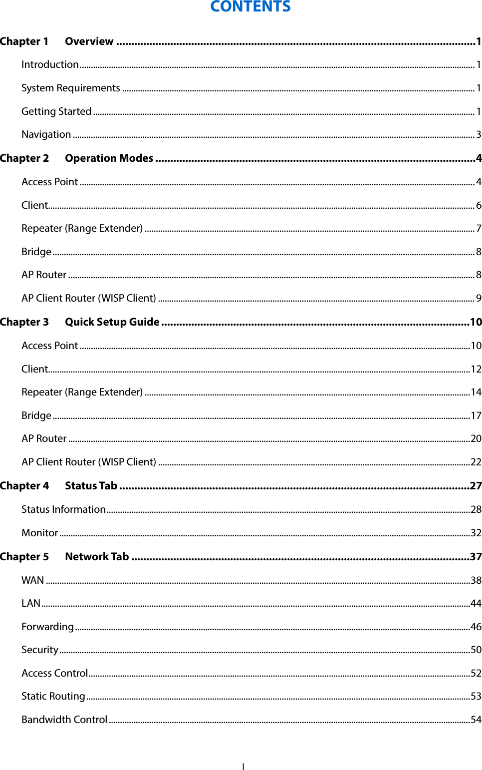
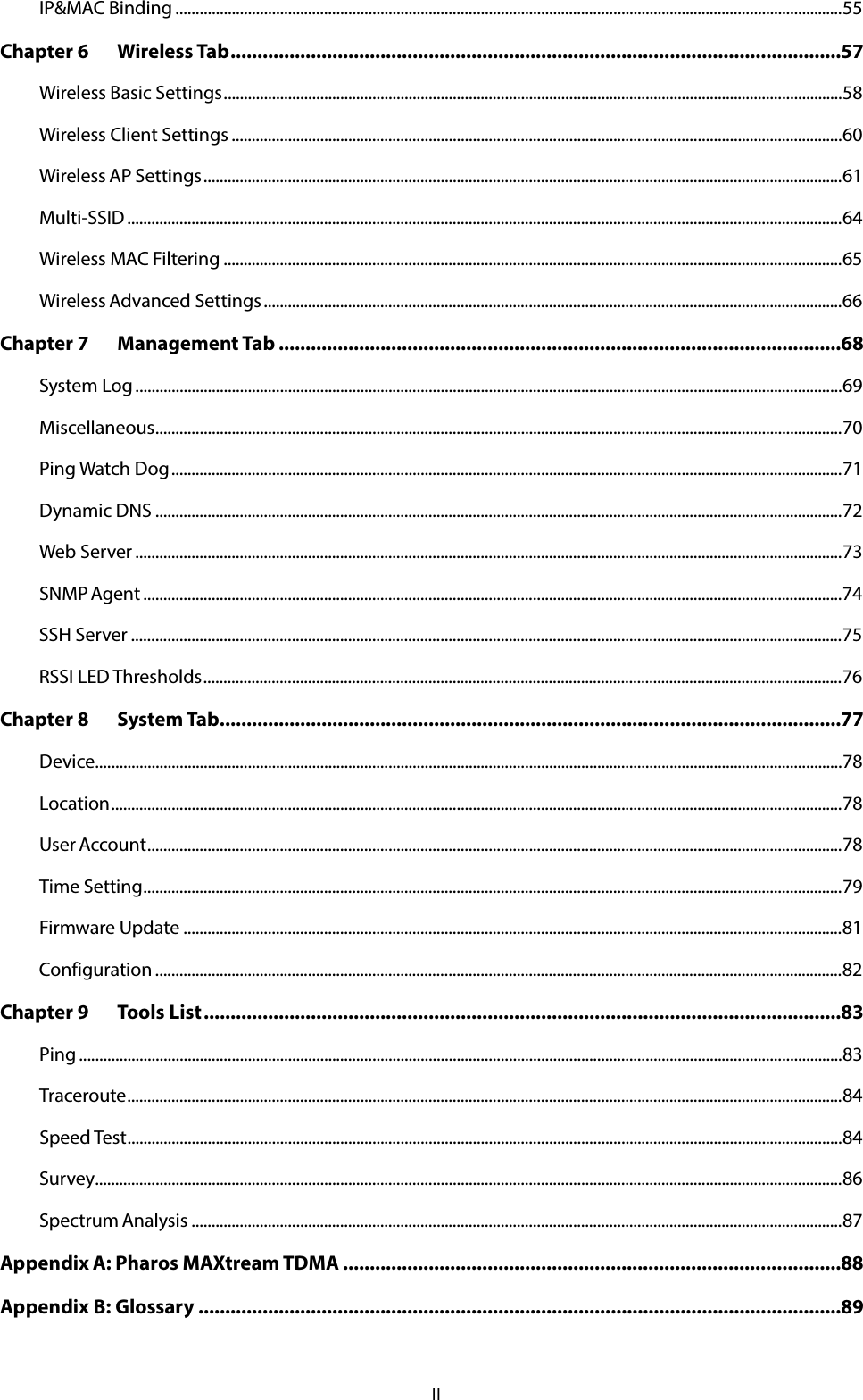
Contents
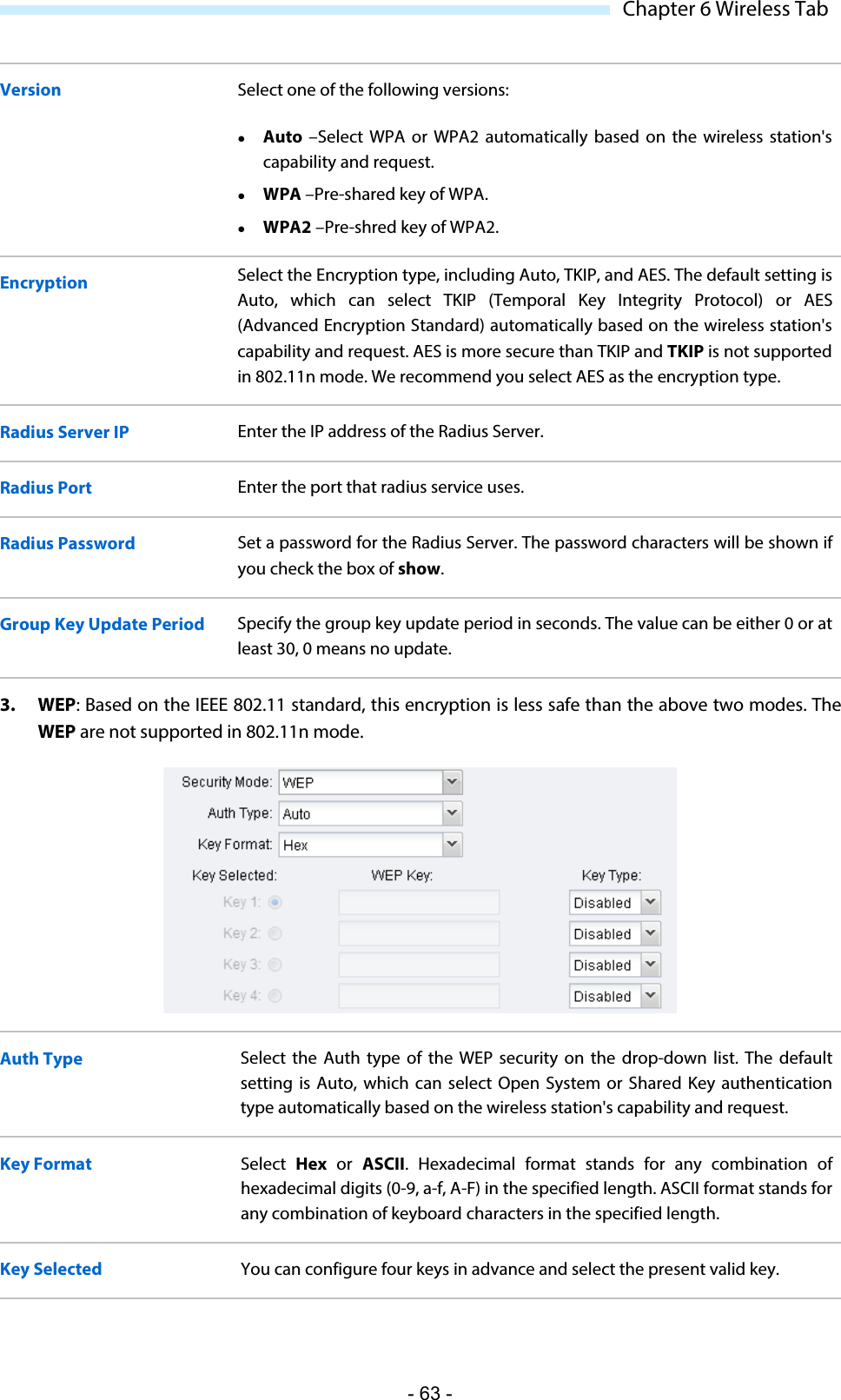
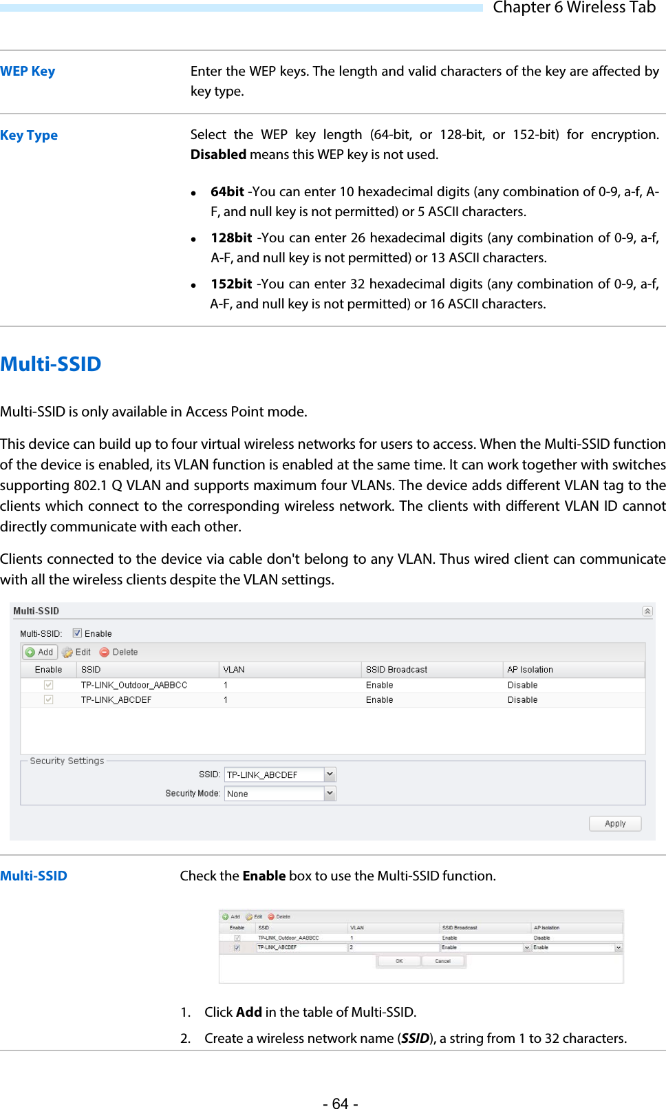
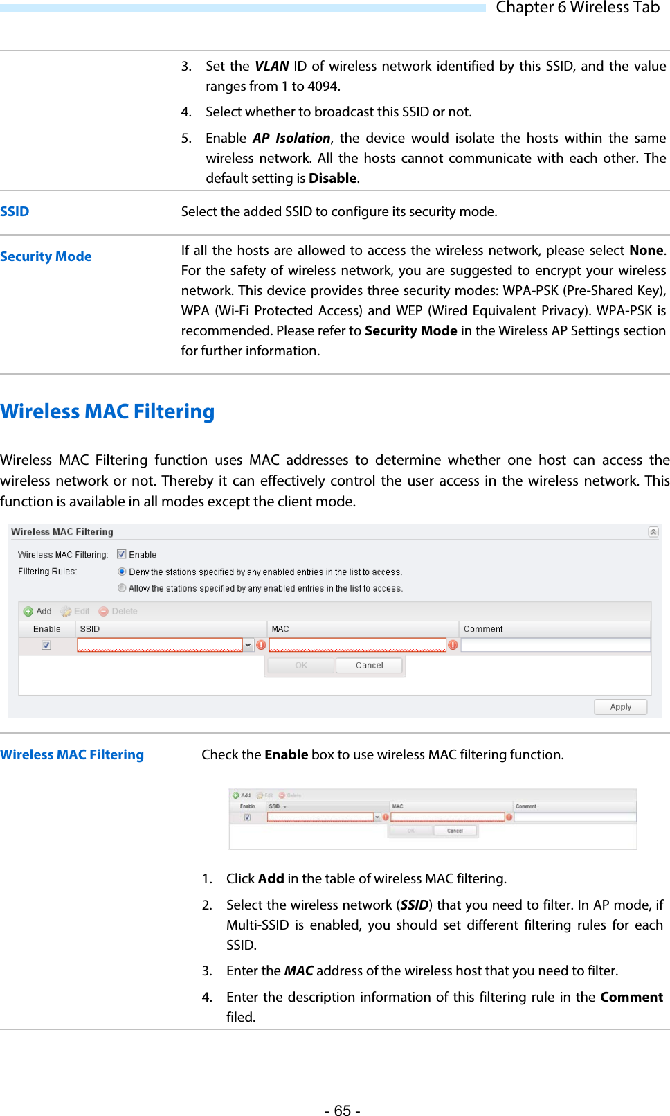
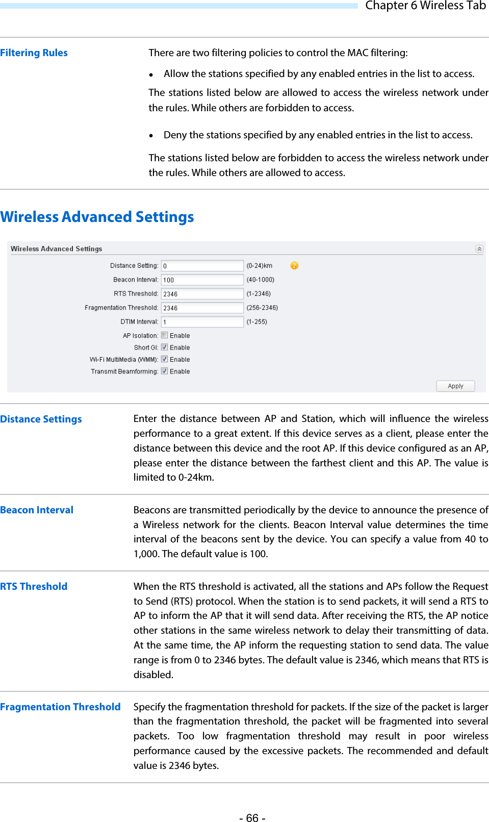
- 1. WBS210-User Manual-1-2016-06-29
- 2. WBS210-User Manual-2-2016-06-29
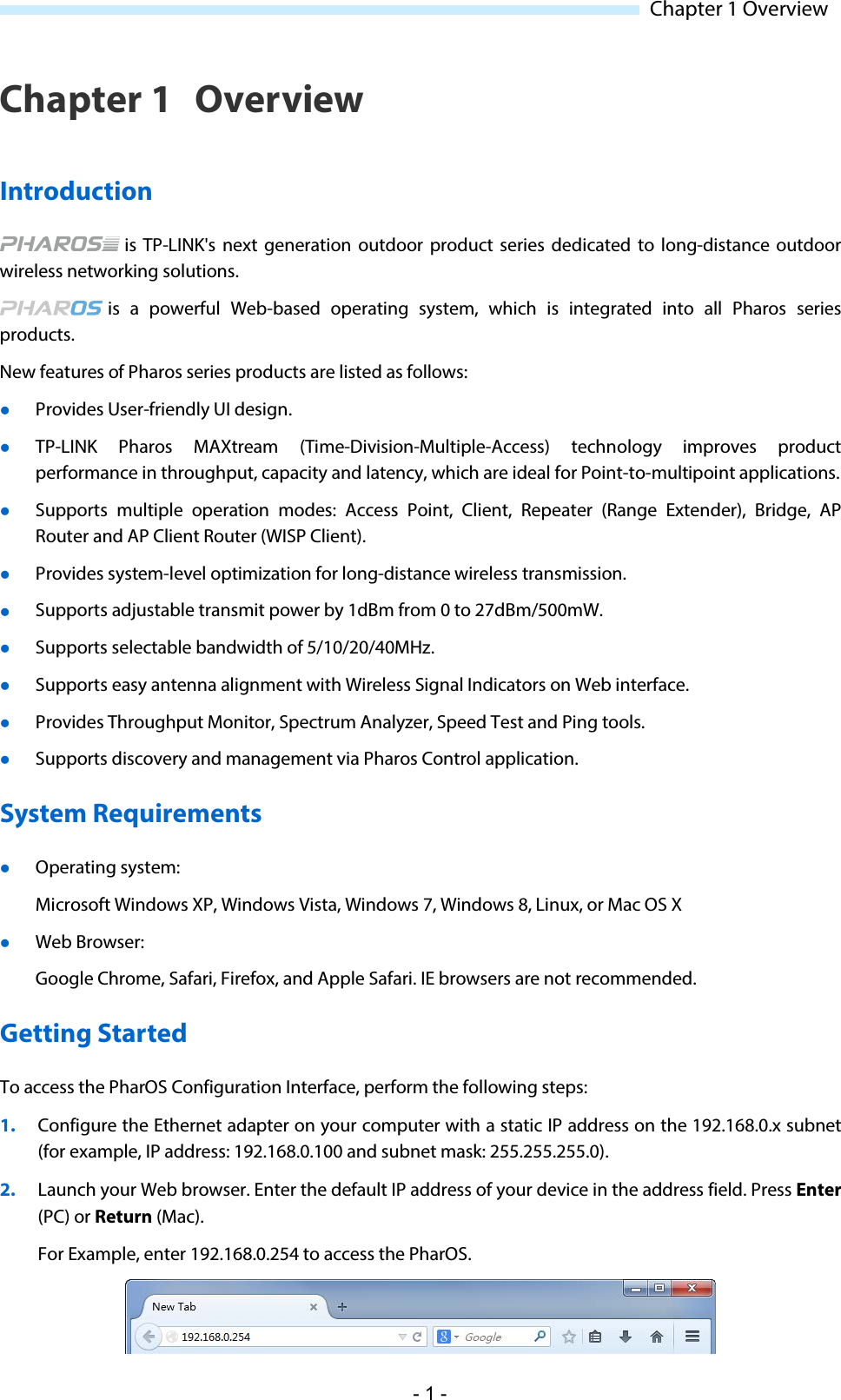
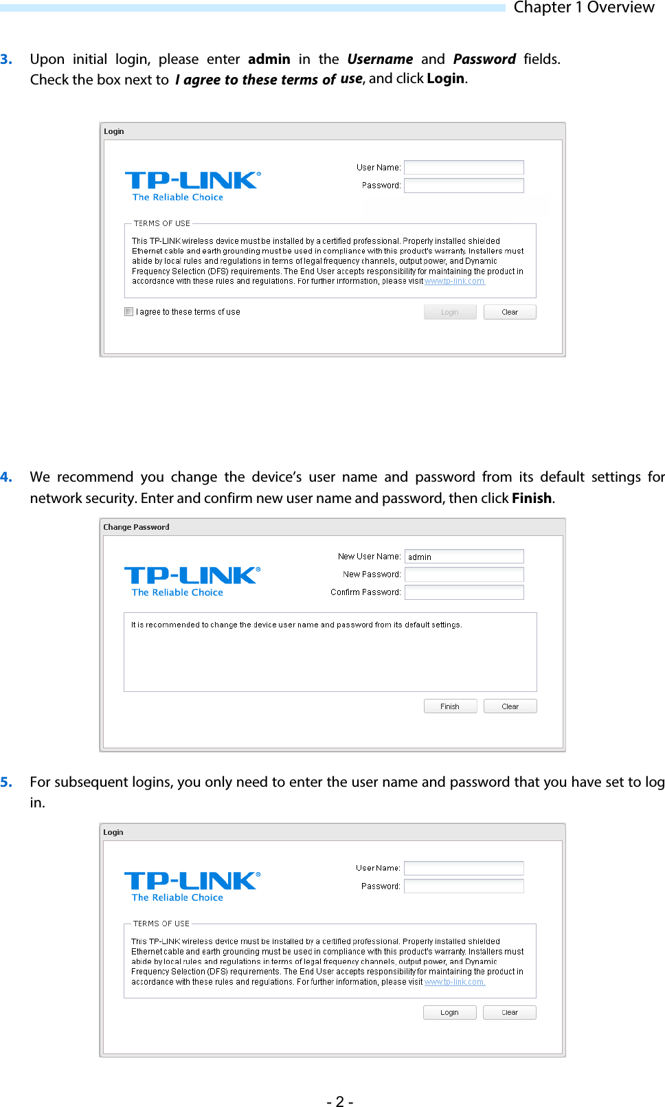
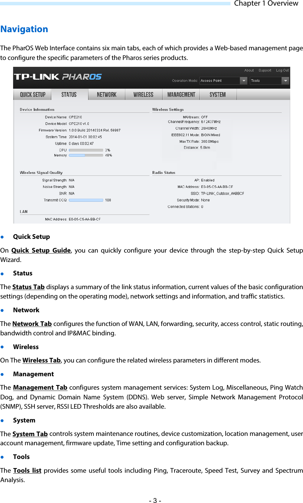
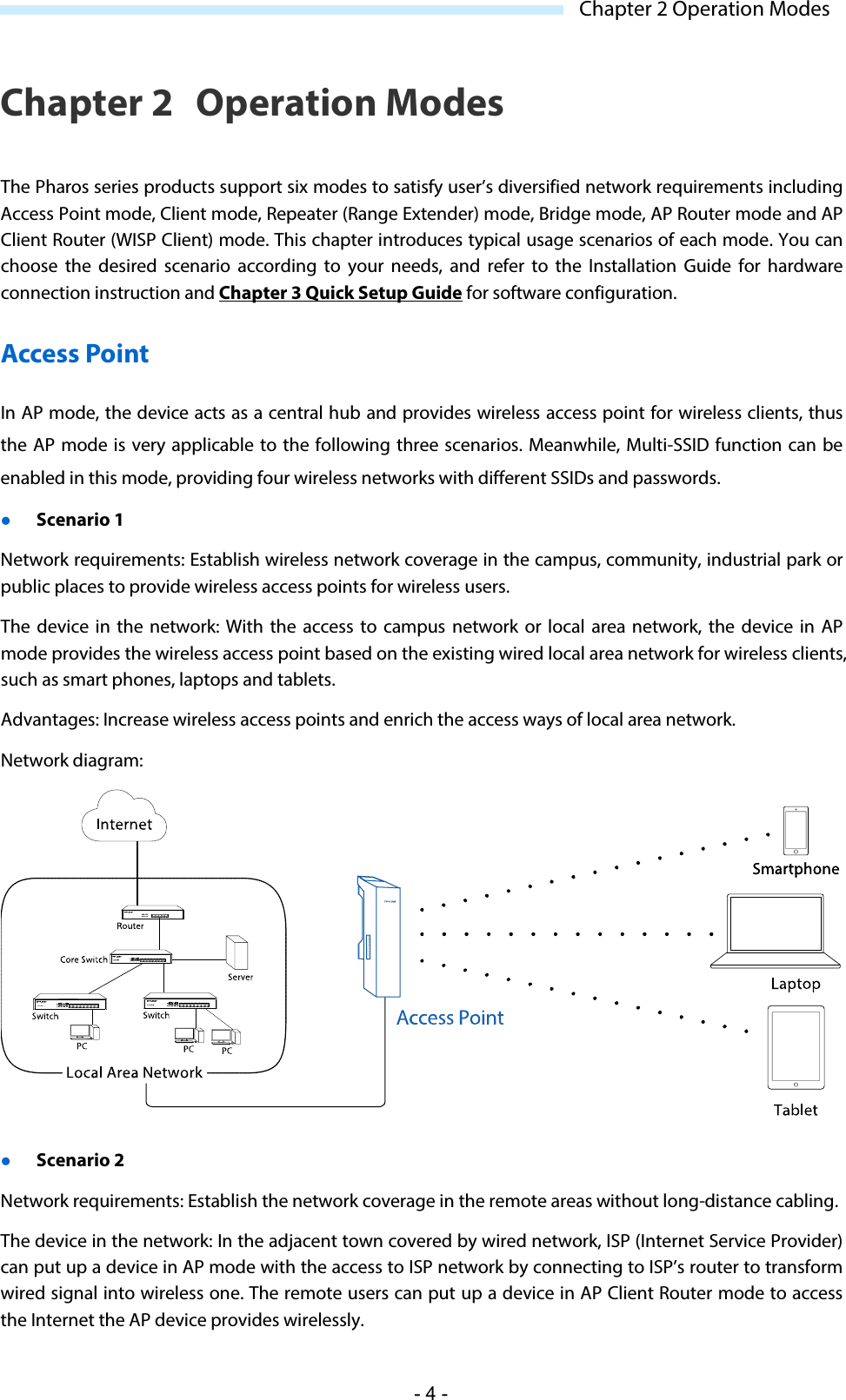
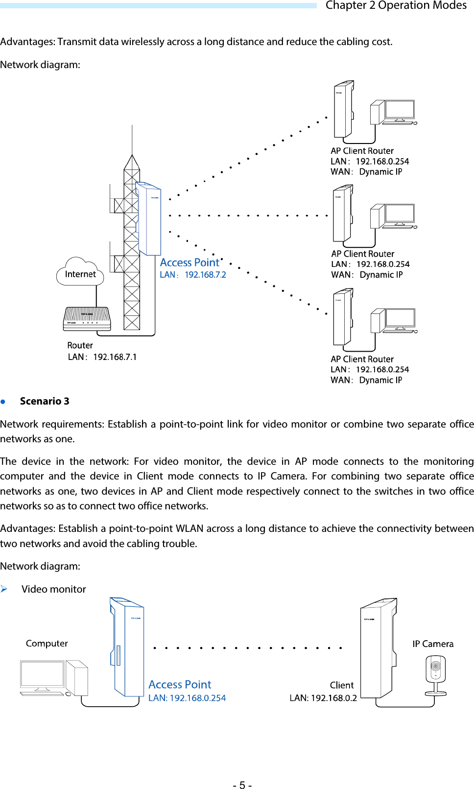
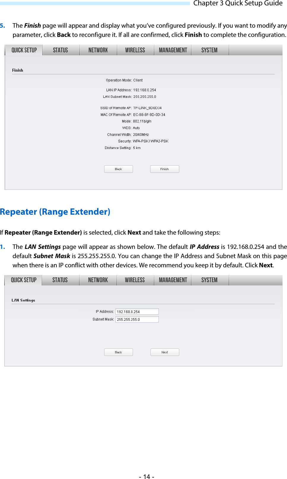
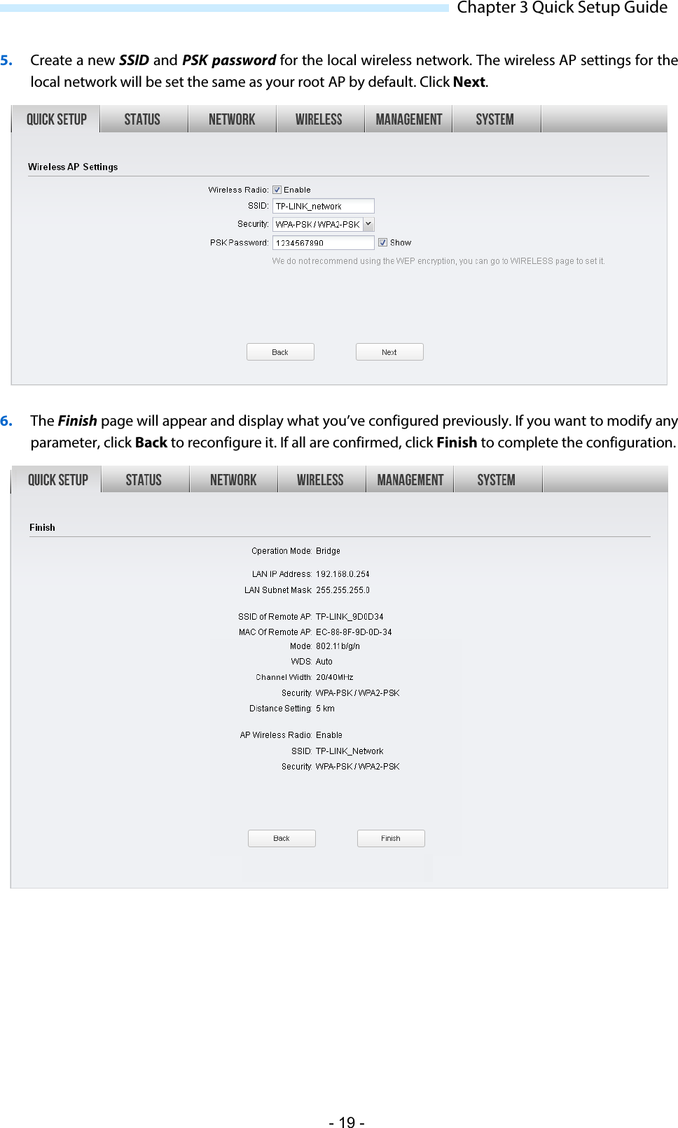
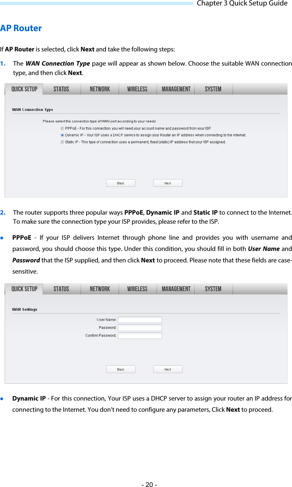
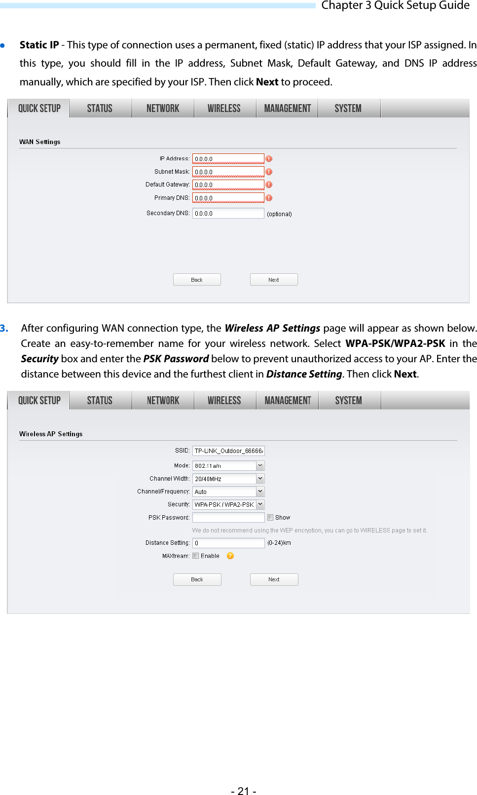
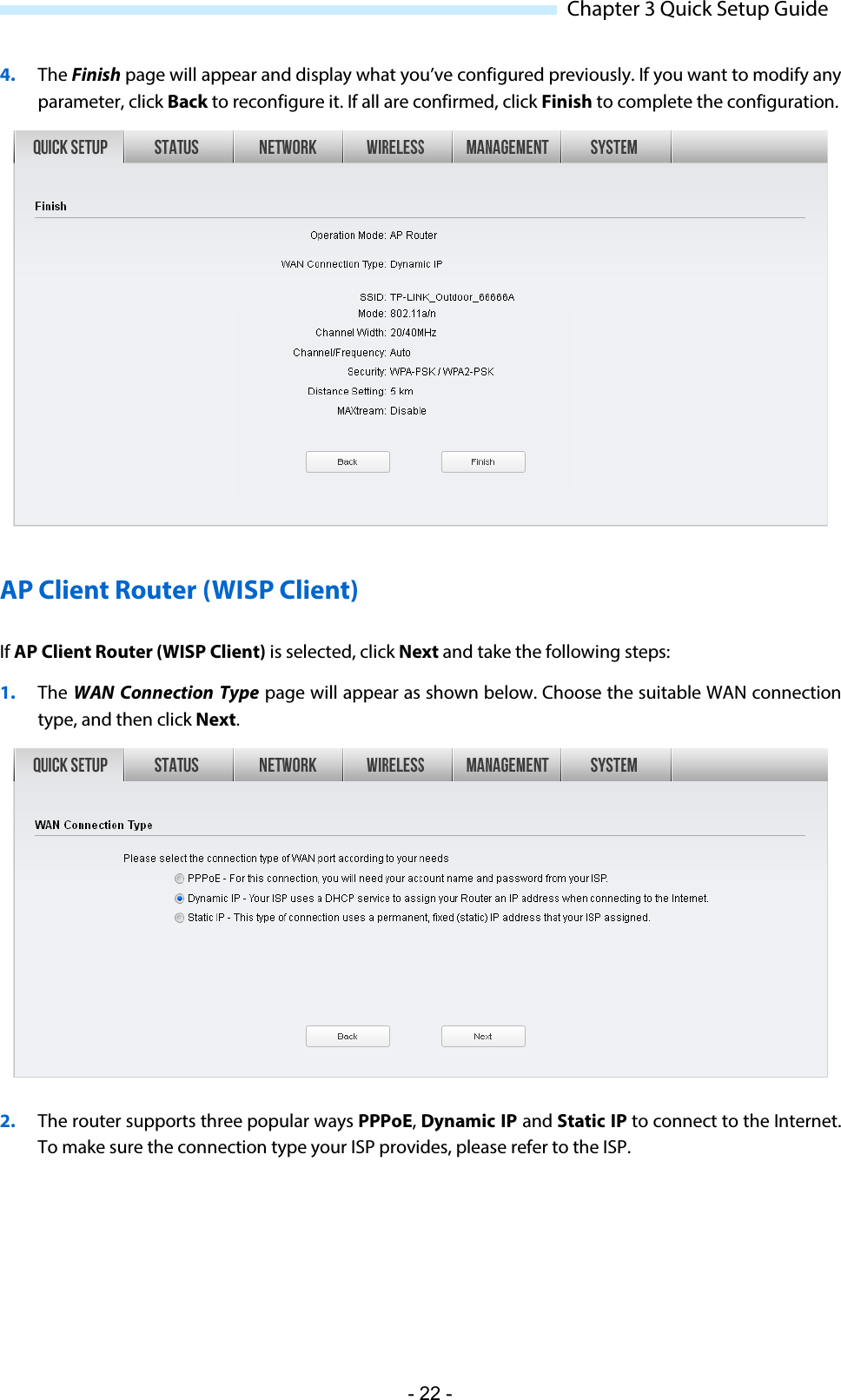
WBS210-User Manual-1-2016-06-29