TP Link Technologies WDN4800 450Mbps Wireless N Dual Band PCI Express Adapter User Manual User s manual FCC rev

TP-Link Technologies Co., Ltd. 450Mbps Wireless N Dual Band PCI Express Adapter User s manual FCC rev

Contents

User's manual-FCC_rev
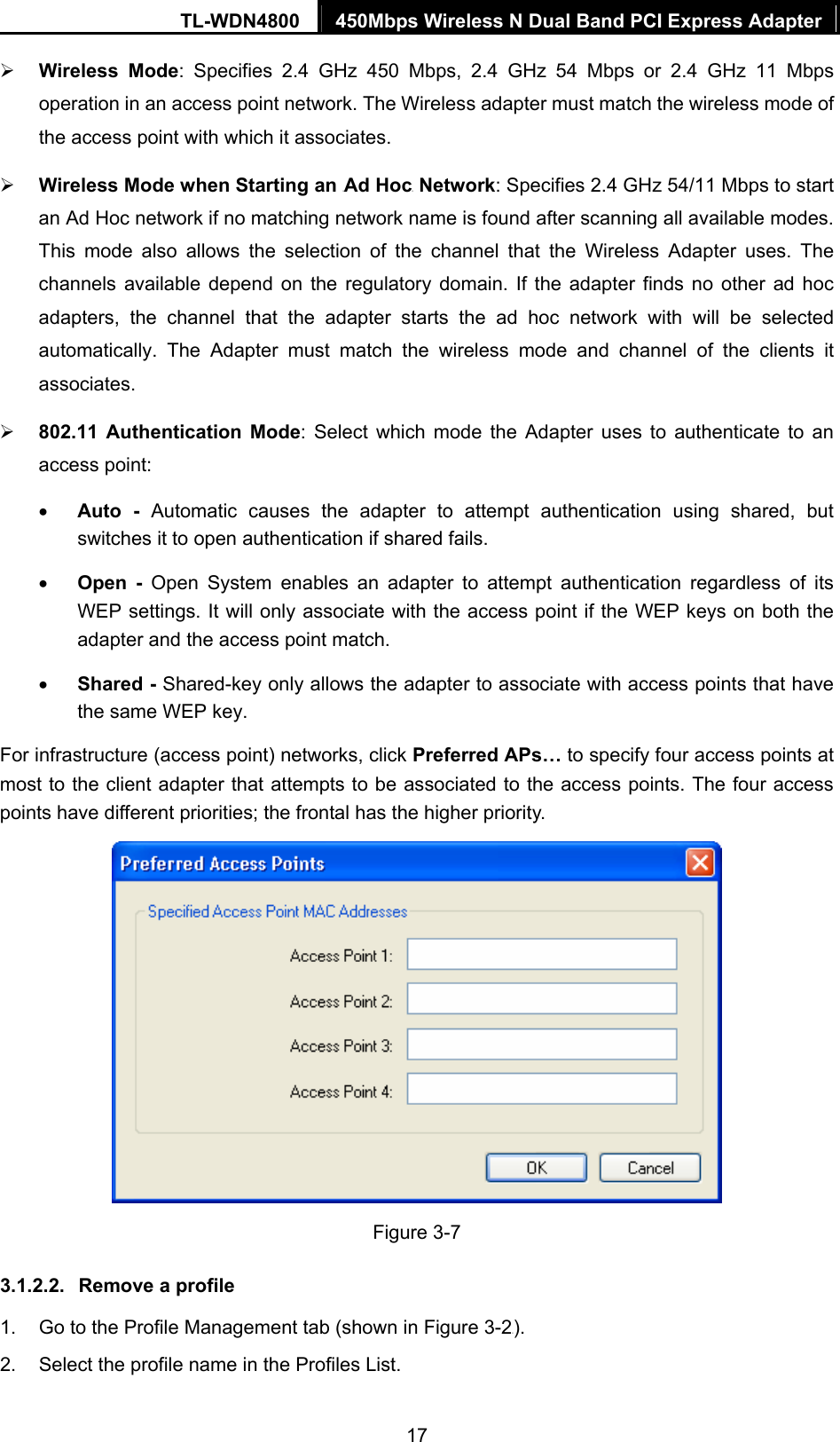
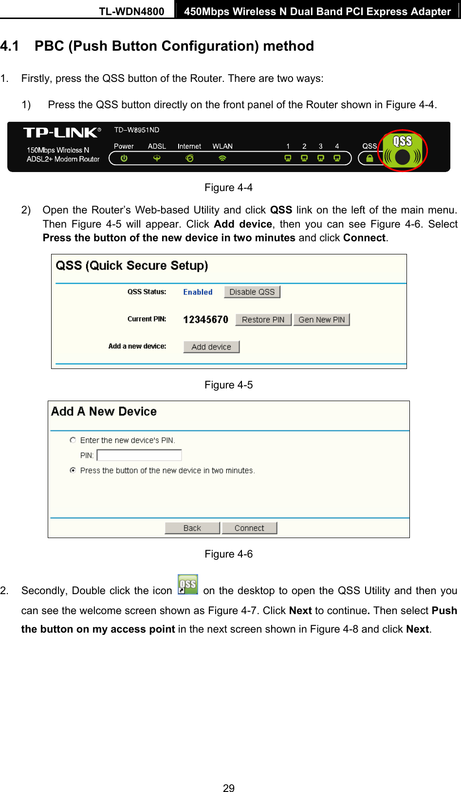
  TL-WDN4800 450Mbps Wireless N Dual Band PCI Express Adapter      Rev: 1.1.2 1910010665
  COPYRIGHT & TRADEMARKS Specifications are subject to change without notice.    is a registered trademark of TP-LINK TECHNOLOGIES CO., LTD. Other brands and product names are trademarks or registered trademarks of their respective holders. No part of the specifications may be reproduced in any form or by any means or used to make any derivative such as translation, transformation, or adaptation without permission from TP-LINK TECHNOLOGIES CO., LTD. Copyright © 2012 TP-LINK TECHNOLOGIES CO., LTD. All rights reserved. http://www.tp-link.com  FCC STATEMENT  This equipment has been tested and found to comply with the limits for a Class B digital device, pursuant to part 15 of the FCC Rules. These limits are designed to provide reasonable protection against harmful interference in a residential installation. This equipment generates, uses and can radiate radio frequency energy and, if not installed and used in accordance with the instructions, may cause harmful interference to radio communications. However, there is no guarantee that interference will not occur in a particular installation. If this equipment does cause harmful interference to radio or television reception, which can be determined by turning the equipment off and on, the user is encouraged to try to correct the interference by one or more of the following measures: •  Reorient or relocate the receiving antenna. •  Increase the separation between the equipment and receiver. •  Connect the equipment into an outlet on a circuit different from that to which the receiver is connected.   •  Consult the dealer or an experienced radio/ TV technician for help. This device complies with part 15 of the FCC Rules. Operation is subject to the following two conditions: 1)  This device may not cause harmful interference. 2)  This device must accept any interference received, including interference that may cause undesired operation. Any changes or modifications not expressly approved by the party responsible for compliance could void the user’s authority to operate the equipment.
  Note: The manufacturer is not responsible for any radio or TV interference caused by unauthorized modifications to this equipment. Such modifications could void the user’s authority to operate the equipment. Operations in the 5.15-5.25GHz band are restricted to indoor usage only. Note: The country code selection is for non-US model only and is not available to all US model. Per FCC regulation, all WiFi product marketed in US must fixed to US operation channels only. FCC RF Radiation Exposure Statement: This equipment complies with FCC RF radiation exposure limits set forth for an uncontrolled environment. This device and its antenna must not be co-located or operating in conjunction with any other antenna or transmitter. “To comply with FCC RF exposure compliance requirements, this grant is applicable to only Mobile Configurations. The antennas used for this transmitter must be installed to provide a separation distance of at least 20 cm from all persons and must not be co-located or operating in conjunction with any other antenna or transmitter.” CE Mark Warning   This is a class B product. In a domestic environment, this product may cause radio interference, in which case the user may be required to take adequate measures. National Restrictions This device is intended for home and office use in all EU countries (and other countries following the EU directive 1999/5/EC) without any limitation except for the countries mentioned below: Country Restriction Reason/remark Bulgaria None  General authorization required for outdoor use and public service France Outdoor use limited to 10 mW e.i.r.p. within the band 2454-2483.5 MHz Military Radiolocation use. Refarming of the 2.4 GHz band has been ongoing in recent years to allow current relaxed regulation. Full implementation planned 2012 Italy None  If used outside of own premises, general authorization is required
  Luxembourg None  General authorization required for network and service supply(not for spectrum) Norway Implemented This subsection does not apply for the geographical area within a radius of 20 km from the centre of Ny-Ålesund Russian Federation  None  Only for indoor applications Note: Please don’t use the product outdoors in France.  Industry Canada Statement: This device complies with RSS-210 of the Industry Canada Rules. Operation is subject to the following two conditions: (1)This device may not cause harmful interference, and   (2)This device must accept any interference received, including interference that may cause undesired operation. IMPORTANT NOTE: Radiation Exposure Statement: This equipment complies with Canada radiation exposure limits set forth for an uncontrolled environment. This equipment should be installed and operated with minimum distance 20cm between the radiator & your body. Ce dispositif est conforme à la norme CNR-210 d’Industrie Canada applicable aux appareils radio exempts de licence. Son fonctionnement est sujet aux deux conditions suivantes: (1) Le dispositif ne doit pas produire de brouillage préjudiciable, et   (2) Ce dispositif doit accepter tout brouillage reçu,y compris un brouillage susceptible de provoquer un fonctionnement indésirable. NOTE IMPORTANTE:   Déclaration d’exposition aux radiations: Cet équipement est conforme aux limites d’exposition aux rayonnements IC établies pour un environnement non contrôlé. Cet équipement doit être installé et utilisé avec un minimum de 20 cm de distance entre la source de rayonnement et votre corps.   Caution :  (i) the device for operation in the band 5150-5250 MHz is only for indoor use to reduce the potential for harmful interference to co-channel mobile satellite systems;   (ii) high-power radars are allocated as primary users (i.e. priority users) of the bands 5250-5350 MHz and 5650-5850 MHz and that these radars could cause interference and/or damage to LE-LAN devices.
  Avertissement:  (i) les dispositifs fonctionnant dans la bande 5 150-5 250 MHz sont réservés uniquement pour une utilisation à l’intérieur afin de réduire les risques de brouillage préjudiciable aux systèmes de satellites mobiles utilisant les mêmes canaux;   (ii) De plus, les utilisateurs devraient aussi être avisés que les utilisateurs de radars de haute puissance sont désignés utilisateurs principaux (c.-à-d., qu’ils ont la priorité) pour les bandes 5 250-5 350 MHz et 5 650-5 850 MHz et que ces radars pourraient causer du brouillage et/ou des dommages aux dispositifs LAN-EL.    This device has been designed to operate with the antennas listed below, and having a maximum gain of 2 dBi. Antennas not included in this list or having a gain greater than 2 dBi are strictly prohibited for use with this device. The required antenna impedance is 50 ohms.   Under Industry Canada regulations, this radio transmitter may only operate using an antenna of a type and maximum (or lesser) gain approved for the transmitter by Industry Canada. To reduce potential radio interference to other users, the antenna type and its gain should be so chosen that the equivalent isotropically radiated power (e.i.r.p.) is not more than that permitted for successful communication.” Ce dispositif a été conçu pour fonctionner avec une antenne ayant un gain maximal de 2 dB. Une antenne à gain plus élevé est strictement interdite par les règlements d'Industrie Canada. L'impédance d'antenne requise est de 50 ohms.   Conformément à la réglementation d'Industrie Canada, le présent émetteur radio peutfonctionner avec une antenne d'un type et d'un gain maximal (ou inférieur) approuvé pourl'émetteur par Industrie Canada. Dans le but de réduire les risques de brouillage radioélectriqueà l'intention des autres utilisateurs, il faut choisir le type d'antenne et son gain de sorte que lapuissance isotrope rayonnée équivalente (p.i.r.e.) ne dépasse pas l'intensité nécessaire àl'établissement d'une communication satisfaisante.    Korea Warning Statements: 당해 무선설비는 운용중 전파혼신 가능성이 있음.  NCC Notice: 經型式認證合格之低功率射頻電機,非經許可,公司、商號或使用者均不得擅自變更頻率、加大功率或變更原設計之特性及功能。 低功率射頻電機之使用不得影響飛航安全及干擾合法通信;經發現有干擾現象時,應立即停用,並改善至無干擾時方得繼續使用。前項合法通信,指依電信法規定作業之無線電通信。低功率射頻電
  機須忍受合法通信或工業、科學及醫療用電波輻射性電機設備之干擾。  Продукт сертифіковано згідно с правилами системи УкрСЕПРО на відповідність вимогам нормативних документів та вимогам,  що передбачені чинними законодавчими актами України.
 TP-LINK TECHNOLOGIES CO., LTD  TP-LINK TECHNOLOGIES CO., LTD. Building 24 (floors 1, 3, 4, 5), and 28 (floors 1-4) Central Science and Technology Park, Shennan Rd, Nanshan, Shenzhen, China DECLARATION OF CONFORMITY For the following equipment: Product Description: 450Mbps Wireless N Dual Band PCI Express Adapter Model No.: TL-WDN4800 Trademark: TP-LINK   We declare under our own responsibility that the above products satisfy all the technical regulations applicable to the product within the scope of Council Directives:     Directives 1999/5/EC, Directives 2006/95/EC, Directives 1999/519/EC, Directives 2011/65/EU The above product is in conformity with the following standards or other normative documents: ETSI EN 300 328 V1.7.1: 2006 ETSI EN 301 489-1 V1.8.1:2008 & ETSI EN 301 489-17 V2.1.1:2009 EN60950-1:2006+A11:2009+A1:2010+A12:2011  EN62311:2008   EN 301 893 The product carries the CE Mark:  Person is responsible for marking this declaration:  Yang Hongliang Product Manager of International Business   Date of issue: 2012
  CONTENTS Package Contents .................................................................................................... 1 Chapter 1. Introduction ........................................................................................ 2 1.1 Overview of the product...................................................................................................... 2 1.2 Features ............................................................................................................................. 2 1.3 LED Status ......................................................................................................................... 3 Chapter 2. Installation Guide ............................................................................... 4 2.1 Hardware Installation.......................................................................................................... 4 2.2 Software Installation ........................................................................................................... 4 Chapter 3. Configuration Guide......................................................................... 10 3.1 For Windows XP............................................................................................................... 10 3.1.1 Current Status ........................................................................................................... 10 3.1.2 Profile Management .................................................................................................. 12 3.1.3 Diagnostics................................................................................................................ 21 3.2 For Windows Vista............................................................................................................ 22 3.3 For Windows 7 ................................................................................................................. 24 Chapter 4. QSS Configuration ........................................................................... 27 4.1 PBC (Push Button Configuration) method ........................................................................ 29 4.2 PIN method ...................................................................................................................... 31 4.2.1 Enter a PIN into your AP device................................................................................ 31 4.2.2 Enter the PIN from your AP device............................................................................ 32 Appendix A: Specifications................................................................................... 34 Appendix B: Glossary............................................................................................ 35
TL-WDN4800  450Mbps Wireless N Dual Band PCI Express Adapter 1 Package Contents The following contents should be found in your box: ¾ One TL-WDN4800 450Mbps Wireless N Dual Band PCI Express Adapter ¾ Quick Installation Guide ¾ One Resource CD for TL-WDN4800, including: •  TP-LINK Wireless Configuration Utility (TWCU) and Drivers •  Quick Secure Setup (QSS) • User Guide •  Other Helpful Information ) Note: Make sure that the package contains the above items. If any of the listed items is damaged or missing, please contact with your distributor. Conventions The “Adapter” mentioned in this user guide stands for TL-WDN4800 450Mbps Wireless N Dual Band PCI Express Adapter without any explanations.
TL-WDN4800  450Mbps Wireless N Dual Band PCI Express Adapter 2 Chapter 1.  Introduction 1.1  Overview of the product The adapter is designed to provide a high-speed and unrivaled wireless performance for your notebook and PC. With a faster wireless connection, you can get a better Internet experience, such as downloading, gaming, video streaming and so on. The TL-WDN4800’s auto-sensing capability allows high packet transfer rate of up to 450Mbps for maximum throughput. It has good capability on anti-jamming; it can also interoperate with other wireless (802.11a/b/g/n) products. The adapter supports WEP, WPA and WPA2 encryption to prevent outside intrusion and protect your personal information from being exposed. The Quick Setup Wizard guides you step-by-step through the installation process; the TP-LINK Wireless Configuration Utility helps you create a wireless connection immediately. With unmatched wireless performance, reception, and security protection, the TL-WDN4800 is the best choice for easily adding or upgrading wireless connectivity. 1.2  Features ¾  IEEE802.11a, IEEE802.11b, IEEE802.11g, IEEE802.11n standards ¾  Supports WPA/WPA2 data security, IEEE802.1x authentication, TKIP/AES encryption, WEP encryption ¾  Make use of IEEE 802.11n wireless technology to provide a wireless data rate of up to 450Mbps  ¾  supports automatically adjust to lower speeds due to distance or other operating limitations ¾  Provides PCI Express interface ¾  Supports Ad-Hoc and Infrastructure modes ¾  Good capability on anti-jamming ¾  Supports roaming between access points when configured in Infrastructure mode ¾  Ease to configure and provides monitoring information ¾  Supports Windows XP, Windows Vista and Windows 7
TL-WDN4800  450Mbps Wireless N Dual Band PCI Express Adapter 3 1.3  LED Status Status Working Status Off The driver has not been installed. Flashing Slowly   The driver has been installed but there is no data being transmitted or received. Flashing Quickly   There is data being transmitted or received.
TL-WDN4800  450Mbps Wireless N Dual Band PCI Express Adapter 4 Chapter 2.  Installation Guide Please install the PCI Express adapter into your computer before installing the driver software from the Resource CD. 2.1  Hardware Installation 1.  Turn off your computer and unplug the power cord from the computer. 2.  Open the case and locate an available PCI Express slot. Remove the metal slot cover on the back of the PC. Keep the screws. Turn to your computer manufacturer for instructions if needed. 3.  Insert the PCI Express adapter into the PCI Express slot. Make sure that all of its pins have touched the slot's contacts. Once the adapter has been firmly inserted, screw its fastening tab. Then, close your PC case. 4.  Insert the power cable back into the computer and turn on your computer. ) Note: The promoted Found New Hardware Wizard screen will pop up when the adapter is installed correctly. Click Cancel. 2.2  Software Installation The adapter’s Setup Wizard will guide you through the installation procedures for Windows 7, Windows Vista, and Windows XP. The procedures in different systems are quite similar, therefore here takes the procedures in Windows XP for example. 1.  Insert the Resource CD into your CD-ROM drive, and the Figure 2-1 will appear.    Figure 2-1
TL-WDN4800  450Mbps Wireless N Dual Band PCI Express Adapter 5 2.  To continue, select the TL-WDN4800.There will be a menu including: Install Driver&Utility, Install QSS and User Guide.  Figure 2-2 3. Click Install Driver&Utility in the above Figure 2-2 to load the following screen.  Figure 2-3 4.  After a few moments Figure 2-4 will appear. Click Next to continue.
TL-WDN4800  450Mbps Wireless N Dual Band PCI Express Adapter 6  Figure 2-4 5.  After that, you should choose a Setup type. It is recommended that you select Install Client Utilities and Driver. Click Next to continue.  Figure 2-5 6. Click Browse... to change the destination location for the software. It’s recommended that you leave it default; then click Next in the screen below (shown in Figure 2-6).
TL-WDN4800  450Mbps Wireless N Dual Band PCI Express Adapter 7  Figure 2-6 7.  After that, select the program folder. You can create a new folder name or select one from the Existing Folders list. It is recommended that you keep the default setting. Click Next to continue the installation.  Figure 2-7
TL-WDN4800  450Mbps Wireless N Dual Band PCI Express Adapter 8 8.  Choose configuration tool; if you are not sure, please leave it default. Then click Next to continue.  Figure 2-8 9.  Wait a while for the installation as shown in Figure 2-9.  Figure 2-9
TL-WDN4800  450Mbps Wireless N Dual Band PCI Express Adapter 9 10.  After all the steps above, you will see the screen below; click Finish to reboot your computer.  Figure 2-10
TL-WDN4800  450Mbps Wireless N Dual Band PCI Express Adapter 10 Chapter 3.  Configuration Guide 3.1  For Windows XP In Windows XP, TP-LINK TL-WDN4800 can be configured by TP-LINK Wireless Configuration Utility (TWCU). This chapter describes how to configure your Adapter for wireless connectivity on your Wireless Local Area Network (WLAN) and use the data security encryption features.   After Installing the Adapter, the Adapter’s tray icon    will appear in your system tray. It appears at the bottom of the screen, and shows the signal strength using color and the received signal strength indication (RSSI).  If the icon is gray, there is no connection.   If the icon is red, there is poor signal strength and the RSSI is less than 5dB.   If the icon is yellow, there is poor signal strength and the RSSI is between 5dB and 10dB.   If the icon is green, there is good signal strength and the RSSI is between 10dB and 20dB.   If the icon is green, there is excellent signal strength and the RSSI is more than 20dB. Double-click the icon and the TWCU will run. You can also run the utility by clicking the Start → All Programs → TP-LINK → TP-LINK Wireless Configuration Utility. The TWCU provides some integrated and easy tools to: ¾  Display current status information ¾  Edit and add configuration profiles ¾  Display current diagnostics information The section below introduces these above capabilities. 3.1.1  Current Status The Current Status tab contains general information about the program and its operations. The Current Status tab needn’t any configurations.
TL-WDN4800  450Mbps Wireless N Dual Band PCI Express Adapter 11  Figure 3-1 The following table describes the items found on the Current Status screen. ¾ Profile Name - This shows the name of current selected configuration profile. The configuration of Profile name will be described on the General tab of Profile Management.  ¾ Link Status - This shows whether the station is associated to the wireless network. ¾ Wireless Mode - Here displays the wireless mode. ¾ Network Type - The type of network and the station currently connected are shown here. The options include: •  Infrastructure (access point) • Ad Hoc ) Note: You can configure the network type and wireless mode on the Advanced tab of Profile Management. ¾ IP Address - This displays the computer’s IP address. ¾ Control Channel - This shows the currently connected channel. ¾ Data Encryption - Here displays the encryption type the driver is using. You can configure it on the Security tab of Profile Management. ¾ Server Based Authentication - This shows whether the server based authentication is used.
TL-WDN4800  450Mbps Wireless N Dual Band PCI Express Adapter 12 ¾ Signal Strength - This shows the strength of the signal. Click Advanced on the screen above, you can see advanced information about the program and its operations. 3.1.2  Profile Management Click the Profile Management tab of the TWCU and the next screen will appear (shown in Figure 3-2X). The Profile Management screen provides tools to: ¾  Add a new profile ¾  Modify a profile ¾  Remove a profile ¾  Activate a Profile ¾  Import a Profile ¾  Export a Profile ¾  Scan Available Networks ¾ Order profiles  Figure 3-2 3.1.2.1.  Add or Modify a Configuration Profile To add a new configuration profile, click New on the Profile Management tab. To modify a configuration profile, select the configuration profile from the Profile list and click Modify. Then you will see the Management dialog box (shown in Figure 3-3).
TL-WDN4800  450Mbps Wireless N Dual Band PCI Express Adapter 13 1.  Edit the General tab ¾ Profile Name - Please enter the Profile name which identifies the configuration profile. This name must be unique. Note that the profile names are not case-sensitive. ¾ Client Name - Please enter a name which identifies the client machine. ¾ Network Names (SSIDs) - Please enter the IEEE 802.11 wireless network name. This field has a maximum limit of 32 characters.  Figure 3-3 2.  Edit the Security tab Select the Security tab in the screen above, and then you can edit the fields to configure the profile. To define the security mode, select the radio button of the desired security mode as follows.
TL-WDN4800  450Mbps Wireless N Dual Band PCI Express Adapter 14  Figure 3-4 ¾ WPA/WPA2: Wi-Fi Protected Access ¾ WPA/WPA2 Passphrase: Wi-Fi Protected Access Passphrase ¾ 802.1x: Enables 802.1x security. ¾ Pre-Shared Key (Static WEP): Enables the use of shared keys that are defined on both the access point and the station. To define shared encryption keys, choose the Shared Key radio button and click Configure to fill in the Define Shared Keys window (shown in Figure 3-5X). ) Note: The WEP security mode is not available for 802.11n. ¾ None: No security (not recommended). ) Note: If the access point which the Adapter is associated has WEP set and the client has WEP enabled, make sure that Allow Association to Mixed Cells is checked on the Security tab to allow association. To complete WEP encryption configuration, you must select the 802.11 Authentication Mode as appropriate on the Advanced tab of this Profile Management dialog. To configure the Encryption Keys under the Pre-Shared keys (Static WEP) Security mode:
TL-WDN4800  450Mbps Wireless N Dual Band PCI Express Adapter 15  Figure 3-5 ) Note: Select different Security Options, the configurations are different; you can select the appropriate security option and configure the exact key as your need. 3.  Edit the Advanced tab This screen below allows you to make advanced configuration for the profile.
TL-WDN4800  450Mbps Wireless N Dual Band PCI Express Adapter 16  Figure 3-6 ¾ Power Save Mode - Please select the power save mode in the drop-down list. • Maximum - Selects maximum mode to let the access point buffer incoming messages for the Adapter. The Adapter will detect the access point if any messages are waiting periodically. • Normal - Normal mode uses maximum when retrieving a large number of packets, then switches back to power save mode after retrieving the packets. • Off - Turns power saving off, thus powering up the Wireless PCI Express Adapter continuously for a short message response time. ¾ Network Type: There are basically two modes of networking: • Infrastructure - All wireless clients will connect to an access point or wireless Router. • Ad-Hoc - Directly connecting to another computer, for peer-to-peer communication, using wireless network adapters on each computer, such as two or more TL-WDN4800 wireless adapters. ) Note: 1)  An Infrastructure network contains an Access Point or wireless Router. All the wireless devices or clients will connect to the wireless Router or access point. 2)  An Ad-Hoc network contains only clients, such as laptops with wireless desktop adapters. All the adapters must be in Ad-Hoc mode to communicate.
TL-WDN4800  450Mbps Wireless N Dual Band PCI Express Adapter 17 ¾ Wireless Mode: Specifies 2.4 GHz 450 Mbps, 2.4 GHz 54 Mbps or 2.4 GHz 11 Mbps operation in an access point network. The Wireless adapter must match the wireless mode of the access point with which it associates. ¾ Wireless Mode when Starting an HAd HocHH Network: Specifies 2.4 GHz 54/11 Mbps to start an Ad Hoc network if no matching network name is found after scanning all available modes. This mode also allows the selection of the channel that the Wireless Adapter uses. The channels available depend on the regulatory domain. If the adapter finds no other ad hoc adapters, the channel that the adapter starts the ad hoc network with will be selected automatically. The Adapter must match the wireless mode and channel of the clients it associates. ¾ 802.11 Authentication Mode: Select which mode the Adapter uses to authenticate to an access point: • Auto - Automatic causes the adapter to attempt authentication using shared, but switches it to open authentication if shared fails. • Open - Open System enables an adapter to attempt authentication regardless of its WEP settings. It will only associate with the access point if the WEP keys on both the adapter and the access point match. • Shared - Shared-key only allows the adapter to associate with access points that have the same WEP key. For infrastructure (access point) networks, click Preferred APs… to specify four access points at most to the client adapter that attempts to be associated to the access points. The four access points have different priorities; the frontal has the higher priority.  Figure 3-7 3.1.2.2.  Remove a profile 1.  Go to the Profile Management tab (shown in Figure 3-2X). 2.  Select the profile name in the Profiles List.
TL-WDN4800  450Mbps Wireless N Dual Band PCI Express Adapter 18 3. Click Remove. ) Note: The profile being used can’t be removed. 3.1.2.3.  Switch another Profile 1.  Go to the Profile Management screen (shown in Figure 3-2X). 2.  Select the profile name required in the Profiles List. 3. Click Activate. 3.1.2.4.  Export a Profile 1.  From the Profile Management screen (shown in Figure 3-2X), highlight the profile to export. 2. Click Export…, the Export Profile window will then appear below. 3.  Browse the directory to export the profile to. 4. Click Save. The profile should then be exported to the specified location.  Figure 3-8 3.1.2.5.  Import a Profile 1.  From the Profile Management screen (shown in Figure 3-2), click Import…. Then the Import Profile will appear below. 2.  Browse to the directory where the profile is located. 3.  Highlight the profile name. 4. Click Open, the imported profile will then appear in the Profiles List.
TL-WDN4800  450Mbps Wireless N Dual Band PCI Express Adapter 19  Figure 3-9 3.1.2.6.  Scan Available Networks 1. Click Scan on the Profile Management screen (shown in Figure 3-2X), the Available Infrastructure and Ad Hoc Networks window will appear below. 2. Click Refresh to refresh the list at any time. 3.  Highlight a network name and click Activate to connect to an available network. If no configuration profile exists for that network, the Profile Management window will open the General tab screen. Fill in the Profile name and click OK to create the configuration profile for that network.  Figure 3-10
TL-WDN4800  450Mbps Wireless N Dual Band PCI Express Adapter 20 3.1.2.7.  Auto Profile Selection Management The auto selection feature allows the adapter to automatically select a profile from the list of profiles and use it to connect to the network. To add a new profile into the Auto Selected Profiles list, please follow these steps. 1.  On the Profile Management screen (shown in Figure 3-2X), click Order Profiles…. 2.  The Auto Profiles Selection management window will appear (shown in Figure 3-11) with a list of all created profiles in the Available Profiles.  Figure 3-11 3.  Highlight the profiles to add to auto profile selection, and click Add. The profile will appear in the Auto Selected Profiles box. 4.  Highlight a profile in the Auto Selected Profiles box. 5. Click Move Up or Move Down as appropriate.   ) Note: The first profile in the Auto Selected Profiles box has highest priority, while the last profile has the lowest priority. 6. Click OK. 7. Check the Auto Select Profiles checkbox on the Profile Management tab (shown in Figure 3-2). ) Note: When auto profile selection is enabled by checking Auto Select Profiles on the Profile Management tab, the client adapter will scan for an available network. The profile with the highest priority and the same SSID as one of the found networks will be used to connect to the
TL-WDN4800  450Mbps Wireless N Dual Band PCI Express Adapter 21 network. If the connection fails, the client adapter will try the next highest priority profile that matches the SSID until an available network is found. 3.1.3  Diagnostics The Diagnostics tab of the TP-LINK Wireless Configuration Utility (TWCU) provides buttons used to retrieve receiving and transmitting statistics. The Diagnostics tab does not require any configuration. The Diagnostics tab lists the following receiving and transmitting diagnostics for frames received or transmitted by the wireless network adapter: ¾  Multicast frames transmitted and received   ¾  Broadcast frames transmitted and received   ¾  Unicast frames transmitted and received   ¾  Total bytes transmitted and received  Figure 3-12 3.1.3.1.  Check Driver Information Click the Adapter Information button in the screen above, you will see the adapter information, including general information about the wireless network adapter and the Network Driver Interface Specification (NDIS) driver. Access the adapter information from the Diagnostics tab. ¾ Card Name - The name of the wireless network adapter.   ¾ MAC Address - The MAC address of the wireless network adapter.   ¾ Driver - The driver name and path of the wireless network adapter driver.
TL-WDN4800  450Mbps Wireless N Dual Band PCI Express Adapter 22 ¾ Driver Version - The version of the wireless network adapter driver. ¾ Driver Date - The creation date of the wireless network adapter driver. ¾ Client Name - The name of the client computer. 3.1.3.2.  Check Receive and Transmit Statistical Information The  Advanced Statistics show receiving and transmitting statistical information about the following receiving and transmitting diagnostics for frames received by or transmitted to the wireless network adapter.  Figure 3-13 3.2  For Windows Vista After the Adapter's driver has been installed, Windows Vista will display a wireless Network Connection message like this one.  Figure 3-14
TL-WDN4800  450Mbps Wireless N Dual Band PCI Express Adapter 23 Icon    means the connection has been established. Icon    means there is no connection. To establish a connection, please follow the steps below.   1. Right-click the icon    in your system tray, then click Connect to a network.  Figure 3-15 2.  The following screen will show you available wireless networks. Highlight the one you want to join, and then click Connect.  Figure 3-16 3.  To continue, click Connect Anyway. (Click the Cancel button to end the connection.)
TL-WDN4800  450Mbps Wireless N Dual Band PCI Express Adapter 24  Figure 3-17 4.  If the connection is successfully established, the following screen will appear; click Close to complete the connection.  Figure 3-18 3.3  For Windows 7 TP-LINK Wireless Configuration Utility (TWCU) is not available for Windows 7. So after the Adapter's driver has been installed, we have to use Windows WLAN Autoconfig to establish a connection. Please follow the steps below.
TL-WDN4800  450Mbps Wireless N Dual Band PCI Express Adapter 25 1.  Click the icon    at the bottom of your screen in your system tray and then you will see the available wireless network list. Select the SSID of your Access Point and click Connect.  Figure 3-19 2.  If your wireless network is secured, you will be required to enter the security key as shown in Figure 3-20. Enter the password in the Security Key field, take 1234567890 for example. And then click OK.  Figure 3-20
TL-WDN4800  450Mbps Wireless N Dual Band PCI Express Adapter 26 3.  If the key entered is correct, you will successfully connect to the network as shown in Figure 3-21.  Figure 3-21
TL-WDN4800  450Mbps Wireless N Dual Band PCI Express Adapter 27 Chapter 4.  QSS Configuration QSS (Quick Secure Setup) function allows you to add a new wireless device to an existing network quickly. If the wireless Router supports Wi-Fi Protected Setup (WPS), you can establish a wireless connection between wireless card and Router using either Push Button Configuration (PBC) method or PIN method. ) Note: QSS function is not supported in Windows 7 OS. First of all, the QSS software should be installed. Below are the steps for the installation.   1.  Insert the Resource CD into your CD-ROM drive, and the Figure 4-1 will appear.    Figure 4-1 2.  To continue, select the TL-WDN4800.There will be a menu including: Install Driver&Utility, Install QSS and User Guide.
TL-WDN4800  450Mbps Wireless N Dual Band PCI Express Adapter 28  Figure 4-2 3. Select Install QSS in the above Figure 4-2 to load the following screen.  Figure 4-3 Then, please follow the instructions of the Operation System to complete the QSS installation. After that, QSS function can be enabled. Here we will introduce two ways to configure the QSS (For the configuration of QSS, here takes the Wireless Router of our company for example).
TL-WDN4800  450Mbps Wireless N Dual Band PCI Express Adapter 29 4.1  PBC (Push Button Configuration) method 1.  Firstly, press the QSS button of the Router. There are two ways: 1)    Press the QSS button directly on the front panel of the Router shown in Figure 4-4.  Figure 4-4 2)  Open the Router’s Web-based Utility and click QSS link on the left of the main menu. Then  Figure 4-5 will appear. Click Add device, then you can see Figure 4-6. Select Press the button of the new device in two minutes and click Connect.   Figure 4-5  Figure 4-6 2.  Secondly, Double click the icon    on the desktop to open the QSS Utility and then you can see the welcome screen shown as Figure 4-7. Click Next to continue. Then select Push the button on my access point in the next screen shown in Figure 4-8 and click Next.
TL-WDN4800  450Mbps Wireless N Dual Band PCI Express Adapter 30  Figure 4-7  Figure 4-8 3.  Then wait a minute until Figure 4-9 appears. Click Finish to complete the QSS configuration.
TL-WDN4800  450Mbps Wireless N Dual Band PCI Express Adapter 31  Figure 4-9 4.2  PIN method There are two ways to configure the QSS by PIN method: 1)  Enter a PIN into your AP device. 2)  Enter the PIN from your AP device.   Following are the detailed configuration procedures of each way.   4.2.1  Enter a PIN into your AP device 1. Double-click the icon    on the desktop to open the QSS Utility and then you can see the welcome screen shown as Figure 4-7 Click Next to continue. Figure 4-10 will appear. Select the second option and you will see the PIN value of the adapter which is randomly generated. Click Next.
TL-WDN4800  450Mbps Wireless N Dual Band PCI Express Adapter 32  Figure 4-10 2.  Open the Router’s Web-based Utility and click QSS link on the left of the main menu. Then Figure 4-5 will appear. Click Add device, then you can see XFigure 4-11X. Select Enter the new device’s PIN and enter the PIN value of the adapter shown in Figure 4-11, click Connect.  Figure 4-11 3. When Figure 4-9 appears, the QSS configuration is complete. 4.2.2  Enter the PIN from your AP device 1.  Open the QSS Utility and you will see Figure 4-7 . Click Next to continue. Then Figure 4-12 will appear. Select the third option and enter the PIN value which is labeled on the bottom of the Router. Click Next.
TL-WDN4800  450Mbps Wireless N Dual Band PCI Express Adapter 33  Figure 4-12 2. When Figure 4-9 appears, the QSS configuration is complete. ) Note: If you generate a new PIN code for your Router, please enter the new one instead.
TL-WDN4800  450Mbps Wireless N Dual Band PCI Express Adapter 34 Appendix A: Specifications Normal Interface PCI Express Interface Standards IEEE802.11a; IEEE802.11b; IEEE802.11g;   IEEE802.11n; IEEE802.1x Operating System  Windows XP / Windows Vista / Windows 7 Radio Data Rate  11a: 6/9/12/18/24/36/48/54Mbps 11b: 1/2/5.5/11Mbps 11g: 6/9/12/18/24/36/48/54Mbps 11n: Up to 450Mbps Modulation 11a: OFDM 11b: CCK, QPSK, BPSK; 11g: OFDM; 11n: QPSK, BPSK, 16-QAM, 64-QAM Media Access Protocol  CSMA/CA with ACK Data Security  64/128/152-bit  WEP; WPA/WPA2; WPA-PSK/WPA2-PSK; TKIP/AES Frequency  2.4 ~ 2.4835GHz, 5.180 ~ 5.240GHz, 5.745 ~ 5.825GHz Spread Spectrum  Direct Sequence Spread Spectrum (DSSS) Safety & Emissions  FCC, CE, IC, RoHS, Wi-Fi  Environmental and Physical Operating Temp.  0℃ ~ 40℃ (32 ~104℉℉) Storage Temp.  -40℃ ~ 70  (℃-40℉~158℉) Working Humidity  10% ~ 90% RH, Non-condensing Storage Humidity  5% ~ 90% RH, Non-condensing
TL-WDN4800  450Mbps Wireless N Dual Band PCI Express Adapter 35 Appendix B: Glossary ¾ 802.11a  - specification for wireless networking at 54 Mbps using OFDM modulation and operating in radio band at 5GHz. ¾ 802.11b - The 802.11b standard specifies a wireless product networking at 11 Mbps using direct-sequence spread-spectrum (DSSS) technology and operating in the unlicensed radio spectrum at 2.4GHz, and WEP encryption for security. 802.11b networks are also referred to as Wi-Fi networks. ¾ 802.11g - specification for wireless networking at 54 Mbps using direct-sequence spread-spectrum (DSSS) technology, using OFDM modulation and operating in the unlicensed radio spectrum at 2.4GHz, and backward compatibility with IEEE 802.11b devices, and WEP encryption for security. ¾ 802.11n - 802.11n builds upon previous 802.11 standards by adding MIMO (multiple-input multiple-output). MIMO uses multiple transmitter and receiver antennas to allow for increased data throughput via spatial multiplexing and increased range by exploiting the spatial diversity, perhaps through coding schemes like Alamouti coding. The Enhanced Wireless Consortium (EWC) [3] was formed to help accelerate the IEEE 802.11n development process and promote a technology specification for interoperability of next-generation wireless local area networking (WLAN) products. ¾ Ad-hoc Network - An ad-hoc network is a group of computers, each with a Wireless Adapter, connected as an independent 802.11 wireless LAN. Ad-hoc wireless computers operate on a peer-to-peer basis, communicating directly with each other without the use of an access point. Ad-hoc mode is also referred to as an Independent Basic Service Set (IBSS) or as peer-to-peer mode, and is useful at a departmental scale or SOHO operation.   ¾ DSSS - (Direct-Sequence Spread Spectrum) - DSSS generates a redundant bit pattern for all data transmitted. This bit pattern is called a chip (or chipping code). Even if one or more bits in the chip are damaged during transmission, statistical techniques embedded in the receiver can recover the original data without the need of retransmission. To an unintended receiver, DSSS appears as low power wideband noise and is rejected (ignored) by most narrowband receivers. However, to an intended receiver (i.e. another wireless LAN endpoint), the DSSS signal is recognized as the only valid signal, and interference is inherently rejected (ignored). ¾ FHSS - (Frequency  Hopping  Spread  Spectrum)  - FHSS continuously changes (hops) the carrier frequency of a conventional carrier several times per second according to a pseudo-random set of channels. Because a fixed frequency is not used, and only the transmitter and receiver know the hop patterns, interception of FHSS is extremely difficult. ¾ Infrastructure Network - An infrastructure network is a group of computers or other devices, each with a Wireless Adapter, connected as an 802.11 wireless LAN. In infrastructure mode, the wireless devices communicate with each other and to a wired network by first going through an access point. An infrastructure wireless network connected to a wired network is referred to as a Basic Service Set (BSS). A set of two or more BSS in a single network is
TL-WDN4800  450Mbps Wireless N Dual Band PCI Express Adapter 36 referred to as an Extended Service Set (ESS). Infrastructure mode is useful at a corporation scale, or when it is necessary to connect the wired and wireless networks.   ¾ Spread Spectrum - Spread Spectrum technology is a wideband radio frequency technique developed by the military for use in reliable, secure, mission-critical communications systems. It is designed to trade off bandwidth efficiency for reliability, integrity, and security. In other words, more bandwidth is consumed than in the case of narrowband transmission, but the trade off produces a signal that is, in effect, louder and thus easier to detect, provided that the receiver knows the parameters of the spread-spectrum signal being broadcast. If a receiver is not tuned to the right frequency, a spread-spectrum signal looks like background noise. There are two main alternatives, Direct Sequence Spread Spectrum (DSSS) and Frequency Hopping Spread Spectrum (FHSS). ¾ SSID - A  Service  Set  Identification is a thirty-two character (maximum) alphanumeric key identifying a wireless local area network. For the wireless devices in a network to communicate with each other, all devices must be configured with the same SSID. This is typically the configuration parameter for a wireless PC card. It corresponds to the ESSID in the wireless Access Point and to the wireless network name. See also Wireless Network Name and ESSID. ¾ WEP - (Wired Equivalent Privacy) - A data privacy mechanism based on a 64-bit or 128-bit or 152-bit shared key algorithm, as described in the IEEE 802.11 standard. To gain access to a WEP network, you must know the key. The key is a string of characters that you create. When using WEP, you must determine the level of encryption. The type of encryption determines the key length. 128-bit encryption requires a longer key than 64-bit encryption. Keys are defined by entering in a string in HEX (hexadecimal - using characters 0-9, A-F) or ASCII (American Standard Code for Information Interchange – alphanumeric characters) format. ASCII format is provided so you can enter a string that is easier to remember. The ASCII string is converted to HEX for use over the network. Four keys can be defined so that you can change keys easily. ¾ Wi-Fi - A trade name for the 802.11b wireless networking standard, given by the Wireless Ethernet Compatibility Alliance (WECA, see http://www.wi-fi.net), an industry standards group promoting interoperability among 802.11b devices. ¾ WLAN - (Wireless  Local  Area  Network) - A group of computers and associated devices communicate with each other wirelessly, which network serving users are limited in a local area. ¾ WPA - (Wi-Fi  Protected  Access)  - A wireless security protocol uses TKIP (Temporal Key Integrity Protocol) encryption, which can be used in conjunction with a RADIUS server.

Navigation menu