TP Link Technologies WPA8630P AC1200 Wi-Fi Range Extender,AV1200 Passthrough Powerline Edition User Manual User Manuel
TP-Link Technologies Co., Ltd. AC1200 Wi-Fi Range Extender,AV1200 Passthrough Powerline Edition User Manuel
Contents
- 1. User Manuel
- 2. User Manual
User Manuel

REV1.0.0 1910011535
TL-WPA8630P
User Guide
AV1200 Gigabit Passthrough Powerline ac
Wi-Fi Extender
Contents
About This Guide . . . . . . . . . . . . . . . . . . . . . . . . . . . . . . . . . . . . . . . . . . . . . . . . . . 1
Chapter 1. Get to Know About Your Powerline Extender. . . . . . . . . . . . . 2
1. 1. Product Overview . . . . . . . . . . . . . . . . . . . . . . . . . . . . . . . . . . . . . . . . . . . . . . . . . . . . . . . . . . 3
1. 2. Main Features . . . . . . . . . . . . . . . . . . . . . . . . . . . . . . . . . . . . . . . . . . . . . . . . . . . . . . . . . . . . . . 3
1. 3. Product Appearance . . . . . . . . . . . . . . . . . . . . . . . . . . . . . . . . . . . . . . . . . . . . . . . . . . . . . . . 4
1. 3. 1. LED Legend. . . . . . . . . . . . . . . . . . . . . . . . . . . . . . . . . . . . . . . . . . . . . . . . . . . . . . . . . . 4
1. 3. 2. Physical Interface . . . . . . . . . . . . . . . . . . . . . . . . . . . . . . . . . . . . . . . . . . . . . . . . . . . . 5
Chapter 2. Initial Use . . . . . . . . . . . . . . . . . . . . . . . . . . . . . . . . . . . . . . . . . . . . . . 7
2. 1. To Set Up a New Secure Wireless Network . . . . . . . . . . . . . . . . . . . . . . . . . . . . . . . . . . . 8
2. 2. To Extend the Existing Wireless Network . . . . . . . . . . . . . . . . . . . . . . . . . . . . . . . . . . . . 9
Chapter 3. Conguring via Web Management Interface . . . . . . . . . . . . 12
3. 1. Management Interface . . . . . . . . . . . . . . . . . . . . . . . . . . . . . . . . . . . . . . . . . . . . . . . . . . . . 13
3. 1. 1. Login . . . . . . . . . . . . . . . . . . . . . . . . . . . . . . . . . . . . . . . . . . . . . . . . . . . . . . . . . . . . . . . 13
3. 1. 2. Change the Login Account . . . . . . . . . . . . . . . . . . . . . . . . . . . . . . . . . . . . . . . . . . 13
3. 2. Manage Powerline Network . . . . . . . . . . . . . . . . . . . . . . . . . . . . . . . . . . . . . . . . . . . . . . . 14
3. 2. 1. Add a New Device to the Powerline Network. . . . . . . . . . . . . . . . . . . . . . . . . 14
3. 2. 2. Change Powerline Network Name . . . . . . . . . . . . . . . . . . . . . . . . . . . . . . . . . . . 15
3. 3. Wi-Fi Move . . . . . . . . . . . . . . . . . . . . . . . . . . . . . . . . . . . . . . . . . . . . . . . . . . . . . . . . . . . . . . . . 15
3. 4. Wi-Fi Clone. . . . . . . . . . . . . . . . . . . . . . . . . . . . . . . . . . . . . . . . . . . . . . . . . . . . . . . . . . . . . . . . 16
3. 5. Wireless Network. . . . . . . . . . . . . . . . . . . . . . . . . . . . . . . . . . . . . . . . . . . . . . . . . . . . . . . . . . 17
3. 5. 1. Customize Wireless Settings . . . . . . . . . . . . . . . . . . . . . . . . . . . . . . . . . . . . . . . . . 17
3. 5. 2. Wireless Clients . . . . . . . . . . . . . . . . . . . . . . . . . . . . . . . . . . . . . . . . . . . . . . . . . . . . . 20
3. 6. LED Schedules . . . . . . . . . . . . . . . . . . . . . . . . . . . . . . . . . . . . . . . . . . . . . . . . . . . . . . . . . . . . 20
3. 7. Schedule Your Wireless Function . . . . . . . . . . . . . . . . . . . . . . . . . . . . . . . . . . . . . . . . . . . 21
3. 8. Parental Controls . . . . . . . . . . . . . . . . . . . . . . . . . . . . . . . . . . . . . . . . . . . . . . . . . . . . . . . . . . 23
3. 9. Guest Network . . . . . . . . . . . . . . . . . . . . . . . . . . . . . . . . . . . . . . . . . . . . . . . . . . . . . . . . . . . . 25
3. 10. MAC Filter. . . . . . . . . . . . . . . . . . . . . . . . . . . . . . . . . . . . . . . . . . . . . . . . . . . . . . . . . . . . . . . . . 26
3. 11. Administration . . . . . . . . . . . . . . . . . . . . . . . . . . . . . . . . . . . . . . . . . . . . . . . . . . . . . . . . . . . . 28
3. 11. 1. LAN IP Address . . . . . . . . . . . . . . . . . . . . . . . . . . . . . . . . . . . . . . . . . . . . . . . . . . . . 28
3. 11. 2. Set Up System Time . . . . . . . . . . . . . . . . . . . . . . . . . . . . . . . . . . . . . . . . . . . . . . . . 28
3. 11. 3. Upgrade the Firmware . . . . . . . . . . . . . . . . . . . . . . . . . . . . . . . . . . . . . . . . . . . . . 30
3. 11. 4. Backup and Restore Conguration Settings . . . . . . . . . . . . . . . . . . . . . . . . . 30
3. 11. 5. System Log . . . . . . . . . . . . . . . . . . . . . . . . . . . . . . . . . . . . . . . . . . . . . . . . . . . . . . . . 32
Appendix A: Specications . . . . . . . . . . . . . . . . . . . . . . . . . . . . . . . . . . . . . . . . 33
1
About This Guide
This guide provides details of each function and shows how to configure the powerline
extender appropriate to your needs. In addition to this guide, a Quick Installation Guide
is also released with each TP-LINK powerline extender, you are suggested to configure
your extender for quick Internet setup by following the published Quick Installation
Guide before you get started with a further configuration.
Conventions
In this guide the following conventions are used:
Convention Description
Powerline extender Stands for AV1200 Gigabit Passthrough Powerline ac Wi-Fi Extender without
any explanation.
parameters
Parameters provided in the screenshots are just references for setting up the
device, which may differ from the actual situation. You can set the parameters
according to your demand.
screenshots
The demonstrated screenshots may look a little different from the actual page
of your device due to the various firmware versions. Please just configure your
product based on the actual web page.
Blue Italic Hyperlinks are in blue italic. You can click to redirect to a website or a specific
section.
Blue Contents to be emphasized and texts on screen or on the web page are in
blue, including the menus, items, buttons, etc.
>
The menu structures to show the path to load the corresponding page. For
example, Wireless > MAC Filter means the MAC Filter function page is under
the Wireless menu.
Note: Ignoring this type of note might result in a malfunction or damage to the
device.
Tips: Indicates important information that helps you make better use of your
device.
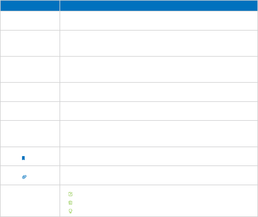
symbols on the web
page
• click to edit the corresponding entry.
• click to delete the corresponding entry.
• click to enable or disable the corresponding entry.


3
Chapter 1 Get to Know About Your Powerline Extender
1. 1. Product Overview
What This Product Does
TP-LINK’s TL-WPA8630P AV1200 Gigabit Passthrough Powerline ac Wi-Fi Extender is
a combined wired/wireless network expansion device. With the help of your home’s
existing electrical circuitry, it can extend your Wi-Fi to wherever you want in your house.
802.11ac - The Next Generation of Wi-Fi
TP-LINK’s TL-WPA8630P comes with the next generation Wi-Fi standard – 802.11ac,
backward compatible with 802.11n and 3 times faster than wireless N speeds. With
higher power efficiency and robust security, 802.11ac is the perfect way to accelerate
a home multimedia network and solve congestion that multiple devices may cause.
1200Mbps Concurrent Dual Band - More Bandwidth, Less Interference
With 866Mbps wireless speeds over the crystal clear 5GHz band and 300Mbps over the
2.4GHz band, TL-WPA8630P offers you the flexibility of two dedicated networks and
ensures amazing wireless performance. Simple tasks such as sending e-mails or web
browsing can be handled by the 2.4GHz band while bandwidth intensive tasks like
online gaming or HD video streaming can be processed by the 5GHz band – all at the
same time.
Extra Power Socket for Additional Devices
The integrated electrical socket can be used like a traditional electrical socket. Simply
plug in your device or extension lead as though it were a normal wall socket. Its built-
in noise filter also reduces some electrical noise that may interfere with powerline
performance.
1. 2. Main Features
• New Generation of Utility to manage the whole powerline network easily and
conveniently.
• Wi-Fi Move to synchronize any changes to Wi-Fi Settings across a secured powerline
network.
• Wi-Fi Clone to copy wireless network name (SSID) and password of your router to the
extender at the press of a button.
• Guest Network to set a separate new wireless network for guests without disclosing
your own wireless network.
• Button control to turn LEDs or Wi-Fi on or off with the press of a button.
• Wi-Fi Schedules to set when your Wi-Fi be on.
4
Chapter 1 Get to Know About Your Powerline Extender
• Multiple Ethernet ports to connect the TVs, game consoles, or PCs to the Internet at
the same time.
• Integrated power socket ensures no power outlet goes to waste.
1. 3. Product Appearance
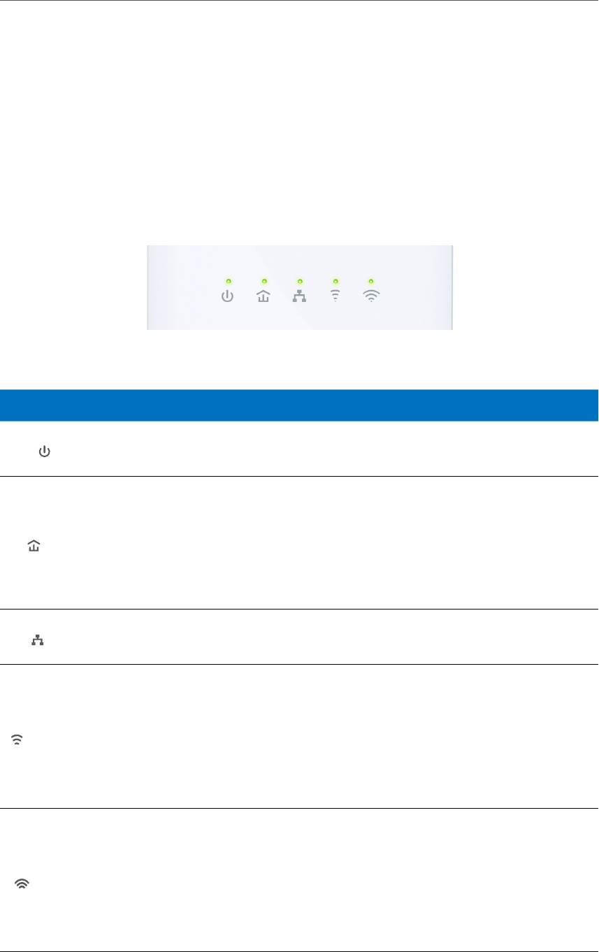
1. 3. 1. LED Legend
LEDs of the extender are located on the front side. They indicate the working status. For
more details, please refer to the following table.
Name Status Indication
Power
On/Off The powerline extender is on or off.
Blinking Pairing is in process.
Powerline
Yellow-
green
The powerline extender is in a location with a good signal
strength.
Red The powerline extender is in a location with a poor signal
strength. We recommend trying another wall socket.
Off The powerline extender is not connected to any powerline
network.
Ethernet
On At least one Ethernet port is connected.
Off No Ethernet port is connected.
2.4GHz Wireless
On 2.4GHz wireless network is enabled.
Off 2.4GHz wireless network is disabled.
Blinking
Slowly: The powerline extender is cloning 2.4GHz wireless
network settings from the main router.
Quickly: The powerline extender is syncing 2.4GHz wireless
network settings.
5GHz Wireless
On 5GHz wireless network is enabled.
Off 5GHz wireless network is disabled.
Blinking
Slowly: The powerline extender is cloning 5GHz wireless
network settings from the main router.
Quickly: The powerline extender is syncing 5GHz wireless
network settings.
5
Chapter 1 Get to Know About Your Powerline Extender
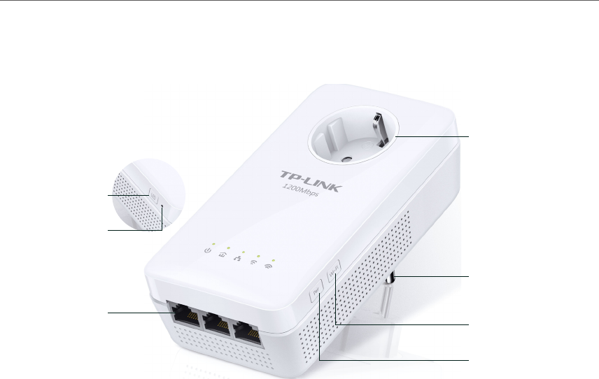
1. 3. 2. Physical Interface
LED Button
Press and hold the LED button for 1 second to turn all LEDs on or off. All LEDs are on by
default. If you don’t feel like being bothered by the LED light at night, press and hold
the button for 1 second to turn all LEDs off. The next morning, just press and hold the
button again to turn them on.
Reset Button
Use a pin to press and hold the Reset button for at least 5 seconds to reset the powerline
extender to factory default settings. All LEDs will turn off and start on again.
Wi-Fi Button
Press and hold the button for 1 second to copy wireless settings from the main router
to the extender. Go to Wi-Fi Clone for more information.
Press and hold the button for at least 5 seconds to turn the wireless function on or off.
The wireless function is on by default. You can turn them off at night and then on in the
morning by pressing the Wi-Fi button.
Pair Button
Press and hold the button for 1 second to join a powerline network. Go to To Set Up a
New Secure Wireless Network for more information.
Press and hold the button for about 8 seconds to leave the existing powerline network.
All LEDs will turn off and start on again.
LED Button
Ethernet Port
Reset Button
Pair Button
Wi-Fi Button
Power Plug
Integrated
Electrical Socket
6
Chapter 1 Get to Know About Your Powerline Extender
Ethernet Port
The extender has three 10/100/1000Mbps Ethernet ports. You can use them to connect
the extender to computers or broadband devices.
Integrated Electrical Socket
Used as a pass-through AC outlet to power other devices. Its built-in noise filter also
reduces some electrical noise that may interfere with powerline performance.
Power Plug
The extender has a Power Plug which can connect to any (100V-240V~, 50/60Hz) power
socket.
Note:
1. The provided integrated electrical socket and power plug may differ from the picture due to different regional
power specifications. Here we take the EU version as an example.
2. Please use the product in upward direction.

8
Chapter 2 Initial Use
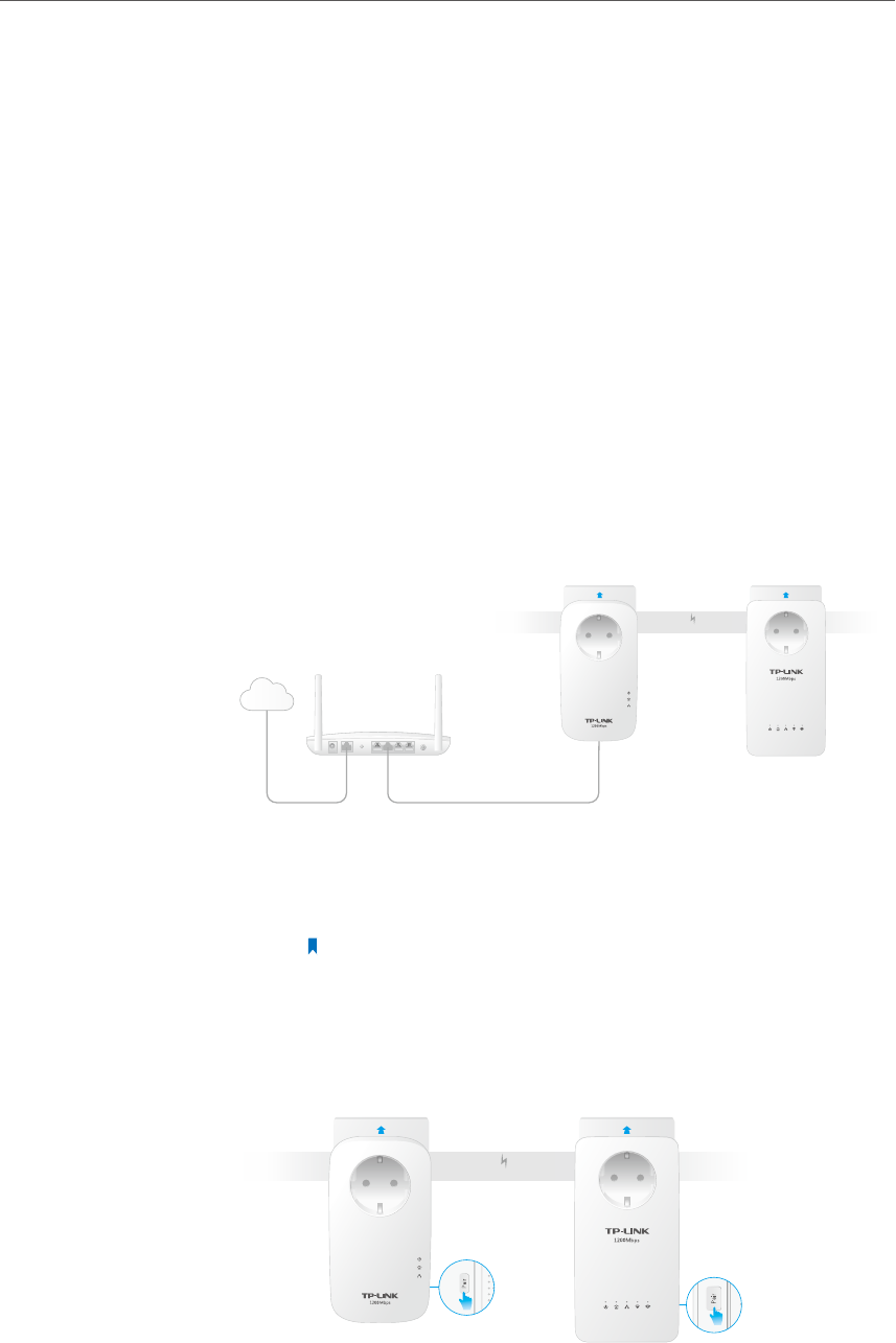
2. 1. To Set Up a New Secure Wireless Network
Use the Powerline Wi-Fi Kit to set up a new secure wireless
network in my house.
For example, I have a wireless router in my house, but the wireless
signal cannot reach every corner. So I bought a Powerline Wi-
Fi Kit to extend the wireless network. The Powerline Wi-Fi Kit
includes a powerline adapter and a powerline extender.
1. Connect the powerline adapter to an available LAN port of
the router.
2. Plug the powerline adapter into a wall socket.
3. Plug the powerline extender into a wall socket near the
adapter.
WAN LAN
Powerline
Internet
Powerline Adapter Powerline Extender
4. Pair the powerline devices.
a . Press the Pair button of the powerline adapter for 1
second. The Power LED starts blinking.
Note: If the Power LED does not blink, press it again.
b . Within two minutes, press the Pair button of the
powerline extender for 1 second. The Power LED starts
blinking. When the Powerline LED stays on, the pairing
process is done!
Powerline
Powerline Adapter Powerline Extender
I want to:
How can I
do that?
9
Chapter 2 Initial Use
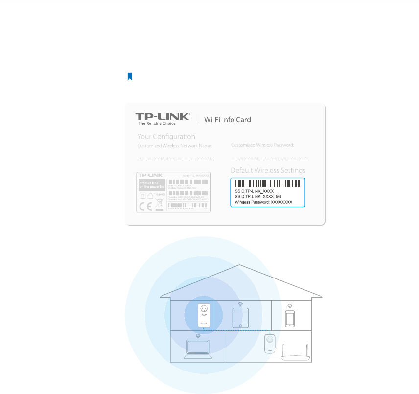
5. Find the Wi-Fi Info Card in the package, and then relocate
the powerline extender to a new location. Connect to the
Wi-Fi using the SSID and password on the card.
Note: A red Powerline LED indicates poor signal strength, we recommend
another location.
Now enjoy the Internet with the SSID and password printed on
the Wi-Fi Info Card!
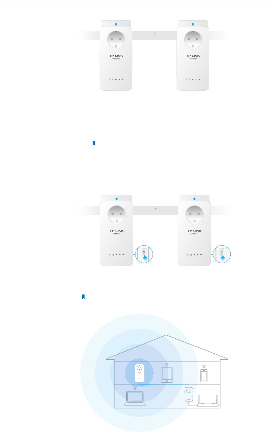
2. 2. To Extend the Existing Wireless Network
Extend the existing wireless network by adding a new powerline
extender into the existing powerline network.
For example, I already set up a wireless network using powerline
devices, but the wireless network is still not big enough to reach
the top floor. So I bought a new powerline extender to extend
the wireless network.
1. Plug the new powerline extender into a wall socket near one
of the existing powerline extender.
Done!
I want to:
How can I
do that?
10
Chapter 2 Initial Use
Powerline
New Powerline ExtenderExisting Powerline Extender
2. Join the new powerline extender into the existing powerline
network by Pairing two powerline devices.
a . Press the Pair button on the existing powerline extender
for 1 second. The Power LED starts blinking.
Note: If the Power LED does not blink, press again.
b . Within two minutes, press the Pair button on the new
powerline extender for 1 second. The Power LED starts
blinking. When the Powerline LED stays on, the pairing
process is done!
Powerline
New Powerline ExtenderExisting Powerline Extender
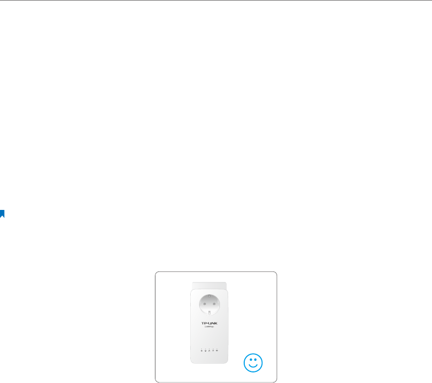
3. Relocate the new powerline extender to where Wi-Fi is
preferred.
Note: A red Powerline LED indicates poor signal strength, we recommend
another location.

11
Chapter 2 Initial Use
Now enjoy the Internet! The SSID and password are the same as
that of your old wireless network!
If you still don’t have wireless signals near the new extender, it
is possibly you haven’t paired your old powerline devices. We
recommend you follow the steps below to pair them. Please
note that Pair can only be used on two devices at a time.
1. Press the Pair button on the old powerline extender for 1
second. Then its Power LED starts blinking.
Note: If the Power LED does not blink, press again.
2. Press the Pair button on the old powerline adapter for
1 second. Then its Power LED starts blinking. When the
Powerline LED stays on, it’s done!
3. The SSID and password used for Internet connection are the
ones printed on the back of your old powerline extender.
Done!
Q & A:

Chapter 3
Conguring via Web
Management Interface
The powerline extender has a management interface to configure all settings. The
management interface can be opened on any device that has a web browser, such as
Internet Explorer, Chrome or Firefox. This chapter is going to give detailed information
on what functions the powerline extender has and how to configure them.
This chapter contains the following sections:
Management Interface
Manage Powerline Network
Wi-Fi Move
Wi-Fi Clone
Wireless Network
LED Schedules
Schedule Your Wireless Function
Parental Controls
Guest Network
MAC Filter
Administration
13
Chapter 3 Conguring via Web Management Interface
3. 1. Management Interface
3. 1. 1. Login
There are two methods to log into the management interface, each with a different
hardware connection type.
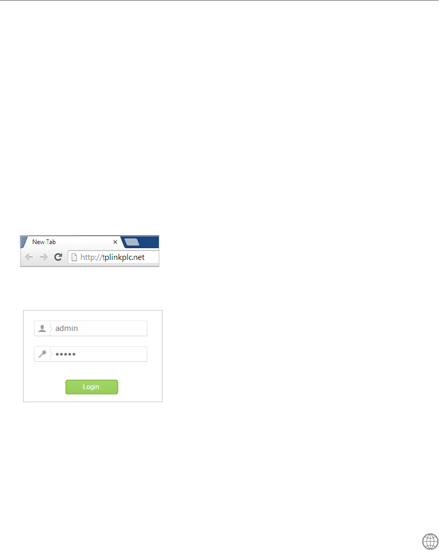
Method 1: Wireless Login
Follow the steps below:
1. Connect your device to the powerline extender wirelessly.
2. Launch a web browser and type in http://tplinkplc.net to open the management
interface.
3. Enter admin (the default username and password) for both username and password.
We recommend you change them immediately after your first login.
4. Click Login.
Method 2: Wired Login
Follow the steps below:
1. Connect your computer to the powerline extender with the provided Ethernet cable.
2. Obtain and install the tpPLC utility (for Windows) from the product support page at
http://www.tp-link.com.
3. Open the utility, move your mouse over your powerline extender, and click the
icon that appears beside it.
4. Enter admin for both username and password.
5. Click Login.
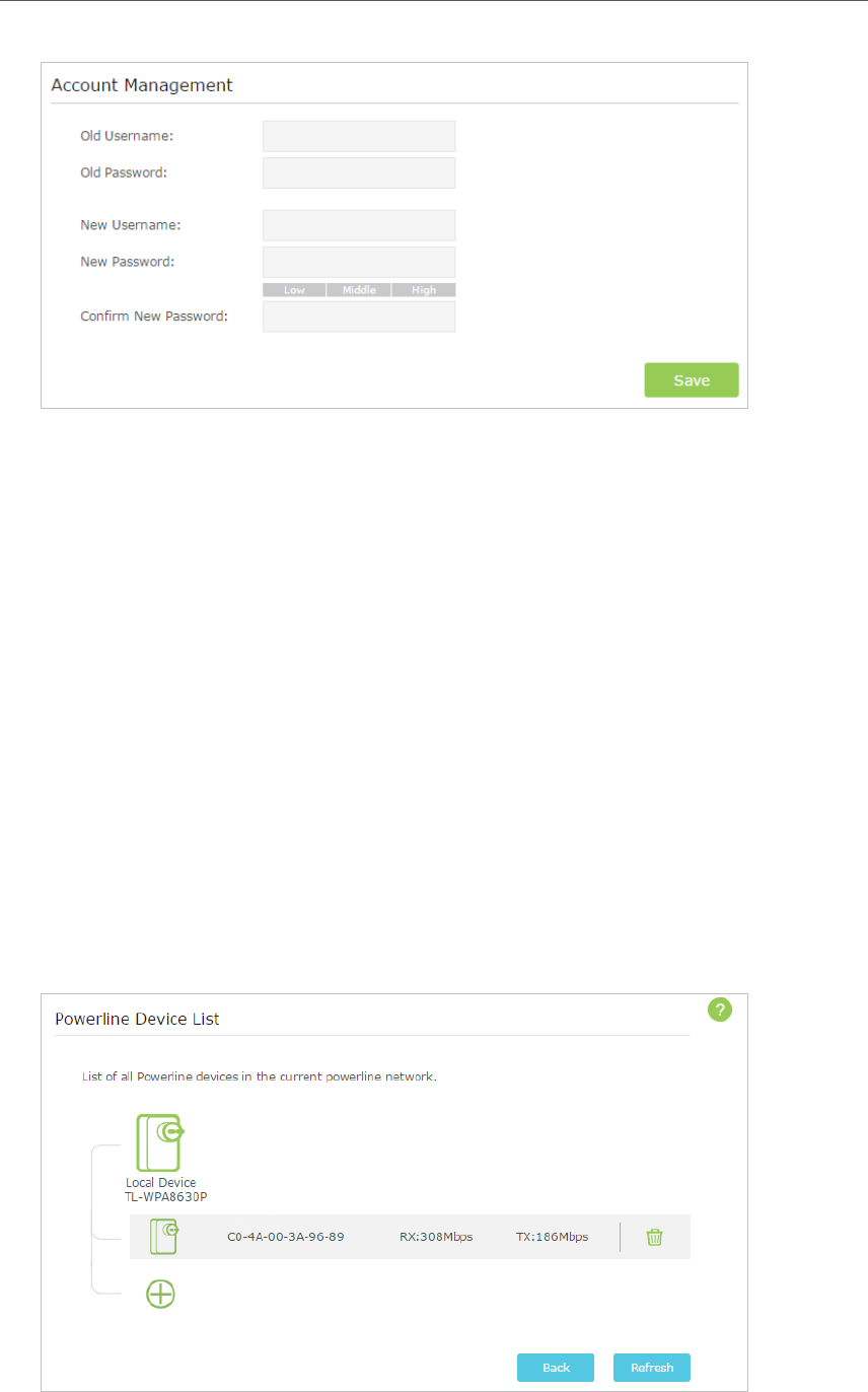
3. 1. 2. Change the Login Account
We strongly recommend you change the login account immediately after the first login.
Follow the steps below to change the account.
1. Go to System Tools > Administration.
14
Chapter 3 Conguring via Web Management Interface
2. Follow instructions on the page to set a new username and password. A strong
password should be at least 8 or more characters in length, combining uppercase
and lowercase letters, numbers and punctuations.
3. Click Save to make the settings effective.
3. 2. Manage Powerline Network
A powerline network is formed of powerline devices, including adapters and extenders.
Powerline devices in the same powerline network share the same powerline network
name.
3. 2. 1. Add a New Device to the Powerline Network
1. Connect to the powerline extender wirelessly. Visit http://tplinkplc.net, and log in
with the password you set for the extender.
2. Go to the Status page. Click the Powerline Network icon to see the Powerline Device
List.
15
Chapter 3 Conguring via Web Management Interface
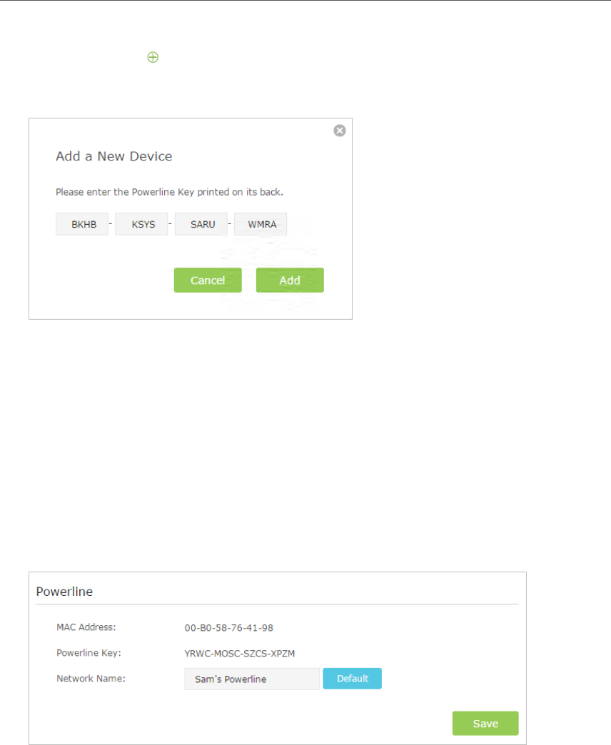
3. Click the add icon and enter the Powerline Key of the device you want to add. The
Powerline Key contains 16 capital letters, formed like XXXX-XXXX-XXXX-XXXX. It is
printed on the back of the powerline device.
4. Click Add to add the device.
3. 2. 2. Change Powerline Network Name
You can change the extender’s powerline network name to add it to or remove it from
a powerline network.
Follow the steps below to change the name.
1. Connect to the powerline extender wirelessly. Visit http://tplinkplc.net, and log in
with the password you set for the extender.
2. Go to Device Settings > Powerline.
3. Change the Network name. You can also click Default to use the default network
name, e.g. HomePlugAV. However, if the default name is used, the Wi-Fi Move
function will be automatically disabled.
4. Click Save to make the settings effective.
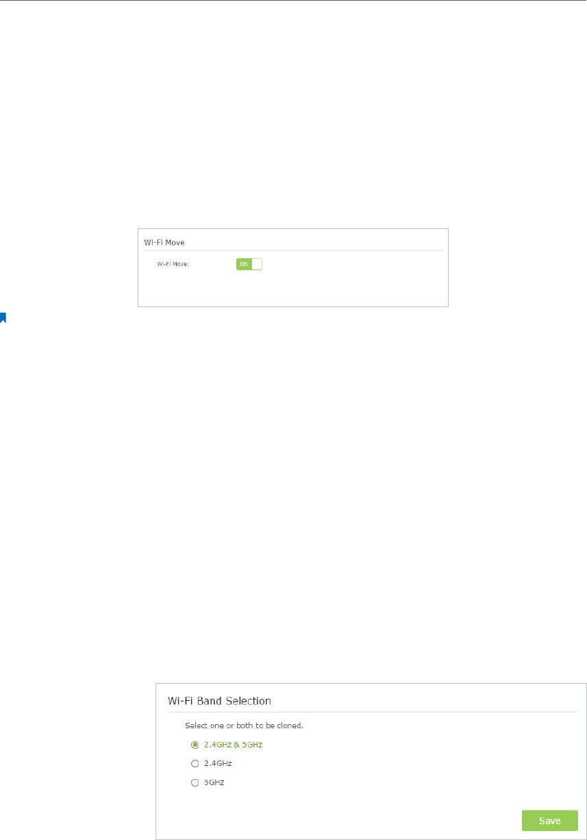
3. 3. Wi-Fi Move
Wi-Fi Move feature is enabled by default. With the feature enabled, any changes made
to the Wi-Fi settings of one powerline extender will automatically synchronize to other
16
Chapter 3 Conguring via Web Management Interface
powerline extenders on the same powerline network whose Wi-Fi Move feature is also
enabled.
Follow the Steps below to enable Wi-Fi Move feature:
1. Connect to the powerline extender wirelessly. Visit http://tplinkplc.net, and log in
with the password you set for the extender.
2. Go to Wireless > Wi-Fi Move.
3. Toggle On to enable the feature.
Note:
When Wi-Fi Move is enabled, the following features will be synced: Wireless SSID & Password; Wireless Security;
Wireless Mode; Wireless Radio Status; Wi-Fi Schedules; LED Schedules; Wi-Fi Clone Settings; MAC Filter Settings;
Parental Controls, Guest Network.
3. 4. Wi-Fi Clone
Copy wireless settings from my router to my extender, so I can
use the same SSID and password to access the Internet in my
house.
1. Connect to the powerline extender wirelessly. Visit http://
tplinkplc.net, and log in with the password you set for the
extender.
2. Go to Wireless > Wi-Fi Clone.
3. Select a Wi-Fi band or both to be cloned. 2.4GHz & 5GHz is
selected by default.
4. Before cloning, make sure your router supports the same
band as your extender. If you do not know how to check this,
go to your router’s User Guide for more information.
5. Plug your extender near your router.
I want to:
How can I
do that?
17
Chapter 3 Conguring via Web Management Interface
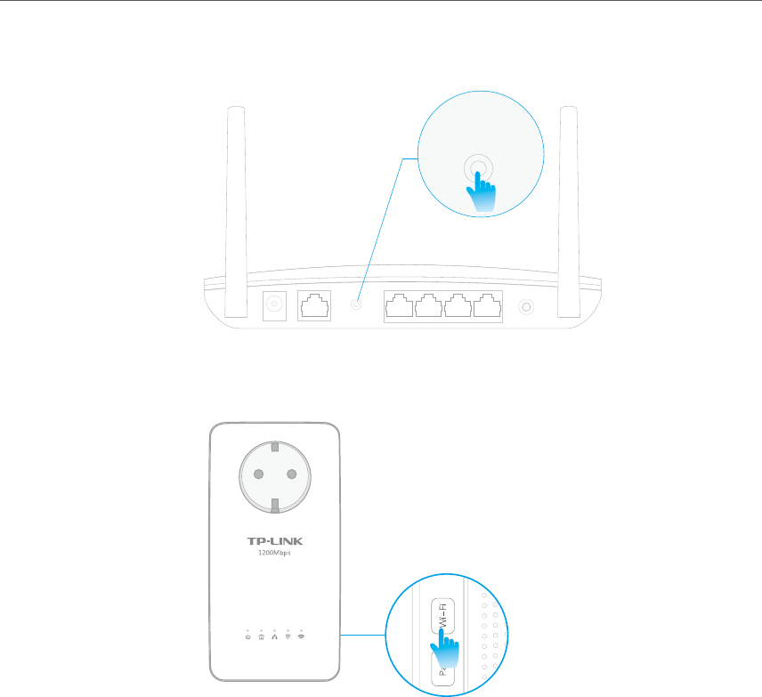
6. Press the WPS button on your router.
WPS
WPS
WAN
7. Within two minutes, press the Wi-Fi button on the side panel
of the extender.
When the corresponding Wi-Fi LED blinks quickly for 3 seconds
and then stays on. It’s done!
3. 5. Wireless Network
3. 5. 1. Customize Wireless Settings
The powerline extender’s wireless network name (SSID) and password, and security
option are preset in the factory. The preset SSID and password can be found on the
product label and Info Card. You can customize the wireless settings according to your
needs.
Connect to the powerline extender wirelessly. Visit http://tplinkplc.net, and log in with
the password you set for the extender.
Go to Wireless > Settings page.
Done!
18
Chapter 3 Conguring via Web Management Interface
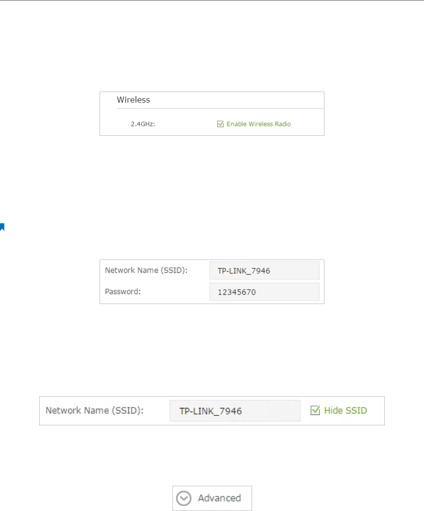
To enable or disable the wireless function:
Enable the Wireless Radio of 2.4GHz or 5GHz. Uncheck the box to disable wireless
function. If disabled, all wireless settings of the corresponding band will be ineffective.
To change the wireless network name (SSID) and wireless password:
The default SSID is TP-LINK_XXXX, and the default password is 12345670. You can
change the default ones by directly entering new ones in the field. SSID is up to 32
characters, and the value in both SSID and password is case-sensitive.
Note:
Remember to write down the new SSID and password, for you may be disconnected when new settings are effective.
To hide SSID:
Select Hide SSID, and your SSID will not broadcast. It won’t display when you scan for
local wireless network list on your wireless device and you need to manually join the
network.
To have more advanced settings
Click Advanced below Password to have more advanced settings.
19
Chapter 3 Conguring via Web Management Interface
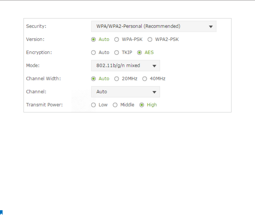
Security: Select an option from the Security drop-down list. The extender provides
four options, None, WPA/WPA2 Personal (Recommended), WPA/WPA2 Enterprise, WEP.
WPA2 uses the newest standard and the security level is the highest. We recommend
you don’t change the default settings unless necessary.
Mode: Select the desired mode.
• 802.11n only: Select only if all of your wireless clients are 802.11n devices.
• 802.11g/n mixed: Select if you are using both 802.11g and 802.11n wireless clients.
• 802.11b/g/n mixed: Select if you are using a mix of 802.11b, 11g, and 11n wireless
clients.
Note: When 802.11n only mode is selected, only 802.11n wireless clients can connect to the extender. It is strongly
recommended that you select 802.11b/g/n mixed, and all of 802.11b, 802.11g, and 802.11n wireless clients can
connect to the extender.
• 802.11ac only (5GHz): Select only if all of your wireless clients are 802.11ac devices.
• 802.11ac/n mixed (5Ghz): Select if you are using both 802.11ac and 802.11n wireless
clients.
• 802.11a/n/ac mixed (5Ghz): Select if you are using a mix of 802.11ac, 802.11n and
802.11ac wireless clients. It is strongly recommended that you select 11a/n/ac mixed.
Channel Width: Select the channel width from the drop-down list. The default setting is
automatic, which can adjust the channel width for your clients automatically.
Channel: Select the channel you want to use from the drop-down list. This field
determines which operating frequency will be used. It is not necessary to change the
wireless channel unless you notice interference problems with another nearby access
point.
RADIUS Server IP: Enter the IP address of the RADIUS Server.
RADIUS Port: Enter the port used by RADIUS service.
Transmit Power: Select the level of transmit power. We recommend you choose high to
have the best signal strength.
20
Chapter 3 Conguring via Web Management Interface
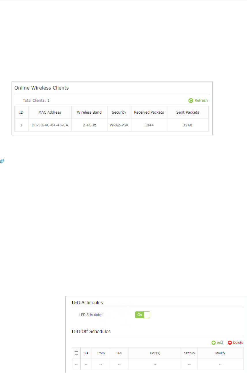
3. 5. 2. Wireless Clients
Follow the steps below to view detailed information of all wireless clients connected to
the extender.
1. Connect to the powerline extender wirelessly. Visit http://tplinkplc.net, and log in
with the password you set for the extender.
2. Go to Wireless > Clients page.
3. Now you can view the detailed information, including MAC address, connected
wireless band, security option as well as the packets transmitted.
Tips: You can also see the wireless details by clicking the wireless clients icon on Status> Wireless Clients.
3. 6. LED Schedules
Automatically turn off LEDs at times when I do not want light in
my room.
For example, I want to turn LEDs off everyday from 00:00am to
7:00am.
1. Connect to the powerline extender wirelessly. Visit http://
tplinkplc.net and log in with the username and password you
set.
2. Go to Device Settings > LED Schedules.
3. Toggle On to enable the LED Scheduler.
4. Click Add to add an entry.
I want to:
How can I
do that?
21
Chapter 3 Conguring via Web Management Interface
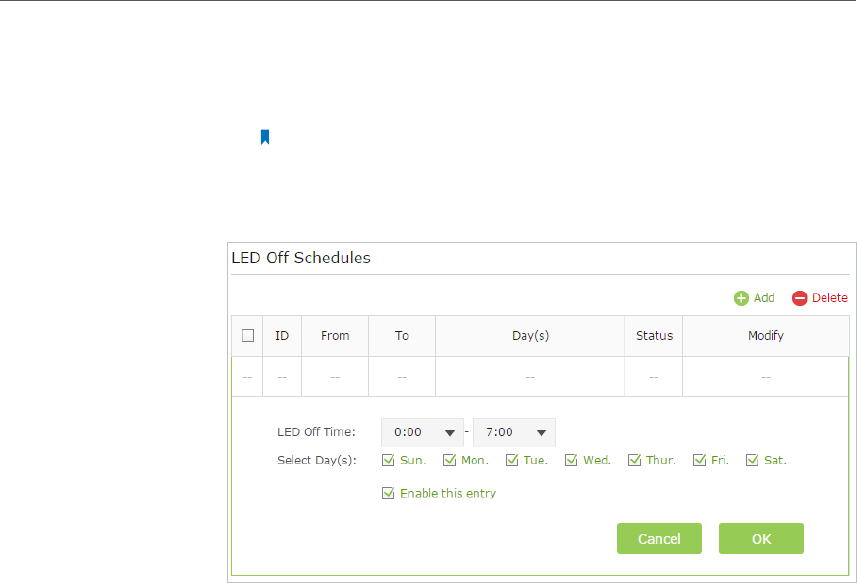
5. Choose LED Off Time from 00:00 to 7:00, and then check all
boxes from Sunday to Saturday.
Note: Please make sure that the Time Settings are correct
before using this function.
6. Click Enable this entry to make it effective.
7. Click OK to save the settings.
Now your LEDs will be turned off automatically at 00:00 and
turned on at 7:00am the next morning.
3. 7. Schedule Your Wireless Function
Automatically turn off my wireless network (both 2.4GHz and
5GHz) at times when I do not need the wireless connection.
For example, I want to turn them off from 00:00am to 7:00am.
Yet if I have my wireless devices connected to the extender at
that time, I want the wireless on till all devices are disconnected
from the Internet.
1. Connect to the powerline extender wirelessly. Visit http://
tplinkplc.net and log in with the username and password you
set.
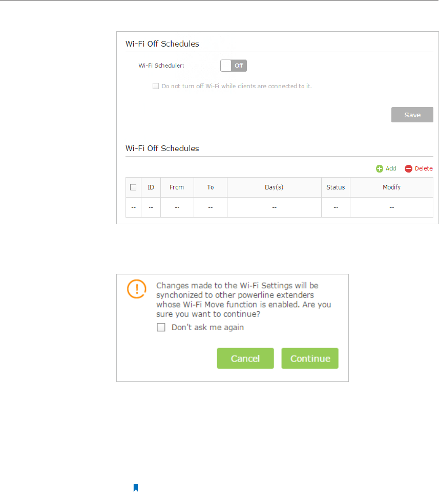
2. Go to Wireless > Wi-Fi Schedules.
Done!
I want to:
How can I
do that?
22
Chapter 3 Conguring via Web Management Interface
3. Toggle On to enable the Wi-Fi Scheduler. If you are prompted
like the following picture, click Continue.
4. Check the box of Do not turn off Wi-Fi while clients are
connected to it.
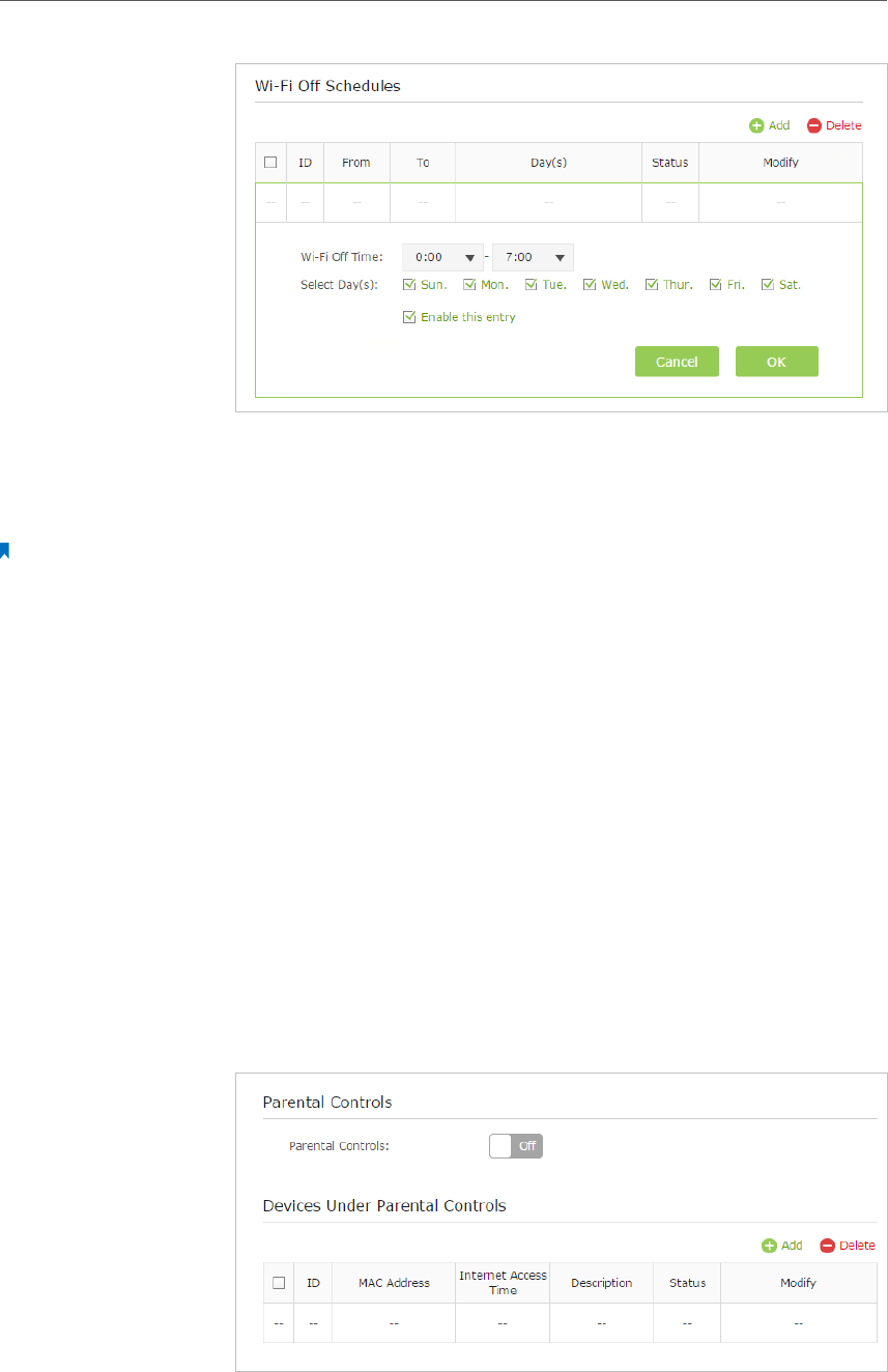
5. Click Add to add an entry.
6. Choose 00:00 and 7:00 from the drop-down list. Check all
boxes from Sunday to Saturday.
Note: Please make sure that the Time Settings are correct before using this
function.
7. Click Enable this entry to make it effective.
23
Chapter 3 Conguring via Web Management Interface
8. Click OK to save the settings.
Now your Wi-Fi will be automatically turned off at 00:00 and
turned on at 7:00am the next morning.
Note:
The wireless LED (2.4GHz , 5GHz ) will turn off if the corresponding wireless network is disabled.
3. 8. Parental Controls
Control when my children’s wireless devices can access the
Internet.
For example, I want to allow my children’s wireless devices to
access only from 18:00 (6PM) to 22:00 (10PM) on weekdays and
not other times.
1. Connect to the powerline extender wirelessly. Visit http://
tplinkplc.net, and log in with the password you set for the
extender.
2. Go to Parental Controls.
3. Toggle On to enable Parental Controls.
Done!
I want to:
How can I
do that?
24
Chapter 3 Conguring via Web Management Interface
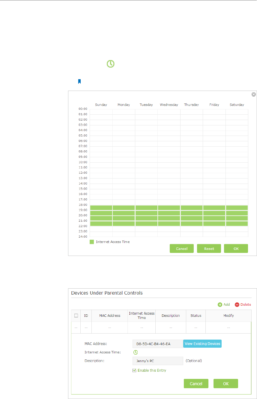
4. Click Add.
5. Click View Existing Devices, and select the device to be
controlled. Or, enter the Device Name and MAC Address
manually.
6. Click the icon to set the Internet Access Time. Drag the
cursor over the appropriate cell(s) and click OK.
Note: Please make sure that the Time is correct before using this function.
7. Enter a Description for the entry.
8. Click Enable this entry to make it effective.
9. Click OK to save the settings.
25
Chapter 3 Conguring via Web Management Interface
Now you can control when your children can access the Internet
according to your needs.
3. 9. Guest Network
Create a separate network for my guests, providing Internet
access for them while at the same time limit the network
authorities for guests to ensure network security and privacy.
1. Connect to the powerline extender wirelessly. Visit http://
tplinkplc.net, and log in with the password you set for the
extender.
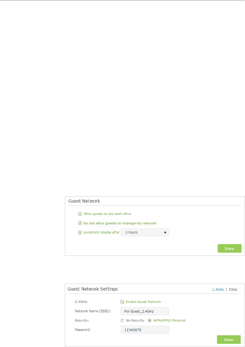
2. Go to Guest Network.
3. Check the box of relative entry to limit network authorities.
If you have problems understanding these items, click the
question mark on the upper right corner to have more
information.
4. Click Save to make the settings effective.
5. Click 2.4GHz or 5GHz to choose a wireless band, and
configure the following settings.
To enable or disable the wireless function:
Enable the Wireless Radio of 2.4GHz or 5GHz. Uncheck the box
to disable wireless function. If disabled, all wireless settings of
the corresponding band will be ineffective.
Done!
I want to:
How can I
do that?

26
Chapter 3 Conguring via Web Management Interface
To change the wireless network name (SSID) and wireless
password:
The default SSID is TP-LINK_GUEST_XXXX, and the default
password is 12345670. You can change the default ones by
directly entering new ones in the field. SSID is up to 32 characters,
and the value in both SSID and password is case-sensitive.
Note:
Remember to write down the new SSID and password, for you will be disconnected
when new settings are effective.
Now you can tell your guests to connect to the guest network
you created.
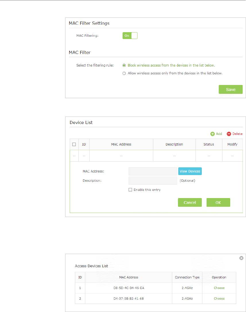
3. 10. MAC Filter
This function exploits the uniqueness of the MAC (Medium Access Control) address,
a unique 12-digit hexadecimal address (for example, D8:5D:4C:B4:46:EA) of every
network device, to determine if the device can or cannot access your wireless network.
Prevent unauthorized users from accessing my wireless network
by utilizing the network device’s MAC address and IP address.
For example, I have a computer that is connected to my wireless
network. Now, an unknown device (an intruder) is also using my
wireless network, which affects my Internet speed. I would like
to control my wireless network with the following capabilities:
• My computer is always allowed to access the wireless network.
• The unknown device is not allowed to access the wireless
network.
• I don’t have to keep changing my wireless password as often.
1. Connect to the powerline extender wirelessly. Visit http://
tplinkplc.net, and log in with the password you set for the
extender.
2. Go to Wireless> MAC Filter.
3. Toggle On to enable MAC Filter.
4. Select either of the filtering rules and click Save. Here we
select Block wireless access from the devices listed below
and then click Save.
Done!
I want to:
How can I
do that?
27
Chapter 3 Conguring via Web Management Interface
5. Click Add under Device List to add devices to the list.
6. Click View Devices to see how many devices are now
connected to the network. Click Choose to choose a device.
You can also enter in the MAC address manually.
7. Give a description of the entry here. (Optional)
8. Click Enable this entry to make this entry effective.
9. Click Ok to save the settings.
Now MAC Filtering is implemented to protect your wireless
network.
Done!
28
Chapter 3 Conguring via Web Management Interface
3. 11. Administration
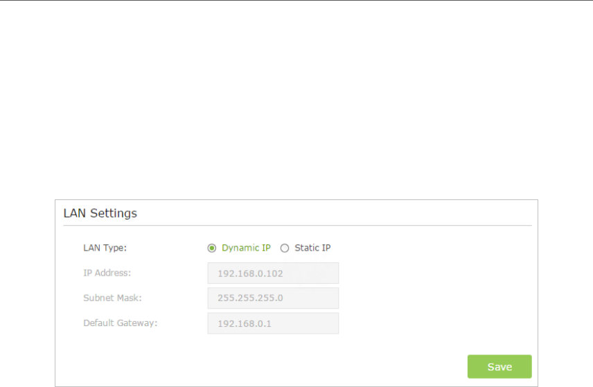
3. 11. 1. LAN IP Address
Follow the steps below to configure LAN settings of the extender.
Go to Device Settings > LAN Settings.
LAN Type: Select Dynamic IP to have your extender automatically obtain IP Address
from the main router. Select Static IP to manually configure the LAN parameters.
IP Address: The IP address of the powerline extender.
Subnet Mask: The subnet mask associated with IP address.
Default Gateway: The IP address of the gateway device.
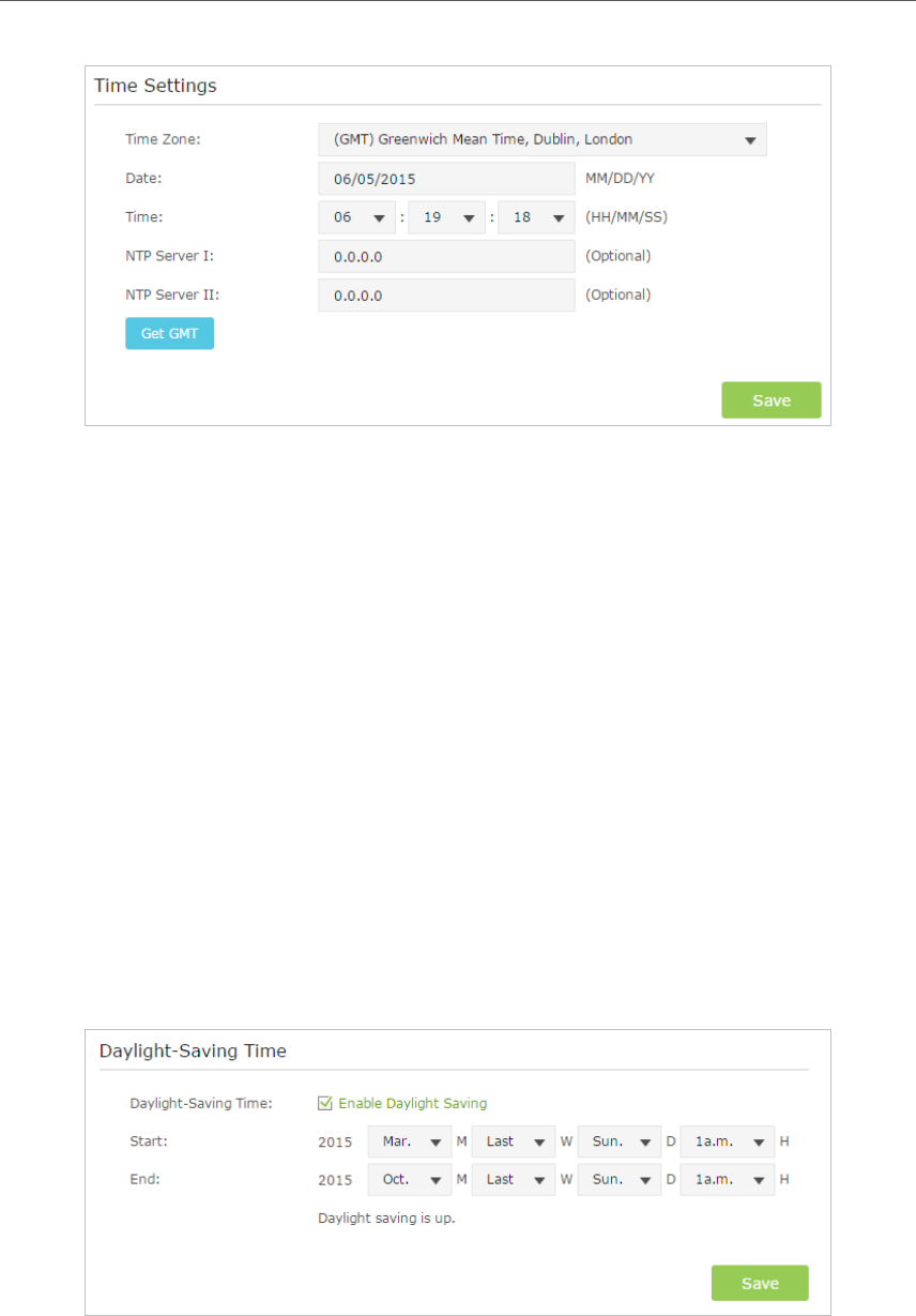
3. 11. 2. Set Up System Time
System time is the time displayed while the extender is running. The system time you
configure here will be used for other time-based functions like Parental Controls, Wi-Fi
Schedules. You can manually set how to get the system time.
Connect to the powerline extender wirelessly. Visit http://tplinkplc.net, and log in with
the username and password you set for the extender.
Go to System Tools > Time Settings page.
29
Chapter 3 Conguring via Web Management Interface
To automatically synchronize the time:
1. Select your local Time Zone from the drop-down menu.
2. In the NTP Server I field, enter the IP address or domain name of your desired NTP
Server. (Optional)
3. In the NTP Server II field, enter the IP address or domain name of the second NTP
Server. (Optional)
4. Click Get GMT.
To manually set the date and time:
1. In the Time Settings field, select your local Time Zone.
2. Enter the current Date.
3. Set the current Time (In 24-hour clock format, e.g. 16:00:00 is 04:00PM).
4. Click Save.
To set up Daylight Saving time:
1. Select Enable Daylight Saving.
2. Select the correct Start date and time when daylight saving time starts at your local
time zone.
30
Chapter 3 Conguring via Web Management Interface
3. Select the correct End date and time when daylight saving time ends at your local
time zone.
4. Click Save.
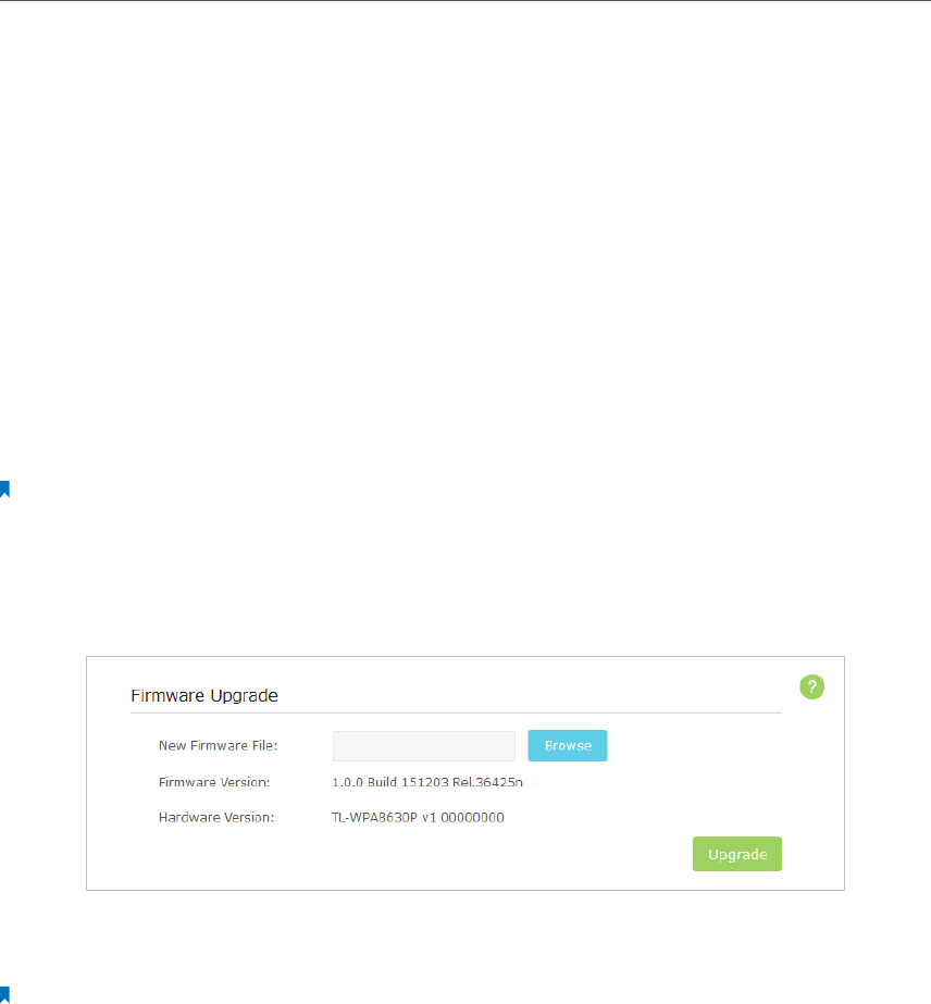
3. 11. 3. Upgrade the Firmware
TP-LINK is dedicated to improving and richening the product features, giving you a
better network experience. We will release the latest firmware at TP-LINK official
website, you can download the latest firmware file from our website: www.tp-link.com
and upgrade the firmware to the latest version.
1. Download the latest firmware file for the extender from our website: www.tp-link.
com.
Note: The upgraded firmware version must correspond to the hardware.
2. Connect to the powerline extender wirelessly. Visit http://tplinkplc.net, and log in
with the username and password you set for the extender.
3. Go to System Tools > Firmware Upgrade page.
4. Click Browse to locate the downloaded new firmware file, and click Upgrade.
5. Wait a few minutes for the upgrading and rebooting.
Note:
1. Before upgrading the firmware, it’s better to back up your current settings.
2. During the upgrading process, do not turn off or reset the extender.
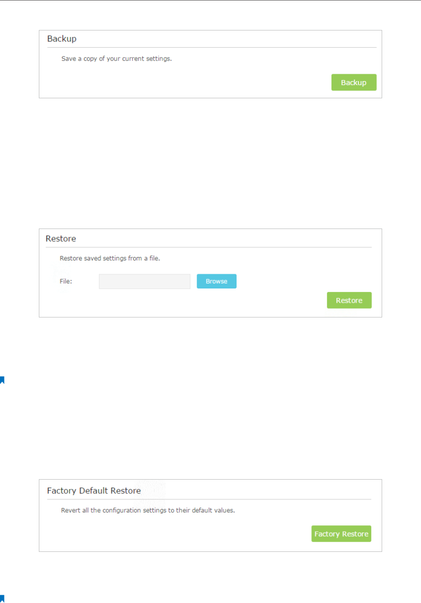
3. 11. 4. Backup and Restore Configuration Settings
The configuration settings are stored as a configuration file in the extender. You can
back up the configuration file to your computer for future use and restore the extender
to a previous settings from the backup file when needed. Moreover, if needed you can
erase the current settings and reset the extender to the default factory settings.
To backup configuration settings:
1. Connect to the powerline extender wirelessly. Visit http://tplinkplc.net, and log in
with the username and password you set for the extender.
2. Go to System Tools > Backup & Restore page.
31
Chapter 3 Conguring via Web Management Interface
3. Click Backup to save a copy of the current settings to your local computer. A config.
bin file will be stored to your computer.
To restore configuration settings:
1. Connect to the powerline extender wirelessly. Visit http://tplinkplc.net, and log in
with the username and password you set for the extender.
2. Go to System Tools > Backup & Restore page.
3. Click Browse to locate the backup configuration file stored on your computer, and
click Restore. The configuration file is config.bin.
4. Wait a few minutes for the restoring and rebooting.
Note: During the restoring process, do not turn off or reset the extender.
To reset the extender to factory default settings:
1. Connect to the powerline extender wirelessly. Visit http://tplinkplc.net, and log in
with the username and password you set for the extender.
2. Go to System Tools > Backup & Restore page.
3. Click Factory Restore to reset the extender.
4. Wait a few minutes for the resetting and rebooting.
Note:
1. During the resetting process, do not turn off the extender.
2. We strongly recommend you back up the current configuration settings before resetting the extender.
32
Chapter 3 Conguring via Web Management Interface
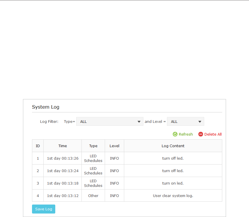
3. 11. 5. System Log
When the extender does not work properly, you can save the system log and send it to
the technical support for troubleshooting.
Follow the steps below to save the system log:
1. Connect to the powerline extender wirelessly. Visit http://tplinkplc.net, and log in
with the username and password you set for the extender.
2. Go to System Tools > System Log.
3. Choose the type and level of the system log according to your need.
4. Click Save Log to save the system log to local.

Appendix A: Specications
Hardware
Transmission Speeds Powerline: up to 1200 Mbps
Ethernet: 10/100/1000 Mbps
Standards and
Protocols
HomePlug AV, IEEE 1901,IEEE 802.3, IEEE 802.3u, IEEE 802.11b/g/n 2.4GHz,
IEEE 802.11a/ac 5GHz
Interface 3 * Built-in Ethernet Port
Plug Type EU, UK, US
Access Methods CSMA/CA channel-access schemes
IGMP IGMP v1/v2/v3
Power Consumption Maximum: 10.8 W (230V/50Hz)
Standby: 5 W (230V/50Hz)
Range 300 meters in house
Compatibility Compatible with all HomePlug AV & HomePlug AV2 standard Powerline
adapters/extenders
Software
Modulation
Technology OFDM
Security 128-bit AES Encryption
Quality of Service
(QoS)
ToS
Supports up to 4-level type QoS
Supports up to 8-level VLAN priority field
Other
Certification CE, RoHS
System
Requirements Windows 10/8.1/8/7/Vista/XP, Mac OS, Linux2
Environment
Operating Temperature: 0°C~40°C (32°F~104°F)
Storage Temperature: -20°C~70°C (-4°F ~158°F)
Operating Humidity: 10%~90% non-condensing
Storage Humidity: 5%~95% non-condensing

34
COPYRIGHT & TRADEMARKS
Specifications are subject to change without notice. is a registered trademark
of TP-LINK TECHNOLOGIES CO., LTD. Other brands and product names are trademarks
or registered trademarks of their respective holders.
No part of the specifications may be reproduced in any form or by any means or
used to make any derivative such as translation, transformation, or adaptation
without permission from TP-LINK TECHNOLOGIES CO., LTD. Copyright © 2016 TP-LINK
TECHNOLOGIES CO., LTD. All rights reserved.

35
FCC STATEMENT
This equipment has been tested and found to comply with the limits for a Class B
digital device, pursuant to part 15 of the FCC Rules. These limits are designed to provide
reasonable protection against harmful interference in a residential installation. This
equipment generates, uses and can radiate radio frequency energy and, if not installed
and used in accordance with the instructions, may cause harmful interference to radio
communications. However, there is no guarantee that interference will not occur in a
particular installation. If this equipment does cause harmful interference to radio or
television reception, which can be determined by turning the equipment off and on,
the user is encouraged to try to correct the interference by one or more of the following
measures:
• Reorient or relocate the receiving antenna.
• Increase the separation between the equipment and receiver.
• Connect the equipment into an outlet on a circuit different from that to which
the receiver is connected.
• Consult the dealer or an experienced radio/ TV technician for help.
This device complies with part 15 of the FCC Rules. Operation is subject to the following
two conditions:
1 ) This device may not cause harmful interference.
2 ) This device must accept any interference received, including interference that
may cause undesired operation.
Any changes or modifications not expressly approved by the party responsible for
compliance could void the user’s authority to operate the equipment.
Note: The manufacturer is not responsible for any radio or TV interference caused by
unauthorized modifications to this equipment. Such modifications could void the
user’s authority to operate the equipment.
FCC RF Radiation Exposure Statement
This equipment complies with FCC RF radiation exposure limits set forth for an
uncontrolled environment. This device and its antenna must not be co-located or
operating in conjunction with any other antenna or transmitter.
“To comply with FCC RF exposure compliance requirements, this grant is applicable to
only Mobile Configurations. The antennas used for this transmitter must be installed to
provide a separation distance of at least 20 cm from all persons and must not be co-
located or operating in conjunction with any other antenna or transmitter.”
This device is restricted in indoor environment only.

36
CE Mark Warning
This is a class B product. In a domestic environment, this product may cause radio
interference, in which case the user may be required to take adequate measures.
RF Exposure Information
This device meets the EU requirements (1999/519/EC) on the limitation of exposure of
the general public to electromagnetic fields by way of health protection.
The device complies with RF specifications when the device used at 20 cm from your
body.
National Restrictions
This device is intended for home and office use in all EU countries (and other countries
following the EU directive 1999/5/EC) without any limitation except for the countries
mentioned below:
Country Restriction Reason/remark
Belarus Not implemented
Norway Implemented This subsection does not apply for the geographical area within a radius of
20 km from the centre of Ny-Ålesund on Svalbard.
Italy Implemented The public use is subject to general authorisation by the respective service
provider.
Russian
Federation
Limited
implementation
1. SRD with FHSS modulation
1.1. Maximum 2.5 mW e.i.r.p.
1.2. Maximum 100 mW e.i.r.p. Permitted for use SRD for outdoor applications
without restriction on installation height only for purposes of gathering
telemetry information for automated monitoring and resources accounting
systems. Permitted to use SRD for other purposes for outdoor applications
only when the installation height is not exceeding 10 m above the ground
surface.
1.3.Maximum 100 mW e.i.r.p. Indoor applications.
2. SRD with DSSS and other than FHSS wideband modulation
2.1. Maximum mean e.i.r.p. density is 2 mW/MHz. Maximum 100 mW e.i.r.p.
2.2. Maximum mean e.i.r.p. density is 20 mW/MHz. Maximum 100 mW e.i.r.p.
It is permitted to use SRD for outdoor applications only for purposes of
gathering telemetry information for automated monitoring and resources
accounting systems or security systems.
2.3. Maximum mean e.i.r.p. density is 10 mW/MHz. Maximum 100 mW e.i.r.p.
Indoor applications.
Ukraine Limited
implementation e.i.r.p. ≤100 mW with built-in antenna with amplification factor up to 6 dBi.
ATTENTION: Due to EU law, the country settings must be identical to the country where
the device is operating (important due to non-harmonised frequencies in the EU).
Restricted to indoor use.
37
Canadian Compliance Statement
This device complies with Industry Canada license-exempt RSSs. Operation is subject
to the following two conditions:
1. This device may not cause interference, and
2. This device must accept any interference, including interference that may cause
undesired operation of the device.
Le présent appareil est conforme aux CNR d’Industrie Canada applicables aux appareils
radio exempts de licence. L’exploitation est autorisée aux deux conditions suivantes :
1. l’appareil ne doit pas produire de brouillage;
2. l’utilisateur de l’appareil doit accepter tout brouillage radioélectrique subi, meme si
le brouillage est susceptible d’en compromettre le fonctionnement.
Caution:
1. The device for operation in the band 5150–5250 MHz is only for indoor use to reduce
the potential for harmful interference to co-channel mobile satellite systems;
2. For devices with detachable antenna(s), the maximum antenna gain permitted for
devices in the band 5725-5850 MHz shall be such that the equipment still complies
with the e.i.r.p. limits specified for point-to-point and non-point-to-point operation
as appropriate; and
The high-power radars are allocated as primary users (i.e. priority users) of the bands
5250-5350 MHz and 5650-5850 MHz and that these radars could cause interference
and/or damage to LE-LAN devices.
Avertissement:
1. Le dispositif fonctionnant dans la bande 5150-5250 MHz est réservé uniquement
pour une utilisation à l’intérieur afin de réduire les risques de brouillage préjudiciable
aux systèmes de satellites mobiles utilisant les mêmes canaux;
2. Le gain maximal d’antenne permis pour les dispositifs avec antenne(s) amovible(s)
utilisant la bande 5725-5850 MHz doit se conformer à la limitation P.I.R.E spécifiée
pour l’exploitation point à point et non point à point, selon le cas.
En outre, les utilisateurs devraient aussi être avisés que les utilisateurs de radars de
haute puissance sont désignés utilisateurs principaux (c.-à-d., qu’ils ont la priorité) pour
les bandes 5250-5350 MHz et 5650-5850 MHz et que ces radars pourraient causer du
brouillage et/ou des dommages aux dispositifs LAN-EL.
Radiation Exposure Statement:
This equipment complies with IC radiation exposure limits set forth for an uncontrolled
environment. This equipment should be installed and operated with minimum distance
20cm between the radiator & your body.

38
Déclaration d’exposition aux radiations:
Cet équipement est conforme aux limites d’exposition aux rayonnements IC établies
pour un environnement non contrôlé. Cet équipement doit être installé et utilisé avec
un minimum de 20 cm de distance entre la source de rayonnement et votre corps.
Industry Canada Statement
CAN ICES-3 (B)/NMB-3(B)
Korea Warning Statements:
당해 무선설비는 운용중 전파혼신 가능성이 있음.
NCC Notice & BSMI Notice:
注意!
依據 低功率電波輻射性電機管理辦法
第十二條 經型式認證合格之低功率射頻電機,非經許可,公司、商號或使用者均
不得擅自變更頻率、加大功率或變更原設計之特性或功能。
第十四條 低功率射頻電機之使用不得影響飛航安全及干擾合法通行;經發現有干
擾現象時,應立即停用,並改善至無干擾時方得繼續使用。前項合法通信,指依
電信規定作業之無線電信。低功率射頻電機需忍受合法通信或工業、科學以及醫
療用電波輻射性電機設備之干擾。
減少電磁波影響,請妥適使用。
安全諮詢及注意事項
• 請使用原裝電源供應器或只能按照本產品注明的電源類型使用本產品。
• 清潔本產品之前請先拔掉電源線。請勿使用液體、噴霧清潔劑或濕布進行清
潔。
• 注意防潮,請勿將水或其他液體潑灑到本產品上。
• 插槽與開口供通風使用,以確保本產品的操作可靠並防止過熱,請勿堵塞或覆
蓋開口。
• 請勿將本產品置放於靠近熱源的地方。除非有正常的通風,否則不可放在密閉
位置中。
• 請不要私自打開機殼,不要嘗試自行維修本產品,請由授權的專業人士進行此
項工作。
Продукт сертифіковано згідно с правилами системи УкрСЕПРО на відповідність
вимогам нормативних документів та вимогам, що передбачені чинними
законодавчими актами України.
39
Safety Information
• When product has power button, the power button is one of the way to shut off the
product; when there is no power button, the only way to completely shut off power
is to disconnect the product or the power adapter from the power source.
• Don’t disassemble the product, or make repairs yourself. You run the risk of electric
shock and voiding the limited warranty. If you need service, please contact us.
• Avoid water and wet locations.
• Alert to service person
CAUTION
DOUBLE POLE / NEUTRAL FUSING
This product can be used in the following countries:
AT BG BY CA CZ DE DK EE
ES FI FR GB GR HU IE IT
LT LV MT NL NO PL PT RO
RU SE SG SK TR UA US
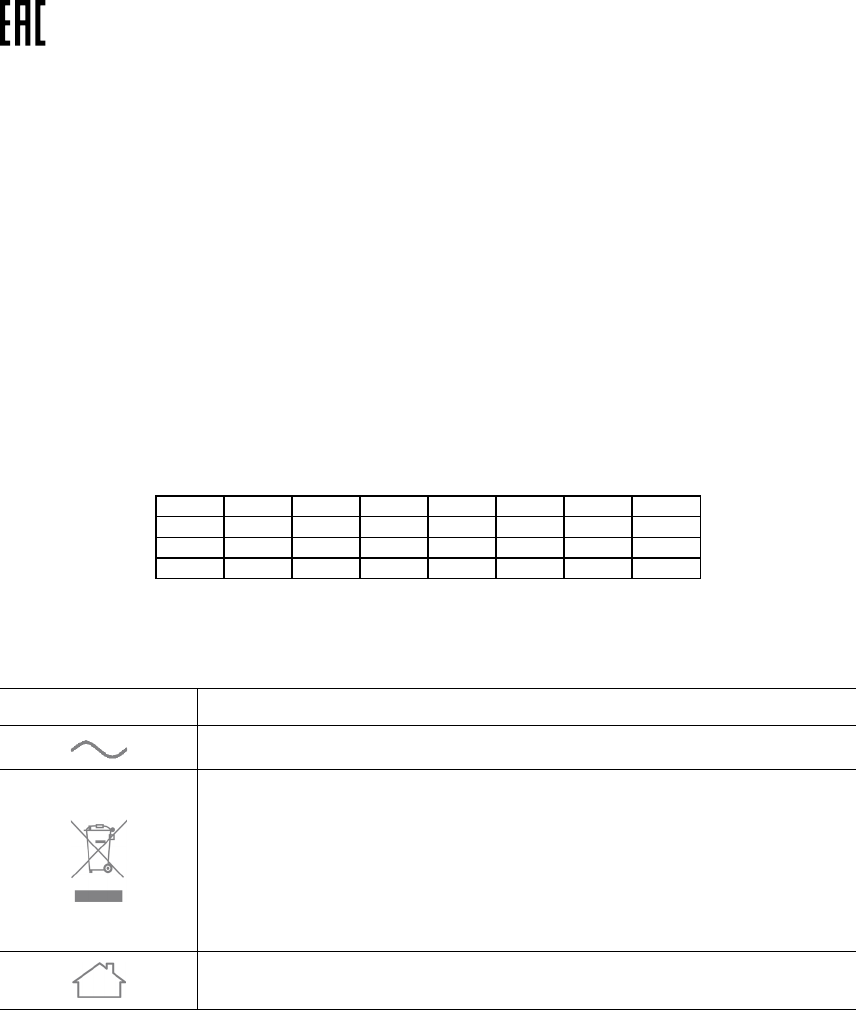
Explanation of the symbols on the product label
Symbol Explanation
AC voltage
RECYCLING
This product bears the selective sorting symbol for Waste electrical and electronic
equipment (WEEE). This means that this product must be handled pursuant to
European directive 2012/19/EU in order to be recycled or dismantled to minimize its
impact on the environment.
User has the choice to give his product to a competent recycling organization or to the
retailer when he buys a new electrical or electronic equipment.
Indoor use only

TP-LINK TECHNOLOGIES CO., LTD
Building 24 (floors 1, 3, 4, 5), and 28 (floors 1-4) Central Science
and Technology Park, Shennan Rd, Nanshan, Shenzhen, China
TP-LINK TECHNOLOGIES CO., LTD
DECLARATION OF CONFORMITY
For the following equipment:
Product Description: AV1200 Gigabit Passthrough Powerline ac Wi-Fi Extender
Model No.: TL-WPA8630P
Trademark: TP-LINK
We declare under our own responsibility that the above products satisfy all the technical regulations
applicable to the product within the scope of Council Directives:
Directives 2004/108/EC, Directives 2006/95/EC, Directives 2011/65/EU, Directives 1999/5/EC,
Directives 1999/519/EC
The above product is in conformity with the following standards or other normative documents
EN 55022: 2010 + AC: 2011
EN 60950-1: 2006 + A11: 2009 + A1: 2010 + A12: 2011 +A2: 2013
EN 50412-2-1: 2005
EN 62311: 2008
EN 300 328 V1.8.1
EN 301 489-1 V1.9.2 & EN 301 489-17 V2.2.1
The product carries the CE Mark:
Person responsible for making this declaration:
Yang Hongliang
Product Manager of International Business Date of issue: 2015-11-25