TP Link Technologies WR841NV14 300Mbps Wireless N Router User Manual TE7WR841NV14

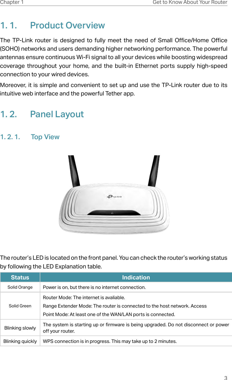
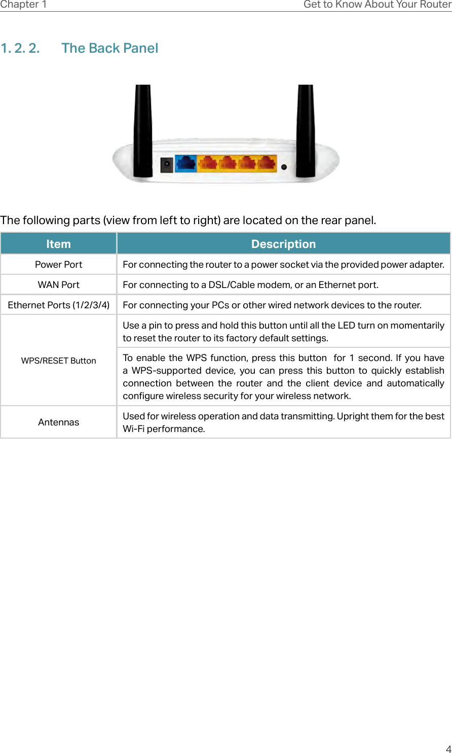
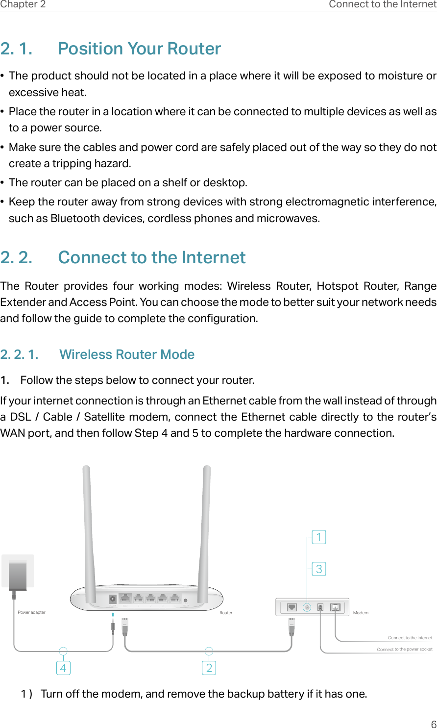
TP-Link Technologies Co., Ltd. 300Mbps Wireless N Router TE7WR841NV14

TE7WR841NV14 User Manual

REV14.0.0     1910012318User Guide300Mbps Wireless N RouterTL-WR841N
ContentsAbout This Guide .........................................................................................................1Chapter 1.  Get to Know About Your Router  . . . . . . . . . . . . . . . . . . . . . . . . . . .21. 1.  Product Overview. . . . . . . . . . . . . . . . . . . . . . . . . . . . . . . . . . . . . . . . . . . . . . . . . . . . . . . . . . . . 31. 2.  Panel Layout. . . . . . . . . . . . . . . . . . . . . . . . . . . . . . . . . . . . . . . . . . . . . . . . . . . . . . . . . . . . . . . . . 31. 2. 1. Top View  . . . . . . . . . . . . . . . . . . . . . . . . . . . . . . . . . . . . . . . . . . . . . . . . . . . . . . . . . . . . . . 31. 2. 2. The Back Panel. . . . . . . . . . . . . . . . . . . . . . . . . . . . . . . . . . . . . . . . . . . . . . . . . . . . . . . . 4Chapter 2.  Connect to the Internet  . . . . . . . . . . . . . . . . . . . . . . . . . . . . . . . . . . .62. 1.  Position Your Router  . . . . . . . . . . . . . . . . . . . . . . . . . . . . . . . . . . . . . . . . . . . . . . . . . . . . . . . . . 72. 2.  Connect to the Internet . . . . . . . . . . . . . . . . . . . . . . . . . . . . . . . . . . . . . . . . . . . . . . . . . . . . . . 72. 2. 1. Wireless Router Mode . . . . . . . . . . . . . . . . . . . . . . . . . . . . . . . . . . . . . . . . . . . . . . . . . 72. 2. 2. Hotspot Router Mode  . . . . . . . . . . . . . . . . . . . . . . . . . . . . . . . . . . . . . . . . . . . . . . . . 102. 2. 3. Range Extender Mode. . . . . . . . . . . . . . . . . . . . . . . . . . . . . . . . . . . . . . . . . . . . . . . . 112. 2. 4. Access Point Mode. . . . . . . . . . . . . . . . . . . . . . . . . . . . . . . . . . . . . . . . . . . . . . . . . . . 11Chapter 3.  Log In to the Router . . . . . . . . . . . . . . . . . . . . . . . . . . . . . . . . . . . . .  13Chapter 4.  Configure the Router in Wireless Router Mode  . . . . . . . . . .  154. 1.  Status  . . . . . . . . . . . . . . . . . . . . . . . . . . . . . . . . . . . . . . . . . . . . . . . . . . . . . . . . . . . . . . . . . . . . . . 164. 2.  Operation Mode  . . . . . . . . . . . . . . . . . . . . . . . . . . . . . . . . . . . . . . . . . . . . . . . . . . . . . . . . . . . . 174. 3.  Network  . . . . . . . . . . . . . . . . . . . . . . . . . . . . . . . . . . . . . . . . . . . . . . . . . . . . . . . . . . . . . . . . . . . . 184. 3. 1.  WAN. . . . . . . . . . . . . . . . . . . . . . . . . . . . . . . . . . . . . . . . . . . . . . . . . . . . . . . . . . . . . . . . 184. 3. 2.  LAN   . . . . . . . . . . . . . . . . . . . . . . . . . . . . . . . . . . . . . . . . . . . . . . . . . . . . . . . . . . . . . . . 254. 3. 3.  IPTV. . . . . . . . . . . . . . . . . . . . . . . . . . . . . . . . . . . . . . . . . . . . . . . . . . . . . . . . . . . . . . . . 254. 3. 4. MAC Clone . . . . . . . . . . . . . . . . . . . . . . . . . . . . . . . . . . . . . . . . . . . . . . . . . . . . . . . . . . . 264. 4.  Wireless . . . . . . . . . . . . . . . . . . . . . . . . . . . . . . . . . . . . . . . . . . . . . . . . . . . . . . . . . . . . . . . . . . . . 274. 4. 1. Wireless Settings  . . . . . . . . . . . . . . . . . . . . . . . . . . . . . . . . . . . . . . . . . . . . . . . . . . . . 274. 4. 2.  WPS. . . . . . . . . . . . . . . . . . . . . . . . . . . . . . . . . . . . . . . . . . . . . . . . . . . . . . . . . . . . . . . . 284. 4. 3. Wireless Security  . . . . . . . . . . . . . . . . . . . . . . . . . . . . . . . . . . . . . . . . . . . . . . . . . . . . 294. 4. 4. Wireless MAC Filtering  . . . . . . . . . . . . . . . . . . . . . . . . . . . . . . . . . . . . . . . . . . . . . . . 314. 4. 5. Wireless Advanced. . . . . . . . . . . . . . . . . . . . . . . . . . . . . . . . . . . . . . . . . . . . . . . . . . . 324. 4. 6. Wireless Statistics  . . . . . . . . . . . . . . . . . . . . . . . . . . . . . . . . . . . . . . . . . . . . . . . . . . . 344. 5.  Guest Network. . . . . . . . . . . . . . . . . . . . . . . . . . . . . . . . . . . . . . . . . . . . . . . . . . . . . . . . . . . . . . 344. 6.  DHCP. . . . . . . . . . . . . . . . . . . . . . . . . . . . . . . . . . . . . . . . . . . . . . . . . . . . . . . . . . . . . . . . . . . . . . . 35
4. 6. 1. DHCP Settings  . . . . . . . . . . . . . . . . . . . . . . . . . . . . . . . . . . . . . . . . . . . . . . . . . . . . . . . 364. 6. 2. DHCP Clients List  . . . . . . . . . . . . . . . . . . . . . . . . . . . . . . . . . . . . . . . . . . . . . . . . . . . . 374. 6. 3. Address Reservation  . . . . . . . . . . . . . . . . . . . . . . . . . . . . . . . . . . . . . . . . . . . . . . . . . 374. 7.  Forwarding  . . . . . . . . . . . . . . . . . . . . . . . . . . . . . . . . . . . . . . . . . . . . . . . . . . . . . . . . . . . . . . . . . 384. 7. 1. Virtual Server  . . . . . . . . . . . . . . . . . . . . . . . . . . . . . . . . . . . . . . . . . . . . . . . . . . . . . . . . 384. 7. 2. Port Triggering  . . . . . . . . . . . . . . . . . . . . . . . . . . . . . . . . . . . . . . . . . . . . . . . . . . . . . . . 394. 7. 3.  DMZ. . . . . . . . . . . . . . . . . . . . . . . . . . . . . . . . . . . . . . . . . . . . . . . . . . . . . . . . . . . . . . . . 404. 7. 4.  UPnP. . . . . . . . . . . . . . . . . . . . . . . . . . . . . . . . . . . . . . . . . . . . . . . . . . . . . . . . . . . . . . . . 414. 8.  Security  . . . . . . . . . . . . . . . . . . . . . . . . . . . . . . . . . . . . . . . . . . . . . . . . . . . . . . . . . . . . . . . . . . . . 424. 8. 1. Basic Security. . . . . . . . . . . . . . . . . . . . . . . . . . . . . . . . . . . . . . . . . . . . . . . . . . . . . . . . 424. 8. 2. Advanced Security . . . . . . . . . . . . . . . . . . . . . . . . . . . . . . . . . . . . . . . . . . . . . . . . . . . 444. 8. 3. Local Management. . . . . . . . . . . . . . . . . . . . . . . . . . . . . . . . . . . . . . . . . . . . . . . . . . . 454. 8. 4. Remote Management  . . . . . . . . . . . . . . . . . . . . . . . . . . . . . . . . . . . . . . . . . . . . . . . . 464. 9.  Parental Controls  . . . . . . . . . . . . . . . . . . . . . . . . . . . . . . . . . . . . . . . . . . . . . . . . . . . . . . . . . . . 474. 10.  Access Control  . . . . . . . . . . . . . . . . . . . . . . . . . . . . . . . . . . . . . . . . . . . . . . . . . . . . . . . . . . . . . 484. 11.  Advanced Routing  . . . . . . . . . . . . . . . . . . . . . . . . . . . . . . . . . . . . . . . . . . . . . . . . . . . . . . . . . . 514. 11. 1. Static Route List  . . . . . . . . . . . . . . . . . . . . . . . . . . . . . . . . . . . . . . . . . . . . . . . . . . . . 514. 11. 2. System Routing Table . . . . . . . . . . . . . . . . . . . . . . . . . . . . . . . . . . . . . . . . . . . . . . . 524. 12.  Bandwidth Control . . . . . . . . . . . . . . . . . . . . . . . . . . . . . . . . . . . . . . . . . . . . . . . . . . . . . . . . . . 524. 13.  IP & MAC Binding  . . . . . . . . . . . . . . . . . . . . . . . . . . . . . . . . . . . . . . . . . . . . . . . . . . . . . . . . . . . 544. 13. 1. Binding Settings  . . . . . . . . . . . . . . . . . . . . . . . . . . . . . . . . . . . . . . . . . . . . . . . . . . . . 544. 13. 2. ARP List  . . . . . . . . . . . . . . . . . . . . . . . . . . . . . . . . . . . . . . . . . . . . . . . . . . . . . . . . . . . . 544. 14.  Dynamic DNS. . . . . . . . . . . . . . . . . . . . . . . . . . . . . . . . . . . . . . . . . . . . . . . . . . . . . . . . . . . . . . . 554. 15.  IPv6  . . . . . . . . . . . . . . . . . . . . . . . . . . . . . . . . . . . . . . . . . . . . . . . . . . . . . . . . . . . . . . . . . . . . . . . . 584. 15. 1. IPv6 Status  . . . . . . . . . . . . . . . . . . . . . . . . . . . . . . . . . . . . . . . . . . . . . . . . . . . . . . . . . 584. 15. 2. IPv6 WAN . . . . . . . . . . . . . . . . . . . . . . . . . . . . . . . . . . . . . . . . . . . . . . . . . . . . . . . . . . . 584. 15. 3. IPv6 LAN. . . . . . . . . . . . . . . . . . . . . . . . . . . . . . . . . . . . . . . . . . . . . . . . . . . . . . . . . . . . 624. 16.  System Tools  . . . . . . . . . . . . . . . . . . . . . . . . . . . . . . . . . . . . . . . . . . . . . . . . . . . . . . . . . . . . . . . 624. 16. 1. Time Settings . . . . . . . . . . . . . . . . . . . . . . . . . . . . . . . . . . . . . . . . . . . . . . . . . . . . . . . 624. 16. 2. Diagnostic . . . . . . . . . . . . . . . . . . . . . . . . . . . . . . . . . . . . . . . . . . . . . . . . . . . . . . . . . . 644. 16. 3. Firmware Upgrade  . . . . . . . . . . . . . . . . . . . . . . . . . . . . . . . . . . . . . . . . . . . . . . . . . . 654. 16. 4. Factory Defaults  . . . . . . . . . . . . . . . . . . . . . . . . . . . . . . . . . . . . . . . . . . . . . . . . . . . . 654. 16. 5. Backup & Restore . . . . . . . . . . . . . . . . . . . . . . . . . . . . . . . . . . . . . . . . . . . . . . . . . . . 664. 16. 6. Reboot  . . . . . . . . . . . . . . . . . . . . . . . . . . . . . . . . . . . . . . . . . . . . . . . . . . . . . . . . . . . . . 664. 16. 7. Password . . . . . . . . . . . . . . . . . . . . . . . . . . . . . . . . . . . . . . . . . . . . . . . . . . . . . . . . . . . 684. 16. 8. System Log. . . . . . . . . . . . . . . . . . . . . . . . . . . . . . . . . . . . . . . . . . . . . . . . . . . . . . . . . 694. 16. 9. Statistics  . . . . . . . . . . . . . . . . . . . . . . . . . . . . . . . . . . . . . . . . . . . . . . . . . . . . . . . . . . . 694. 17.  Logout  . . . . . . . . . . . . . . . . . . . . . . . . . . . . . . . . . . . . . . . . . . . . . . . . . . . . . . . . . . . . . . . . . . . . . 69
Chapter 5.  Configure the Router in Hotspot Router Mode. . . . . . . . . . .  705. 1.  Status  . . . . . . . . . . . . . . . . . . . . . . . . . . . . . . . . . . . . . . . . . . . . . . . . . . . . . . . . . . . . . . . . . . . . . . 715. 2.  Operation Mode  . . . . . . . . . . . . . . . . . . . . . . . . . . . . . . . . . . . . . . . . . . . . . . . . . . . . . . . . . . . . 725. 3.  Network  . . . . . . . . . . . . . . . . . . . . . . . . . . . . . . . . . . . . . . . . . . . . . . . . . . . . . . . . . . . . . . . . . . . . 735. 3. 1.  WAN. . . . . . . . . . . . . . . . . . . . . . . . . . . . . . . . . . . . . . . . . . . . . . . . . . . . . . . . . . . . . . . . 735. 3. 2.  LAN   . . . . . . . . . . . . . . . . . . . . . . . . . . . . . . . . . . . . . . . . . . . . . . . . . . . . . . . . . . . . . . . 805. 3. 3. MAC Clone . . . . . . . . . . . . . . . . . . . . . . . . . . . . . . . . . . . . . . . . . . . . . . . . . . . . . . . . . . . 805. 4.  Wireless . . . . . . . . . . . . . . . . . . . . . . . . . . . . . . . . . . . . . . . . . . . . . . . . . . . . . . . . . . . . . . . . . . . . 815. 4. 1. Wireless Settings  . . . . . . . . . . . . . . . . . . . . . . . . . . . . . . . . . . . . . . . . . . . . . . . . . . . . 815. 4. 2.  WPS. . . . . . . . . . . . . . . . . . . . . . . . . . . . . . . . . . . . . . . . . . . . . . . . . . . . . . . . . . . . . . . . 825. 4. 3. Wireless Security  . . . . . . . . . . . . . . . . . . . . . . . . . . . . . . . . . . . . . . . . . . . . . . . . . . . . 845. 4. 4. Wireless MAC Filtering  . . . . . . . . . . . . . . . . . . . . . . . . . . . . . . . . . . . . . . . . . . . . . . . 865. 4. 5. Wireless Advanced. . . . . . . . . . . . . . . . . . . . . . . . . . . . . . . . . . . . . . . . . . . . . . . . . . . 875. 4. 6. Wireless Statistics  . . . . . . . . . . . . . . . . . . . . . . . . . . . . . . . . . . . . . . . . . . . . . . . . . . . 885. 5.  Guest Network. . . . . . . . . . . . . . . . . . . . . . . . . . . . . . . . . . . . . . . . . . . . . . . . . . . . . . . . . . . . . . 895. 6.  DHCP. . . . . . . . . . . . . . . . . . . . . . . . . . . . . . . . . . . . . . . . . . . . . . . . . . . . . . . . . . . . . . . . . . . . . . . 905. 6. 1. DHCP Settings  . . . . . . . . . . . . . . . . . . . . . . . . . . . . . . . . . . . . . . . . . . . . . . . . . . . . . . . 905. 6. 2. DHCP Clients List  . . . . . . . . . . . . . . . . . . . . . . . . . . . . . . . . . . . . . . . . . . . . . . . . . . . . 915. 6. 3. Address Reservation  . . . . . . . . . . . . . . . . . . . . . . . . . . . . . . . . . . . . . . . . . . . . . . . . . 925. 7.  Forwarding  . . . . . . . . . . . . . . . . . . . . . . . . . . . . . . . . . . . . . . . . . . . . . . . . . . . . . . . . . . . . . . . . . 925. 7. 1. Virtual Server  . . . . . . . . . . . . . . . . . . . . . . . . . . . . . . . . . . . . . . . . . . . . . . . . . . . . . . . . 935. 7. 2. Port Triggering  . . . . . . . . . . . . . . . . . . . . . . . . . . . . . . . . . . . . . . . . . . . . . . . . . . . . . . . 945. 7. 3.  DMZ. . . . . . . . . . . . . . . . . . . . . . . . . . . . . . . . . . . . . . . . . . . . . . . . . . . . . . . . . . . . . . . . 955. 7. 4.  UPnP. . . . . . . . . . . . . . . . . . . . . . . . . . . . . . . . . . . . . . . . . . . . . . . . . . . . . . . . . . . . . . . . 965. 8.  Security  . . . . . . . . . . . . . . . . . . . . . . . . . . . . . . . . . . . . . . . . . . . . . . . . . . . . . . . . . . . . . . . . . . . . 975. 8. 1. Basic Security. . . . . . . . . . . . . . . . . . . . . . . . . . . . . . . . . . . . . . . . . . . . . . . . . . . . . . . . 975. 8. 2. Advanced Security . . . . . . . . . . . . . . . . . . . . . . . . . . . . . . . . . . . . . . . . . . . . . . . . . . . 985. 8. 3. Local Management. . . . . . . . . . . . . . . . . . . . . . . . . . . . . . . . . . . . . . . . . . . . . . . . . .1005. 8. 4. Remote Management  . . . . . . . . . . . . . . . . . . . . . . . . . . . . . . . . . . . . . . . . . . . . . . .1005. 9.  Parental Controls  . . . . . . . . . . . . . . . . . . . . . . . . . . . . . . . . . . . . . . . . . . . . . . . . . . . . . . . . . .1015. 10.  Access Control  . . . . . . . . . . . . . . . . . . . . . . . . . . . . . . . . . . . . . . . . . . . . . . . . . . . . . . . . . . . .1025. 11.  Advanced Routing  . . . . . . . . . . . . . . . . . . . . . . . . . . . . . . . . . . . . . . . . . . . . . . . . . . . . . . . . .1055. 11. 1. Static Route List  . . . . . . . . . . . . . . . . . . . . . . . . . . . . . . . . . . . . . . . . . . . . . . . . . . .1055. 11. 2. System Routing Table . . . . . . . . . . . . . . . . . . . . . . . . . . . . . . . . . . . . . . . . . . . . . .1065. 12.  Bandwidth Control . . . . . . . . . . . . . . . . . . . . . . . . . . . . . . . . . . . . . . . . . . . . . . . . . . . . . . . . .1075. 13.  IP & MAC Binding  . . . . . . . . . . . . . . . . . . . . . . . . . . . . . . . . . . . . . . . . . . . . . . . . . . . . . . . . . .1085. 13. 1. Binding Settings  . . . . . . . . . . . . . . . . . . . . . . . . . . . . . . . . . . . . . . . . . . . . . . . . . . .1085. 13. 2. ARP List  . . . . . . . . . . . . . . . . . . . . . . . . . . . . . . . . . . . . . . . . . . . . . . . . . . . . . . . . . . .1095. 14.  Dynamic DNS. . . . . . . . . . . . . . . . . . . . . . . . . . . . . . . . . . . . . . . . . . . . . . . . . . . . . . . . . . . . . .110
5. 15.  IPv6  . . . . . . . . . . . . . . . . . . . . . . . . . . . . . . . . . . . . . . . . . . . . . . . . . . . . . . . . . . . . . . . . . . . . . . .1125. 15. 1. IPv6 Status  . . . . . . . . . . . . . . . . . . . . . . . . . . . . . . . . . . . . . . . . . . . . . . . . . . . . . . . .1125. 15. 2. IPv6 WAN . . . . . . . . . . . . . . . . . . . . . . . . . . . . . . . . . . . . . . . . . . . . . . . . . . . . . . . . . .1135. 15. 3. IPv6 LAN. . . . . . . . . . . . . . . . . . . . . . . . . . . . . . . . . . . . . . . . . . . . . . . . . . . . . . . . . . .1165. 16.  System Tools  . . . . . . . . . . . . . . . . . . . . . . . . . . . . . . . . . . . . . . . . . . . . . . . . . . . . . . . . . . . . . .1175. 16. 1. Time Settings . . . . . . . . . . . . . . . . . . . . . . . . . . . . . . . . . . . . . . . . . . . . . . . . . . . . . .1175. 16. 2. Diagnostic . . . . . . . . . . . . . . . . . . . . . . . . . . . . . . . . . . . . . . . . . . . . . . . . . . . . . . . . .1185. 16. 3. Firmware Upgrade  . . . . . . . . . . . . . . . . . . . . . . . . . . . . . . . . . . . . . . . . . . . . . . . . .1205. 16. 4. Factory Defaults  . . . . . . . . . . . . . . . . . . . . . . . . . . . . . . . . . . . . . . . . . . . . . . . . . . .1205. 16. 5. Backup & Restore . . . . . . . . . . . . . . . . . . . . . . . . . . . . . . . . . . . . . . . . . . . . . . . . . .1205. 16. 6. Reboot  . . . . . . . . . . . . . . . . . . . . . . . . . . . . . . . . . . . . . . . . . . . . . . . . . . . . . . . . . . . .1215. 16. 7. Password . . . . . . . . . . . . . . . . . . . . . . . . . . . . . . . . . . . . . . . . . . . . . . . . . . . . . . . . . .1235. 16. 8. System Log. . . . . . . . . . . . . . . . . . . . . . . . . . . . . . . . . . . . . . . . . . . . . . . . . . . . . . . .1235. 16. 9. Statistics  . . . . . . . . . . . . . . . . . . . . . . . . . . . . . . . . . . . . . . . . . . . . . . . . . . . . . . . . . .1245. 17.  Logout  . . . . . . . . . . . . . . . . . . . . . . . . . . . . . . . . . . . . . . . . . . . . . . . . . . . . . . . . . . . . . . . . . . . .124Chapter 6.  Configure the Router in Access Point Mode  . . . . . . . . . . . . 1256. 1.  Status  . . . . . . . . . . . . . . . . . . . . . . . . . . . . . . . . . . . . . . . . . . . . . . . . . . . . . . . . . . . . . . . . . . . . .1266. 2.  Operation Mode  . . . . . . . . . . . . . . . . . . . . . . . . . . . . . . . . . . . . . . . . . . . . . . . . . . . . . . . . . . .1276. 3.  Network  . . . . . . . . . . . . . . . . . . . . . . . . . . . . . . . . . . . . . . . . . . . . . . . . . . . . . . . . . . . . . . . . . . .1276. 3. 1.  LAN   . . . . . . . . . . . . . . . . . . . . . . . . . . . . . . . . . . . . . . . . . . . . . . . . . . . . . . . . . . . . . .1276. 4.  Wireless . . . . . . . . . . . . . . . . . . . . . . . . . . . . . . . . . . . . . . . . . . . . . . . . . . . . . . . . . . . . . . . . . . .1286. 4. 1. Basic Settings. . . . . . . . . . . . . . . . . . . . . . . . . . . . . . . . . . . . . . . . . . . . . . . . . . . . . . .1286. 4. 2.  WPS. . . . . . . . . . . . . . . . . . . . . . . . . . . . . . . . . . . . . . . . . . . . . . . . . . . . . . . . . . . . . . .1296. 4. 3. Wireless Security  . . . . . . . . . . . . . . . . . . . . . . . . . . . . . . . . . . . . . . . . . . . . . . . . . . .1306. 4. 4. Wireless MAC Filtering  . . . . . . . . . . . . . . . . . . . . . . . . . . . . . . . . . . . . . . . . . . . . . .1326. 4. 5. Wireless Advanced. . . . . . . . . . . . . . . . . . . . . . . . . . . . . . . . . . . . . . . . . . . . . . . . . .1336. 4. 6. Wireless Statistics  . . . . . . . . . . . . . . . . . . . . . . . . . . . . . . . . . . . . . . . . . . . . . . . . . .1356. 4. 7. Throughput Monitor . . . . . . . . . . . . . . . . . . . . . . . . . . . . . . . . . . . . . . . . . . . . . . . . .1356. 5.  DHCP. . . . . . . . . . . . . . . . . . . . . . . . . . . . . . . . . . . . . . . . . . . . . . . . . . . . . . . . . . . . . . . . . . . . . .1366. 5. 1. DHCP Settings  . . . . . . . . . . . . . . . . . . . . . . . . . . . . . . . . . . . . . . . . . . . . . . . . . . . . . .1366. 5. 2. DHCP Clients List  . . . . . . . . . . . . . . . . . . . . . . . . . . . . . . . . . . . . . . . . . . . . . . . . . . .1376. 5. 3. Address Reservation  . . . . . . . . . . . . . . . . . . . . . . . . . . . . . . . . . . . . . . . . . . . . . . . .1386. 6.  System Tools  . . . . . . . . . . . . . . . . . . . . . . . . . . . . . . . . . . . . . . . . . . . . . . . . . . . . . . . . . . . . . .1386. 6. 1. Time Settings  . . . . . . . . . . . . . . . . . . . . . . . . . . . . . . . . . . . . . . . . . . . . . . . . . . . . . . .1386. 6. 2. Diagnostic  . . . . . . . . . . . . . . . . . . . . . . . . . . . . . . . . . . . . . . . . . . . . . . . . . . . . . . . . . .1406. 6. 3. SNMP Settings . . . . . . . . . . . . . . . . . . . . . . . . . . . . . . . . . . . . . . . . . . . . . . . . . . . . . .1416. 6. 4. Ping WatchDog  . . . . . . . . . . . . . . . . . . . . . . . . . . . . . . . . . . . . . . . . . . . . . . . . . . . . .142
6. 6. 5. Firmware Upgrade. . . . . . . . . . . . . . . . . . . . . . . . . . . . . . . . . . . . . . . . . . . . . . . . . . .1436. 6. 6. Factory Defaults  . . . . . . . . . . . . . . . . . . . . . . . . . . . . . . . . . . . . . . . . . . . . . . . . . . . .1436. 6. 7. Backup & Restore  . . . . . . . . . . . . . . . . . . . . . . . . . . . . . . . . . . . . . . . . . . . . . . . . . . .1446. 6. 8. Reboot . . . . . . . . . . . . . . . . . . . . . . . . . . . . . . . . . . . . . . . . . . . . . . . . . . . . . . . . . . . . . .1446. 6. 9. Password  . . . . . . . . . . . . . . . . . . . . . . . . . . . . . . . . . . . . . . . . . . . . . . . . . . . . . . . . . . .1466. 6. 10. System Log. . . . . . . . . . . . . . . . . . . . . . . . . . . . . . . . . . . . . . . . . . . . . . . . . . . . . . . .1466. 7.  Logout  . . . . . . . . . . . . . . . . . . . . . . . . . . . . . . . . . . . . . . . . . . . . . . . . . . . . . . . . . . . . . . . . . . . .147Chapter 7.  Configure the Router in Range Extender Mode  . . . . . . . . . 1487. 1.  Status  . . . . . . . . . . . . . . . . . . . . . . . . . . . . . . . . . . . . . . . . . . . . . . . . . . . . . . . . . . . . . . . . . . . . .1497. 2.  Operation Mode  . . . . . . . . . . . . . . . . . . . . . . . . . . . . . . . . . . . . . . . . . . . . . . . . . . . . . . . . . . .1507. 3.  Network  . . . . . . . . . . . . . . . . . . . . . . . . . . . . . . . . . . . . . . . . . . . . . . . . . . . . . . . . . . . . . . . . . . .1507. 3. 1.  LAN   . . . . . . . . . . . . . . . . . . . . . . . . . . . . . . . . . . . . . . . . . . . . . . . . . . . . . . . . . . . . . .1507. 4.  Wireless . . . . . . . . . . . . . . . . . . . . . . . . . . . . . . . . . . . . . . . . . . . . . . . . . . . . . . . . . . . . . . . . . . .1517. 4. 1. Connect to Network. . . . . . . . . . . . . . . . . . . . . . . . . . . . . . . . . . . . . . . . . . . . . . . . .1517. 4. 2. Extended Network  . . . . . . . . . . . . . . . . . . . . . . . . . . . . . . . . . . . . . . . . . . . . . . . . . .1527. 4. 3. Wireless MAC Filtering  . . . . . . . . . . . . . . . . . . . . . . . . . . . . . . . . . . . . . . . . . . . . . .1527. 4. 4. Wireless Advanced. . . . . . . . . . . . . . . . . . . . . . . . . . . . . . . . . . . . . . . . . . . . . . . . . .1547. 4. 5. Wireless Statistics  . . . . . . . . . . . . . . . . . . . . . . . . . . . . . . . . . . . . . . . . . . . . . . . . . .1557. 5.  DHCP. . . . . . . . . . . . . . . . . . . . . . . . . . . . . . . . . . . . . . . . . . . . . . . . . . . . . . . . . . . . . . . . . . . . . .1557. 5. 1. DHCP Settings  . . . . . . . . . . . . . . . . . . . . . . . . . . . . . . . . . . . . . . . . . . . . . . . . . . . . . .1557. 5. 2. DHCP Clients List  . . . . . . . . . . . . . . . . . . . . . . . . . . . . . . . . . . . . . . . . . . . . . . . . . . .1577. 6.  System Tools  . . . . . . . . . . . . . . . . . . . . . . . . . . . . . . . . . . . . . . . . . . . . . . . . . . . . . . . . . . . . . .1587. 6. 1. Time Settings  . . . . . . . . . . . . . . . . . . . . . . . . . . . . . . . . . . . . . . . . . . . . . . . . . . . . . . .1587. 6. 2. Diagnostic  . . . . . . . . . . . . . . . . . . . . . . . . . . . . . . . . . . . . . . . . . . . . . . . . . . . . . . . . . .1597. 6. 3. Firmware Upgrade. . . . . . . . . . . . . . . . . . . . . . . . . . . . . . . . . . . . . . . . . . . . . . . . . . .1607. 6. 4. Factory Defaults  . . . . . . . . . . . . . . . . . . . . . . . . . . . . . . . . . . . . . . . . . . . . . . . . . . . .1607. 6. 5. Backup & Restore  . . . . . . . . . . . . . . . . . . . . . . . . . . . . . . . . . . . . . . . . . . . . . . . . . . .1617. 6. 6. Reboot . . . . . . . . . . . . . . . . . . . . . . . . . . . . . . . . . . . . . . . . . . . . . . . . . . . . . . . . . . . . . .1617. 6. 7. Password  . . . . . . . . . . . . . . . . . . . . . . . . . . . . . . . . . . . . . . . . . . . . . . . . . . . . . . . . . . .1637. 6. 8. System Log  . . . . . . . . . . . . . . . . . . . . . . . . . . . . . . . . . . . . . . . . . . . . . . . . . . . . . . . . .1637. 7.  Logout  . . . . . . . . . . . . . . . . . . . . . . . . . . . . . . . . . . . . . . . . . . . . . . . . . . . . . . . . . . . . . . . . . . . .164FAQ ............................................................................................................................. 165
1About This GuideThis guide is a complement to Quick Installation Guide. The Quick Installation Guide provides instructions for quick internet setup, while this guide contains details of each function and demonstrates how to configure them. When using this guide, please notice that features of the router may vary slightly depending on the model and software version you have, and on your location, language, and internet service provider. All screenshots, images, parameters and descriptions documented in this guide are used for demonstration only.ConventionsIn this guide the following conventions are used:Convention DescriptionUnderlined Underlined words or phrases are hyperlinks. You can click to redirect to a website or a specific section.Teal Contents to be emphasized and texts on the web page are in teal, including the menus, items, buttons and so on.>The menu structures to show the path to load the corresponding page. For example, Advanced > Wireless > MAC Filtering means the MAC Filtering function page is under the Wireless menu that is located in the Advanced tab.Note: Ignoring this type of note might result in a malfunction or damage to the device.Tips: Indicates important information that helps you make better use of your device.More InfoThe latest software, management app and utility are available from the Download Center at www.tp-link.com/support.The Quick Installation Guide can be found where you find this guide or inside the package of the router.Specifications can be found on the product page at http://www.tp-link.com.A Technical Support Forum is provided for you to discuss our products at  http://forum.tp-link.com.Our Technical Support contact information can be found at the Contact Technical Support page at www.tp-link.com/support.
Chapter 1Get to Know About Your RouterThis chapter introduces what the router can do and shows its appearance. It contains the following sections:•  Product Overview•  Panel Layout
3Chapter 1 Get to Know About Your Router1. 1.  Product OverviewThe TP-Link router is designed to fully meet the need of Small Office/Home Office (SOHO) networks and users demanding higher networking performance. The powerful antennas ensure continuous Wi-Fi signal to all your devices while boosting widespread coverage throughout your home, and the built-in Ethernet ports supply high-speed connection to your wired devices.Moreover, it is simple and convenient to set up and use the TP-Link router due to its intuitive web interface and the powerful Tether app.1. 2.  Panel Layout1. 2. 1.  Top ViewThe router’s LED is located on the front panel. You can check the router’s working status by following the LED Explanation table.Status IndicationSolid Orange Power is on, but there is no internet connection.Solid GreenRouter Mode: The internet is avaliable.Range Extender Mode: The router is connected to the host network. Access Point Mode: At least one of the WAN/LAN ports is connected.Blinking slowly The system is starting up or firmware is being upgraded. Do not disconnect or power off your router.Blinking quickly WPS connection is in progress. This may take up to 2 minutes.
4Chapter 1 Get to Know About Your Router1. 2. 2.  The Back PanelThe following parts (view from left to right) are located on the rear panel. Item DescriptionPower Port For connecting the router to a power socket via the provided power adapter.WAN Port For connecting to a DSL/Cable modem, or an Ethernet port.Ethernet Ports (1/2/3/4) For connecting your PCs or other wired network devices to the router.WPS/RESET ButtonUse a pin to press and hold this button until all the LED turn on momentarily to reset the router to its factory default settings.To enable the WPS function, press this button  for 1 second. If you have a WPS-supported device, you can press this button to quickly establish connection between the router and the client device and automatically configure wireless security for your wireless network.Antennas Used for wireless operation and data transmitting. Upright them for the best Wi-Fi performance.
Chapter 2Connect to the InternetThis chapter contains the following sections:•  Position Your Router•  Connect to the Internet
6Chapter 2 Connect to the Internet2. 1.  Position Your Router•  The product should not be located in a place where it will be exposed to moisture or excessive heat.•  Place the router in a location where it can be connected to multiple devices as well as to a power source.•  Make sure the cables and power cord are safely placed out of the way so they do not create a tripping hazard.•  The router can be placed on a shelf or desktop.•  Keep the router away from strong devices with strong electromagnetic interference, such as Bluetooth devices, cordless phones and microwaves.2. 2.  Connect to the InternetThe Router provides four working modes: Wireless Router, Hotspot Router, Range Extender and Access Point. You can choose the mode to better suit your network needs and follow the guide to complete the configuration.2. 2. 1.  Wireless Router Mode1.  Follow the steps below to connect your router.If your internet connection is through an Ethernet cable from the wall instead of through a DSL / Cable / Satellite modem, connect the Ethernet cable directly to the router’s WAN port, and then follow Step 4 and 5 to complete the hardware connection.Connect to the power socketConnect to the internetModemRouterPower adapterPOWER WAN 1 2 3 4 WPS/RESETPOWER WAN 1 2 3 4 WPS/RESET1 )  Turn off the modem, and remove the backup battery if it has one.
7Chapter 2 Connect to the Internet2 )  Connect the modem to the router’s WAN port with an Ethernet cable.3 )  Turn on the modem, and then wait about 2 minutes for it to restart.4 )  Connect the power adapter to the router and turn on the router.5 )  Verify that the hardware connection is correct by checking these LEDs.PowerOnInternetOnWi-FiOn2.  Connect your computer to the router.•  Method 1: WiredTurn off the Wi-Fi on your computer and connect the devices as shown below.Ethernet cablePOWERWAN 1 2 3 4 WPS/RESETPOWERWAN 1 2 3 4 WPS/RESET•  Method 2: Wirelessly1 )  Find the SSID (Network Name) and Wireless Password printed on the label at the bottom of the router.2 )  Click the network icon of your computer or go to Wi-Fi Settings of your smart device, and then select the SSID to join the network.ORConnections are availableWireless Network ConnectionTP-Link_XXXXConnect automatically ConnectWi-FiWi-Fi TP-Link_XXXXCHOOSE A NETWORK...Other...< SettingsSmart DeviceComputer•  Method 3: Use the WPS buttonWireless devices that support WPS, including Android phones, tablets, most USB network cards, can be connected to your router through this method.Note:•  WPS is not supported by iOS devices.
8Chapter 2 Connect to the Internet•  The WPS function cannot be configured if the wireless function of the router is disabled. Also, the WPS function will be disabled if your wireless encryption is WEP. Please make sure the wireless function is enabled and is configured with the appropriate encryption before configuring the WPS.1 )  Tab the WPS icon on the device’s screen. Here we take an Android phone as an example.2 )  Immediately press the WPS button on your router.POWER WAN 1 2 3 4 WPS/RESETPOWER WAN 1 2 3 4 WPS/RESETWLANOnTP-LinkHomeNetworkOceTP-Link_123TP-Link_ABCMyHomeTestClose to 3.  Enter  http://tplinkwifi.net  in the address bar of a web browser. Use admin for username and password, and then click Login.  Note:If the above screen does not pop-up, it means that your IE Web-browser has been set to a proxy. Go to menu Tools  > Internet Options > Connections > LAN Settings, in the screen that appears, untick the Using Proxy checkbox, and click OK.4.  After successfully login, select Wireless Router and follow the Quick Setup to set up the internet connection. 5.  Enjoy! For wireless devices, you may have to reconnect to the wireless network if you have customized the SSID (wireless name) and password during the configuration.
9Chapter 2 Connect to the Internet2. 2. 2.  Hotspot Router ModeThis mode helps to create your personal Wi-Fi hotspot from a public Wi-Fi network. Router DevicesPublic Wi-Fi1.  Connect the power adapter to the router and turn on the router.2.  Connect a computer to the router via an Ethernet cable or wirelessly by using the SSID (wireless name) and password printed on the bottom label of the router.3.  Enter http://tplinkwifi.net in the address bar of a web browser. Use admin for both username and password, and then click Login.4.  After successfully login, select Hotspot Router mode and follow the Quick Setup to set up the internet connection. 5.  Enjoy! Connect to the wireless network by using the SSID (network name) and password of the router.2. 2. 3.  Range Extender ModeThis mode boosts your home wireless coverage. 1.  Place the router next to your host router and turn it on.
10Chapter 2 Connect to the Internet2.  Connect a computer to the router via an Ethernet cable or wirelessly by using the SSID (wireless name) and password printed on the bottom label of the router.3.  Enter http://tplinkwifi.net in the address bar of a web browser. Use admin for both username and password, and then click Login.4.  After successfully login, select Range Extender mode and follow the Quick Setup to set up the internet connection. 5.  Relocate: Place the router between your host router and the Wi-Fi dead zone. The location you choose must be within the range of your existing host network.Extended NetworkHost NetworkDevicesHost Router Router6.  Enjoy! The extended network shares the same wireless password as that of your host network, but may have different network name if you have customized it during the configuration.2. 2. 4.  Access Point ModeThis mode transforms your existing wired network to a wireless network.DevicesRouterWired RouterEthernet4Ethernet3Ethernet1Ethernet2InternetEthernet2InternetWAN
11Chapter 2 Connect to the Internet1.  Connect the power adapter to the router and turn on the router.2.  Connect the router to your wired host router’s Ethernet port via an Ethernet cable as shown above.3.  Connect a computer to the router via an Ethernet cable or wirelessly by using the SSID (network name) and password printed on the bottom label of the router.4.  Enter  http://tplinkwifi.net in the address bar of a web browser. Use admin  for username and password, and then click Login.   Note:If the above screen does not pop-up, it means that your IE Web-browser has been set to a proxy. Go to menu Tools  > Internet Options > Connections > LAN Settings, in the screen that appears, untick the Using Proxy checkbox, and click OK.5.  After successfully login, select Access Point mode and follow the Quick Setup to set up the internet connection. 6.  Enjoy!  Connect to the wireless network by using the SSID (network name) and password of the router.
Chapter 3Log In to the RouterThis chapter introduces how to log in to the Web-based Utility of the router.
13Chapter 3 Log In to the RouterWith the Web-based Utility, it is easy to configure and manage the router. The Web-based Utility can be used on any Windows, Macintosh or UNIX OS with a web browser, such as Microsoft the Internet Explorer, Mozilla Firefox or Apple Safari.Follow the steps below to log in to your router.1. Set up the TCP/IP Protocol in Obtain an IP address automatically mode on your computer.2. Visit http://tplinkwifi.net, and log in with the username and password you set for the router. The default one is admin (all lowercase) for both username and password.Note:If the login window does not appear, please refer to the FAQ section.
Chapter 4Configure the Router in Wireless Router ModeThis chapter presents how to configure the various features of the router working as a wireless router.  It contains the following sections:•  Status•  Operation Mode•  Network•  Wireless•  Guest Network•  DHCP•  Forwarding•  Security•  Parental Controls•  Access Control•  Advanced Routing•  Bandwidth Control•  IP & MAC Binding•  Dynamic DNS•  IPv6•  System Tools•  Logout
15Chapter 4 Configure the Router in Wireless Router Mode4. 1.  Status1. Visit http://tplinkwifi.net, and log in with the username and password you set for the router. The default one is admin (all lowercase) for both username and password.2. Go to Status. You can view the current status information of the router.•  Firmware Version - The version information of the router’s firmware.•  Hardware Version - The version information of the router’s hardware.•  LAN - This field displays the current settings of the LAN, and you can configure them on the Network > LAN page. •  MAC address - The physical address of the router.•  IP address - The LAN IP address of the router.•  Subnet Mask - The subnet mask associated with the LAN IP address.•  Wireless - This field displays the basic information or status of the wireless function, and you can configure them on the Wireless > Basic Settings page.
16Chapter 4 Configure the Router in Wireless Router Mode•  Operation Mode - The current wireless working mode in use.•  Wireless Radio - Indicates whether the wireless radio feature of the router is enabled or disabled.•  Name(SSID) - The SSID of the router.•  Mode - The current wireless mode which the router works on.•  Channel - The current wireless channel in use.•  Channel Width - The current wireless channel width in use.•  MAC Address - The physical address of the router.•  WAN - This field displays the current settings of the WAN, and you can configure them on the Network > WAN page.•  MAC Address - The physical address of the WAN port.•  IP Address - The current WAN (Internet) IP Address. This field will be blank or 0.0.0.0 if the IP Address is assigned dynamically and there is no internet connection.•  Subnet Mask - The subnet mask associated with the WAN IP Address.•  Default Gateway - The Gateway currently used is shown here. When you use Dynamic IP as the internet connection type, click Renew  or  Release here to obtain new IP parameters dynamically from the ISP or release them.•  DNS Server - The IP addresses of DNS (Domain Name System) server.•  System Up Time - The length of the time since the router was last powered on or reset.Click Refresh to get the latest status and settings of the router.4. 2.  Operation Mode1. Visit http://tplinkwifi.net, and log in with the username and password you set for the router.2. Go to Operation Mode. 3. Select the working mode as Wireless Router and click Save.
17Chapter 4 Configure the Router in Wireless Router Mode4. 3.  Network4. 3. 1.  WAN1. Visit http://tplinkwifi.net, and log in with the username and password you set for the router.2. Go to Network > WAN.3. Configure the IP parameters of the WAN and click Save.Dynamic IPIf your ISP provides the DHCP service, please select Dynamic IP, and the router will automatically get IP parameters from your ISP.Click Renew to renew the IP parameters from your ISP. Click Release to release the IP parameters.•  MTU(Bytes) - The normal MTU (Maximum Transmission Unit) value for most Ethernet networks is 1500 Bytes. It is not recommended that you change the default MTU size unless required by your ISP. •  Get IP with Unicast - A few ISPs’ DHCP servers do not support the broadcast applications. If you cannot get the IP address normally, you can choose this option. (It is rarely required.)•  Set DNS server manually - If your ISP gives you one or two DNS addresses, select Set DNS server manually and enter the primary and secondary addresses into the correct fields. Otherwise, the DNS servers will be assigned automatically from your ISP.•  Host Name -This option specifies the name of the router.
18Chapter 4 Configure the Router in Wireless Router ModeStatic IPIf your ISP provides a static or fixed IP address, subnet mask, default gateway and DNS setting, please select Static IP.•  IP Address - Enter the IP address in dotted-decimal notation provided by your ISP.•  Subnet Mask - Enter the subnet mask in dotted-decimal notation provided by your ISP. Normally 255.255.255.0 is used as the subnet mask.•  Gateway - Enter the gateway IP address in dotted-decimal notation provided by your ISP.•  Primary/Secondary DNS Server - (Optional) Enter one or two DNS addresses in dotted-decimal notation provided by your ISP.•  MTU(Bytes) - The normal MTU (Maximum Transmission Unit) value for most Ethernet networks is 1500 Bytes. It is not recommended that you change the default MTU size unless required by your ISP.
19Chapter 4 Configure the Router in Wireless Router ModePPPoEIf your ISP provides PPPoE connection, select PPPoE.•  PPP Username/Password - Enter the user name and password provided by your ISP. These fields are case-sensitive.•  Confirm Password - Enter the Password provided by your ISP again to ensure the password you entered is correct. •  Secondary Connection - It’s available only for PPPoE connection. If your ISP provides an extra connection type, select Dynamic IP or Static IP to activate the secondary connection.•  Connection Mode•  Always on - In this mode, the internet connection will be active all the time.•  Connect on demand - In this mode, the internet connection can be terminated automatically after a specified inactivity period (Max Idle Time) and be re-established when you attempt to access the internet again. If you want to keep your internet connection active all the time, please enter 0 in the Max Idle Time field. Otherwise, enter the number of minutes you want to have elapsed before your internet access disconnects.•  Connect manually - You can click Connect/Disconnect to connect/disconnect immediately. This mode also supports the Max Idle Time function as Connect on demand mode. The internet connection can be disconnected automatically
20Chapter 4 Configure the Router in Wireless Router Modeafter a specified inactivity period (Max Idle Time) and not be able to re-establish when you attempt to access the internet again.•  Authentication Type - Choose an authentication type. Note:Sometimes the connection cannot be terminated although you have specified the Max Idle Time because some applications are visiting the internet continually in the background.•  Service Name/Server Name - The service name and server name should not be configured unless you are sure it is necessary for your ISP. In most cases, leaving these fields blank will work.•  MTU(Bytes) - The default MTU size is 1480 bytes. It is not recommended that you change the default MTU size unless required by your ISP.•  Use IP Address Specified by ISP - If your ISP does not automatically assign IP addresses to the router, please select this item and enter the IP address provided by your ISP in dotted-decimal notation.•  Echo Request Interval - The router will detect Access Concentrator online at every interval. The default value is 0. You can input the value between 0 and 120. The value 0 means no detect.•  Set DNS Server Manually - If your ISP does not automatically assign DNS addresses to the router, please select this item and enter the IP address in dotted-decimal notation of your ISP’s primary DNS server. If a secondary DNS server address is available, enter it as well.L2TPIf your ISP provides L2TP connection, please select L2TP.
21Chapter 4 Configure the Router in Wireless Router Mode•  Username/Password - Enter the username and password provided by your ISP. These fields are case-sensitive.•  Addressing Type - Choose the addressing type given by your ISP, either Dynamic IP or Static IP. Click the Connect button to connect immediately. Click the Disconnect button to disconnect immediately.•  Server IP Address/Name - Enter server IP address or domain name provided by your ISP.•  MTU(Bytes) - The default MTU size is 1460 bytes, which is usually fine. It is not recommended that you change the default MTU Size unless required by your ISP. •  Connection Mode•  Always on - In this mode, the internet connection will be active all the time.•  Connect on demand - In this mode, the internet connection can be terminated automatically after a specified inactivity period (Max Idle Time) and be re-established when you attempt to access the internet again. If you want to keep your internet connection active all the time, please enter 0 in the Max Idle Time field. Otherwise, enter the number of minutes you want to have elapsed before your internet access disconnects.•  Connect manually - You can click Connect/Disconnect to connect/disconnect immediately. This mode also supports the Max Idle Time function as Connect on demand mode. The internet connection can be disconnected automatically after a specified inactivity period (Max Idle Time) and not be able to re-establish when you attempt to access the internet again.Note:Sometimes the connection cannot be terminated although you have specified the Max Idle Time because some applications are visiting the internet continually in the background.
22Chapter 4 Configure the Router in Wireless Router ModePPTPIf your ISP provides PPTP connection, please select PPTP.•  Username/Password - Enter the username and password provided by your ISP. These fields are case-sensitive.•  Addressing Type - Choose the addressing type given by your ISP, either Dynamic IP or Static IP. Click the Connect button to connect immediately. Click the Disconnect button to disconnect immediately.•  Server IP Address/Name - Enter server IP address or domain name provided by your ISP.•  MTU(Bytes) - The default MTU size is 1420 bytes, which is usually fine. It is not recommended that you change the default MTU Size unless required by your ISP. •  Connection Mode•  Always on - In this mode, the internet connection will be active all the time.•  Connect on demand - In this mode, the internet connection can be terminated automatically after a specified inactivity period (Max Idle Time) and be re-established when you attempt to access the internet again. If you want to keep your internet connection active all the time, please enter 0 in the Max Idle Time field. Otherwise, enter the number of minutes you want to have elapsed before your internet access disconnects.•  Connect Manually - You can click Connect/Disconnect to connect/disconnect immediately. This mode also supports the Max Idle Time function as Connect on demand mode. The internet connection can be disconnected automatically
23Chapter 4 Configure the Router in Wireless Router Modeafter a specified inactivity period (Max Idle Time) and not be able to re-establish when you attempt to access the internet again.Note:Sometimes the connection cannot be terminated although you have specified the Max Idle Time because some applications are visiting the internet continually in the background.BigPond CableIf your ISP provides BigPond cable connection, please select BigPond Cable.•  Username/Password - Enter the username and password provided by your ISP. These fields are case-sensitive.•  Auth Server - Enter the authenticating server IP address or host name.•  Auth Domain - Type in the domain suffix server name based on your location.•  MTU(Bytes) - The default MTU size is 1500 bytes. It is not recommended that you change the default MTU size unless required by your ISP.•  Connection Mode•  Always on - In this mode, the internet connection will be active all the time.•  Connect on demand - In this mode, the internet connection can be terminated automatically after a specified inactivity period (Max Idle Time) and be re-established when you attempt to access the internet again. If you want to keep your internet connection active all the time, please enter 0 in the Max Idle Time field. Otherwise, enter the number of minutes you want to have elapsed before your internet access disconnects.•  Connect Manually - You can click Connect/Disconnect to connect/disconnect immediately. This mode also supports the Max Idle Time function as Connect on demand mode. The internet connection can be disconnected automatically
24Chapter 4 Configure the Router in Wireless Router Modeafter a specified inactivity period (Max Idle Time) and not be able to re-establish when you attempt to access the internet again.4. 3. 2.  LAN 1. Visit http://tplinkwifi.net, and log in with the username and password you set for the router.2. Go to Network > LAN. 3. Configure the IP parameters of the LAN and click Save.•  MAC Address - The physical address of the LAN ports. The value can not be changed.•  IP Address - Enter the IP address in dotted-decimal notation of your router (the default one is 192.168.0.1).•  Subnet Mask - An address code that determines the size of the network. Normally 255.255.255.0 is used as the subnet mask.Note:•  If you have changed the IP address, you must use the new IP address or http://tplinkwifi.net to log in.•  If the new IP address you set is not in the same subnet as the old one, the IP address pool in the DHCP Server will be configured automatically, but the Virtual Server and DMZ Host will not take effect until they are re-configured.4. 3. 3.  IPTV1. Visit http://tplinkwifi.net, and log in with the username and password you set for the router.2. Go to Network > IPTV.3. Configure the WAN MAC address and click Save.
25Chapter 4 Configure the Router in Wireless Router Mode•  IGMP Snooping - IGMP snooping is designed to prevent hosts on a local network from receiving traffic for a multicast group they have not explicitly joined. IGMP snooping is especially useful for bandwidth-intensive IP multicast applications such as IPTV.•  IGMP Proxy - IGMP (Internet Group Management Protocol) is used to manage multicasting on TCP/IP networks. The default value is enabled, and if you are not sure, please contact your ISP or just leave it.•  IGMP Version - Select the IGMP (Internet Group Management Protocol) Proxy Version, either V2 or V3, according to your ISP.•  IPTV - Select to enable the IPTV feature.•  IPTV Mode - Select the appropriate mode according to your ISP.•  LAN 1/2/3/4 - Assign your LAN port to whether function as the internet supplier or as the IPTV supplier.4. 3. 4.  MAC Clone1. Visit http://tplinkwifi.net, and log in with the username and password you set for the router.2. Go to Network > MAC Clone.3. Configure the WAN MAC address and click Save.•  WAN MAC Address - This field displays the current MAC address of the WAN port. If your ISP requires you to register the MAC address, please enter the correct MAC
26Chapter 4 Configure the Router in Wireless Router Modeaddress in this field. Click Restore Factory MAC to restore the MAC address of WAN port to the factory default value.•  Your PC’s MAC Address - This field displays the MAC address of the PC that is managing the router. If the MAC address is required, you can click Clone MAC Address and this MAC address will be filled in the WAN MAC Address field.Note:•  You can only use the MAC Address Clone function for PCs on the LAN.•  If you have changed the WAN MAC address when the WAN connection is PPPoE, it will not take effect until the connection is re-established.4. 4.  Wireless4. 4. 1.  Wireless Settings1. Visit http://tplinkwifi.net, and log in with the username and password you set for the router.2. Go to Wireless > Basic Settings. 3. Configure the basic settings for the wireless network and click Save.•  Wireless - Enable or disable wireless network.•  Wireless Network Name -  Enter a value of up to 32 characters. The same Name (SSID) must be assigned to all wireless devices in your network.•  Mode - You can choose the appropriate “Mixed” mode.•  Channel - This field determines which operating frequency will be used. The default channel is set to Auto. It is not necessary to change the wireless channel unless you notice interference problems with another nearby access point.•  Channel Width - This field determines which operating frequency will be used. It is not necessary to change the wireless channel unless you notice interference problems
27Chapter 4 Configure the Router in Wireless Router Modewith another nearby access point. If you select Auto, then AP will choose the best channel automatically.•  Enable SSID Broadcast - If enabled, the router will broadcast the wireless network name (SSID).4. 4. 2.  WPSWPS (Wi-Fi Protected Setup) can help you to quickly and securely connect to a network. This section will guide you to add a new wireless device to your router’s network quickly via WPS.Note:The WPS function cannot be configured if the wireless function of the router is disabled. Please make sure the wireless function is enabled before configuration.1. Visit http://tplinkwifi.net, and log in with the username and password you set for the router.2. Go to Wireless > WPS. 3. Follow one of the following three methods to connect your client device to the router’s Wi-Fi network.Method ONE: Press the WPS Button on Your Client Device1. Keep the WPS Status as Enabled and click Add Device.2. Select Press the WPS button of the new device within the next two minutes and click Connect.3. Within two minutes, press the WPS button on your client device.4. A success message will appear on the WPS page if the client device has been successfully added to the router’s network.
28Chapter 4 Configure the Router in Wireless Router ModeMethod TWO: Enter the Client’s PIN1. Keep the WPS Status as Enabled and click Add Device.2. Select Enter new device PIN, enter your client device’s current PIN in the PIN filed and click Connect.3. A success message will appear on the WPS page if the client device has been successfully added to the router’s network.Method Three: Enter the Router’s PIN1. Keep the WPS Status as Enabled and get the Current PIN of the router.2. Enter the router’s current PIN on your client device to join the router’s Wi-Fi network.4. 4. 3.  Wireless Security1. Visit http://tplinkwifi.net, and log in with the username and password you set for the router.2. Go to Wireless > Wireless Security.
29Chapter 4 Configure the Router in Wireless Router Mode3. Configure the security settings of your wireless network and click Save.•  Disable Wireless Security - The wireless security function can be enabled or disabled. If disabled, wireless clients can connect to the router without a password. It’s strongly recommended to choose one of the following modes to enable security.•  WPA-PSK/WPA2-Personal  -  It’s  the  WPA/WPA2  authentication  type  based  on                 pre-shared passphrase. •  Version - Select Auto, WPA-PSK or WPA2-PSK.•  Encryption - Select Auto, TKIP or AES.•  Wireless Password - Enter ASCII or Hexadecimal characters. For Hexadecimal, the length should be between 8 and 64 characters; for ASCII, the length should be between 8 and 63 characters.•  Group Key Update Period - Specify the group key update interval in seconds. The value can be 0 or at least 30. Enter 0 to disable the update.•  WPA /WPA2-Enterprise - It’s based on Radius Server.•  Authentication Type - Select Auto, WPA or WPA2.•  Encryption - Select Auto, TKIP or AES.•  Radius Server IP - Enter the IP address of the Radius server.
30Chapter 4 Configure the Router in Wireless Router Mode•  Radius Server Port - Enter the port that Radius server used.•  Radius Server Password - Enter the password for the Radius server.•  Group Key Update Period - Specify the group key update interval in seconds. The value should be 30 or above. Enter 0 to disable the update.•  WEP - It is based on the IEEE 802.11 standard. •  Authentication Type - The default setting is Auto, which can select Shared Key or Open System authentication type automatically based on the wireless client’s capability and request.•  WEP Key Format - Hexadecimal and ASCII formats are provided here. Hexadecimal format stands for any combination of hexadecimal digits (0-9, a-f, A-F) in the specified length. ASCII format stands for any combination of keyboard characters in the specified length. •  WEP Key (Password) - Select which of the four keys will be used and enter the matching WEP key. Make sure these values are identical on all wireless clients in your network. •  Key Type - Select the WEP key length (64-bit or 128-bit) for encryption. Disabled means this WEP key entry is invalid.•  64-bit - Enter 10 hexadecimal digits (any combination of 0-9, a-f and A-F. Null key is not permitted) or 5 ASCII characters. •  128-bit - Enter 26 hexadecimal digits (any combination of 0-9, a-f and A-F. Null key is not permitted) or 13 ASCII characters. 4. 4. 4.  Wireless MAC FilteringWireless MAC Filtering is used to deny or allow specific wireless client devices to access your network by their MAC addresses.Deny or allow specific wireless client devices to access my network by their MAC addresses.For example, you want the wireless client A with the MAC address 00-0A-EB-B0-00-0B and the wireless client B with the MAC address 00-0A-EB-00-07-5F to access the router, but other wireless clients cannot access the router1.  Visit  http://tplinkwifi.net, and log in with the username and password you set for the router.2.  Go to Wireless > Wireless MAC Filtering.3.  Click Enable to enable the Wireless MAC Filtering function.I want to:How can I do that?
31Chapter 4 Configure the Router in Wireless Router Mode4.  Select Allow the stations specified by any enabled entries in the list to access as the filtering rule.5.  Delete all or disable all entries if there are any entries already.6.  Click Add New and fill in the blank.1 )  Enter the MAC address 00-0A-EB-B0-00-0B / 00-0A-EB-00-07-5F in the MAC Address field.2 )  Enter wireless client A/B in the Description field.3 )  Select Enabled in the Status drop-down list.4 )  Click Save and click Back.7.  The configured filtering rules should be listed as the picture shows below.Now only client A and client B can access your network.4. 4. 5.  Wireless Advanced1. Visit http://tplinkwifi.net, and log in with the username and password you set for the router.2. Go to Wireless > Wireless Advanced. 3. Configure the advanced settings of your wireless network and click Save. Note:If you are not familiar with the setting items on this page, it’s strongly recommended to keep the provided default values; otherwise it may result in lower wireless network performance.Done!
32Chapter 4 Configure the Router in Wireless Router Mode•  Transmit Power - Select High, Middle or Low which you would like to specify for the router. High is the default setting and recommended.•  Beacon Interval - Enter a value between 40-1000 milliseconds for Beacon Interval here. Beacon Interval value determines the time interval of the beacons. The beacons are the packets sent by the router to synchronize a wireless network. The default value is 100. •  RTS Threshold - Here you can specify the RTS (Request to Send) Threshold. If the packet is larger than the specified RTS Threshold size, the router will send RTS frames to a particular receiving station and negotiate the sending of a data frame. The default value is 2346. •  Fragmentation Threshold - This value is the maximum size determining whether packets will be fragmented. Setting a low value for the Fragmentation Threshold may result in poor network performance because of excessive packets. 2346 is the default setting and is recommended. •  DTIM Interval - This value determines the interval of the Delivery Traffic Indication Message (DTIM). A DTIM field is a countdown field informing clients of the next window for listening to broadcast and multicast messages. When the router has buffered broadcast or multicast messages for associated clients, it sends the next DTIM with a DTIM Interval value. You can specify the value between 1-255 Beacon Intervals. The default value is 1, which indicates the DTIM Interval is the same as Beacon Interval. •  Enable Short GI - It is recommended to enable this function, for it will increase the data capacity by reducing the guard interval time. •  Enable Client Isolation - This function isolates all connected wireless stations so that wireless stations cannot access each other through WLAN. •  Enable WMM - WMM function can guarantee the packets with high-priority messages being transmitted preferentially. It is strongly recommended to enable this function.
33Chapter 4 Configure the Router in Wireless Router Mode4. 4. 6.  Wireless Statistics1. Visit http://tplinkwifi.net, and log in with the username and password you set for the router.2. Go to Wireless > Wireless Statistics to check the data packets sent and received by each client device connected to the router.•  MAC Address - The MAC address of the connected wireless client.•  Current Status - The running status of the connected wireless client.•  Received Packets - Packets received by the wireless client.•  Sent Packets - Packets sent by the wireless client.•  SSID - SSID that the station associates with.4. 5.  Guest NetworkGuest Network allows you to provide Wi-Fi access for guests without disclosing your host network. When you have guests in your house, apartment, or workplace, you can create a guest network for them. In addition, you can customize guest network settings to ensure network security and privacy.1.  Visit http://tplinkwifi.net, and log in with the username and password you set for the router.2.  Go to Guest Network.3.  Enable the Guset Network function.4.  Create a network name for your guest network.5.  Select the Security type and create the Password of the guest network.6.  Select  Schedule  from the Access Time drop-down list and customize it for the guest network.7.  Click Save.
34Chapter 4 Configure the Router in Wireless Router Mode•  Allow Guest To Access My Local Network - If enabled, guests can access the local network and manage it. •  Guest Network Isolation - If enabled, guests are isolated from each other.•  Enable Guest Network Bandwidth Control - If enabled, the Guest Network Bandwidth Control rules will take effect.  Note:The range of bandwidth for guest network is calculated according to the setting of Bandwidth Control on the Bandwidth Control page.4. 6.  DHCPBy default, the DHCP (Dynamic Host Configuration Protocol) Server is enabled and the router acts as a DHCP server; it dynamically assigns TCP/IP parameters to client devices from the IP Address Pool. You can change the settings of DHCP Server if necessary, and you can reserve LAN IP addresses for specified client devices.
35Chapter 4 Configure the Router in Wireless Router Mode4. 6. 1.  DHCP Settings1. Visit http://tplinkwifi.net, and log in with the username and password you set for the router.2. Go to DHCP > DHCP Settings. 3. Specify DHCP server settings and click Save.•  DHCP Server - Enable or disable the DHCP server. If disabled, you must have another DHCP server within your network or else you must configure the computer manually.•  Start IP Address - Specify an IP address for the DHCP Server to start with when assigning IP addresses. 192.168.0.100 is the default start address.•  End IP Address - Specify an IP address for the DHCP Server to end with when assigning IP addresses. 192.168.0.199 is the default end address.•  Address Lease Time - The Address Lease Time is the amount of time a network user will be allowed to connect to the router with the current dynamic IP Address. When time is up, the user will be automatically assigned a new dynamic IP address. The range of the time is 1 ~ 2880 minutes. The default value is 120.•  Default Gateway (Optional) - It is suggested to input the IP address of the LAN port of the router. The default value is 192.168.0.1.•  Default Domain (Optional) - Input the domain name of your network.•  DNS Server (Optional) - Input the DNS IP address provided by your ISP.•  Secondary DNS Server (Optional) - Input the IP address of another DNS server if your ISP provides two DNS servers. Note:•  To use the DHCP server function of the router, you must configure all computers on the LAN as Obtain an IP Address automatically.
36Chapter 4 Configure the Router in Wireless Router Mode4. 6. 2.  DHCP Clients List1. Visit http://tplinkwifi.net, and log in with the username and password you set for the router.2. Go to DHCP > DHCP Clients List to view the information of the clients connected to the router.•  Client Name - The name of the DHCP client.•  MAC Address - The MAC address of the DHCP client. •  Assigned IP - The IP address that the outer has allocated to the DHCP client.•  Lease Time - The time of the DHCP client leased. After the dynamic IP address has expired, a new dynamic IP address will be automatically assigned to the user.  You cannot change any of the values on this page. To update this page and show the current attached devices, click Refresh.4. 6. 3.  Address ReservationYou can reserve an IP address for a specific client. When you specify a reserved IP address for a PC on the LAN, this PC will always receive the same IP address each time when it accesses the DHCP server.1. Visit http://tplinkwifi.net, and log in with the username and password you set for the router.2. Go to DHCP > Address Reservation.3. Click Add New and fill in the blanks.
37Chapter 4 Configure the Router in Wireless Router Mode1 )  Enter the MAC address (in XX-XX-XX-XX-XX-XX format.) of the client for which you want to reserve an IP address.2 )  Enter the IP address (in dotted-decimal notation) which you want to reserve for the client.3 )  Leave the Status as Enabled.4 )  Click Save.4. 7.  ForwardingThe router’s NAT (Network Address Translation) feature makes the devices on the LAN use the same public IP address to communicate on the internet, which protects the local network by hiding IP addresses of the devices. However, it also brings about the problem that external hosts cannot initiatively communicate with the specified devices in the local network.With the forwarding feature, the router can traverse the isolation of NAT so that clients on the internet can reach devices on the LAN and realize some specific functions.The TP-Link router includes four forwarding rules. If two or more rules are set, the priority of implementation from high to low is Virtual Server, Port Triggering, UPNP and DMZ.4. 7. 1.  Virtual ServerWhen you build up a server in the local network and want to share it on the internet, Virtual Servers can realize the service and provide it to internet users. At the same time virtual servers can keep the local network safe as other services are still invisible from the internet.Virtual Servers can be used to set up public services in your local network, such as HTTP, FTP, DNS, POP3/SMTP and Telnet. Different service uses different service port. Port 80 is used in HTTP service, port 21 in FTP service, port 25 in SMTP service and port 110 in POP3 service. Please verify the service port number before the configuration.Share my personal website I’ve built in local network with my friends through the internet.For example, the personal website has been built in my home PC (192.168.0.100). I hope that my friends on the internet can visit my website in some way. My PC is connected to the router with the WAN IP address 218.18.232.154.I want to:
38Chapter 4 Configure the Router in Wireless Router ModeRouter WAN: 218.18.232.154LANHomePersonal Website 1.  Set your PC to a static IP address, for example 192.168.0.100.2.  Visit  http://tplinkwifi.net, and log in with the username and password you set for the router.3.  Go to Forwarding > Virtual Server.4.  Click  Add New. Select HTTP from the Common Service Port  list. The service port, internal port and protocol will be automatically filled in. Enter the PC’s IP address 192.168.0.100 in the IP Address field.5.  Leave the status as Enabled and click Save.Note:•  It is recommended to keep the default settings of Internal Port and Protocol if you are not clear about which port and protocol to use.•  If the service you want to use is not in the Common Service Port list, you can enter the corresponding parameters manually. You should verify the port number that the service needs.•  You can add multiple virtual server rules if you want to provide several services in a router. Please note that the Service Port should not be overlapped.Users on the internet can enter http:// WAN IP (in this example: http:// 218.18.232.154) to visit your personal website.Note:•  If you have changed the default Service Port, you should use http:// WAN IP: Service Port to visit the website.•  Some specific service ports are forbidden by the ISP, if you fail to visit the website, please use another service port.4. 7. 2.  Port TriggeringPort triggering can specify a triggering port and its corresponding external ports. When a host in the local network initiates a connection to the triggering port, all the external ports will be opened for subsequent connections. The router can record the IP address Done!
39Chapter 4 Configure the Router in Wireless Router Modeof the host. When the data from the internet return to the external ports, the router can forward them to the corresponding host. Port triggering is mainly applied to online games, VoIPs, video players and common applications including MSN Gaming Zone, Dialpad, Quick Time 4 players and more.Follow the steps below to configure the port triggering rules:1. Visit http://tplinkwifi.net, and log in with the username and password you set for the router.2. Go to Forwarding > Port Triggering.3. Click Add New. Select the desired application from the Common Applications list. The trigger port amd incoming ports will be automatically filled in. The following picture takes application MSN Gaming Zone as an example.4. Leave the status as Enabled and click Save.Note:•  You can add multiple port triggering rules as needed.•  The triggering ports can not be overlapped.•  If the application you need is not listed in the Common Applications list, please enter the parameters manually. You should verify the incoming ports the application uses first and enter them in Incoming Ports field. You can input at most 5 groups of ports (or port sections). Every group of ports must be set apart with “,”. For example, 2000-2038, 2050-2051, 2085, 3010-3030.4. 7. 3.  DMZWhen a PC is set to be a DMZ (Demilitarized Zone) host in the local network, it is totally exposed to the internet, which can realize the unlimited bidirectional communication between internal hosts and external hosts. The DMZ host becomes a virtual server with all ports opened. When you are not clear about which ports to open in some special applications, such as IP camera and database software, you can set the PC to be a DMZ host.Note:DMZ is more applicable in the situation that users are not clear about which ports to open. When it is enabled, the DMZ host is totally exposed to the internet, which may bring some potential safety hazards. If DMZ is not in use, please disable it in time.
40Chapter 4 Configure the Router in Wireless Router ModeMake the home PC join the internet online game without port restriction.For example, due to some port restriction, when playing the online games, you can log in normally but cannot join a team with other players. To solve this problem, set your PC as a DMZ host with all ports opened.1.  Assign a static IP address to your PC, for example 192.168.0.100.2.  Visit  http://tplinkwifi.net, and log in with the username and password you set for the router.3.  Go to Forwarding > DMZ.4.  Select Enable and enter the IP address 192.168.0.100 in the DMZ Host IP Address filed.5.  Click Save.You’ve set your PC to a DMZ host and now you can make a team to game with other players.4. 7. 4.  UPnPThe UPnP (Universal Plug and Play) protocol allows the applications or host devices to automatically find the front-end NAT device and send request to it to open the corresponding ports. With UPnP enabled, the applications or host devices on the local network and  the internet can freely communicate with each other realizing the seamless connection of the network. You may need to enable the UPnP if you want to use applications for multiplayer gaming, peer-to-peer connections, real-time communication (such as VoIP or telephone conference) or remote assistance, etc.Tips:•  UPnP is enabled by default in this router.•  Only the application supporting UPnP protocol can use this feature.•  UPnP feature needs the support of operating system (e.g. Windows Vista/ Windows 7/ Windows 8, etc. Some of operating system need to install the UPnP components).For example, when you connect your Xbox to the router which is connected to the internet to play online games, UPnP will send request to the router to open the corresponding I want to:How can I do that?Done!
41Chapter 4 Configure the Router in Wireless Router Modeports allowing the following data penetrating the NAT to transmit. Therefore, you can play Xbox online games without a hitch.RouterXboxLAN WANIf necessary, you can follow the steps to change the status of UPnP.1. Visit http://tplinkwifi.net, and log in with the username and password you set for the router.2. Go to Forwarding > UPnP.3. Click Disable or Enable according to your needs.4. 8.  SecurityThis function allows you to protect your home network from cyber attacks and unauthorized users by implementing these network security functions.4. 8. 1.  Basic Security1. Visit http://tplinkwifi.net, and log in with the username and password you set for the router.2. Go to Security > Basic Security, and you can enable or disable the security functions.
42Chapter 4 Configure the Router in Wireless Router Mode•  Firewall - A firewall protects your network from internet attacks.•  SPI Firewall - SPI (Stateful Packet Inspection, also known as dynamic packet filtering) helps to prevent cyber attacks by tracking more state per session. It validates that the traffic passing through the session conforms to the protocol. SPI Firewall is enabled by default.•  VPN - VPN Passthrough must be enabled if you want to allow VPN tunnels using IPSec, PPTP or L2TP protocols to pass through the router’s firewall.•  PPTP Passthrough - Point-to-Point Tunneling Protocol (PPTP) allows the Point-to-Point Protocol (PPP) to be tunneled through an IP network. If you want to allow PPTP tunnels to pass through the router, you can keep the default (Enabled). •  L2TP Passthrough - Layer 2 Tunneling Protocol (L2TP) is the method used to enable Point-to-Point sessions via the internet on the Layer 2 level. If you want to allow L2TP tunnels to pass through the router, you can keep the default (Enabled).•  IPSec Passthrough - Internet Protocol Security (IPSec) is a suite of protocols for ensuring private, secure communications over Internet Protocol (IP) networks, through the use of cryptographic security services. If you want to allow IPSec tunnels to pass through the router,  you can keep the default (Enabled).
43Chapter 4 Configure the Router in Wireless Router Mode•  ALG - It is recommended to enable Application Layer Gateway (ALG) because ALG allows customized Network Address Translation (NAT) traversal filters to be plugged into the gateway to support address and port translation for certain application layer “control/data” protocols such as FTP, TFTP, H323 etc. •  FTP ALG - To allow FTP clients and servers to transfer data across NAT, keep the default Enable. •  TFTP ALG - To allow TFTP clients and servers to transfer data across NAT, keep the default Enable.•  H323 ALG - To allow Microsoft NetMeeting clients to communicate across NAT, keep the default Enable.•  SIP ALG - To allow some multimedia clients to communicate across NAT, click Enable.•  RTSP ALG - To allow some media player clients to communicate with some streaming media servers across NAT, click Enable.3. Click Save.4. 8. 2.  Advanced Security1. Visit http://tplinkwifi.net, and log in with the username and password you set for the router.2. Go to Security  > Advanced Security, and you can protect the router from being attacked by ICMP-Flood, UDP Flood and TCP-SYN Flood.  •  DoS Protection - Denial of Service protection. Select Enable or Disable to enable or disable the DoS protection function. Only when it is enabled, will the flood filters be enabled.
44Chapter 4 Configure the Router in Wireless Router ModeNote:Dos Protection will take effect only when the Statistics in System Tool > Statistics is enabled.•  Enable ICMP-FLOOD Attack Filtering - Tick the checkbox to enable or disable this function.•  ICMP-FLOOD Packets Threshold (5~3600) - The default value is 50. Enter a value between 5 ~ 3600. When the number of the current ICMP-FLOOD packets is beyond the set value, the router will startup the blocking function immediately.•  Enable UDP-FLOOD Attack Filtering - Tick the checkbox to enable this function.•  UDP-FLOOD Packets Threshold (5~3600) - The default value is 500. Enter a value between 5 ~ 3600. When the number of the current UPD-FLOOD packets is beyond the set value, the router will startup the blocking function immediately.•  Enable TCP-SYN-FLOOD Attack Filtering -Tick the checkbox to enable or disable this function.•  TCP-SYN-FLOOD Packets Threshold (5~3600) - The default value is 50. Enter a value between 5 ~ 3600. When the number of the current TCP-SYN-FLOOD packets is beyond the set value, the router will startup the blocking function immediately. •  Forbit Ping Packet From WAN Port - The default setting is disabled. If enabled, the ping packet from the internet cannot access the router. •  Forbid Ping Packet From LAN Port - The default setting is disabled. If enabled, the ping packet from LAN cannot access the router. This function can be used to defend against some viruses. 3. Click Save.4. Click Blocked DoS Host List to display the DoS host table by blocking. 4. 8. 3.  Local Management1. Visit http://tplinkwifi.net, and log in with the username and password you set for the router.2. Go to Security > Local Management, and you can block computers on the LAN from accessing the router.
45Chapter 4 Configure the Router in Wireless Router ModeFor example, if you want to allow PCs with specific MAC addresses to access the router’s Web-based Utility locally from inside the network, please follow the instructions below:1 )  Select  Only the PCs listed can browse the built-in web pages to perform Administrator tasks.2 )  Enter the MAC address of each PC separately. The format of the MAC address is XX-XX-XX-XX-XX-XX (X is any hexadecimal digit). Only the PCs with the listed MAC addresses can use the password to browse the Web-based Utility to perform administrator tasks. 3 )  Click Set, and your PC’s MAC address will also be listed.4 )  Click Save. Note:If your PC is blocked but you want to access the router again, press and hold the Reset button to reset the router to the factory defaults.4. 8. 4.  Remote Management1. Visit http://tplinkwifi.net, and log in with the username and password you set for the router.2. Go to Security  >  Remote Management, and you can manage your router from a remote device via the internet. •  Web Management Port - Web browser access normally uses the standard HTTP service port 80. This router’s default remote management web port number is 80. For higher security, you can change the remote management web port to a custom port by entering a number between 1 and 65534 but do not use the number of any common service port. •  Remote Management IP Address - This is the address you will use when accessing your router via a remote device. This function is disabled when the IP address is set to the default value of 0.0.0.0. To enable this function, change 0.0.0.0 to a valid IP address. If it is set to 255.255.255.255, then all the remote devices can access the router from the internet.
46Chapter 4 Configure the Router in Wireless Router ModeNote:•  To access the router, enter your router’s WAN IP address in your browser’s address bar, followed by a colon and the custom port number. For example, if your router’s WAN address is 202.96.12.8, and the port number used is 8080, please enter http://202.96.12.8:8080 in your browser. Later, you may be asked for the router’s password. After successfully entering the username and password, you will be able to access the router’s Web-based Utility.•  Be sure to change the router’s default password for security purposes.4. 9.  Parental ControlsParental Controls allows you to block inappropriate and malicious websites, and control access to specific websites at specific time for your children’s devices.For example, you want the children’s PC with the MAC address 00-11-22-33-44-AA can access www.tp-link.com on Saturday only while the parent PC with the MAC address 00-11-22-33-44-BB is without any restriction.1. Visit http://tplinkwifi.net, and log in with the username and password you set for the router.2. Go to Parental Controls.3. Tick the Enable Parental Controls checkbox, enter the MAC address 00:11:22:33:44:BB in the MAC Address of Parental PC field and then click Save.4. Enter 00:11:22:33:44:AA in the MAC Address 1 field.5. Select Each Week from the Apply To drop-down list, and select Sat. Select 00:00 as the Start Time and Select 24:00 as the End Time. And then click Add.
47Chapter 4 Configure the Router in Wireless Router Mode6. Enter www.tp-link.com in the Add URL field. Click Add.7. Click Save.4. 10.  Access ControlAccess Control is used to deny or allow specific client devices to access your network with access time and content restrictions.Deny or allow specific client devices to access my network with access time and content restrictions.For example, if you want to restrict the internet activities of host with MAC address 00-11-22-33-44-AA on the LAN to access www.tp-link.com only, please follow the steps below:1.  Visit  http://tplinkwifi.net, and log in with the username and password you set for the router.2.  Go to Access Control > Host and configure the host settings:1 )  Click Add New.2 )  Select MAC Address as the mode type. Create a unique description (e.g. host_1) for the host in the Description field and enter 00-11-22-33-44-AA in the MAC Address filed.I want to:How can I do that?
48Chapter 4 Configure the Router in Wireless Router Mode3 )  Click Save.3.  Go to Access Control > Target and configure the target settings:1 )  Click Add New.2 )  Select URL Address as the mode type. Create a unique description (e.g. target_1) for the target in the Target Description field and enter the domain name, either the full name or the keywords (for example TP-Link) in the Add URL Address field. And then Click Add.Note:Any URL address with keywords in it (e.g. www.tp-link.com) will be blocked or allowed.3 )  Click Save.4.  Go to Access Control > Schedule and configure the schedule settings:1 )  Click Add New.2 )  Create a unique description (e.g. schedule_1) for the schedule in the Schedule Description field and set the day(s) and time period. And then click Add.
49Chapter 4 Configure the Router in Wireless Router Mode3 )  Click Save.5.  Go to Access Control > Rule and add a new access control rule.1 )  Click Add New.2 )  Give a name for the rule in the Description field. Select host_1 from the LAN host drop-down list; select target_1 from the target drop-down list; select schedule_1 from the schedule drop-down list.3 )  Leave the status as Enabled as click Save.6.  Select  Enable Internet Access Control to enable Access Control function.
50Chapter 4 Configure the Router in Wireless Router Mode7.  Select Allow the packets specified by any enabled access control policy to pass through the Router as the default filter policy and click Save.Now only the specific host(s) can visit the target(s) within the scheduled time period.4. 11.  Advanced RoutingStatic Routing is a form of routing that is configured manually by a network administrator or a user by adding entries into a routing table. The manually-configured routing information guides the router in forwarding data packets to the specific destination.4. 11. 1.  Static Route List1. Visit http://tplinkwifi.net, and log in with the username and password you set for the router.2. Go to Advanced Routing > Static Route List. ¾To add static routing entries:1.  Click Add New.2. Enter the following information.•  Destination IP Address - The Destination Network is the address of the network or host that you want to assign to a static route.Done!
51Chapter 4 Configure the Router in Wireless Router Mode•  Subnet Mask - The Subnet Mask determines which portion of an IP address is the network portion, and which portion is the host portion.•  Gateway - This is the IP address of the default gateway device that allows the contact between the router and the network or host.•  Interface - It is empty by default. Please select a connection from the dropdown list if the Gateway is left empty or is not on the same network segment as LAN/WAN interface.3. Select Enabled or Disabled for this entry on the Status drop-down list.4. Click Save.4. 11. 2.  System Routing Table1. Visit http://tplinkwifi.net, and log in with the username and password you set for the router.2. Go to Advanced Routing > System Routing Table, and you can view all the valid route entries in use. •  Destination Network - The Destination Network is the address of the network or host to which the static route is assigned. •  Subnet Mask - The Subnet Mask determines which portion of an IP address is the network portion, and which portion is the host portion. •  Gateway - This is the IP address of the gateway device that allows for contact between the Router and the network or host. •  Interface - This interface tells you whether the Destination IP Address is on the LAN & WLAN (internal wired and wireless networks), or the WAN (Internet). Click Refresh to refresh the data displayed.4. 12.  Bandwidth Control1. Visit http://tplinkwifi.net, and log in with the username and password you set for the router.2. Go to Bandwidth Control.3. Tick the Enable Bandwidth Control checkbox, and configure the Egress Bandwidth and  Ingress Bandwidth, and then click Save. The Egress/Ingress Bandwidth is the
52Chapter 4 Configure the Router in Wireless Router Modeupload/download speed through the WAN port. The value should be less than 100,000Kbps.4. Click Add New, fill in the blanks and click Save.•  IP Range - Interior PC address range. If both are blank or 0.0.0.0, the domain is noneffective.•  Port Range - The port range which the Interior PC access the outside PC. If all are blank or 0, the domain is noneffective.•  Protocol - Transport layer protocol, here there are ALL, TCP, UDP.•  Priority - Priority of Bandwidth Control rules. ‘1’ stands for the highest priority while ‘8’ stands for the lowest priority. The total Upstream/ Downstream Bandwidth is first allocated to guarantee all the Min Rate of Bandwidth Control rules. If there is any bandwidth left, it is first allocated to the rule with the highest priority, then to the rule with the second highest priority, and so on.•  Egress Bandwidth - The max and the min upload speed which through the WAN port.•  Ingress Bandwidth - The max and the min download speed through the WAN port.
53Chapter 4 Configure the Router in Wireless Router Mode4. 13.  IP & MAC BindingIP & MAC Binding, namely, ARP (Address Resolution Protocol) Binding, is used to bind a network device’s IP address to its MAC address. This will prevent ARP spoofing and other ARP attacks by denying network access to a device with a matching IP address in the ARP list, but with an unrecognized MAC address.4. 13. 1.  Binding Settings1. Visit http://tplinkwifi.net, and log in with the username and password you set for the router.2. Go to IP & MAC Binding > Binding Settings.3. Select Enable for ARP Binding and click Save. ¾To add IP & MAC Binding entries:1. Click Add New.2. Enter the MAC address and IP address.3. Tick the Bind checkbox and click Save. ¾To modify or delete an existing entry:1. Select the desired entry in the table.2. Click Edit or Delete Selected.4. 13. 2.  ARP ListTo manage a device, you can observe the device on the LAN by checking its MAC address and IP address on the ARP list, and you can also configure the items. This page displays the ARP list which shows all the existing IP & MAC Binding entries.
54Chapter 4 Configure the Router in Wireless Router Mode•  MAC Address - The MAC address of the listed computer on the LAN. •  IP Address - The assigned IP address of the listed computer on the LAN. •  Status - Indicates whether or not the MAC and IP addresses are bound.•  Configure - Load or delete an item. •  Load - Load the item to the IP & MAC Binding list. •  Delete - Delete the item. •  Click the Load Selected button to load the selected items to the IP & MAC Binding list.•  Click the Delete Selected button to delete the selected items to the IP & MAC Binding list.•  Click the Refresh button to refresh all items.Note: An item can not be loaded to the IP & MAC Binding list if the IP address of the item has been loaded before. Error warning will prompt as well. Likewise, Load All only loads the items without interference to the IP & MAC Binding list.4. 14.  Dynamic DNSThe router offers the DDNS (Dynamic Domain Name System) feature, which allows the hosting of a website, FTP server, or e-mail server with a fixed domain name (named by yourself) and a dynamic IP address. Thus your friends can connect to your server by entering your domain name no matter what your IP address is. Before using this feature, you need to sign up for DDNS service providers such as www.comexe.cn,    www.dyndns.org, or www.noip.com. The Dynamic DNS client service provider will give you a password or key.1. Visit http://tplinkwifi.net, and log in with the username and password you set for the router.2. Go to Dynamic DNS. Dyndns DDNSIf the dynamic DNS Service Provider you select is www.dyn.com, the following page will appear.
55Chapter 4 Configure the Router in Wireless Router ModeTo set up for DDNS, follow these instructions:1. Enter the Domain Name you received from dynamic DNS service provider here. 2. Enter the Username for your DDNS account. 3. Enter the Password for your DDNS account. 4. Click Login.5. Click Save.•  Connection Status - The status of the DDNS service connection is displayed here.•  Logout - Click Logout to log out of the DDNS service. No-IP DDNSIf the dynamic DNS Service Provider you select is www.noip.com, the following page will appear.To set up for DDNS, follow these instructions:
56Chapter 4 Configure the Router in Wireless Router Mode1. Enter the Domain Name you received from dynamic DNS service provider.2. Enter the Username for your DDNS account. 3. Enter the Password for your DDNS account. 4. Click Login.5. Click Save.•  Connection Status - The status of the DDNS service connection is displayed here.•  Logout - Click Logout to log out of the DDNS service.Comexe DDNSIf the dynamic DNS Service Provider you select is www.comexe.cn, the following page will appear.To set up for DDNS, follow these instructions:1. Enter the Domain Name received from your dynamic DNS service provider.  2. Enter the Username for your DDNS account. 3. Enter the Password for your DDNS account. 4. Click Login.5. Click Save.•  Connection Status - The status of the DDNS service connection is displayed here.•  Logout - Click Logout to log out of the DDNS service.
57Chapter 4 Configure the Router in Wireless Router Mode4. 15.  IPv6This function allows you to enable IPv6 function and set up the parameters of the router’s Wide Area Network (WAN) and Local Area Network (LAN).4. 15. 1.  IPv6 Status1.  Visit http://tplinkwifi.net, and log in with the username and password you set for the router.2.  Go to IPv6 > IPv6 Status, and you can view the current IPv6 status information of the router.•  WAN - This section shows the current IPv6 Connection Type.•  TPv6 LAN - This section shows the current IPv6 information of the router’s LAN port, including IPv6 Address Type, Prefix Length and IPv6 Address.4. 15. 2.  IPv6 WAN1.  Visit http://tplinkwifi.net, and log in with the username and password you set for the router.2.  Go to IPv6 > IPv6 WAN. Select Enable IPv6.
58Chapter 4 Configure the Router in Wireless Router Mode3.  Select the WAN Connection Type and fill in the blanks according to your ISP, and then click Save.•  Dynamic IPv6 - Connections which use dynamic IPv6 address assignment. •  Static IPv6 - Connections which use static IPv6 address assignment. •  PPPoEv6  - Connections which use PPPoEv6 that requires a username and password. •  Tunnel 6to4 - Connections which use 6to4 address assignment.Dynamic IPv6•  IPv6 Address - The IPv6 address assigned by your ISP dynamically.•  Prefix Length - The length of IPv6 address prefix.•  IPv6 Gateway - Enter the default gateway provided by your ISP.•  Addressing Type - There are two types of assignation for IPv6 address: SLAAC (Stateless address auto-configuration) and DHCPv6 (Dynamic Host Configuration Protocol for IPv6) Server.•  MTU(Bytes) - The normal MTU (Maximum Transmission Unit) value for most Ethernet networks is 1500 Bytes. For some ISPs, you may need to modify the
59Chapter 4 Configure the Router in Wireless Router ModeMTU. But this is rarely required, and should not be done unless you are sure it is necessary for your ISP connection.•  Set IPv6 DNS Server manually - If your ISP gives you one or two DNS IPv6 addresses, select Set IPv6 DNS Server manually and enter the IPv6 DNS Server and  Secondary IPv6 DNS Server into the correct fields. Otherwise, the DNS servers will be assigned from ISP dynamically.Note:If you get Address not found error when you access a website, it is likely that your DNS servers are set up improperly. You should contact your ISP to get DNS server addresses.Static IPv6 •  IPv6 Address - Enter the IPv6 address provided by your ISP.•  Prefix Length - The length of IPv6 address prefix.•  IPv6 Gateway - Enter the default gateway provided by your ISP.•  IPv6 DNS Server- Enter the DNS IPv6 address provided by your ISP.•  Secondary IPv6 DNS Server - Enter another DNS IPv6 address provided by your ISP.•  MTU(Bytes) - The normal MTU (Maximum Transmission Unit) value for most Ethernet networks is 1500 Bytes. For some ISPs, you may need to modify the MTU. But this is rarely required, and should not be done unless you are sure it is necessary for your ISP connection.
60Chapter 4 Configure the Router in Wireless Router ModePPPoEv6 •  PPP Username/Password - Enter the User Name and Password provided by your ISP. These fields are case-sensitive.•  Authentication Type – Choose one authentication type from AUTO-AUTH, PAP, CHAP and MS-CHAP.•  Addressing Type - There are two types of assignation for IPv6 address: SLAAC (Stateless address auto-configuration) and DHCPv6 (Dynamic Host Configuration Protocol for IPv6) Server.•  MTU(Bytes) - The normal MTU (Maximum Transmission Unit) value for most Ethernet networks is 1480 Bytes. For some ISPs, you may need to modify the MTU. But this is rarely required, and should not be done unless you are sure it is necessary for your ISP connection.•  Use IPv6 address specified by ISP - Input a static IPv6 address from the ISP.•  Set IPv6 DNS Server manually - Enter the IP address of the IPv6 DNS server and secondary IPv6 DNS server.Tunnel 6to4
61Chapter 4 Configure the Router in Wireless Router Mode•  WAN Connection - Display the available wan connection.4. 15. 3.  IPv6 LAN1.  Visit http://tplinkwifi.net, and log in with the username and password you set for the router.2.  Go to IPv6 > IPv6 LAN and configure the IPv6 LAN settings as needed.•  Address Auto-Configuration Type - Select a type to assign IPv6 addresses to the computers in your LAN. RADVD and DHCPv6 Server are provided. •  Site Prefix Configuration Type - The type of IPv6 address prefix. •  Delegated - Get the IPv6 address prefix from the ISP automatically, and the device will delegate it to the LAN. •  Static - Configure the Site Prefix and Site Prefix Length manually. Please contact your ISP to get more information before you configure them.Note:If your IPv6 wan connection type is “Tunnel 6to4”, the Site Prefix Configuration Type should be “Static” to make sure “Tunnel 6to4” works properly.4. 16.  System Tools4. 16. 1.  Time SettingsThis page allows you to set the time manually or to configure automatic time synchronization. The router can automatically update the time from an NTP server via the internet.1. Visit http://tplinkwifi.net, and log in with the username and password you set for the router.
62Chapter 4 Configure the Router in Wireless Router Mode2. Go to System Tools > Time Settings. ¾To set time manually:1. Select your local Time Zone.2. Enter the Date in Month/Day/Year format.3. Enter the Time in Hour/Minute/Second format.4. Click Save. ¾To set time automatically:5. Select your local Time Zone.6. Enter the address or domain of the NTP Server 1 or NTP Server 2.7. Click Get GMT to get time from the internet if you have connected to the internet. ¾To set Daylight Saving Time:1. Select Enable Daylight Saving.2. Select the start time from the drop-down list in the Start fields.3. Select the end time from the drop-down list in the End fields.4. Click Save.Note: This setting will be used for some time-based functions such as firewall. You must specify your time zone once you log in to the router successfully; otherwise, time-based functions will not take effect.
63Chapter 4 Configure the Router in Wireless Router Mode4. 16. 2.  DiagnosticDiagnostic is used to test the connectivity between the router and the host or other network devices.1. Visit http://tplinkwifi.net, and log in with the username and password you set for the router.2. Go to System Tools > Diagnostic.•  Diagnostic Tool - Select one diagnostic tool.•  Ping - This diagnostic tool troubleshoots connectivity, reachability, and name resolution to a given host or gateway. •  Tracerouter - This diagnostic tool tests the performance of a connection.Note: You can use ping/traceroute to test both numeric IP address or domain name. If pinging/tracerouting the IP address is successful, but pinging/tracerouting the domain name is not, you might have a name resolution problem. In this case, ensure that the domain name you are specifying can be resolved by using Domain Name System (DNS) queries.•  IP Address/Domain Name - Enter the destination IP address (such as 192.168.0.1) or Domain name (such as www.tp-link.com).•  Ping Count - The number of Ping packets for a Ping connection. •  Ping Packet Size - The size of Ping packet.•  Ping Timeout - Set the waiting time for the reply of each Ping packet. If there is no reply in the specified time, the connection is overtime. •  Traceroute Max TTL - The max number of hops for a Traceroute connection.3. Click Start to check the connectivity of the internet.4. The Diagnostic Results page displays the diagnosis result. If the result is similar to the following figure, the connectivity of the internet is fine.
64Chapter 4 Configure the Router in Wireless Router Mode4. 16. 3.  Firmware UpgradeTP-Link is dedicated to improving and richening the product features, giving users a better network experience. We will release the latest firmware at TP-Link official website  www.tp-link.com. You can download the lastest firmware file from the Support page of our website and upgrade the firmware to the latest version.1. Download the latest firmware file for the router from our website www.tp-link.com.2. Visit http://tplinkwifi.net, and log in with the username and password you set for the router.3. Go to System Tools > Firmware Upgrade.4. Click Choose File to locate the downloaded firmware file, and click Upgrade.4. 16. 4.  Factory Defaults1. Visit http://tplinkwifi.net, and log in with the username and password you set for the router.2. Go to System Tools > Factory Defaults. Click Restore to reset all settings to the default values.•  Default Username: admin
65Chapter 4 Configure the Router in Wireless Router Mode•  Default Password: admin•  Default IP Address: 192.168.0.1•  Default Subnet Mask: 255.255.255.04. 16. 5.  Backup & RestoreThe configuration settings are stored as a configuration file in the router. You can backup the configuration file in your computer for future use and restore the router to  the previous settings from the backup file when needed.1. Visit http://tplinkwifi.net, and log in with the username and password you set for the router.2. Go to System Tools > Backup & Restore. ¾To backup configuration settings:Click Backup to save a copy of the current settings in your local computer. A “.bin“ file of the current settings will be stored in your computer. ¾To restore configuration settings:1. Click Choose File to locate the backup configuration file stored in your computer, and click Restore.2. Wait a few minutes for the restoring and rebooting.Note: During the restoring process, do not power off or reset the router.4. 16. 6.  RebootSome settings of the router will take effect only after rebooting, including:•  Change the LAN IP Address (system will reboot automatically).•  Change the DHCP Settings.•  Change the Working Modes.•  Change the Web Management Port.•  Upgrade the firmware of the router (system will reboot automatically).•  Restore the router to its factory defaults (system will reboot automatically).•  Update the configuration with the file (system will reboot automatically).
66Chapter 4 Configure the Router in Wireless Router Mode1. Visit http://tplinkwifi.net, and log in with the username and password you set for the router.2. Go to System Tools > Reboot, and you can restart your router. ¾To reboot the router manually:Click Reboot, and wait a few minutes for the router to rebooting. ¾To set the router reboot every a couple of hours:1. Select Timeout from the Auto Reboot Time drop-down list.2. Specify a time interval. The router will reboot automatically after every this interval.3. Click Save. ¾To schedule the router to reboot at a specific time:1. Select Schedule from the Auto Reboot Time drop-down list.2. Specify the Day(s) and Time for the router to reboot.3. Click Save.
67Chapter 4 Configure the Router in Wireless Router Mode4. 16. 7.  Password1. Visit http://tplinkwifi.net, and log in with the username and password you set for the router.2. Go to System Tools > Password, and you can change the factory default username and password of the router.It is strongly recommended that you change the default username and password of the router, for all users that try to access the router’s web-based utility or Quick Setup will be prompted for the router’s username and password.Note: The new username and password must not exceed 15 characters and not include any spacing. 3. Click Save.
68Chapter 4 Configure the Router in Wireless Router Mode4. 16. 8.  System Log1. Visit http://tplinkwifi.net, and log in with the username and password you set for the router.2. Go to System Tools > System Log, and you can view the logs of the router.•  Loge Type -By selecting the log type, only logs of this type will be shown.•  Log Level - By selecting the log level, only logs of this level will be shown.•  Refresh - Refresh the page to show the latest log list.•  Clear Log - All the logs will be deleted from the router permanently, not just from the page.4. 16. 9.  Statistics1. Visit http://tplinkwifi.net, and log in with the username and password you set for the router.2. Go to System Tools > Traffic Statistics.3. Select Enable and click Save. You can view the network traffic of each PC on the LAN, including total traffic and the value of the last Packets Statistic interval in seconds.4. 17.  LogoutClick Logout at the bottom of the main menu, and you will log out of the Web-based Utility and return to the login window.
Chapter 5Configure the Router in Hotspot Router ModeThis chapter presents how to configure the various features of the router working as a Hotspot router.  It contains the following sections:•  Status•  Operation Mode•  Network•  Wireless•  Guest Network•  DHCP•  Forwarding•  Security•  Parental Controls•  Access Control•  Advanced Routing•  Bandwidth Control•  IP & MAC Binding•  Dynamic DNS•  IPv6•  System Tools•  Logout
70Chapter 5 Configure the Router in Hotspot Router Mode5. 1.  Status1. Visit http://tplinkwifi.net, and log in with the username and password you set for the router. The default one is admin (all lowercase) for both username and password.2. Go to Status. You can view the current status information of the router.•  Firmware Version - The version information of the router’s firmware.•  Hardware Version - The version information of the router’s hardware.•  LAN - This field displays the current settings of the LAN, and you can configure them on the Network > LAN page. •  MAC address - The physical address of the router.•  IP address - The LAN IP address of the router.•  Subnet Mask - The subnet mask associated with the LAN IP address.•  Wireless - This field displays the basic information or status of the wireless function, and you can configure them on the Wireless > Basic Settings page.
71Chapter 5 Configure the Router in Hotspot Router Mode•  Operation Mode - The current wireless working mode in use.•  Wireless Radio - Indicates whether the wireless radio feature of the router is enabled or disabled.•  Name(SSID) - The SSID of the router.•  Mode - The current wireless mode which the router works on.•  Channel - The current wireless channel in use.•  Channel Width - The current wireless channel width in use.•  MAC Address - The physical address of the router.•  WAN - This field displays the current settings of the WAN, and you can configure them on the Network > WAN page.•  MAC Address - The physical address of the WAN port.•  IP Address - The current WAN (Internet) IP Address. This field will be blank or 0.0.0.0 if the IP Address is assigned dynamically and there is no internet connection.•  Subnet Mask - The subnet mask associated with the WAN IP Address.•  Default Gateway - The Gateway currently used is shown here. When you use Dynamic IP as the internet connection type, click Renew  or  Release here to obtain new IP parameters dynamically from the ISP or release them.•  DNS Server - The IP addresses of DNS (Domain Name System) server.•  System Up Time - The length of the time since the router was last powered on or reset.Click Refresh to get the latest status and settings of the router.5. 2.  Operation Mode1. Visit http://tplinkwifi.net, and log in with the username and password you set for the router.2. Go to Operation Mode. 3. Select the working mode as Hotspot Router and click Save.
72Chapter 5 Configure the Router in Hotspot Router Mode5. 3.  Network5. 3. 1.  WAN1. Visit http://tplinkwifi.net, and log in with the username and password you set for the router.2. Go to Network > WAN.3. Configure the IP parameters of the WAN and click Save.Dynamic IPIf your ISP provides the DHCP service, please select Dynamic IP, and the router will automatically get IP parameters from your ISP.Click Renew to renew the IP parameters from your ISP. Click Release to release the IP parameters.•  MTU(Bytes) - The normal MTU (Maximum Transmission Unit) value for most Ethernet networks is 1500 Bytes. It is not recommended that you change the default MTU size unless required by your ISP. •  Get IP with Unicast - A few ISPs’ DHCP servers do not support the broadcast applications. If you cannot get the IP address normally, you can choose this option. (It is rarely required.)•  Set DNS server manually - If your ISP gives you one or two DNS addresses, select Set DNS server manually and enter the primary and secondary addresses into the correct fields. Otherwise, the DNS servers will be assigned automatically from your ISP.•  Host Name -This option specifies the name of the router.
73Chapter 5 Configure the Router in Hotspot Router ModeStatic IPIf your ISP provides a static or fixed IP address, subnet mask, default gateway and DNS setting, please select Static IP.•  IP Address - Enter the IP address in dotted-decimal notation provided by your ISP.•  Subnet Mask - Enter the subnet mask in dotted-decimal notation provided by your ISP. Normally 255.255.255.0 is used as the subnet mask.•  Gateway - Enter the gateway IP address in dotted-decimal notation provided by your ISP.•  Primary/Secondary DNS Server - (Optional) Enter one or two DNS addresses in dotted-decimal notation provided by your ISP.•  MTU(Bytes) - The normal MTU (Maximum Transmission Unit) value for most Ethernet networks is 1500 Bytes. It is not recommended that you change the default MTU size unless required by your ISP.
74Chapter 5 Configure the Router in Hotspot Router ModePPPoEIf your ISP provides PPPoE connection, select PPPoE.•  PPP Username/Password - Enter the user name and password provided by your ISP. These fields are case-sensitive.•  Confirm Password - Enter the Password provided by your ISP again to ensure the password you entered is correct. •  Secondary Connection - It’s available only for PPPoE connection. If your ISP provides an extra connection type, select Dynamic IP or Static IP to activate the secondary connection.•  Connection Mode•  Always on - In this mode, the internet connection will be active all the time.•  Connect on demand - In this mode, the internet connection can be terminated automatically after a specified inactivity period (Max Idle Time) and be re-established when you attempt to access the internet again. If you want to keep your internet connection active all the time, please enter 0 in the Max Idle Time field. Otherwise, enter the number of minutes you want to have elapsed before your internet access disconnects.•  Connect manually - You can click Connect/Disconnect to connect/disconnect immediately. This mode also supports the Max Idle Time function as Connect on demand mode. The internet connection can be disconnected automatically
75Chapter 5 Configure the Router in Hotspot Router Modeafter a specified inactivity period (Max Idle Time) and not be able to re-establish when you attempt to access the internet again.•  Authentication Type - Choose an authentication type. Note:Sometimes the connection cannot be terminated although you have specified the Max Idle Time because some applications are visiting the internet continually in the background.•  Service Name/Server Name - The service name and server name should not be configured unless you are sure it is necessary for your ISP. In most cases, leaving these fields blank will work.•  MTU(Bytes) - The default MTU size is 1480 bytes. It is not recommended that you change the default MTU size unless required by your ISP.•  Use IP Address Specified by ISP - If your ISP does not automatically assign IP addresses to the router, please select this item and enter the IP address provided by your ISP in dotted-decimal notation.•  Echo Request Interval - The router will detect Access Concentrator online at every interval. The default value is 0. You can input the value between 0 and 120. The value 0 means no detect.•  Set DNS Server Manually - If your ISP does not automatically assign DNS addresses to the router, please select this item and enter the IP address in dotted-decimal notation of your ISP’s primary DNS server. If a secondary DNS server address is available, enter it as well.L2TPIf your ISP provides L2TP connection, please select L2TP.
76Chapter 5 Configure the Router in Hotspot Router Mode•  Username/Password - Enter the username and password provided by your ISP. These fields are case-sensitive.•  Addressing Type - Choose the addressing type given by your ISP, either Dynamic IP or Static IP. Click the Connect button to connect immediately. Click the Disconnect button to disconnect immediately.•  Server IP Address/Name - Enter server IP address or domain name provided by your ISP.•  MTU(Bytes) - The default MTU size is 1460 bytes, which is usually fine. It is not recommended that you change the default MTU Size unless required by your ISP. •  Connection Mode•  Always on - In this mode, the internet connection will be active all the time.•  Connect on demand - In this mode, the internet connection can be terminated automatically after a specified inactivity period (Max Idle Time) and be re-established when you attempt to access the internet again. If you want to keep your internet connection active all the time, please enter 0 in the Max Idle Time field. Otherwise, enter the number of minutes you want to have elapsed before your internet access disconnects.•  Connect manually - You can click Connect/Disconnect to connect/disconnect immediately. This mode also supports the Max Idle Time function as Connect on demand mode. The internet connection can be disconnected automatically after a specified inactivity period (Max Idle Time) and not be able to re-establish when you attempt to access the internet again.Note:Sometimes the connection cannot be terminated although you have specified the Max Idle Time because some applications are visiting the internet continually in the background.
77Chapter 5 Configure the Router in Hotspot Router ModePPTPIf your ISP provides PPTP connection, please select PPTP.•  Username/Password - Enter the username and password provided by your ISP. These fields are case-sensitive.•  Addressing Type - Choose the addressing type given by your ISP, either Dynamic IP or Static IP. Click the Connect button to connect immediately. Click the Disconnect button to disconnect immediately.•  Server IP Address/Name - Enter server IP address or domain name provided by your ISP.•  MTU(Bytes) - The default MTU size is 1420 bytes, which is usually fine. It is not recommended that you change the default MTU Size unless required by your ISP. •  Connection Mode•  Always on - In this mode, the internet connection will be active all the time.•  Connect on demand - In this mode, the internet connection can be terminated automatically after a specified inactivity period (Max Idle Time) and be re-established when you attempt to access the internet again. If you want to keep your internet connection active all the time, please enter 0 in the Max Idle Time field. Otherwise, enter the number of minutes you want to have elapsed before your internet access disconnects.•  Connect Manually - You can click Connect/Disconnect to connect/disconnect immediately. This mode also supports the Max Idle Time function as Connect on demand mode. The internet connection can be disconnected automatically
78Chapter 5 Configure the Router in Hotspot Router Modeafter a specified inactivity period (Max Idle Time) and not be able to re-establish when you attempt to access the internet again.Note:Sometimes the connection cannot be terminated although you have specified the Max Idle Time because some applications are visiting the internet continually in the background.BigPond CableIf your ISP provides BigPond cable connection, please select BigPond Cable.•  Username/Password - Enter the username and password provided by your ISP. These fields are case-sensitive.•  Auth Server - Enter the authenticating server IP address or host name.•  Auth Domain - Type in the domain suffix server name based on your location.•  MTU(Bytes) - The default MTU size is 1500 bytes. It is not recommended that you change the default MTU size unless required by your ISP.•  Connection Mode•  Always on - In this mode, the internet connection will be active all the time.•  Connect on demand - In this mode, the internet connection can be terminated automatically after a specified inactivity period (Max Idle Time) and be re-established when you attempt to access the internet again. If you want to keep your internet connection active all the time, please enter 0 in the Max Idle Time field. Otherwise, enter the number of minutes you want to have elapsed before your internet access disconnects.•  Connect Manually - You can click Connect/Disconnect to connect/disconnect immediately. This mode also supports the Max Idle Time function as Connect on demand mode. The internet connection can be disconnected automatically
79Chapter 5 Configure the Router in Hotspot Router Modeafter a specified inactivity period (Max Idle Time) and not be able to re-establish when you attempt to access the internet again.5. 3. 2.  LAN 1. Visit http://tplinkwifi.net, and log in with the username and password you set for the router.2. Go to Network > LAN. 3. Configure the IP parameters of the LAN and click Save.•  MAC Address - The physical address of the LAN ports. The value can not be changed.•  IP Address - Enter the IP address in dotted-decimal notation of your router (the default one is 192.168.0.1).•  Subnet Mask - An address code that determines the size of the network. Normally 255.255.255.0 is used as the subnet mask.Note:•  If you have changed the IP address, you must use the new IP address or http://tplinkwifi.net to log in.•  If the new IP address you set is not in the same subnet as the old one, the IP address pool in the DHCP Server will be configured automatically, but the Virtual Server and DMZ Host will not take effect until they are re-configured.5. 3. 3.  MAC Clone1. Visit http://tplinkwifi.net, and log in with the username and password you set for the router.2. Go to Network > MAC Clone.3. Configure the WAN MAC address and click Save.
80Chapter 5 Configure the Router in Hotspot Router Mode•  WAN MAC Address - This field displays the current MAC address of the WAN port. If your ISP requires you to register the MAC address, please enter the correct MAC address in this field. Click Restore Factory MAC to restore the MAC address of WAN port to the factory default value.•  Your PC’s MAC Address - This field displays the MAC address of the PC that is managing the router. If the MAC address is required, you can click Clone MAC Address and this MAC address will be filled in the WAN MAC Address field.Note:•  You can only use the MAC Address Clone function for PCs on the LAN.•  If you have changed the WAN MAC address when the WAN connection is PPPoE, it will not take effect until the connection is re-established.5. 4.  Wireless5. 4. 1.  Wireless Settings1. Visit http://tplinkwifi.net, and log in with the username and password you set for the router.2. Go to Wireless > Basic Settings. 3. Click Scan, select the client’s network from the AP List and click Conenct.4. Enter the selected network’s wireless password in the Password field.5. Configure the AP settings for the wireless network and click Save.•  Wireless Network Name -  Enter a value of up to 32 characters. The same Name (SSID) must be assigned to all wireless devices in your network.
81Chapter 5 Configure the Router in Hotspot Router Mode•  Mode - You can choose the appropriate “Mixed” mode.•  Channel - This field determines which operating frequency will be used. The default channel is set to Auto. It is not necessary to change the wireless channel unless you notice interference problems with another nearby access point.•  Channel Width - This field determines which operating frequency will be used. It is not necessary to change the wireless channel unless you notice interference problems with another nearby access point. If you select Auto, then AP will choose the best channel automatically.•  Enable SSID Broadcast - If enabled, the router will broadcast the wireless network name (SSID).5. 4. 2.  WPSWPS (Wi-Fi Protected Setup) can help you to quickly and securely connect to a network. This section will guide you to add a new wireless device to your router’s network quickly via WPS.Note:The WPS function cannot be configured if the wireless function of the router is disabled. Please make sure the wireless function is enabled before configuration.1. Visit http://tplinkwifi.net, and log in with the username and password you set for the router.2. Go to Wireless > WPS. 3. Follow one of the following three methods to connect your client device to the router’s Wi-Fi network.Method ONE: Press the WPS Button on Your Client Device1. Keep the WPS Status as Enabled and click Add Device.2. Select Press the WPS button of the new device within the next two minutes and click Connect.
82Chapter 5 Configure the Router in Hotspot Router Mode3. Within two minutes, press the WPS button on your client device.4. A success message will appear on the WPS page if the client device has been successfully added to the router’s network.Method TWO: Enter the Client’s PIN1. Keep the WPS Status as Enabled and click Add Device.2. Select Enter new device PIN, enter your client device’s current PIN in the PIN filed and click Connect.3. A success message will appear on the WPS page if the client device has been successfully added to the router’s network.Method Three: Enter the Router’s PIN1. Keep the WPS Status as Enabled and get the Current PIN of the router.
83Chapter 5 Configure the Router in Hotspot Router Mode2. Enter the router’s current PIN on your client device to join the router’s Wi-Fi network.5. 4. 3.  Wireless Security1. Visit http://tplinkwifi.net, and log in with the username and password you set for the router.2. Go to Wireless > Wireless Security. 3. Configure the security settings of your wireless network and click Save.•  Disable Wireless Security - The wireless security function can be enabled or disabled. If disabled, wireless clients can connect to the router without a password. It’s strongly recommended to choose one of the following modes to enable security.
84Chapter 5 Configure the Router in Hotspot Router Mode•  WPA-PSK/WPA2-Personal  -  It’s  the  WPA/WPA2  authentication  type  based  on                 pre-shared passphrase. •  Version - Select Auto, WPA-PSK or WPA2-PSK.•  Encryption - Select Auto, TKIP or AES.•  Wireless Password - Enter ASCII or Hexadecimal characters. For Hexadecimal, the length should be between 8 and 64 characters; for ASCII, the length should be between 8 and 63 characters.•  Group Key Update Period - Specify the group key update interval in seconds. The value can be 0 or at least 30. Enter 0 to disable the update.•  WPA /WPA2-Enterprise - It’s based on Radius Server.•  Authentication Type - Select Auto, WPA or WPA2.•  Encryption - Select Auto, TKIP or AES.•  Radius Server IP - Enter the IP address of the Radius server.•  Radius Server Port - Enter the port that Radius server used.•  Radius Server Password - Enter the password for the Radius server.•  Group Key Update Period - Specify the group key update interval in seconds. The value should be 30 or above. Enter 0 to disable the update.•  WEP - It is based on the IEEE 802.11 standard. •  Authentication Type - The default setting is Auto, which can select Shared Key or Open System authentication type automatically based on the wireless client’s capability and request.•  WEP Key Format - Hexadecimal and ASCII formats are provided here. Hexadecimal format stands for any combination of hexadecimal digits (0-9, a-f, A-F) in the specified length. ASCII format stands for any combination of keyboard characters in the specified length. •  WEP Key (Password) - Select which of the four keys will be used and enter the matching WEP key. Make sure these values are identical on all wireless clients in your network. •  Key Type - Select the WEP key length (64-bit or 128-bit) for encryption. Disabled means this WEP key entry is invalid.•  64-bit - Enter 10 hexadecimal digits (any combination of 0-9, a-f and A-F. Null key is not permitted) or 5 ASCII characters. •  128-bit - Enter 26 hexadecimal digits (any combination of 0-9, a-f and A-F. Null key is not permitted) or 13 ASCII characters.
85Chapter 5 Configure the Router in Hotspot Router Mode5. 4. 4.  Wireless MAC FilteringWireless MAC Filtering is used to deny or allow specific wireless client devices to access your network by their MAC addresses.Deny or allow specific wireless client devices to access my network by their MAC addresses.For example, you want the wireless client A with the MAC address 00-0A-EB-B0-00-0B and the wireless client B with the MAC address 00-0A-EB-00-07-5F to access the router, but other wireless clients cannot access the router1.  Visit  http://tplinkwifi.net, and log in with the username and password you set for the router.2.  Go to Wireless > Wireless MAC Filtering.3.  Click Enable to enable the Wireless MAC Filtering function.4.  Select Allow the stations specified by any enabled entries in the list to access as the filtering rule.5.  Delete all or disable all entries if there are any entries already.6.  Click Add New and fill in the blank.1 )  Enter the MAC address 00-0A-EB-B0-00-0B / 00-0A-EB-00-07-5F in the MAC Address field.2 )  Enter wireless client A/B in the Description field.3 )  Select Enabled in the Status drop-down list.4 )  Click Save and click Back.7.  The configured filtering rules should be listed as the picture shows below.I want to:How can I do that?
86Chapter 5 Configure the Router in Hotspot Router ModeNow only client A and client B can access your network.5. 4. 5.  Wireless Advanced1. Visit http://tplinkwifi.net, and log in with the username and password you set for the router.2. Go to Wireless > Wireless Advanced. 3. Configure the advanced settings of your wireless network and click Save. Note:If you are not familiar with the setting items on this page, it’s strongly recommended to keep the provided default values; otherwise it may result in lower wireless network performance.•  Transmit Power - Select High, Middle or Low which you would like to specify for the router. High is the default setting and recommended.•  Beacon Interval - Enter a value between 40-1000 milliseconds for Beacon Interval here. Beacon Interval value determines the time interval of the beacons. The beacons are the packets sent by the router to synchronize a wireless network. The default value is 100. •  RTS Threshold - Here you can specify the RTS (Request to Send) Threshold. If the packet is larger than the specified RTS Threshold size, the router will send RTS frames Done!
87Chapter 5 Configure the Router in Hotspot Router Modeto a particular receiving station and negotiate the sending of a data frame. The default value is 2346. •  Fragmentation Threshold - This value is the maximum size determining whether packets will be fragmented. Setting a low value for the Fragmentation Threshold may result in poor network performance because of excessive packets. 2346 is the default setting and is recommended. •  DTIM Interval - This value determines the interval of the Delivery Traffic Indication Message (DTIM). A DTIM field is a countdown field informing clients of the next window for listening to broadcast and multicast messages. When the router has buffered broadcast or multicast messages for associated clients, it sends the next DTIM with a DTIM Interval value. You can specify the value between 1-255 Beacon Intervals. The default value is 1, which indicates the DTIM Interval is the same as Beacon Interval. •  Enable Short GI - It is recommended to enable this function, for it will increase the data capacity by reducing the guard interval time. •  Enable Client Isolation - This function isolates all connected wireless stations so that wireless stations cannot access each other through WLAN. •  Enable WMM - WMM function can guarantee the packets with high-priority messages being transmitted preferentially. It is strongly recommended to enable this function.5. 4. 6.  Wireless Statistics1. Visit http://tplinkwifi.net, and log in with the username and password you set for the router.2. Go to Wireless > Wireless Statistics to check the data packets sent and received by each client device connected to the router.•  MAC Address - The MAC address of the connected wireless client.•  Current Status - The running status of the connected wireless client.•  Received Packets - Packets received by the wireless client.•  Sent Packets - Packets sent by the wireless client.•  SSID - SSID that the station associates with.
88Chapter 5 Configure the Router in Hotspot Router Mode5. 5.  Guest NetworkGuest Network allows you to provide Wi-Fi access for guests without disclosing your host network. When you have guests in your house, apartment, or workplace, you can create a guest network for them. In addition, you can customize guest network settings to ensure network security and privacy.1.  Visit http://tplinkwifi.net, and log in with the username and password you set for the router.2.  Go to Guest Network.3.  Enable the Guset Network function.4.  Create a network name for your guest network.5.  Select the Security type and create the Password of the guest network.6.  Select  Schedule  from the Access Time drop-down list and customize it for the guest network.7.  Click Save.
89Chapter 5 Configure the Router in Hotspot Router Mode•  Allow Guest To Access My Local Network - If enabled, guests can access the local network and manage it. •  Guest Network Isolation - If enabled, guests are isolated from each other.•  Enable Guest Network Bandwidth Control - If enabled, the Guest Network Bandwidth Control rules will take effect.  Note:The range of bandwidth for guest network is calculated according to the setting of Bandwidth Control on the Bandwidth Control page.5. 6.  DHCPBy default, the DHCP (Dynamic Host Configuration Protocol) Server is enabled and the router acts as a DHCP server; it dynamically assigns TCP/IP parameters to client devices from the IP Address Pool. You can change the settings of DHCP Server if necessary, and you can reserve LAN IP addresses for specified client devices.5. 6. 1.  DHCP Settings1. Visit http://tplinkwifi.net, and log in with the username and password you set for the router.2. Go to DHCP > DHCP Settings. 3. Specify DHCP server settings and click Save.•  DHCP Server - Enable or disable the DHCP server. If disabled, you must have another DHCP server within your network or else you must configure the computer manually.•  Start IP Address - Specify an IP address for the DHCP Server to start with when assigning IP addresses. 192.168.0.100 is the default start address.•  End IP Address - Specify an IP address for the DHCP Server to end with when assigning IP addresses. 192.168.0.199 is the default end address.
90Chapter 5 Configure the Router in Hotspot Router Mode•  Address Lease Time - The Address Lease Time is the amount of time a network user will be allowed to connect to the router with the current dynamic IP Address. When time is up, the user will be automatically assigned a new dynamic IP address. The range of the time is 1 ~ 2880 minutes. The default value is 120.•  Default Gateway (Optional) - It is suggested to input the IP address of the LAN port of the router. The default value is 192.168.0.1.•  Default Domain (Optional) - Input the domain name of your network.•  DNS Server (Optional) - Input the DNS IP address provided by your ISP.•  Secondary DNS Server (Optional) - Input the IP address of another DNS server if your ISP provides two DNS servers. Note:•  To use the DHCP server function of the router, you must configure all computers on the LAN as Obtain an IP Address automatically.5. 6. 2.  DHCP Clients List1. Visit http://tplinkwifi.net, and log in with the username and password you set for the router.2. Go to DHCP > DHCP Clients List to view the information of the clients connected to the router.•  Client Name - The name of the DHCP client.•  MAC Address - The MAC address of the DHCP client. •  Assigned IP - The IP address that the outer has allocated to the DHCP client.•  Lease Time - The time of the DHCP client leased. After the dynamic IP address has expired, a new dynamic IP address will be automatically assigned to the user.  You cannot change any of the values on this page. To update this page and show the current attached devices, click Refresh.
91Chapter 5 Configure the Router in Hotspot Router Mode5. 6. 3.  Address ReservationYou can reserve an IP address for a specific client. When you specify a reserved IP address for a PC on the LAN, this PC will always receive the same IP address each time when it accesses the DHCP server.1. Visit http://tplinkwifi.net, and log in with the username and password you set for the router.2. Go to DHCP > Address Reservation.3. Click Add New and fill in the blanks.1 )  Enter the MAC address (in XX-XX-XX-XX-XX-XX format.) of the client for which you want to reserve an IP address.2 )  Enter the IP address (in dotted-decimal notation) which you want to reserve for the client.3 )  Leave the Status as Enabled.4 )  Click Save.5. 7.  ForwardingThe router’s NAT (Network Address Translation) feature makes the devices on the LAN use the same public IP address to communicate on the internet, which protects the local network by hiding IP addresses of the devices. However, it also brings about the problem that external hosts cannot initiatively communicate with the specified devices in the local network.With the forwarding feature, the router can traverse the isolation of NAT so that clients on the internet can reach devices on the LAN and realize some specific functions.The TP-Link router includes four forwarding rules. If two or more rules are set, the priority of implementation from high to low is Virtual Server, Port Triggering, UPNP and DMZ.
92Chapter 5 Configure the Router in Hotspot Router Mode5. 7. 1.  Virtual ServerWhen you build up a server in the local network and want to share it on the internet, Virtual Servers can realize the service and provide it to internet users. At the same time virtual servers can keep the local network safe as other services are still invisible from the internet.Virtual Servers can be used to set up public services in your local network, such as HTTP, FTP, DNS, POP3/SMTP and Telnet. Different service uses different service port. Port 80 is used in HTTP service, port 21 in FTP service, port 25 in SMTP service and port 110 in POP3 service. Please verify the service port number before the configuration.Share my personal website I’ve built in local network with my friends through the internet.For example, the personal website has been built in my home PC (192.168.0.100). I hope that my friends on the internet can visit my website in some way. My PC is connected to the router with the WAN IP address 218.18.232.154.Router WAN: 218.18.232.154LANHomePersonal Website 1.  Set your PC to a static IP address, for example 192.168.0.100.2.  Visit  http://tplinkwifi.net, and log in with the username and password you set for the router.3.  Go to Forwarding > Virtual Server.4.  Click  Add New. Select HTTP from the Common Service Port  list. The service port, internal port and protocol will be automatically filled in. Enter the PC’s IP address 192.168.0.100 in the IP Address field.5.  Leave the status as Enabled and click Save.I want to:
93Chapter 5 Configure the Router in Hotspot Router ModeNote:•  It is recommended to keep the default settings of Internal Port and Protocol if you are not clear about which port and protocol to use.•  If the service you want to use is not in the Common Service Port list, you can enter the corresponding parameters manually. You should verify the port number that the service needs.•  You can add multiple virtual server rules if you want to provide several services in a router. Please note that the Service Port should not be overlapped.Users on the internet can enter http:// WAN IP (in this example: http:// 218.18.232.154) to visit your personal website.Note:•  If you have changed the default Service Port, you should use http:// WAN IP: Service Port to visit the website.•  Some specific service ports are forbidden by the ISP, if you fail to visit the website, please use another service port.5. 7. 2.  Port TriggeringPort triggering can specify a triggering port and its corresponding external ports. When a host in the local network initiates a connection to the triggering port, all the external ports will be opened for subsequent connections. The router can record the IP address of the host. When the data from the internet return to the external ports, the router can forward them to the corresponding host. Port triggering is mainly applied to online games, VoIPs, video players and common applications including MSN Gaming Zone, Dialpad, Quick Time 4 players and more.Follow the steps below to configure the port triggering rules:1. Visit http://tplinkwifi.net, and log in with the username and password you set for the router.2. Go to Forwarding > Port Triggering.3. Click Add New. Select the desired application from the Common Applications list. The trigger port amd incoming ports will be automatically filled in. The following picture takes application MSN Gaming Zone as an example.4. Leave the status as Enabled and click Save.Done!
94Chapter 5 Configure the Router in Hotspot Router ModeNote:•  You can add multiple port triggering rules as needed.•  The triggering ports can not be overlapped.•  If the application you need is not listed in the Common Applications list, please enter the parameters manually. You should verify the incoming ports the application uses first and enter them in Incoming Ports field. You can input at most 5 groups of ports (or port sections). Every group of ports must be set apart with “,”. For example, 2000-2038, 2050-2051, 2085, 3010-3030.5. 7. 3.  DMZWhen a PC is set to be a DMZ (Demilitarized Zone) host in the local network, it is totally exposed to the internet, which can realize the unlimited bidirectional communication between internal hosts and external hosts. The DMZ host becomes a virtual server with all ports opened. When you are not clear about which ports to open in some special applications, such as IP camera and database software, you can set the PC to be a DMZ host.Note:DMZ is more applicable in the situation that users are not clear about which ports to open. When it is enabled, the DMZ host is totally exposed to the internet, which may bring some potential safety hazards. If DMZ is not in use, please disable it in time.Make the home PC join the internet online game without port restriction.For example, due to some port restriction, when playing the online games, you can log in normally but cannot join a team with other players. To solve this problem, set your PC as a DMZ host with all ports opened.1.  Assign a static IP address to your PC, for example 192.168.0.100.2.  Visit  http://tplinkwifi.net, and log in with the username and password you set for the router.3.  Go to Forwarding > DMZ.4.  Select Enable and enter the IP address 192.168.0.100 in the DMZ Host IP Address filed.5.  Click Save.I want to:How can I do that?
95Chapter 5 Configure the Router in Hotspot Router ModeYou’ve set your PC to a DMZ host and now you can make a team to game with other players.5. 7. 4.  UPnPThe UPnP (Universal Plug and Play) protocol allows the applications or host devices to automatically find the front-end NAT device and send request to it to open the corresponding ports. With UPnP enabled, the applications or host devices on the local network and  the internet can freely communicate with each other realizing the seamless connection of the network. You may need to enable the UPnP if you want to use applications for multiplayer gaming, peer-to-peer connections, real-time communication (such as VoIP or telephone conference) or remote assistance, etc.Tips:•  UPnP is enabled by default in this router.•  Only the application supporting UPnP protocol can use this feature.•  UPnP feature needs the support of operating system (e.g. Windows Vista/ Windows 7/ Windows 8, etc. Some of operating system need to install the UPnP components).For example, when you connect your Xbox to the router which is connected to the internet to play online games, UPnP will send request to the router to open the corresponding ports allowing the following data penetrating the NAT to transmit. Therefore, you can play Xbox online games without a hitch.RouterXboxLAN WANIf necessary, you can follow the steps to change the status of UPnP.1. Visit http://tplinkwifi.net, and log in with the username and password you set for the router.2. Go to Forwarding > UPnP.3. Click Disable or Enable according to your needs.Done!
96Chapter 5 Configure the Router in Hotspot Router Mode5. 8.  SecurityThis function allows you to protect your home network from cyber attacks and unauthorized users by implementing these network security functions.5. 8. 1.  Basic Security1. Visit http://tplinkwifi.net, and log in with the username and password you set for the router.2. Go to Security > Basic Security, and you can enable or disable the security functions.•  Firewall - A firewall protects your network from internet attacks.•  SPI Firewall - SPI (Stateful Packet Inspection, also known as dynamic packet filtering) helps to prevent cyber attacks by tracking more state per session. It validates that the traffic passing through the session conforms to the protocol. SPI Firewall is enabled by default.•  VPN - VPN Passthrough must be enabled if you want to allow VPN tunnels using IPSec, PPTP or L2TP protocols to pass through the router’s firewall.
97Chapter 5 Configure the Router in Hotspot Router Mode•  PPTP Passthrough - Point-to-Point Tunneling Protocol (PPTP) allows the Point-to-Point Protocol (PPP) to be tunneled through an IP network. If you want to allow PPTP tunnels to pass through the router, you can keep the default (Enabled). •  L2TP Passthrough - Layer 2 Tunneling Protocol (L2TP) is the method used to enable Point-to-Point sessions via the internet on the Layer 2 level. If you want to allow L2TP tunnels to pass through the router, you can keep the default (Enabled).•  IPSec Passthrough - Internet Protocol Security (IPSec) is a suite of protocols for ensuring private, secure communications over Internet Protocol (IP) networks, through the use of cryptographic security services. If you want to allow IPSec tunnels to pass through the router,  you can keep the default (Enabled).•  ALG - It is recommended to enable Application Layer Gateway (ALG) because ALG allows customized Network Address Translation (NAT) traversal filters to be plugged into the gateway to support address and port translation for certain application layer “control/data” protocols such as FTP, TFTP, H323 etc. •  FTP ALG - To allow FTP clients and servers to transfer data across NAT, keep the default Enable. •  TFTP ALG - To allow TFTP clients and servers to transfer data across NAT, keep the default Enable.•  H323 ALG - To allow Microsoft NetMeeting clients to communicate across NAT, keep the default Enable.•  SIP ALG - To allow some multimedia clients to communicate across NAT, click Enable.•  RTSP ALG - To allow some media player clients to communicate with some streaming media servers across NAT, click Enable.3. Click Save.5. 8. 2.  Advanced Security1. Visit http://tplinkwifi.net, and log in with the username and password you set for the router.2. Go to Security  > Advanced Security, and you can protect the router from being attacked by ICMP-Flood, UDP Flood and TCP-SYN Flood.
98Chapter 5 Configure the Router in Hotspot Router Mode •  DoS Protection - Denial of Service protection. Select Enable or Disable to enable or disable the DoS protection function. Only when it is enabled, will the flood filters be enabled.Note:Dos Protection will take effect only when the Statistics in System Tool > Statistics is enabled.•  Enable ICMP-FLOOD Attack Filtering - Tick the checkbox to enable or disable this function.•  ICMP-FLOOD Packets Threshold (5~3600) - The default value is 50. Enter a value between 5 ~ 3600. When the number of the current ICMP-FLOOD packets is beyond the set value, the router will startup the blocking function immediately.•  Enable UDP-FLOOD Attack Filtering - Tick the checkbox to enable this function.•  UDP-FLOOD Packets Threshold (5~3600) - The default value is 500. Enter a value between 5 ~ 3600. When the number of the current UPD-FLOOD packets is beyond the set value, the router will startup the blocking function immediately.•  Enable TCP-SYN-FLOOD Attack Filtering -Tick the checkbox to enable or disable this function.•  TCP-SYN-FLOOD Packets Threshold (5~3600) - The default value is 50. Enter a value between 5 ~ 3600. When the number of the current TCP-SYN-FLOOD packets is beyond the set value, the router will startup the blocking function immediately. •  Forbit Ping Packet From WAN Port - The default setting is disabled. If enabled, the ping packet from the internet cannot access the router. •  Forbid Ping Packet From LAN Port - The default setting is disabled. If enabled, the ping packet from LAN cannot access the router. This function can be used to defend against some viruses. 3. Click Save.
99Chapter 5 Configure the Router in Hotspot Router Mode4. Click Blocked DoS Host List to display the DoS host table by blocking. 5. 8. 3.  Local Management1. Visit http://tplinkwifi.net, and log in with the username and password you set for the router.2. Go to Security > Local Management, and you can block computers on the LAN from accessing the router. For example, if you want to allow PCs with specific MAC addresses to access the router’s Web-based Utility locally from inside the network, please follow the instructions below:1 )  Select  Only the PCs listed can browse the built-in web pages to perform Administrator tasks.2 )  Enter the MAC address of each PC separately. The format of the MAC address is XX-XX-XX-XX-XX-XX (X is any hexadecimal digit). Only the PCs with the listed MAC addresses can use the password to browse the Web-based Utility to perform administrator tasks. 3 )  Click Set, and your PC’s MAC address will also be listed.4 )  Click Save. Note:If your PC is blocked but you want to access the router again, press and hold the Reset button to reset the router to the factory defaults.5. 8. 4.  Remote Management1. Visit http://tplinkwifi.net, and log in with the username and password you set for the router.2. Go to Security  >  Remote Management, and you can manage your router from a remote device via the internet.
100Chapter 5 Configure the Router in Hotspot Router Mode •  Web Management Port - Web browser access normally uses the standard HTTP service port 80. This router’s default remote management web port number is 80. For higher security, you can change the remote management web port to a custom port by entering a number between 1 and 65534 but do not use the number of any common service port. •  Remote Management IP Address - This is the address you will use when accessing your router via a remote device. This function is disabled when the IP address is set to the default value of 0.0.0.0. To enable this function, change 0.0.0.0 to a valid IP address. If it is set to 255.255.255.255, then all the remote devices can access the router from the internet. Note:•  To access the router, enter your router’s WAN IP address in your browser’s address bar, followed by a colon and the custom port number. For example, if your router’s WAN address is 202.96.12.8, and the port number used is 8080, please enter http://202.96.12.8:8080 in your browser. Later, you may be asked for the router’s password. After successfully entering the username and password, you will be able to access the router’s Web-based Utility.•  Be sure to change the router’s default password for security purposes.5. 9.  Parental ControlsParental Controls allows you to block inappropriate and malicious websites, and control access to specific websites at specific time for your children’s devices.For example, you want the children’s PC with the MAC address 00-11-22-33-44-AA can access www.tp-link.com on Saturday only while the parent PC with the MAC address 00-11-22-33-44-BB is without any restriction.1. Visit http://tplinkwifi.net, and log in with the username and password you set for the router.2. Go to Parental Controls.3. Tick the Enable Parental Controls checkbox, enter the MAC address 00:11:22:33:44:BB in the MAC Address of Parental PC field and then click Save.
101Chapter 5 Configure the Router in Hotspot Router Mode4. Enter 00:11:22:33:44:AA in the MAC Address 1 field.5. Select Each Week from the Apply To drop-down list, and select Sat. Select 00:00 as the Start Time and Select 24:00 as the End Time. And then click Add.6. Enter www.tp-link.com in the Add URL field. Click Add.7. Click Save.5. 10.  Access ControlAccess Control is used to deny or allow specific client devices to access your network with access time and content restrictions.
102Chapter 5 Configure the Router in Hotspot Router ModeDeny or allow specific client devices to access my network with access time and content restrictions.For example, if you want to restrict the internet activities of host with MAC address 00-11-22-33-44-AA on the LAN to access www.tp-link.com only, please follow the steps below:1.  Visit  http://tplinkwifi.net, and log in with the username and password you set for the router.2.  Go to Access Control > Host and configure the host settings:1 )  Click Add New.2 )  Select MAC Address as the mode type. Create a unique description (e.g. host_1) for the host in the Description field and enter 00-11-22-33-44-AA in the MAC Address filed.3 )  Click Save.3.  Go to Access Control > Target and configure the target settings:1 )  Click Add New.2 )  Select URL Address as the mode type. Create a unique description (e.g. target_1) for the target in the Target Description field and enter the domain name, either the full name or the keywords (for example TP-Link) in the Add URL Address field. And then Click Add.Note:Any URL address with keywords in it (e.g. www.tp-link.com) will be blocked or allowed.I want to:How can I do that?
103Chapter 5 Configure the Router in Hotspot Router Mode3 )  Click Save.4.  Go to Access Control > Schedule and configure the schedule settings:1 )  Click Add New.2 )  Create a unique description (e.g. schedule_1) for the schedule in the Schedule Description field and set the day(s) and time period. And then click Add.3 )  Click Save.5.  Go to Access Control > Rule and add a new access control rule.1 )  Click Add New.2 )  Give a name for the rule in the Description field. Select host_1 from the LAN host drop-down list; select target_1 from the target drop-down list; select schedule_1 from the schedule drop-down list.
104Chapter 5 Configure the Router in Hotspot Router Mode3 )  Leave the status as Enabled as click Save.6.  Select  Enable Internet Access Control to enable Access Control function.7.  Select Allow the packets specified by any enabled access control policy to pass through the Router as the default filter policy and click Save.Now only the specific host(s) can visit the target(s) within the scheduled time period.5. 11.  Advanced RoutingStatic Routing is a form of routing that is configured manually by a network administrator or a user by adding entries into a routing table. The manually-configured routing information guides the router in forwarding data packets to the specific destination.5. 11. 1.  Static Route List1. Visit http://tplinkwifi.net, and log in with the username and password you set for the router.2. Go to Advanced Routing > Static Route List.Done!
105Chapter 5 Configure the Router in Hotspot Router Mode ¾To add static routing entries:1.  Click Add New.2. Enter the following information.•  Destination IP Address - The Destination Network is the address of the network or host that you want to assign to a static route.•  Subnet Mask - The Subnet Mask determines which portion of an IP address is the network portion, and which portion is the host portion.•  Gateway - This is the IP address of the default gateway device that allows the contact between the router and the network or host.•  Interface - It is empty by default. Please select a connection from the dropdown list if the Gateway is left empty or is not on the same network segment as LAN/WAN interface.3. Select Enabled or Disabled for this entry on the Status drop-down list.4. Click Save.5. 11. 2.  System Routing Table1. Visit http://tplinkwifi.net, and log in with the username and password you set for the router.2. Go to Advanced Routing > System Routing Table, and you can view all the valid route entries in use.
106Chapter 5 Configure the Router in Hotspot Router Mode•  Destination Network - The Destination Network is the address of the network or host to which the static route is assigned. •  Subnet Mask - The Subnet Mask determines which portion of an IP address is the network portion, and which portion is the host portion. •  Gateway - This is the IP address of the gateway device that allows for contact between the Router and the network or host. •  Interface - This interface tells you whether the Destination IP Address is on the LAN & WLAN (internal wired and wireless networks), or the WAN (Internet). Click Refresh to refresh the data displayed.5. 12.  Bandwidth Control1. Visit http://tplinkwifi.net, and log in with the username and password you set for the router.2. Go to Bandwidth Control.3. Tick the Enable Bandwidth Control checkbox, and configure the Egress Bandwidth and  Ingress Bandwidth, and then click Save. The Egress/Ingress Bandwidth is the upload/download speed through the WAN port. The value should be less than 100,000Kbps.4. Click Add New, fill in the blanks and click Save.
107Chapter 5 Configure the Router in Hotspot Router Mode•  IP Range - Interior PC address range. If both are blank or 0.0.0.0, the domain is noneffective.•  Port Range - The port range which the Interior PC access the outside PC. If all are blank or 0, the domain is noneffective.•  Protocol - Transport layer protocol, here there are ALL, TCP, UDP.•  Priority - Priority of Bandwidth Control rules. ‘1’ stands for the highest priority while ‘8’ stands for the lowest priority. The total Upstream/ Downstream Bandwidth is first allocated to guarantee all the Min Rate of Bandwidth Control rules. If there is any bandwidth left, it is first allocated to the rule with the highest priority, then to the rule with the second highest priority, and so on.•  Egress Bandwidth - The max and the min upload speed which through the WAN port.•  Ingress Bandwidth - The max and the min download speed through the WAN port.5. 13.  IP & MAC BindingIP & MAC Binding, namely, ARP (Address Resolution Protocol) Binding, is used to bind a network device’s IP address to its MAC address. This will prevent ARP spoofing and other ARP attacks by denying network access to a device with a matching IP address in the ARP list, but with an unrecognized MAC address.5. 13. 1.  Binding Settings1. Visit http://tplinkwifi.net, and log in with the username and password you set for the router.2. Go to IP & MAC Binding > Binding Settings.3. Select Enable for ARP Binding and click Save. ¾To add IP & MAC Binding entries:1. Click Add New.2. Enter the MAC address and IP address.3. Tick the Bind checkbox and click Save.
108Chapter 5 Configure the Router in Hotspot Router Mode ¾To modify or delete an existing entry:1. Select the desired entry in the table.2. Click Edit or Delete Selected.5. 13. 2.  ARP ListTo manage a device, you can observe the device on the LAN by checking its MAC address and IP address on the ARP list, and you can also configure the items. This page displays the ARP list which shows all the existing IP & MAC Binding entries.•  MAC Address - The MAC address of the listed computer on the LAN. •  IP Address - The assigned IP address of the listed computer on the LAN. •  Status - Indicates whether or not the MAC and IP addresses are bound.•  Configure - Load or delete an item. •  Load - Load the item to the IP & MAC Binding list. •  Delete - Delete the item. •  Click the Load Selected button to load the selected items to the IP & MAC Binding list.•  Click the Delete Selected button to delete the selected items to the IP & MAC Binding list.•  Click the Refresh button to refresh all items.
109Chapter 5 Configure the Router in Hotspot Router ModeNote: An item can not be loaded to the IP & MAC Binding list if the IP address of the item has been loaded before. Error warning will prompt as well. Likewise, Load All only loads the items without interference to the IP & MAC Binding list.5. 14.  Dynamic DNSThe router offers the DDNS (Dynamic Domain Name System) feature, which allows the hosting of a website, FTP server, or e-mail server with a fixed domain name (named by yourself) and a dynamic IP address. Thus your friends can connect to your server by entering your domain name no matter what your IP address is. Before using this feature, you need to sign up for DDNS service providers such as www.comexe.cn,    www.dyndns.org, or www.noip.com. The Dynamic DNS client service provider will give you a password or key.1. Visit http://tplinkwifi.net, and log in with the username and password you set for the router.2. Go to Dynamic DNS. Dyndns DDNSIf the dynamic DNS Service Provider you select is www.dyn.com, the following page will appear.To set up for DDNS, follow these instructions:1. Enter the Domain Name you received from dynamic DNS service provider here. 2. Enter the Username for your DDNS account. 3. Enter the Password for your DDNS account. 4. Click Login.5. Click Save.•  Connection Status - The status of the DDNS service connection is displayed here.
110Chapter 5 Configure the Router in Hotspot Router Mode•  Logout - Click Logout to log out of the DDNS service. No-IP DDNSIf the dynamic DNS Service Provider you select is www.noip.com, the following page will appear.To set up for DDNS, follow these instructions:1. Enter the Domain Name you received from dynamic DNS service provider.2. Enter the Username for your DDNS account. 3. Enter the Password for your DDNS account. 4. Click Login.5. Click Save.•  Connection Status - The status of the DDNS service connection is displayed here.•  Logout - Click Logout to log out of the DDNS service.Comexe DDNSIf the dynamic DNS Service Provider you select is www.comexe.cn, the following page will appear.
111Chapter 5 Configure the Router in Hotspot Router ModeTo set up for DDNS, follow these instructions:1. Enter the Domain Name received from your dynamic DNS service provider.  2. Enter the Username for your DDNS account. 3. Enter the Password for your DDNS account. 4. Click Login.5. Click Save.•  Connection Status - The status of the DDNS service connection is displayed here.•  Logout - Click Logout to log out of the DDNS service. 5. 15.  IPv6This function allows you to enable IPv6 function and set up the parameters of the router’s Wide Area Network (WAN) and Local Area Network (LAN).5. 15. 1.  IPv6 Status1.  Visit http://tplinkwifi.net, and log in with the username and password you set for the router.2.  Go to IPv6 > IPv6 Status, and you can view the current IPv6 status information of the router.
112Chapter 5 Configure the Router in Hotspot Router Mode•  WAN - This section shows the current IPv6 Connection Type.•  TPv6 LAN - This section shows the current IPv6 information of the router’s LAN port, including IPv6 Address Type, Prefix Length and IPv6 Address.5. 15. 2.  IPv6 WAN1.  Visit http://tplinkwifi.net, and log in with the username and password you set for the router.2.  Go to IPv6 > IPv6 WAN. Select Enable IPv6.3.  Select the WAN Connection Type and fill in the blanks according to your ISP, and then click Save.•  Dynamic IPv6 - Connections which use dynamic IPv6 address assignment. •  Static IPv6 - Connections which use static IPv6 address assignment. •  PPPoEv6  - Connections which use PPPoEv6 that requires a username and password. •  Tunnel 6to4 - Connections which use 6to4 address assignment.
113Chapter 5 Configure the Router in Hotspot Router ModeDynamic IPv6•  IPv6 Address - The IPv6 address assigned by your ISP dynamically.•  Prefix Length - The length of IPv6 address prefix.•  IPv6 Gateway - Enter the default gateway provided by your ISP.•  Addressing Type - There are two types of assignation for IPv6 address: SLAAC (Stateless address auto-configuration) and DHCPv6 (Dynamic Host Configuration Protocol for IPv6) Server.•  MTU(Bytes) - The normal MTU (Maximum Transmission Unit) value for most Ethernet networks is 1500 Bytes. For some ISPs, you may need to modify the MTU. But this is rarely required, and should not be done unless you are sure it is necessary for your ISP connection.•  Set IPv6 DNS Server manually - If your ISP gives you one or two DNS IPv6 addresses, select Set IPv6 DNS Server manually and enter the IPv6 DNS Server and  Secondary IPv6 DNS Server into the correct fields. Otherwise, the DNS servers will be assigned from ISP dynamically.Note:If you get Address not found error when you access a website, it is likely that your DNS servers are set up improperly. You should contact your ISP to get DNS server addresses.
114Chapter 5 Configure the Router in Hotspot Router ModeStatic IPv6 •  IPv6 Address - Enter the IPv6 address provided by your ISP.•  Prefix Length - The length of IPv6 address prefix.•  IPv6 Gateway - Enter the default gateway provided by your ISP.•  IPv6 DNS Server- Enter the DNS IPv6 address provided by your ISP.•  Secondary IPv6 DNS Server - Enter another DNS IPv6 address provided by your ISP.•  MTU(Bytes) - The normal MTU (Maximum Transmission Unit) value for most Ethernet networks is 1500 Bytes. For some ISPs, you may need to modify the MTU. But this is rarely required, and should not be done unless you are sure it is necessary for your ISP connection.PPPoEv6 •  PPP Username/Password - Enter the User Name and Password provided by your ISP. These fields are case-sensitive.
115Chapter 5 Configure the Router in Hotspot Router Mode•  Authentication Type – Choose one authentication type from AUTO-AUTH, PAP, CHAP and MS-CHAP.•  Addressing Type - There are two types of assignation for IPv6 address: SLAAC (Stateless address auto-configuration) and DHCPv6 (Dynamic Host Configuration Protocol for IPv6) Server.•  MTU(Bytes) - The normal MTU (Maximum Transmission Unit) value for most Ethernet networks is 1480 bytes. For some ISPs, you may need to modify the MTU. But this is rarely required, and should not be done unless you are sure it is necessary for your ISP connection.•  Use IPv6 address specified by ISP - Input a static IPv6 address from the ISP.•  Set IPv6 DNS Server manually - Enter the IP address of the IPv6 DNS server and secondary IPv6 DNS server.Tunnel 6to4  •  WAN Connection - Display the available wan connection.5. 15. 3.  IPv6 LAN1.  Visit http://tplinkwifi.net, and log in with the username and password you set for the router.2.  Go to IPv6 > IPv6 LAN and configure the IPv6 LAN settings as needed.
116Chapter 5 Configure the Router in Hotspot Router Mode•  Address Auto-Configuration Type - Select a type to assign IPv6 addresses to the computers in your LAN. RADVD and DHCPv6 Server are provided. •  Site Prefix Configuration Type - The type of IPv6 address prefix. •  Delegated - Get the IPv6 address prefix from the ISP automatically, and the device will delegate it to the LAN. •  Static - Configure the Site Prefix and Site Prefix Length manually. Please contact your ISP to get more information before you configure them.Note:If your IPv6 wan connection type is “Tunnel 6to4”, the Site Prefix Configuration Type should be “Static” to make sure “Tunnel 6to4” works properly.5. 16.  System Tools5. 16. 1.  Time SettingsThis page allows you to set the time manually or to configure automatic time synchronization. The router can automatically update the time from an NTP server via the internet.1. Visit http://tplinkwifi.net, and log in with the username and password you set for the router.2. Go to System Tools > Time Settings.
117Chapter 5 Configure the Router in Hotspot Router Mode ¾To set time manually:1. Select your local Time Zone.2. Enter the Date in Month/Day/Year format.3. Enter the Time in Hour/Minute/Second format.4. Click Save. ¾To set time automatically:5. Select your local Time Zone.6. Enter the address or domain of the NTP Server 1 or NTP Server 2.7. Click Get GMT to get time from the internet if you have connected to the internet. ¾To set Daylight Saving Time:1. Select Enable Daylight Saving.2. Select the start time from the drop-down list in the Start fields.3. Select the end time from the drop-down list in the End fields.4. Click Save.Note: This setting will be used for some time-based functions such as firewall. You must specify your time zone once you log in to the router successfully; otherwise, time-based functions will not take effect. 5. 16. 2.  DiagnosticDiagnostic is used to test the connectivity between the router and the host or other network devices.1. Visit http://tplinkwifi.net, and log in with the username and password you set for the router.2. Go to System Tools > Diagnostic.
118Chapter 5 Configure the Router in Hotspot Router Mode•  Diagnostic Tool - Select one diagnostic tool.•  Ping - This diagnostic tool troubleshoots connectivity, reachability, and name resolution to a given host or gateway. •  Tracerouter - This diagnostic tool tests the performance of a connection.Note: You can use ping/traceroute to test both numeric IP address or domain name. If pinging/tracerouting the IP address is successful, but pinging/tracerouting the domain name is not, you might have a name resolution problem. In this case, ensure that the domain name you are specifying can be resolved by using Domain Name System (DNS) queries.•  IP Address/Domain Name - Enter the destination IP address (such as 192.168.0.1) or Domain name (such as www.tp-link.com).•  Pings Count - The number of Ping packets for a Ping connection. •  Ping Packet Size - The size of Ping packet.•  Ping Timeout - Set the waiting time for the reply of each Ping packet. If there is no reply in the specified time, the connection is overtime. •  Traceroute Max TTL - The max number of hops for a Traceroute connection.3. Click Start to check the connectivity of the internet.4. The Diagnostic Results page displays the diagnosis result. If the result is similar to the following figure, the connectivity of the internet is fine.
119Chapter 5 Configure the Router in Hotspot Router Mode5. 16. 3.  Firmware UpgradeTP-Link is dedicated to improving and richening the product features, giving users a better network experience. We will release the latest firmware at TP-Link official website  www.tp-link.com. You can download the lastest firmware file from the Support page of our website and upgrade the firmware to the latest version.1. Download the latest firmware file for the router from our website www.tp-link.com.2. Visit http://tplinkwifi.net, and log in with the username and password you set for the router.3. Go to System Tools > Firmware Upgrade.4. Click Choose File to locate the downloaded firmware file, and click Upgrade.5. 16. 4.  Factory Defaults1. Visit http://tplinkwifi.net, and log in with the username and password you set for the router.2. Go to System Tools > Factory Defaults. Click Restore to reset all settings to the default values.•  Default Username: admin•  Default Password: admin•  Default IP Address: 192.168.0.1•  Default Subnet Mask: 255.255.255.05. 16. 5.  Backup & RestoreThe configuration settings are stored as a configuration file in the router. You can backup the configuration file in your computer for future use and restore the router to  the previous settings from the backup file when needed.
120Chapter 5 Configure the Router in Hotspot Router Mode1. Visit http://tplinkwifi.net, and log in with the username and password you set for the router.2. Go to System Tools > Backup & Restore. ¾To backup configuration settings:Click Backup to save a copy of the current settings in your local computer. A “.bin“ file of the current settings will be stored in your computer. ¾To restore configuration settings:1. Click Choose File to locate the backup configuration file stored in your computer, and click Restore.2. Wait a few minutes for the restoring and rebooting.Note: During the restoring process, do not power off or reset the router.5. 16. 6.  RebootSome settings of the router will take effect only after rebooting, including:•  Change the LAN IP Address (system will reboot automatically).•  Change the DHCP Settings.•  Change the Working Modes.•  Change the Web Management Port.•  Upgrade the firmware of the router (system will reboot automatically).•  Restore the router to its factory defaults (system will reboot automatically).•  Update the configuration with the file (system will reboot automatically).1. Visit http://tplinkwifi.net, and log in with the username and password you set for the router.2. Go to System Tools > Reboot, and you can restart your router. ¾To reboot the router manually:Click Reboot, and wait a few minutes for the router to rebooting.
121Chapter 5 Configure the Router in Hotspot Router Mode ¾To set the router reboot every a couple of hours:1. Select Timeout from the Auto Reboot Time drop-down list.2. Specify a time interval. The router will reboot automatically after every this interval.3. Click Save. ¾To schedule the router to reboot at a specific time:1. Select Schedule from the Auto Reboot Time drop-down list.2. Specify the Day(s) and Time for the router to reboot.3. Click Save.
122Chapter 5 Configure the Router in Hotspot Router Mode5. 16. 7.  Password1. Visit http://tplinkwifi.net, and log in with the username and password you set for the router.2. Go to System Tools > Password, and you can change the factory default username and password of the router.It is strongly recommended that you change the default username and password of the router, for all users that try to access the router’s web-based utility or Quick Setup will be prompted for the router’s username and password.Note: The new username and password must not exceed 15 characters and not include any spacing. 3. Click Save.5. 16. 8.  System Log1. Visit http://tplinkwifi.net, and log in with the username and password you set for the router.2. Go to System Tools > System Log, and you can view the logs of the router.•  Loge Type -By selecting the log type, only logs of this type will be shown.•  Log Level - By selecting the log level, only logs of this level will be shown.•  Refresh - Refresh the page to show the latest log list.
123Chapter 5 Configure the Router in Hotspot Router Mode•  Clear Log - All the logs will be deleted from the router permanently, not just from the page.5. 16. 9.  Statistics1. Visit http://tplinkwifi.net, and log in with the username and password you set for the router.2. Go to System Tools > Traffic Statistics.3. Select Enable and click Save. You can view the network traffic of each PC on the LAN, including total traffic and the value of the last Packets Statistic interval in seconds.5. 17.  LogoutClick Logout at the bottom of the main menu, and you will log out of the Web-based Utility and return to the login window.
Chapter 6Configure the Router in Access Point ModeThis chapter presents how to configure the various features of the router working as an access point.  It contains the following sections:•  Status•  Operation Mode•  Network•  Wireless•  DHCP•  System Tools•  Logout
125Chapter 6 Congure the Router in Access Point Mode6. 1.  Status1. Visit http://tplinkwifi.net, and log in with the username and password you set for the router.2. Go to Status. You can view the current status information of the router.•  Firmware Version - The version information of the router’s firmware.•  Hardware Version - The version information of the router’s hardware.•  LAN - This field displays the current settings of the LAN, and you can configure them on the Network > LAN page. •  MAC address - The physical address of the router.•  IP address - The LAN IP address of the router.•  Subnet Mask - The subnet mask associated with the LAN IP address.•  Wireless - This field displays the basic information or status of the wireless function, and you can configure them on the Wireless > Basic Settings page. •  Operation Mode - The current wireless working mode in use.•  Wireless Radio - Indicates whether the wireless radio feature of the router is enabled or disabled.•  Name(SSID) - The SSID of the router.•  Mode - The current wireless mode which the router works on.•  Channel - The current wireless channel in use.•  Channel Width - The current wireless channel width in use.
126Chapter 6 Congure the Router in Access Point Mode•  MAC Address - The physical address of the router.•  System Up Time - The length of the time since the router was last powered on or reset.Click Refresh to get the latest status and settings of the router.6. 2.  Operation Mode1. Visit http://tplinkwifi.net, and log in with the username and password you set for the router.2. Go to Operation Mode. 3. Select the working mode as Access Point and click Save.6. 3.  Network6. 3. 1.  LAN 1. Visit http://tplinkwifi.net, and log in with the username and password you set for the router.2. Go to Network > LAN. 3. Configure the IP parameters of the LAN and click Save.•  LAN Type - Either select Smart IP(DHCP) to get IP address from DHCP server, or Static IP to configure IP address manually.
127Chapter 6 Congure the Router in Access Point Mode•  MAC Address - The physical address of the LAN ports. The value can not be changed.•  IP Address - Enter the IP address in dotted-decimal notation if your select Static IP (factory default - 192.168.0.1).•  Subnet Mask - An address code that determines the size of the network. Normally 255.255.255.0 is used as the subnet mask.Note:•  If you have changed the IP address, you must use the new IP address to login.•  If you select Smart IP(DHCP), the DHCP server of the router will not start up.•  If the new IP address you set is not in the same subnet as the old one, the IP Address pool in the DHCP Server will be configured.6. 4.  Wireless6. 4. 1.  Basic Settings1. Visit http://tplinkwifi.net, and log in with the username and password you set for the router.2. Go to Wireless > Basic Settings. 3. Configure the basic settings for the wireless network and click Save.•  Wireless - Enable or disable wireless network.•  Wireless Network Name -  Enter a value of up to 32 characters. The same Name (SSID) must be assigned to all wireless devices in your network.•  Mode - You can choose the appropriate “Mixed” mode.•  Channel - This field determines which operating frequency will be used. The default channel is set to Auto. It is not necessary to change the wireless channel unless you notice interference problems with another nearby access point.•  Channel Width - This field determines which operating frequency will be used. It is not necessary to change the wireless channel unless you notice interference problems
128Chapter 6 Congure the Router in Access Point Modewith another nearby access point. If you select Auto, then AP will choose the best channel automatically.•  Enable SSID Broadcast - If enabled, the router will broadcast the wireless network name (SSID).6. 4. 2.  WPSWPS (Wi-Fi Protected Setup) can help you to quickly and securely connect to a network. This section will guide you to add a new wireless device to your router’s network quickly via WPS.Note:The WPS function cannot be configured if the wireless function of the router is disabled. Please make sure the wireless function is enabled before configuration.1. Visit http://tplinkwifi.net, and log in with the username and password you set for the router.2. Go to Wireless > WPS. 3. Follow one of the following three methods to connect your client device to the router’s Wi-Fi network.Method ONE: Press the WPS Button on Your Client Device1. Keep the WPS Status as Enabled and click Add Device.2. Select Press the WPS button of the new device within the next two minutes and click Connect.3. Within two minutes, press the WPS button on your client device.4. A success message will appear on the WPS page if the client device has been successfully added to the router’s network.
129Chapter 6 Congure the Router in Access Point ModeMethod TWO: Enter the Client’s PIN1. Keep the WPS Status as Enabled and click Add Device.2. Select Enter new device PIN, enter your client device’s current PIN in the PIN filed and click Connect.3. A success message will appear on the WPS page if the client device has been successfully added to the router’s network.Method Three: Enter the Router’s PIN1. Keep the WPS Status as Enabled and get the Current PIN of the router.2. Enter the router’s current PIN on your client device to join the router’s Wi-Fi network.6. 4. 3.  Wireless Security1. Visit http://tplinkwifi.net, and log in with the username and password you set for the router.2. Go to Wireless > Wireless Security. 3. Configure the security settings of your wireless network and click Save.
130Chapter 6 Congure the Router in Access Point Mode•  Disable Wireless Security - The wireless security function can be enabled or disabled. If disabled, wireless clients can connect to the router without a password. It’s strongly recommended to choose one of the following modes to enable security.•  WPA-PSK/WPA2-Personal  -  It’s  the  WPA/WPA2  authentication  type  based  on                pre-shared passphrase. •  Version - Select Auto, WPA-PSK or WPA2-PSK.•  Encryption - Select Auto, TKIP or AES.•  Wireless Password - Enter ASCII or Hexadecimal characters. For Hexadecimal, the length should be between 8 and 64 characters; for ASCII, the length should be between 8 and 63 characters.•  Group Key Update Period - Specify the group key update interval in seconds. The value can be 0 or at least 30. Enter 0 to disable the update.•  WPA /WPA2-Enterprise - It’s based on Radius Server.•  Version - Select Auto, WPA or WPA2.•  Encryption - Select Auto, TKIP or AES.•  Radius Server IP - Enter the IP address of the Radius server.•  Radius Server Port - Enter the port that Radius server used.
131Chapter 6 Congure the Router in Access Point Mode•  Radius Server Password - Enter the password for the Radius server.•  Group Key Update Period - Specify the group key update interval in seconds. The value should be 30 or above. Enter 0 to disable the update.•  WEP - It is based on the IEEE 802.11 standard. •  Authentication Type - The default setting is Auto, which can select Shared Key or Open System authentication type automatically based on the wireless client’s capability and request.•  WEP Key Format - Hexadecimal and ASCII formats are provided here. Hexadecimal format stands for any combination of hexadecimal digits (0-9, a-f, A-F) in the specified length. ASCII format stands for any combination of keyboard characters in the specified length. •  WEP Key (Password) - Select which of the four keys will be used and enter the matching WEP key. Make sure these values are identical on all wireless clients in your network. •  Key Type - Select the WEP key length (64-bit or 128-bit) for encryption. Disabled means this WEP key entry is invalid.•  64-bit - Enter 10 hexadecimal digits (any combination of 0-9, a-f and A-F. Null key is not permitted) or 5 ASCII characters. •  128-bit - Enter 26 hexadecimal digits (any combination of 0-9, a-f and A-F. Null key is not permitted) or 13 ASCII characters. 6. 4. 4.  Wireless MAC FilteringWireless MAC Filtering is used to deny or allow specific wireless client devices to access your network by their MAC addresses.Deny or allow specific wireless client devices to access my network by their MAC addresses.For example, you want the wireless client A with the MAC address 00-0A-EB-B0-00-0B and the wireless client B with the MAC address 00-0A-EB-00-07-5F to access the router, but other wireless clients cannot access the router1.  Visit  http://tplinkwifi.net, and log in with the username and password you set for the router.2.  Go to Wireless > Wireless MAC Filtering.3.  Click Enable to enable the Wireless MAC Filtering function.4.  Select Allow the stations specified by any enabled entries in the list to access as the filtering rule.I want to:How can I do that?
132Chapter 6 Congure the Router in Access Point Mode5.  Delete all or disable all entries if there are any entries already.6.  Click Add New and fill in the blank.1 )  Enter the MAC address 00-0A-EB-B0-00-0B / 00-0A-EB-00-07-5F in the MAC Address field.2 )  Enter wireless client A/B in the Description field.3 )  Select Enabled in the Status drop-down list.4 )  Click Save and click Back.7.  The configured filtering rules should be listed as the picture shows below.Now only client A and client B can access your network.6. 4. 5.  Wireless Advanced1. Visit http://tplinkwifi.net, and log in with the username and password you set for the router.2. Go to Wireless > Wireless Advanced. 3. Configure the advanced settings of your wireless network and click Save. Note:If you are not familiar with the setting items on this page, it’s strongly recommended to keep the provided default values; otherwise it may result in lower wireless network performance.Done!
133Chapter 6 Congure the Router in Access Point Mode•  Transmit Power - Select High, Middle or Low which you would like to specify for the router. High is the default setting and recommended.•  Beacon Interval - Enter a value between 40-1000 milliseconds for Beacon Interval here. Beacon Interval value determines the time interval of the beacons. The beacons are the packets sent by the router to synchronize a wireless network. The default value is 100. •  RTS Threshold - Here you can specify the RTS (Request to Send) Threshold. If the packet is larger than the specified RTS Threshold size, the router will send RTS frames to a particular receiving station and negotiate the sending of a data frame. The default value is 2346. •  Fragmentation Threshold - This value is the maximum size determining whether packets will be fragmented. Setting a low value for the Fragmentation Threshold may result in poor network performance because of excessive packets. 2346 is the default setting and is recommended. •  DTIM Interval - This value determines the interval of the Delivery Traffic Indication Message (DTIM). A DTIM field is a countdown field informing clients of the next window for listening to broadcast and multicast messages. When the router has buffered broadcast or multicast messages for associated clients, it sends the next DTIM with a DTIM Interval value. You can specify the value between 1-255 Beacon Intervals. The default value is 1, which indicates the DTIM Interval is the same as Beacon Interval. •  Enable Short GI - It is recommended to enable this function, for it will increase the data capacity by reducing the guard interval time. •  Enable Client Isolation - This function isolates all connected wireless stations so that wireless stations cannot access each other through WLAN. This function will be disabled if WDS/Bridge is enabled.•  Enable WMM - WMM function can guarantee the packets with high-priority messages being transmitted preferentially. It is strongly recommended to enable this function.
134Chapter 6 Congure the Router in Access Point Mode6. 4. 6.  Wireless Statistics1. Visit http://tplinkwifi.net, and log in with the username and password you set for the router.2. Go to Wireless > Wireless Statistics to check the data packets sent and received by each client device connected to the router.•  MAC Address - The MAC address of the connected wireless client.•  Current Status - The running status of the connected wireless client.•  Received Packets - Packets received by the wireless client.•  Sent Packets - Packets sent by the wireless client.•  SSID - SSID that the station associates with.6. 4. 7.  Throughput Monitor1.  Visit http://tplinkwifi.net, and log in with the username and password you set for the router.2.  Go to Wireless > Throughput Monitor to view the wireless throughput information.
135Chapter 6 Congure the Router in Access Point Mode•  Rate - The Throughput unit.•  Run Time - How long this function is running.•  Transmit - Wireless transmit rate information.•  Receive - Wireless receive rate information.Click Start/Stop to start or stop wireless throughput monitor.6. 5.  DHCPBy default, the DHCP (Dynamic Host Configuration Protocol) Server is enabled and the router acts as a DHCP server; it dynamically assigns TCP/IP parameters to client devices from the IP Address Pool. You can change the settings of DHCP Server if necessary, and you can reserve LAN IP addresses for specified client devices.6. 5. 1.  DHCP Settings1. Visit http://tplinkwifi.net, and log in with the username and password you set for the router.2. Go to DHCP > DHCP Settings. 3. Specify DHCP server settings and click Save.•  DHCP Server - Enable or disable the DHCP server. If disabled, you must have another DHCP server within your network or else you must configure the computer manually.•  Start IP Address - Specify an IP address for the DHCP Server to start with when assigning IP addresses. 192.168.0.100 is the default start address.•  End IP Address - Specify an IP address for the DHCP Server to end with when assigning IP addresses. 192.168.0.199 is the default end address.
136Chapter 6 Congure the Router in Access Point Mode•  Address Lease Time - The Address Lease Time is the amount of time a network user will be allowed to connect to the router with the current dynamic IP Address. When time is up, the user will be automatically assigned a new dynamic IP address. The range of the time is 1 ~ 2880 minutes. The default value is 1.•  Default Gateway (Optional) - It is suggested to input the IP address of the LAN port of the router. The default value is 192.168.0.1.•  Default Domain (Optional) - Input the domain name of your network.•  DNS Server (Optional) - Input the DNS IP address provided by your ISP.•  Secondary DNS Server (Optional) - Input the IP address of another DNS server if your ISP provides two DNS servers. Note:•  To use the DHCP server function of the router, you must configure all computers on the LAN as Obtain an IP Address automatically.•  When you choose Smart IP(DHCP) in Network > LAN, the DHCP Server function will be disabled. You will see the page as below.6. 5. 2.  DHCP Clients List1. Visit http://tplinkwifi.net, and log in with the username and password you set for the router.2. Go to DHCP > DHCP Clients List to view the information of the clients connected to the router.
137Chapter 6 Congure the Router in Access Point Mode•  Client Name - The name of the DHCP client.•  MAC Address - The MAC address of the DHCP client. •  Assigned IP - The IP address that the outer has allocated to the DHCP client.•  Lease Time - The time of the DHCP client leased. After the dynamic IP address has expired, a new dynamic IP address will be automatically assigned to the user.  You cannot change any of the values on this page. To update this page and show the current attached devices, click Refresh.6. 5. 3.  Address ReservationYou can reserve an IP address for a specific client. When you specify a reserved IP address for a PC on the LAN, this PC will always receive the same IP address each time when it accesses the DHCP server.1. Visit http://tplinkwifi.net, and log in with the username and password you set for the router.2. Go to DHCP > Address Reservation.3. Click Add New and fill in the blanks.1 )  Enter the MAC address (in XX-XX-XX-XX-XX-XX format.) of the client for which you want to reserve an IP address.2 )  Enter the IP address (in dotted-decimal notation) which you want to reserve for the client.3 )  Leave the Status as Enabled.4 )  Click Save.6. 6.  System Tools6. 6. 1.  Time SettingsThis page allows you to set the time manually or to configure automatic time synchronization. The router can automatically update the time from an NTP server via the internet.
138Chapter 6 Congure the Router in Access Point Mode1. Visit http://tplinkwifi.net, and log in with the username and password you set for the router.2. Go to System Tools > Time Settings. ¾To set time manually:1. Select your local Time Zone.2. Enter the Date in Month/Day/Year format.3. Enter the Time in Hour/Minute/Second format.4. Click Save. ¾To set time automatically:5. Select your local Time Zone.6. Enter the address or domain of the NTP Server 1 or NTP Server 2.7. Click Get GMT to get time from the internet if you have connected to the internet. ¾To set Daylight Saving Time:1. Select Enable Daylight Saving.2. Select the start time from the drop-down list in the Start fields.3. Select the end time from the drop-down list in the End fields.4. Click Save.Note: This setting will be used for some time-based functions such as firewall. You must specify your time zone once you log in to the router successfully; otherwise, time-based functions will not take effect.
139Chapter 6 Congure the Router in Access Point Mode6. 6. 2.  DiagnosticDiagnostic is used to test the connectivity between the router and the host or other network devices.1. Visit http://tplinkwifi.net, and log in with the username and password you set for the router.2. Go to System Tools > Diagnostic.•  Diagnostic Tool - Select one diagnostic tool.•  Ping - This diagnostic tool troubleshoots connectivity, reachability, and name resolution to a given host or gateway. •  Tracerouter - This diagnostic tool tests the performance of a connection.Note: You can use ping/traceroute to test both numeric IP address or domain name. If pinging/tracerouting the IP address is successful, but pinging/tracerouting the domain name is not, you might have a name resolution problem. In this case, ensure that the domain name you are specifying can be resolved by using Domain Name System (DNS) queries.•  IP Address/Domain Name - Enter the destination IP address (such as 192.168.0.1) or Domain name (such as www.tp-link.com).•  Ping Count - The number of Ping packets for a Ping connection. •  Ping Packet Size - The size of Ping packet.•  Ping Timeout - Set the waiting time for the reply of each Ping packet. If there is no reply in the specified time, the connection is overtime. •  Traceroute Max TTL - The max number of hops for a Traceroute connection.3. Click Start to check the connectivity of the internet.4. The Diagnostic Results page displays the diagnosis result. If the result is similar to the following figure, the connectivity of the internet is fine.
140Chapter 6 Congure the Router in Access Point Mode6. 6. 3.  SNMP SettingsSimple Network Management Protocol (SNMP) is a popular network monitoring and management protocol, which allows management applications to retrieve status updates and statisitics from the SNMP agent within this device.1. Visit http://tplinkwifi.net, and log in with the username and password you set for the router.2. Go to System Tools > SNMP Settings.3. Specify SNMP settings and click Save.•  SNMP Agent - Enable or disable the SNMP agent. Choose Enable to open this function if you want to have remote control through SNMPv1/v2 agent with MIB-II. Choose Disable to close this function.•  Read Community - Enter the community name that allows Read-Only access to this device’s SNMP information. The community name can be considered a group password. The default setting is public.
141Chapter 6 Congure the Router in Access Point Mode•  Set Community - Enter the community name that allows Read/Write access to this device’s SNMP information. The community name can be considered a group password. The default setting is private.•  System Name - An administratively-assigned name for this managed node.•  System Description - The software version information for this managed node.•  System Location - The physical location of this node.•  System Contact - The textual identification of the contact person for this managed node.•  Trap Manager IP - A restricted source can be a specific IP address (e.g. 10.10.10.1), or a subnet - represented as IP/BITS (e.g. 10.10.10.0/24). If an IP Address of 0.0.0.0 is specified, the agent will accept all requests under the corresponding community name.Note: Specifying  one  of  these  values  via  the  Device’s  Web-based  Utility  makes  the  corresponding  object                                            read-only. If there isn’t such a config setting, then the write request will succeed (assuming suitable access control settings), but the new value would be forgotten the next time the agent was restarted.6. 6. 4.  Ping WatchDogThe Ping Watch Dog is dedicated for continuous monitoring of the particular connection to remote host using the Ping tool. It makes this device continuously ping a user defined IP address (it can be the internet gateway for example). If it is unable to ping under the user defined constraints, this device will automatically reboot.1. Visit http://tplinkwifi.net, and log in with the username and password you set for the router.2. Go to System Tools > Ping WatchDog.3. Specify the settings and click Save.•  Switch - Enable/Disable Ping Watch Dog.
142Chapter 6 Congure the Router in Access Point Mode•  IP Address - The IP address of the target host where the Ping Watch Dog Utility is sending ping packets.•  Interval - Time interval between two ping packets which are sent out continuously.•  StartupDelay - Time delay before first ping packet is sent out when this device is restarted.•  Fail Count - Upper limit of the ping packet this device can drop continuously.If this value is overrun, this device will restart automatically.6. 6. 5.  Firmware UpgradeTP-Link is dedicated to improving and richening the product features, giving users a better network experience. We will release the latest firmware at TP-Link official website  www.tp-link.com. You can download the lastest firmware file from the Support page of our website and upgrade the firmware to the latest version.1. Download the latest firmware file for the router from our website www.tp-link.com.2. Visit http://tplinkwifi.net, and log in with the username and password you set for the router.3. Go to System Tools > Firmware Upgrade.4. Click Choose File to locate the downloaded firmware file, and click Upgrade.6. 6. 6.  Factory Defaults1. Visit http://tplinkwifi.net, and log in with the username and password you set for the router.2. Go to System Tools > Factory Defaults. Click Restore to reset all settings to the default values.
143Chapter 6 Congure the Router in Access Point Mode•  Default Username: admin•  Default Password: admin•  Default IP Address: 192.168.0.1•  Default Subnet Mask: 255.255.255.06. 6. 7.  Backup & RestoreThe configuration settings are stored as a configuration file in the router. You can backup the configuration file in your computer for future use and restore the router to  the previous settings from the backup file when needed.1. Visit http://tplinkwifi.net, and log in with the username and password you set for the router.2. Go to System Tools > Backup & Restore. ¾To backup configuration settings:Click Backup to save a copy of the current settings in your local computer. A “.bin“ file of the current settings will be stored in your computer. ¾To restore configuration settings:1. Click Choose File to locate the backup configuration file stored in your computer, and click Restore.2. Wait a few minutes for the restoring and rebooting.Note: During the restoring process, do not power off or reset the router.6. 6. 8.  RebootSome settings of the router will take effect only after rebooting, including:•  Change the LAN IP Address (system will reboot automatically).•  Change the DHCP Settings.•  Change the Working Modes.•  Change the Web Management Port.•  Upgrade the firmware of the router (system will reboot automatically).•  Restore the router to its factory defaults (system will reboot automatically).
144Chapter 6 Congure the Router in Access Point Mode•  Update the configuration with the file (system will reboot automatically).1. Visit http://tplinkwifi.net, and log in with the username and password you set for the router.2. Go to System Tools > Reboot, and you can restart your router. ¾To reboot the router manually:Click Reboot, and wait a few minutes for the router to rebooting. ¾To set the router reboot every a couple of hours:1. Select Timeout from the Auto Reboot Time drop-down list.2. Specify a time interval. The router will reboot automatically after every this interval.3. Click Save. ¾To schedule the router to reboot at a specific time:1. Select Schedule from the Auto Reboot Time drop-down list.2. Specify the Day(s) and Time for the router to reboot.3. Click Save.
145Chapter 6 Congure the Router in Access Point Mode6. 6. 9.  Password1. Visit http://tplinkwifi.net, and log in with the username and password you set for the router.2. Go to System Tools > Password, and you can change the factory default username and password of the router.It is strongly recommended that you change the default username and password of the router, for all users that try to access the router’s web-based utility or Quick Setup will be prompted for the router’s username and password.Note: The new username and password must not exceed 15 characters and not include any spacing. 3. Click Save.6. 6. 10.  System Log1. Visit http://tplinkwifi.net, and log in with the username and password you set for the router.
146Chapter 6 Congure the Router in Access Point Mode2. Go to System Tools > System Log, and you can view the logs of the router.•  Loge Type -By selecting the log type, only logs of this type will be shown.•  Log Level - By selecting the log level, only logs of this level will be shown.•  Refresh - Refresh the page to show the latest log list.•  Clear Log - All the logs will be deleted from the router permanently, not just from the page.6. 7.  LogoutClick Logout at the bottom of the main menu, and you will log out of the Web-based Utility and return to the login window.
Chapter 7Configure the Router in Range Extender ModeThis chapter presents how to configure the various features of the router working as a range extender.  It contains the following sections:•  Status•  Operation Mode•  Network•  Wireless•  DHCP•  System Tools•  Logout
148Chapter 7 Configure the Router in Range Extender Mode7. 1.  Status1. Visit http://tplinkwifi.net, and log in with the username and password you set for the router.2. Go to Status. You can view the current status information of the router.•  Firmware Version - The version information of the router’s firmware.•  Hardware Version - The version information of the router’s hardware.•  LAN - This field displays the current settings of the LAN, and you can configure them on the Network > LAN page. •  MAC address - The physical address of the router.•  IP address - The LAN IP address of the router.•  Subnet Mask - The subnet mask associated with the LAN IP address.•  Wireless - This field displays the basic information or status of the wireless function, and you can configure them on the Wireless > Basic Settings page. •  Operation Mode - The current wireless working mode in use.•  Wireless Radio - Indicates whether the wireless radio feature of the router is enabled or disabled.•  Name(SSID) of Root AP - The SSID of the root router.•  Name(SSID) - The SSID of the router.
149Chapter 7 Configure the Router in Range Extender Mode•  Mode - The current wireless mode which the router works on.•  Channel - The current wireless channel in use.•  Channel Width - The current wireless channel width in use.•  MAC Address - The physical address of the router.•  WDS Status - The status of the WDS conneciton is displayed.•  System Up Time - The length of the time since the router was last powered on or reset.Click Refresh to get the latest status and settings of the router.7. 2.  Operation Mode1. Visit http://tplinkwifi.net, and log in with the username and password you set for the router.2. Go to Operation Mode. 3. Select the working mode as Range Extender and click Save.7. 3.  Network7. 3. 1.  LAN 1. Visit http://tplinkwifi.net, and log in with the username and password you set for the router.2. Go to Network > LAN. 3. Configure the IP parameters of the LAN and click Save.
150Chapter 7 Configure the Router in Range Extender Mode•  LAN Type - Either select Smart IP(DHCP) to get IP address from DHCP server, or Static IP to configure IP address manually.•  MAC Address - The physical address of the LAN ports. The value can not be changed.•  IP Address - Enter the IP address in dotted-decimal notation if your select Static IP (factory default - 192.168.0.1).•  Subnet Mask - An address code that determines the size of the network. Normally 255.255.255.0 is used as the subnet mask.Note:•  If you have changed the IP address, you must use the new IP address to login.•  If you select Smart IP(DHCP), the DHCP server of the router will not start up.•  If the new IP address you set is not in the same subnet as the old one, the IP Address pool in the DHCP Server will be configured.7. 4.  Wireless7. 4. 1.  Connect to Network1. Visit http://tplinkwifi.net, and log in with the username and password you set for the router.2. Go to Wireless > Connect to Network. 3. Click Wireless Scanner, select your host network from the AP List and click Conenct.
151Chapter 7 Configure the Router in Range Extender Mode4. Enter your host network’s wireless password in the Password field.5. Click Save.7. 4. 2.  Extended Network1. Visit http://tplinkwifi.net, and log in with the username and password you set for the router.2. Go to Wireless > Extended Network, you can view the SSID and password of the router (Range Extender)’s wireless network. 3. If you want to share the same SSID of the host router, click Copy Host SSID and click Save.7. 4. 3.  Wireless MAC FilteringWireless MAC Filtering is used to deny or allow specific wireless client devices to access your network by their MAC addresses.
152Chapter 7 Configure the Router in Range Extender ModeDeny or allow specific wireless client devices to access my network by their MAC addresses.For example, you want the wireless client A with the MAC address 00-0A-EB-B0-00-0B and the wireless client B with the MAC address 00-0A-EB-00-07-5F to access the router, but other wireless clients cannot access the router1.  Visit  http://tplinkwifi.net, and log in with the username and password you set for the router.2.  Go to Wireless > Wireless MAC Filtering.3.  Click Enable to enable the Wireless MAC Filtering function.4.  Select Allow the stations specified by any enabled entries in the list to access as the filtering rule.5.  Delete all or disable all entries if there are any entries already.6.  Click Add New and fill in the blank.1 )  Enter the MAC address 00-0A-EB-B0-00-0B / 00-0A-EB-00-07-5F in the MAC Address field.2 )  Enter wireless client A/B in the Description field.3 )  Select Enabled in the Status drop-down list.4 )  Click Save and click Back.7.  The configured filtering rules should be listed as the picture shows below.I want to:How can I do that?
153Chapter 7 Configure the Router in Range Extender ModeNow only client A and client B can access your network.7. 4. 4.  Wireless Advanced1. Visit http://tplinkwifi.net, and log in with the username and password you set for the router.2. Go to Wireless > Wireless Advanced. 3. Configure the advanced settings of your wireless network and click Save. Note:If you are not familiar with the setting items on this page, it’s strongly recommended to keep the provided default values; otherwise it may result in lower wireless network performance.•  Transmit Power - Select High, Middle or Low which you would like to specify for the router. High is the default setting and recommended.•  Beacon Interval - Enter a value between 40-1000 milliseconds for Beacon Interval here. Beacon Interval value determines the time interval of the beacons. The beacons are the packets sent by the router to synchronize a wireless network. The default value is 100. •  RTS Threshold - Here you can specify the RTS (Request to Send) Threshold. If the packet is larger than the specified RTS Threshold size, the router will send RTS frames to a particular receiving station and negotiate the sending of a data frame. The default value is 2346. •  Fragmentation Threshold - This value is the maximum size determining whether packets will be fragmented. Setting a low value for the Fragmentation Threshold may result in poor network performance because of excessive packets. 2346 is the default setting and is recommended. •  DTIM Interval - This value determines the interval of the Delivery Traffic Indication Message (DTIM). A DTIM field is a countdown field informing clients of the next window for listening to broadcast and multicast messages. When the router has buffered broadcast or multicast messages for associated clients, it sends the next DTIM with Done!
154Chapter 7 Configure the Router in Range Extender Modea DTIM Interval value. You can specify the value between 1-255 Beacon Intervals. The default value is 1, which indicates the DTIM Interval is the same as Beacon Interval. •  Enable Short GI - It is recommended to enable this function, for it will increase the data capacity by reducing the guard interval time. •  Enable Client Isolation - This function isolates all connected wireless stations so that wireless stations cannot access each other through WLAN. This function will be disabled if WDS/Bridge is enabled.•  Enable WMM - WMM function can guarantee the packets with high-priority messages being transmitted preferentially. It is strongly recommended to enable this function.7. 4. 5.  Wireless Statistics1. Visit http://tplinkwifi.net, and log in with the username and password you set for the router.2. Go to Wireless > Wireless Statistics to check the data packets sent and received by each client device connected to the router.•  MAC Address - The MAC address of the connected wireless client.•  Current Status - The running status of the connected wireless client.•  Received Packets - Packets received by the wireless client.•  Sent Packets - Packets sent by the wireless client.•  SSID - SSID that the station associates with.7. 5.  DHCPBy default, the DHCP (Dynamic Host Configuration Protocol) Server is enabled and the router acts as a DHCP server; it dynamically assigns TCP/IP parameters to client devices from the IP Address Pool. You can change the settings of DHCP Server if necessary, and you can reserve LAN IP addresses for specified client devices.7. 5. 1.  DHCP Settings1. Visit http://tplinkwifi.net, and log in with the username and password you set for the router.2. Go to DHCP > DHCP Settings.
155Chapter 7 Configure the Router in Range Extender Mode3. Specify DHCP server settings and click Save.•  DHCP Server - Enable or disable the DHCP server. If disabled, you must have another DHCP server within your network or else you must configure the computer manually.•  Start IP Address - Specify an IP address for the DHCP Server to start with when assigning IP addresses. 192.168.0.100 is the default start address.•  End IP Address - Specify an IP address for the DHCP Server to end with when assigning IP addresses. 192.168.0.199 is the default end address.•  Address Lease Time - The Address Lease Time is the amount of time a network user will be allowed to connect to the router with the current dynamic IP Address. When time is up, the user will be automatically assigned a new dynamic IP address. The range of the time is 1 ~ 2880 minutes. The default value is 1.•  Default Gateway (Optional) - It is suggested to input the IP address of the LAN port of the router. The default value is 192.168.0.1.•  Default Domain (Optional) - Input the domain name of your network.•  DNS Server (Optional) - Input the DNS IP address provided by your ISP.•  Secondary DNS Server (Optional) - Input the IP address of another DNS server if your ISP provides two DNS servers. Note:•  To use the DHCP server function of the router, you must configure all computers on the LAN as Obtain an IP Address automatically.•  When you choose Smart IP(DHCP) in Network > LAN, the DHCP Server function will be disabled. You will see the page as below.
156Chapter 7 Configure the Router in Range Extender Mode7. 5. 2.  DHCP Clients List1. Visit http://tplinkwifi.net, and log in with the username and password you set for the router.2. Go to DHCP > DHCP Clients List to view the information of the clients connected to the router.•  Client Name - The name of the DHCP client.•  MAC Address - The MAC address of the DHCP client. •  Assigned IP - The IP address that the outer has allocated to the DHCP client.•  Lease Time - The time of the DHCP client leased. After the dynamic IP address has expired, a new dynamic IP address will be automatically assigned to the user.  You cannot change any of the values on this page. To update this page and show the current attached devices, click Refresh.
157Chapter 7 Configure the Router in Range Extender Mode7. 6.  System Tools7. 6. 1.  Time SettingsThis page allows you to set the time manually or to configure automatic time synchronization. The router can automatically update the time from an NTP server via the internet.1. Visit http://tplinkwifi.net, and log in with the username and password you set for the router.2. Go to System Tools > Time Settings. ¾To set time manually:1. Select your local Time Zone.2. Enter the Date in Month/Day/Year format.3. Enter the Time in Hour/Minute/Second format.4. Click Save. ¾To set time automatically:5. Select your local Time Zone.6. Enter the address or domain of the NTP Server 1 or NTP Server 2.7. Click Get GMT to get time from the internet if you have connected to the internet. ¾To set Daylight Saving Time:1. Select Enable Daylight Saving.
158Chapter 7 Configure the Router in Range Extender Mode2. Select the start time from the drop-down list in the Start fields.3. Select the end time from the drop-down list in the End fields.4. Click Save.Note: This setting will be used for some time-based functions such as firewall. You must specify your time zone once you log in to the router successfully; otherwise, time-based functions will not take effect. 7. 6. 2.  DiagnosticDiagnostic is used to test the connectivity between the router and the host or other network devices.1. Visit http://tplinkwifi.net, and log in with the username and password you set for the router.2. Go to System Tools > Diagnostic.•  Diagnostic Tool - Select one diagnostic tool.•  Ping - This diagnostic tool troubleshoots connectivity, reachability, and name resolution to a given host or gateway. •  Tracerouter - This diagnostic tool tests the performance of a connection.Note: You can use ping/traceroute to test both numeric IP address or domain name. If pinging/tracerouting the IP address is successful, but pinging/tracerouting the domain name is not, you might have a name resolution problem. In this case, ensure that the domain name you are specifying can be resolved by using Domain Name System (DNS) queries.•  IP Address/Domain Name - Enter the destination IP address (such as 192.168.0.1) or Domain name (such as www.tp-link.com).•  Pings Count - The number of Ping packets for a Ping connection. •  Ping Packet Size - The size of Ping packet.•  Ping Timeout - Set the waiting time for the reply of each Ping packet. If there is no reply in the specified time, the connection is overtime. •  Traceroute Max TTL - The max number of hops for a Traceroute connection.3. Click Start to check the connectivity of the internet.
159Chapter 7 Configure the Router in Range Extender Mode4. The Diagnostic Results page displays the diagnosis result. If the result is similar to the following figure, the connectivity of the internet is fine.7. 6. 3.  Firmware UpgradeTP-Link is dedicated to improving and richening the product features, giving users a better network experience. We will release the latest firmware at TP-Link official website  www.tp-link.com. You can download the lastest firmware file from the Support page of our website and upgrade the firmware to the latest version.1. Download the latest firmware file for the router from our website www.tp-link.com.2. Visit http://tplinkwifi.net, and log in with the username and password you set for the router.3. Go to System Tools > Firmware Upgrade.4. Click Choose File to locate the downloaded firmware file, and click Upgrade.7. 6. 4.  Factory Defaults1. Visit http://tplinkwifi.net, and log in with the username and password you set for the router.2. Go to System Tools > Factory Defaults. Click Restore to reset all settings to the default values.
160Chapter 7 Configure the Router in Range Extender Mode•  Default Username: admin•  Default Password: admin•  Default IP Address: 192.168.0.1•  Default Subnet Mask: 255.255.255.07. 6. 5.  Backup & RestoreThe configuration settings are stored as a configuration file in the router. You can backup the configuration file in your computer for future use and restore the router to  the previous settings from the backup file when needed.1. Visit http://tplinkwifi.net, and log in with the username and password you set for the router.2. Go to System Tools > Backup & Restore. ¾To backup configuration settings:Click Backup to save a copy of the current settings in your local computer. A “.bin“ file of the current settings will be stored in your computer. ¾To restore configuration settings:1. Click Choose File to locate the backup configuration file stored in your computer, and click Restore.2. Wait a few minutes for the restoring and rebooting.Note: During the restoring process, do not power off or reset the router.7. 6. 6.  RebootSome settings of the router will take effect only after rebooting, including:•  Change the LAN IP Address (system will reboot automatically).•  Change the DHCP Settings.•  Change the Working Modes.•  Change the Web Management Port.•  Upgrade the firmware of the router (system will reboot automatically).•  Restore the router to its factory defaults (system will reboot automatically).
161Chapter 7 Configure the Router in Range Extender Mode•  Update the configuration with the file (system will reboot automatically).1. Visit http://tplinkwifi.net, and log in with the username and password you set for the router.2. Go to System Tools > Reboot, and you can restart your router. ¾To reboot the router manually:Click Reboot, and wait a few minutes for the router to rebooting. ¾To set the router reboot every a couple of hours:1. Select Timeout from the Auto Reboot Time drop-down list.2. Specify a time interval. The router will reboot automatically after every this interval.3. Click Save. ¾To schedule the router to reboot at a specific time:1. Select Schedule from the Auto Reboot Time drop-down list.2. Specify the Day(s) and Time for the router to reboot.3. Click Save.
162Chapter 7 Configure the Router in Range Extender Mode7. 6. 7.  Password1. Visit http://tplinkwifi.net, and log in with the username and password you set for the router.2. Go to System Tools > Password, and you can change the factory default username and password of the router.It is strongly recommended that you change the default username and password of the router, for all users that try to access the router’s web-based utility or Quick Setup will be prompted for the router’s username and password.Note: The new username and password must not exceed 15 characters and not include any spacing. 3. Click Save.7. 6. 8.  System Log1. Visit http://tplinkwifi.net, and log in with the username and password you set for the router.
163Chapter 7 Configure the Router in Range Extender Mode2. Go to System Tools > System Log, and you can view the logs of the router.•  Loge Type -By selecting the log type, only logs of this type will be shown.•  Log Level - By selecting the log level, only logs of this level will be shown.•  Refresh - Refresh the page to show the latest log list.•  Clear Log - All the logs will be deleted from the router permanently, not just from the page.7. 7.  LogoutClick Logout at the bottom of the main menu, and you will log out of the Web-based Utility and return to the login window.
164FAQQ1. What should I do if I forget my wireless password?The default wireless password is printed on the label of the router. If the password has been altered, please connect your computer to the router using an Ethernet cable and follow the steps below: 1. Visit http://tplinkwifi.net, and log in with the username and password you set for the router.2. Go to Wireless > Wireless Security to retrieve or reset your wireless password.Q2. What should I do if I forget my login password of the Web-based Utility?The default username and password of the Web-based Utility are admin (in lowercase). If you have altered the username and password:1. Reset the router to factory default settings: press and hold the Reset button for about 7 seconds and then release;2. Visit  http://tplinkwifi.net, and enter admin  (in lowercase) as both username and password to log in. Note: You’ll need to reconfigure the router to surf the internet once the router is reset, and please mark down your new password for future use.Q3. What should I do if I cannot log in to the router’s Web-based Utility?This can happen for a variety of reasons. Please try the methods below to log in again.•  Make sure your computer has connected to the router correctly and the corresponding LED lights up.•  Make sure the IP address of your computer is configured as Obtain an IP address automatically and Obtain DNS server address automatically.•  Make sure  you enter the correct IP address to log in: http://tplinkwifi.net or 192.168.0.1.•  Check your computer’s settings:1 )  Go to Start  >  Control Panel > Network and Internet, and click View network status and tasks.2 )  Click Internet Options on the bottom left.
1653 )  Click Connections and select Never dial a connection.4 )  Click LAN settings and deselect the following three options, and click OK.5 )  Go to Advanced > Restore advanced settings, and click OK.
166•  Use another web browser or computer to log in again.•  Reset the router to factory default settings and try again. If the login still fails, please contact the technical support.Note: You’ll need to reconfigure the router to surf the internet once the router is reset.Q4. What should I do if I cannot access the internet even though the configuration is finished?1.  Visit http://tplinkwifi.net, and log in to with the username and password you set for the router.2.  Go to Status to check WAN status:If IP Address is a valid one, please try the methods below and try again:•  Your computer might not recognize any DNS server addresses, please manually configure DNS server.1 )  Go to DHCP.2 )  Enter 8.8.8.8 as Primary DNS, and click Save. Tips: 8.8.8.8 is a safe and public DNS server operated by Google.
167•  Restart the modem and the router.1 )  Power off your modem and the router, and leave them off for 1 minute.2 )  Power on your modem first, and wait about 2 minutes.3 )  Power on the router, and wait another 1 or 2 minutes and check the Internet access.•  Reset the router to factory default settings and reconfigure the router.•  Upgrade the firmware of the router.•  Check the TCP/IP settings on the particular device if all other devices can get internet from the router.If the IP Address is 0.0.0.0, please try the methods below and try again:•  Make sure the physical connection between the router and the modem is proper.•  Clone the MAC address of your computer.1 )  Visit http://tplinkwifi.net, and log in with the username and password you set for the router.2 )  Go to Network > MAC Clone, select Clone MAC Address and click Save.Tips:•  Some ISP will register the MAC address of your computer when you access the Internet for the first time through their Cable modem, if you add a router into your network to share your Internet connection, the ISP will not accept it as the MAC address is changed, so we need to clone your computer’s MAC address to the router.•  The MAC addresses of a computer in wired connection and wireless connection are different.
168•  Modify the LAN IP address of the router.Note: Most TP-Link routers use 192.168.0.1/192.168.1.1 as their default LAN IP address, it may conflict with the IP range of your existent ADSL modem/router. If so, the router is not able to communicate with your modem and cause you can’t access the Internet. To resolve this problem, we need to change the LAN IP address of the router to avoid such conflict, for example, 192.168.2.1. 1 )  Visit http://tplinkwifi.net, and log in with the username and password you set for the router.2 )  Go to Network > LAN.3 )  Modify the LAN IP address as the follow picture shows. Here we take 192.168.2.1 as an example.4 )  Click Save.•  Restart the modem and the router.1 )  Power off your modem and the router, and leave them off for 1 minute.2 )  Power on your modem first, and wait about 2 minutes.3 )  Power on the router, and wait another 1 or 2 minutes and check the internet access.•  Double check the Internet Connection Type.1 )  Confirm your Internet Connection Type, which can be learned from the ISP.2 )  Visit http://tplinkwifi.net, and log in with the username and password you set for the router.3 )  Go to Network > WAN.4 )  Select your WAN Connection Type and fill in other parameters.5 )  Click Save.
1696 )  Restart the modem and the router.•  Please upgrade the firmware of the router.If you’ve tried every method above but cannot access the internet, please contact the technical support.Q5. What should I do if I cannot find my wireless network or I cannot connect to the wireless network?If you fail to find any wireless network, please follow the steps below:•  Make sure the wireless function of your device is enabled if you’re using a laptop with a built-in wireless adapter. You can refer to the relevant document or contact the laptop manufacturer.•  Make sure the wireless adapter driver is installed successfully and the wireless adapter is enabled. You can refer to the relevant document or contact the wireless adapter manufacturer.If you can find your wireless network but fail to connect, please follow the steps below:•  Authenticating problem/password mismatch:1 )  Sometimes you will be asked to type in a PIN number when you connect to the wireless network for the first time. This PIN number is different from the Wireless Password/Network Security Key. Usually you can only find it on the label of your router.
1702 )  If you cannot find the PIN or PIN failed, you may choose Connecting using a security key instead, and then type in the Wireless Password/Network Security Key.3 )  If it continues to show note of Network Security Key Mismatch, it is suggested to confirm the wireless password of your wireless router.  Note: Wireless Password/Network Security Key is case sensitive.•  Windows unable to connect to XXXX / Can not join this network / Taking longer than usual to connect to this network:•  Check the wireless signal strength of your network, if it is weak (1~3 bars), please move the router closer and try again.•  Change the wireless Channel of the router to 1,6,or 11 to reduce interference from other networks.•  Re-install or update the driver for your wireless adapter of the computer.
171COPYRIGHT & TRADEMARKSSpecifications are subject to change without notice.   is a registered trademark of TP-Link Technologies Co., Ltd. Other brands and product names are trademarks or registered trademarks of their respective holders.No part of the specifications may be reproduced in any form or by any means or used to make any derivative such as translation, transformation, or adaptation without permission from TP-Link Technologies Co., Ltd. Copyright © 2017 TP-Link Technologies Co., Ltd. All rights reserved.
172FCC STATEMENTThis equipment has been tested and found to comply with the limits for a Class B digital device, pursuant to part 15 of the FCC Rules. These limits are designed to provide reasonable protection against harmful interference in a residential installation. This equipment generates, uses and can radiate radio frequency energy and, if not installed and used in accordance with the instructions, may cause harmful interference to radio communications. However, there is no guarantee that interference will not occur in a particular installation. If this equipment does cause harmful interference to radio or television reception, which can be determined by turning the equipment off and on, the user is encouraged to try to correct the interference by one or more of the following measures:•  Reorient or relocate the receiving antenna.•  Increase the separation between the equipment and receiver.•  Connect the equipment into an outlet on a circuit different from that to which the receiver is connected. •  Consult the dealer or an experienced radio/ TV technician for help.This device complies with part 15 of the FCC Rules. Operation is subject to the following two conditions:1. This device may not cause harmful interference.2. This device must accept any interference received, including interference that may cause undesired operation.Any changes or modifications not expressly approved by the party responsible for compliance could void the user’s authority to operate the equipment.Note: The manufacturer is not responsible for any radio or TV interference caused by unauthorized modifications to this equipment. Such modifications could void the user’s authority to operate the equipment.FCC RF Radiation Exposure StatementThis equipment complies with FCC RF radiation exposure limits set forth for an uncontrolled environment. This device and its antenna must not be co-located or operating in conjunction with any other antenna or transmitter.“To comply with FCC RF exposure compliance requirements, this grant is applicable to only Mobile Configurations. The antennas used for this transmitter must be installed to provide a separation distance of at least 20 cm from all persons and must not be co-located or operating in conjunction with any other antenna or transmitter.”
173CE Mark Warning This is a class B product. In a domestic environment, this product may cause radio interference, in which case the user may be required to take adequate measures.OPERATING FREQUENCY(the maximum transmitted power)2412MHz—2472MHz(20dBm)EU declaration of conformityTP-Link hereby declares that the device is in compliance with the essential requirements and other relevant provisions of directives 2014/53/EU, 2009/125/EC and 2011/65/EU.The original EU declaration of conformity may be found at http://www.tp-link.com/en/ce.RF Exposure InformationThis device meets the EU requirements (2014/53/EU Article 3.1a) on the limitation of exposure of the general public to electromagnetic fields by way of health protection. The device complies with RF specifications when the device used at 20 cm from your body.Canadian Compliance StatementThis device complies with Industry Canada license-exempt RSS standard(s). Operation is subject to the following two conditions: 1. This device may not cause interference, and 2. This device must accept any interference, including interference that may cause undesired operation of the device.Le présent appareil est conforme aux CNR d’Industrie Canada applicables aux appareils radio exempts de licence. L’exploitation est autorisée aux deux conditions suivantes :1. l’appareil ne doit pas produire de brouillage;2. l’utilisateur de l’appareil doit accepter tout brouillage radioélectrique subi, meme si le brouillage est susceptible d’en compromettre le fonctionnement.Antenna 2 xed Omni Directional AntennasRadiation Exposure Statement:This equipment complies with IC radiation exposure limits set forth for an uncontrolled environment. This equipment should be installed and operated with minimum distance 20cm between the radiator & your body.
174Déclaration d’exposition aux radiations:Cet équipement est conforme aux limites d’exposition aux rayonnements IC établies pour un environnement non contrôlé. Cet équipement doit être installé et utilisé avec un minimum de 20 cm de distance entre la source de rayonnement et votre corps.Industry Canada StatementCAN ICES-3 (B)/NMB-3(B)Korea Warning Statements:당해 무선설비는 운용중 전파혼신 가능성이 있음.NCC Notice & BSMI Notice:注意! 依據 低功率電波輻射性電機管理辦法第十二條  經型式認證合格之低功率射頻電機,非經許可,公司、商號或使用者均不得擅自變更頻率、加大功率或變更原設計之特性或功能。第十四條  低功率射頻電機之使用不得影響飛航安全及干擾合法通信;經發現有干擾現象時,應立即停用,並改善至無干擾時方得繼續使用。前項合法通信,指依電信規定作業之無線電信。低功率射頻電機需忍受合法通信或工業、科學以及醫療用電波輻射性電機設備之干擾。安全諮詢及注意事項•請使用原裝電源供應器或只能按照本產品注明的電源類型使用本產品。•清潔本產品之前請先拔掉電源線。請勿使用液體、噴霧清潔劑或濕布進行清潔。•注意防潮,請勿將水或其他液體潑灑到本產品上。•插槽與開口供通風使用,以確保本產品的操作可靠並防止過熱,請勿堵塞或覆蓋開口。•請勿將本產品置放於靠近熱源的地方。除非有正常的通風,否則不可放在密閉位置中。 •請不要私自打開機殼,不要嘗試自行維修本產品,請由授權的專業人士進行此項工作。限用物質含有情況標示聲明書產品元件名稱限用物質及其化學符號鉛Pb鎘Cd汞Hg六價鉻CrVI多溴聯苯PBB多溴二苯醚PBDEPCB ○ ○ ○ ○ ○ ○外殼 ○ ○ ○ ○ ○ ○電源適配器 −○ ○ ○ ○ ○
175備考1. 超出0.1 wt %” 及 “超出0.01 wt %” 系指限用物質之百分比含量超出百分比含量基準值。備考2.“○”系指該項限用物質之百分比含量未超出百分比含量基準值。備考3.“ − “ 系指該項限用物質為排除項目。Продукт  сертифіковано  згідно  с  правилами  системи УкрСЕПРО на  відповідність вимогам  нормативних  документів  та  вимогам,  що  передбачені  чинними законодавчими актами України. Safety Information•  Keep the device away from water, fire, humidity or hot environments.•  Do not attempt to disassemble, repair, or modify the device.•  Do not use damaged charger or USB cable to charge the device.•  Do not use any other chargers than those recommended.•  Do not use the device where wireless devices are not allowed.•  Adapter shall be installed near the equipment and shall be easily accessible..•   Use only power supplies which are provided by manufacturer and in the original packing of this product. If you have any questions, please don’t hesitate to contact us.Please read and follow the above safety information when operating the device. We cannot guarantee that no accidents or damage will occur due to improper use of the device. Please use this product with care and operate at your own risk.Explanations of the symbols on the product labelSymbol ExplanationDC voltageIndoor use onlyRECYCLINGThis product bears the selective sorting symbol for Waste electrical and electronic equipment (WEEE). This means that this product must be handled pursuant to European directive 2012/19/EU in order to be recycled or dismantled to minimize its impact on the environment.User has the choice to give his product to a competent recycling organization or to the retailer when he buys a new electrical or electronic equipment.
176

Navigation menu